EP2155353B1 - Séparateur à vis à pression - Google Patents
Séparateur à vis à pression Download PDFInfo
- Publication number
- EP2155353B1 EP2155353B1 EP08734363.8A EP08734363A EP2155353B1 EP 2155353 B1 EP2155353 B1 EP 2155353B1 EP 08734363 A EP08734363 A EP 08734363A EP 2155353 B1 EP2155353 B1 EP 2155353B1
- Authority
- EP
- European Patent Office
- Prior art keywords
- screw
- separator
- press
- solid
- screw shaft
- Prior art date
- Legal status (The legal status is an assumption and is not a legal conclusion. Google has not performed a legal analysis and makes no representation as to the accuracy of the status listed.)
- Not-in-force
Links
- 239000007787 solid Substances 0.000 claims description 23
- 230000010006 flight Effects 0.000 claims description 13
- 239000007788 liquid Substances 0.000 claims description 6
- 239000002002 slurry Substances 0.000 claims description 5
- 239000000203 mixture Substances 0.000 claims description 4
- 239000002351 wastewater Substances 0.000 claims description 4
- 239000000725 suspension Substances 0.000 description 7
- 230000000694 effects Effects 0.000 description 6
- 238000010276 construction Methods 0.000 description 4
- 239000000463 material Substances 0.000 description 4
- 230000002093 peripheral effect Effects 0.000 description 4
- 239000011343 solid material Substances 0.000 description 4
- 238000004519 manufacturing process Methods 0.000 description 3
- 230000001419 dependent effect Effects 0.000 description 2
- 230000008021 deposition Effects 0.000 description 2
- 238000011161 development Methods 0.000 description 2
- 230000018109 developmental process Effects 0.000 description 2
- 239000000706 filtrate Substances 0.000 description 2
- 239000007791 liquid phase Substances 0.000 description 2
- 238000012545 processing Methods 0.000 description 2
- 239000010802 sludge Substances 0.000 description 2
- 229910001208 Crucible steel Inorganic materials 0.000 description 1
- 229910000831 Steel Inorganic materials 0.000 description 1
- 238000009825 accumulation Methods 0.000 description 1
- 238000013459 approach Methods 0.000 description 1
- 238000000429 assembly Methods 0.000 description 1
- 230000000712 assembly Effects 0.000 description 1
- 230000015572 biosynthetic process Effects 0.000 description 1
- 238000005056 compaction Methods 0.000 description 1
- 238000009264 composting Methods 0.000 description 1
- 230000006835 compression Effects 0.000 description 1
- 238000007906 compression Methods 0.000 description 1
- 239000000470 constituent Substances 0.000 description 1
- 239000000109 continuous material Substances 0.000 description 1
- 238000013461 design Methods 0.000 description 1
- 238000002474 experimental method Methods 0.000 description 1
- 210000003608 fece Anatomy 0.000 description 1
- 230000004151 fermentation Effects 0.000 description 1
- 238000000855 fermentation Methods 0.000 description 1
- 230000005484 gravity Effects 0.000 description 1
- 239000010871 livestock manure Substances 0.000 description 1
- 230000033001 locomotion Effects 0.000 description 1
- 238000000926 separation method Methods 0.000 description 1
- 239000010959 steel Substances 0.000 description 1
- 230000007704 transition Effects 0.000 description 1
Images


Classifications
-
- B—PERFORMING OPERATIONS; TRANSPORTING
- B30—PRESSES
- B30B—PRESSES IN GENERAL
- B30B9/00—Presses specially adapted for particular purposes
- B30B9/02—Presses specially adapted for particular purposes for squeezing-out liquid from liquid-containing material, e.g. juice from fruits, oil from oil-containing material
- B30B9/12—Presses specially adapted for particular purposes for squeezing-out liquid from liquid-containing material, e.g. juice from fruits, oil from oil-containing material using pressing worms or screws co-operating with a permeable casing
- B30B9/128—Vertical or inclined screw presses
-
- B—PERFORMING OPERATIONS; TRANSPORTING
- B01—PHYSICAL OR CHEMICAL PROCESSES OR APPARATUS IN GENERAL
- B01D—SEPARATION
- B01D29/00—Filters with filtering elements stationary during filtration, e.g. pressure or suction filters, not covered by groups B01D24/00 - B01D27/00; Filtering elements therefor
- B01D29/11—Filters with filtering elements stationary during filtration, e.g. pressure or suction filters, not covered by groups B01D24/00 - B01D27/00; Filtering elements therefor with bag, cage, hose, tube, sleeve or like filtering elements
- B01D29/117—Filters with filtering elements stationary during filtration, e.g. pressure or suction filters, not covered by groups B01D24/00 - B01D27/00; Filtering elements therefor with bag, cage, hose, tube, sleeve or like filtering elements arranged for outward flow filtration
- B01D29/118—Filters with filtering elements stationary during filtration, e.g. pressure or suction filters, not covered by groups B01D24/00 - B01D27/00; Filtering elements therefor with bag, cage, hose, tube, sleeve or like filtering elements arranged for outward flow filtration open-ended
-
- B—PERFORMING OPERATIONS; TRANSPORTING
- B01—PHYSICAL OR CHEMICAL PROCESSES OR APPARATUS IN GENERAL
- B01D—SEPARATION
- B01D29/00—Filters with filtering elements stationary during filtration, e.g. pressure or suction filters, not covered by groups B01D24/00 - B01D27/00; Filtering elements therefor
- B01D29/44—Edge filtering elements, i.e. using contiguous impervious surfaces
- B01D29/445—Bar screens
-
- B—PERFORMING OPERATIONS; TRANSPORTING
- B01—PHYSICAL OR CHEMICAL PROCESSES OR APPARATUS IN GENERAL
- B01D—SEPARATION
- B01D29/00—Filters with filtering elements stationary during filtration, e.g. pressure or suction filters, not covered by groups B01D24/00 - B01D27/00; Filtering elements therefor
- B01D29/62—Regenerating the filter material in the filter
- B01D29/64—Regenerating the filter material in the filter by scrapers, brushes, nozzles, or the like, acting on the cake side of the filtering element
- B01D29/6469—Regenerating the filter material in the filter by scrapers, brushes, nozzles, or the like, acting on the cake side of the filtering element scrapers
- B01D29/6476—Regenerating the filter material in the filter by scrapers, brushes, nozzles, or the like, acting on the cake side of the filtering element scrapers with a rotary movement with respect to the filtering element
-
- B—PERFORMING OPERATIONS; TRANSPORTING
- B30—PRESSES
- B30B—PRESSES IN GENERAL
- B30B9/00—Presses specially adapted for particular purposes
- B30B9/02—Presses specially adapted for particular purposes for squeezing-out liquid from liquid-containing material, e.g. juice from fruits, oil from oil-containing material
- B30B9/12—Presses specially adapted for particular purposes for squeezing-out liquid from liquid-containing material, e.g. juice from fruits, oil from oil-containing material using pressing worms or screws co-operating with a permeable casing
- B30B9/121—Screw constructions
Definitions
- the invention relates to a press screw separator for separating solid constituents from a slurry containing solid and liquid components, such as waste water from municipal, industrial or agricultural enterprises, manure, etc.
- the invention relates in particular to a press screw separator with increased throughput.
- a press screw separator is known (EP 0 367 037 B1 ), in which a einplanetarylige press or screw conveyor is operated in a horizontally oriented position and an annular space between the screw shaft and soul and a strainer basket is dimensioned in a certain way.
- the known screw extruder has a limited throughput capacity, it is successfully used in many applications, in particular for the processing of güüe from farms.
- a Preßschneckenseparator older design US 3,188,942 A ), which has a slanted press or feed screw with more than one screw helix.
- the diameter of the worm shaft is widened at the end of the worm to thereby correspondingly reduce the gap width of the annular space bounded on the outside by a strainer basket.
- DE 1255 084 B relates to a screw filter press in which a solid suspension is continuously conveyed along a filter surface against an opening with the aid of at least one hollow screw shaft, from which the solid material is continuously discharged against a set to certain pressure, preferably conical or annular closure member.
- DE 10 2005 002 997 A1 relates to a screw-type filter press in which a (solid) suspension by means of a cylindrical screw shaft having at least one helix, continuously along an equiaxed, cylindrical filter surface which tubular surrounds the screw shaft, conveyed against an opening and there the solid material is discharged continuously.
- the filtrate flows out of the filtrate space between the housing and the filter surface via a connecting piece.
- the worm shaft is mounted on one side and driven from the bearing side.
- the worm shaft and the surrounding filter tube is arranged vertically standing in the housing.
- the suspension flow takes place at the lower end of the worm shaft and the solids discharge at the upper end of the worm shaft.
- the supply of the suspension is such that only the lower part of the filter chamber is partially filled.
- DE 197 15 173 A1 relates to a screw press for separating liquids from solid-liquid mixtures, in particular pulp suspensions, with a jacket provided with liquid passages, which is in particular divided into segments, a screw rotating therein, a preferably hollow shaft and a suspension inlet region. It is characterized primarily by the fact that the suspension feed area extends longitudinally in the axial direction on the screw shell.
- the invention is therefore an object of the invention to provide a press screw separator of the type mentioned, which allows a simple, robust construction and little or disproportionately increased energy needs a much greater throughput capacity over known press screw separators.
- the demand for primary energy of the inventive screw extruder in comparison to a same throughput yielding a large number of known screw extruders is significantly lower.
- the deposition effect in the annular space is supported according to a development of the invention in that the solids outlet of the separator can be closed by a stowage flap arrangement which can be pivoted away under a specific axial force acting in the ejection direction. This leads to a compression of the solid plug and thus improved drainage.
- Equally effective in this sense is another embodiment of the invention, according to which the center longitudinal axis of the press screw separator can be oriented vertically or inclined relative to the horizontal in order to provide a material delivery against the gravitational effect.
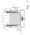
- FIGS. 1 and 2 the basic structure of a press screw separator according to the invention will be explained below.
- the reference numeral 1 shows a housing which defines an interior space in which a conveyor screw arrangement, which has the general reference numeral 3, is provided, which has an inner axial end 4 and an outer axial end 5.
- the housing 1 in the present embodiment of the invention is a steel welded construction, but it could also be a cast steel construction.
- the auger assembly 3 comprises an initial or inner peripheral portion A on which two or more augers 7 are mounted for common rotation with a worm shaft 8, and an outer portion B near the other axial end 5 which is free of augers.
- the worm shaft 8 has - as shown - a radial dimension which is fixed between the inner and outer axial end 4, 5.
- the area A occupies between 60 and 80% of the total length of the worm shaft 3, while its area B is between 20 and 40% of the worm shaft length.
- the assembly 9 comprises a drive shaft 10 which is suitably rotatably supported by a pair of axially spaced axial-radial roller bearing assemblies in a bearing housing 12 aligned with the central longitudinal axis of the worm shaft 8, for example, as indicated at 11, 11 '.
- the drive shaft 10 has opposite axial stub shafts 13, 13 ', one of which is in driving connection with the worm shaft 8, while the other stub shaft protrudes axially out of the worm shaft 8 and is in driving connection with a drive device 15 in the form of an electric motor.
- a belt or chain drive indicated at 16 is preferably provided, which connects an output shaft of the drive device 15 with the respective stub shaft 13.
- a reduction gear 17 is angdeutet to adjust the speed of the output shaft to a suitable level in predetermined levels or continuously.
- the invention is not limited to the one described Limited drive arrangement, but it could also be provided such as, for example, in the EP 0 367 037 B1 is described.
- a cylindrical screen basket 18 is arranged in the housing interior.
- the screen basket 18 preferably has a structure as described in more detail in the EP 0 367 037 B1 so that reference may be made thereto. This document is thus included in the disclosure of the present invention.
- the screen basket 18 is therefore preferably designed as a slotted screen, the screen bars are parallel to the axis, wherein the width of the gap between the screen bars is preferably between 0.2 mm and 1.5 mm.
- the screen basket 18 could be "floating" supported along its entire length relative to the housing 1, as shown in the EP 0 367 037 B1 is described.
- the strainer basket 18 is supported with a vertically aligned central longitudinal axis only on an end region facing the outer end 5 of the worm shaft 8 on the housing 1, ie at a point at which the greatest torques occur during operation.
- the screen basket 18 is axially penetrated by the screw conveyor assembly 3, wherein between the worm shaft 8 and the inner periphery of the screen basket 18, a circular cylindrical annulus S is formed, which has a uniform gap width s, which is in a certain ratio to the diameter of the worm shaft 8.
- the annulus S includes a first or inner portion 19 facing the inner axial end 4 of the worm shaft 8 and a second or outer axial portion 20 facing the outer axial end 5 of the worm shaft 8.
- the second axial portion 20 of the annular space S is free of screw flights 7, while the screw flights 7 are guided in the region of the first portion 19 with their outer edges to close to the inner peripheral surface of the screen basket 18.
- the ratio of the diameter of the worm shaft 8 to the gap width s of the annular space S is between 12 and 50, more preferably 25, and most preferably 12, and the gap width s of the annular space S is between 25 and 100 mm, preferably 50 and 75 mm preferably 75 mm.
- the ratio of the gap width s of the annular space S to the axial distance between adjacent screw flights can furthermore be ⁇ 1.0, preferably between 0.5 and 1.0, most preferably 0.75.
- Each screw 7 should be inclined at an angle between 70 ° and 80 ° relative to the central longitudinal axis of the screw shaft 8 in the conveying direction, wherein the distance between adjacent screw flights 7 should be between 80 and 120 mm.
- a tubular extension 21 is arranged on the housing 1 axially aligned with the annular space S.
- a further annular space 22 is defined, which is an axial continuation of the annular space S, but is not limited by the strainer 18 circumferentially.
- the worm shaft 8 is axially extended beyond the annular space 22 and carries at its protruding end one or more, in the present case four, equiangularly spaced blade-like elements 23 radially projecting from the outer circumference of the worm shaft 8 by a suitable amount and together rotate with the worm shaft 8.
- a solids outlet in the form of an obliquely outwardly from top to bottom facing chute 24 is provided, the inlet is aligned with the rotating blades 23, that the blades 23 are guided past the chute 24 in the rotation of the worm shaft 8 and so from the blades 23 entrained solid material to the chute 24 is transported.
- the plug undergoes a relaxation in the annular space 21 downstream annular expansion chamber 33 which is provided circumferentially of the screw shaft 8 near its protruding from the housing 1 end 5 at the exit from the annular space 21.
- the solid material decomposes due to the relaxation in a crumbly, free-flowing material, which is supplied through the blades 23 whose chute 24.
- an inlet port 25 for the slurry to be treated is provided on the housing 1 to supply it near the inner axial end of the screw conveyor assembly 3, so that the slurry can be caught by the coil.
- An outlet port 26 is further provided on the housing 1 at a location in alignment with the screen basket 18 to be able to discharge the deposited on the outer periphery of the screen basket 18 separated liquid to the outside.
- the plug is therefore increasingly dewatered in its movement to the annular space 22 of the tubular extension 21, so that finally at the outlet of Pressschnekkenseparators a plug remains which consists essentially of solid.
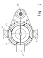
- the described stowage effect by plug formation can be enhanced by mounting a damper assembly 28 around the screw shaft 8 at the outlet end of the annular space 22 of the tubular extension 21 for common rotation therewith, as shown in FIG Fig. 4 and 5 is shown.
- the assembly 28 is preferably composed of a plurality of circumferentially at an equal angular distance from one another successively arranged circular segment-shaped base bodies 29 which cover the annular space 22 at least partially radially.
- a flap 30 is articulated. Each flap 30 can be moved against a biasing force exerted thereon by the solid plug from a position substantially aligned with the base body 29 to a position where the flap 30 more or less releases the annular space 22 behind it.
- the biasing force can be applied by a spring device or hydraulic device 31, preferably adjustable.
- the stowage flap arrangement 28 has the effect that the solids plug conveyed against it can not reach the chute 24 directly, but only when the pressure exerted by it has assumed such a degree that the flaps 30 are pivoted away. This results in increased compaction and thus drainage of the plug.
- Reference numeral 32 denotes blade-like members having a function similar to those of FIGS Fig. 3 have shown blades 23.
- the invention has been described above with reference to an embodiment in which the screw conveyor arrangement is vertically aligned. If desired, the central longitudinal axis of the auger assembly could also be inclined by a suitable amount of ⁇ 30 ° from the vertical. Also, one can horizontal alignment of the screw conveyor arrangement for certain to be treated sludge lead to a satisfactory deposition behavior.
- the damper assembly is not limited to the described embodiment.
- a stowage flap arrangement, as described for example in the Korean patent 0289887 could also be provided.
Claims (10)
- Séparateur à vis à pression pour la séparation de particules solides d'une eau trouble contenant des particules solides et liquides tels que des eaux usées communales, industrielles ou agricoles, du lisier, etc., présentant :- un boîtier (1),- un agencement de vis sans fin (3) disposé de manière à pouvoir tourner dans le boîtier, qui présente un arbre de vis (8) et au moins deux spires de vis (7) disposées dessus pour la rotation commune avec l'arbre de vis,- un entraînement pour la rotation de l'agencement de vis sans fin (3), un panier de tamisage (18) cylindrique maintenu dans le boîtier,- un espace annulaire (S) défini entre le côté intérieur du panier de tamisage et l'arbre de vis, qui présente une première section (19) axiale intérieure, dans laquelle parviennent les spires de vis, et une seconde section axiale extérieure (20) qui est exempte de spires de vis,- une entrée (25) disposée près d'une extrémité axiale intérieure de l'agencement de vis sans fin (3) pour l'eau trouble,- une sortie (26) communiquant avec le panier de tamisage pour les particules aqueuses de l'eau trouble, et- une sortie de solides disposée en aval de l'espace annulaire dans le sens de transport,- l'agencement de vis sans fin (3) comportant une première zone (A), sur laquelle sont disposées les spires de vis (8) et comportant une seconde zone (B) qui est exempte de spires de vis (8), et la première zone (A) s'étendant sur la première section axiale intérieure entière (19) et la seconde zone (B) sur la seconde section axiale extérieure entière (20) de sorte qu'un bouchon de solides puisse être réalisé dans la seconde section axiale extérieure (20),- caractérisé en ce que le rapport entre le diamètre de l'arbre de vis (8) et la largeur de fente (s) de l'espace annulaire (S) est compris entre 12 et 50 et la largeur de fente (s) de l'espace annulaire (S) est comprise entre 25 et 100 mm.
- Séparateur à vis à pression selon la revendication 1, caractérisé en ce que l'axe médian longitudinal de l'agencement de vis sans fin (3) est orienté selon un angle de 90° +/- 30° par rapport à l'horizontale.
- Séparateur à vis à pression selon la revendication 1 ou 2, caractérisé en ce que le rapport de largeur de fente (s) de l'espace annulaire (S) par rapport à la distance axiale entre des spires de vis contiguës (7) est ≤ 1, de préférence est compris entre 0,5 et 1, de manière préférée entre toutes s'élève à 0,75.
- Séparateur à vis à pression selon l'une quelconque des revendications précédentes, caractérisé en ce que chaque spire de vis (7) est inclinée selon un angle compris entre 70 et 80° par rapport à l'axe médian longitudinal de l'arbre de vis (8) dans le sens de transport.
- Séparateur à vis à pression selon l'une quelconque des revendications précédentes, caractérisé en ce que la distance entre des spires de vis contiguës (7) est comprise entre 80 et 120 mm.
- Séparateur à vis à pression selon l'une quelconque des revendications précédentes, caractérisé en ce qu'un prolongement (21) axial tubulaire présentant la sortie de solides est prévu sur l'extrémité axiale extérieure du boîtier (1), dans lequel l'arbre de vis (8) s'étend.
- Séparateur à vis à pression selon l'une quelconque des revendications précédentes, caractérisé en ce qu'au moins un élément d'entraînement (23) de type pale est monté sur une zone d'extrémité dépassant de la sortie de solides de l'arbre de vis (8) pour la rotation commune avec l'arbre de vis afin d'évacuer une masse de solides sortant de la sortie de solides dans la direction sensiblement tangentielle.
- Séparateur à vis à pression selon l'une quelconque des revendications précédentes, caractérisé en ce qu'une chambre de détente (33) entourant l'arbre de vis (8) pour le bouchon de solides sortant est prévue sur la sortie de solides.
- Séparateur à vis à pression selon l'une quelconque des revendications précédentes, caractérisé en ce que la sortie de solides peut être fermée par un agencement de clapets de retenue (28) pouvant pivoter sous une force axiale déterminée agissant dans le sens de rejet.
- Séparateur à vis à pression selon la revendication 9, caractérisé en ce que l'agencement de clapets de retenue (28) comporte une pluralité de clapets de retenue (30) précontraints recouvrant un espace annulaire de rejet (22) de la sortie de solides, répartis sur la périphérie de la zone d'extrémité en saillie de l'arbre de vis (8) pour la rotation commune avec l'arbre de vis.
Applications Claiming Priority (2)
| Application Number | Priority Date | Filing Date | Title |
|---|---|---|---|
| DE202007007606U DE202007007606U1 (de) | 2007-05-30 | 2007-05-30 | Pressschneckenseparator |
| PCT/DE2008/000423 WO2008145079A1 (fr) | 2007-05-30 | 2008-03-10 | Séparateur à vis à pression |
Publications (2)
| Publication Number | Publication Date |
|---|---|
| EP2155353A1 EP2155353A1 (fr) | 2010-02-24 |
| EP2155353B1 true EP2155353B1 (fr) | 2013-05-29 |
Family
ID=39581883
Family Applications (1)
| Application Number | Title | Priority Date | Filing Date |
|---|---|---|---|
| EP08734363.8A Not-in-force EP2155353B1 (fr) | 2007-05-30 | 2008-03-10 | Séparateur à vis à pression |
Country Status (5)
| Country | Link |
|---|---|
| US (1) | US20110048255A1 (fr) |
| EP (1) | EP2155353B1 (fr) |
| DE (2) | DE202007007606U1 (fr) |
| DK (1) | DK2155353T3 (fr) |
| WO (1) | WO2008145079A1 (fr) |
Cited By (1)
| Publication number | Priority date | Publication date | Assignee | Title |
|---|---|---|---|---|
| CN109293196A (zh) * | 2018-11-04 | 2019-02-01 | 临湘市东泰饲料机械有限公司 | 一种用于养猪场用来处理猪粪的固液分离机 |
Families Citing this family (10)
| Publication number | Priority date | Publication date | Assignee | Title |
|---|---|---|---|---|
| DE202008011369U1 (de) * | 2008-08-26 | 2008-11-27 | Fan Separator Gmbh | Pressschneckenseparator |
| AT509288B1 (de) * | 2009-12-29 | 2015-02-15 | Haider Reinhold | Anlage zum abtrennen von feststoffen aus wässrigen suspensionen, insbesondere kommunalen abwässern |
| IT1401039B1 (it) * | 2010-07-05 | 2013-07-12 | Wam Spa | Impianto di separazione a coclea per il trattamento di impasti liquidi |
| DE202011004153U1 (de) | 2011-03-18 | 2011-05-19 | Röhren- und Pumpenwerk Rudolf Bauer Ges.m.b.H., Steiermark | Pressschneckenseparator |
| EP2707206B1 (fr) | 2011-03-18 | 2019-05-15 | Röhren- und Pumpenwerk Bauer Gesellschaft mbH | Séparateur à vis de presse |
| GR1007661B (el) * | 2011-04-11 | 2012-07-30 | Σωτηρης Νικου Σωτηρελης | Μεθοδος διαχωρισμου και διαχειρισης διφασικου ελαιοπυρηνα κατα τη διαρκεια λειτουργιας ελαιοτριβειου ή μετα απο αποθηκευση και μεταφορα |
| DE102013112878A1 (de) * | 2013-11-21 | 2015-05-21 | Börger GmbH | Vorrichtung und Verfahren zum Eindicken von flüssigem feststoffhaltigem Substrat |
| AT515482B1 (de) * | 2014-03-14 | 2016-03-15 | Andritz Ag Maschf | Schneckenpresse |
| DE102017115080B4 (de) | 2017-07-06 | 2020-01-23 | Klingspohn Gmbh | Auslassstutzen und Vorrichtung zur Trennung der Bestandteile einer Feststoffe enthaltenden Flüssigkeit |
| DE202017105625U1 (de) | 2017-09-18 | 2017-09-29 | Klingspohn Gmbh | Vorrichtung zur Trennung der Bestandteile einer Feststoffe enthaltenden Flüssigkeit |
Family Cites Families (19)
| Publication number | Priority date | Publication date | Assignee | Title |
|---|---|---|---|---|
| BE332012A (fr) * | 1925-02-09 | |||
| US1835789A (en) * | 1928-01-30 | 1931-12-08 | American Voith Contact Co | Screw press |
| NL294351A (fr) * | 1962-06-22 | 1900-01-01 | ||
| US3188942A (en) | 1962-12-05 | 1965-06-15 | Somat Corp | Apparatus for disintegrating and dewatering fibrous material |
| DE2751703A1 (de) * | 1977-11-19 | 1979-05-23 | Krupp Gmbh | Verfahren und vorrichtung zum abpressen von fluessigkeiten |
| US4915830A (en) * | 1988-08-19 | 1990-04-10 | Sprout-Bauer, Inc. | Pulp wash press |
| DE58906496D1 (de) | 1988-11-03 | 1994-02-03 | Fan Engineering Gmbh | Verfahren zur Entwässerung von in Wasser suspendierten Feststoffen sowie Pressschneckenseparator dafür. |
| US5009795A (en) * | 1988-11-03 | 1991-04-23 | Fan Engineering Gmbh | Process for the dewatering of solids suspended in water and screw press separator therefor |
| DE4126382A1 (de) * | 1991-08-09 | 1993-02-11 | Fan Engineering Gmbh | Vorrichtung zum abtrennen von feststoffen aus fluessigkeiten |
| AT398090B (de) * | 1992-05-15 | 1994-09-26 | Andritz Patentverwaltung | Vorrichtung zum abtrennen von flüssigkeit aus feststoff-flüssigkeit-mischungen mit einer feststoffrückhalteeinrichtung sowie vorrichtung in form einer schneckenpresse |
| JP3352137B2 (ja) * | 1993-04-09 | 2002-12-03 | 株式会社泉精器製作所 | 生ゴミ脱水処理装置 |
| KR100289887B1 (ko) | 1994-03-09 | 2001-05-15 | 노먼 바이간드 | 고체를 포함하는 액체 매질로부터 고체를 분리하고 탈수하기 위한 스크류 프레스 분리기 |
| DE19521459A1 (de) * | 1995-06-13 | 1996-12-19 | Fan Engineering Gmbh | Verhältnis zwischen Tiefe und Abstand der Wendeln von Schnecken in Schneckenpressen |
| DE19521460A1 (de) * | 1995-06-13 | 1996-12-19 | Fan Engineering Gmbh | Führungs- und Schneidkeil in Schneckenpressen |
| JPH1133787A (ja) * | 1997-07-11 | 1999-02-09 | Kankaku Investment Kk | 生ゴミ粉砕処理装置 |
| GB2354720A (en) * | 1999-09-30 | 2001-04-04 | Imp Machine Company | Vertical screw press with cone weight having spring bias means and curved sides |
| JP2004276046A (ja) * | 2003-03-13 | 2004-10-07 | Furomu Kogyo:Kk | 生ゴミの圧縮処理装置 |
| US7347140B2 (en) * | 2005-01-21 | 2008-03-25 | Andritz Ag | Screw press for separation of liquid from solid-liquid mixtures especially pulp suspensions |
| DE102005002997A1 (de) * | 2005-01-23 | 2006-07-27 | Klass, Georg | Schneckenfilterpresse |
-
2007
- 2007-05-30 DE DE202007007606U patent/DE202007007606U1/de not_active Expired - Lifetime
-
2008
- 2008-03-10 EP EP08734363.8A patent/EP2155353B1/fr not_active Not-in-force
- 2008-03-10 WO PCT/DE2008/000423 patent/WO2008145079A1/fr active Application Filing
- 2008-03-10 DE DE112008002033T patent/DE112008002033A5/de not_active Withdrawn
- 2008-03-10 DK DK08734363.8T patent/DK2155353T3/da active
- 2008-03-10 US US12/602,350 patent/US20110048255A1/en not_active Abandoned
Cited By (1)
| Publication number | Priority date | Publication date | Assignee | Title |
|---|---|---|---|---|
| CN109293196A (zh) * | 2018-11-04 | 2019-02-01 | 临湘市东泰饲料机械有限公司 | 一种用于养猪场用来处理猪粪的固液分离机 |
Also Published As
| Publication number | Publication date |
|---|---|
| DE202007007606U1 (de) | 2008-10-09 |
| DE112008002033A5 (de) | 2010-04-29 |
| DK2155353T3 (da) | 2013-09-02 |
| WO2008145079A1 (fr) | 2008-12-04 |
| US20110048255A1 (en) | 2011-03-03 |
| EP2155353A1 (fr) | 2010-02-24 |
Similar Documents
| Publication | Publication Date | Title |
|---|---|---|
| EP2155353B1 (fr) | Séparateur à vis à pression | |
| DE102005014171B4 (de) | Extruder mit konischer Doppelschraube, Entwässerungsvorrichtung und deren Verwendung | |
| DE3301053A1 (de) | Vorrichtung zum abtrennen von fluessigkeit aus einem schlammartigen brei oder einem feststoffluessigkeitsgemenge | |
| DE69735774T2 (de) | Trennvorrichtung | |
| DE3709623C2 (fr) | ||
| EP0040425B1 (fr) | Dispositif pour évacuer des matériaux flottants et débris d'un égout, notamment d'une installation d'épuration | |
| DE3224204A1 (de) | Zentrifuge | |
| DE60318833T2 (de) | Dekantierzentrifuge | |
| WO2003078070A1 (fr) | Centrifugeuse a vis sans fin | |
| DE3046946A1 (de) | Dekantierzentrifuge | |
| DE3301099C2 (fr) | ||
| EP1305098B1 (fr) | Dispositif d'extraction permettant l'extraction de liquide a partir de corps solides, et son utilisation | |
| EP2707206B1 (fr) | Séparateur à vis de presse | |
| DE102009001054A1 (de) | Vollmantel-Schneckenzentrifuge mit Grobstoff-Auslass | |
| DE3029605A1 (de) | Kompaktfoerderer | |
| EP2438973A1 (fr) | Séparateur destiné à la séparation de matières solides, notamment à partir de liquides hautement visqueux | |
| EP0012461B1 (fr) | Installation de gazéification de charbon | |
| EP0448100B1 (fr) | Broyeur-mélangeur | |
| EP0747546B1 (fr) | Appareil et procédé pour enlever les déchets de l'eau | |
| DE10011949C2 (de) | Anlage zur Verarbeitung von umweltbelastenden Abprodukten | |
| DE202008011369U1 (de) | Pressschneckenseparator | |
| EP4015424A1 (fr) | Bunker pourvu de dispositif de déchargement | |
| EP1949966B1 (fr) | Centrifugeuse à vis sans fin à bol plein dotée d'une chicane de mesure | |
| CH659008A5 (de) | Traegheitsseparator. | |
| DE1298463C2 (de) | Entwaesserungschoepfrad fuer Sand-Kies-Gewinnungsanlagen |
Legal Events
| Date | Code | Title | Description |
|---|---|---|---|
| PUAI | Public reference made under article 153(3) epc to a published international application that has entered the european phase |
Free format text: ORIGINAL CODE: 0009012 |
|
| 17P | Request for examination filed |
Effective date: 20091013 |
|
| AK | Designated contracting states |
Kind code of ref document: A1 Designated state(s): AT BE BG CH CY CZ DE DK EE ES FI FR GB GR HR HU IE IS IT LI LT LU LV MC MT NL NO PL PT RO SE SI SK TR |
|
| AX | Request for extension of the european patent |
Extension state: AL BA MK RS |
|
| 17Q | First examination report despatched |
Effective date: 20100409 |
|
| DAX | Request for extension of the european patent (deleted) | ||
| GRAP | Despatch of communication of intention to grant a patent |
Free format text: ORIGINAL CODE: EPIDOSNIGR1 |
|
| GRAS | Grant fee paid |
Free format text: ORIGINAL CODE: EPIDOSNIGR3 |
|
| GRAA | (expected) grant |
Free format text: ORIGINAL CODE: 0009210 |
|
| AK | Designated contracting states |
Kind code of ref document: B1 Designated state(s): AT BE BG CH CY CZ DE DK EE ES FI FR GB GR HR HU IE IS IT LI LT LU LV MC MT NL NO PL PT RO SE SI SK TR |
|
| REG | Reference to a national code |
Ref country code: GB Ref legal event code: FG4D Free format text: NOT ENGLISH |
|
| REG | Reference to a national code |
Ref country code: CH Ref legal event code: EP |
|
| REG | Reference to a national code |
Ref country code: AT Ref legal event code: REF Ref document number: 613994 Country of ref document: AT Kind code of ref document: T Effective date: 20130615 |
|
| REG | Reference to a national code |
Ref country code: IE Ref legal event code: FG4D Free format text: LANGUAGE OF EP DOCUMENT: GERMAN |
|
| REG | Reference to a national code |
Ref country code: DE Ref legal event code: R096 Ref document number: 502008010023 Country of ref document: DE Effective date: 20130725 |
|
| REG | Reference to a national code |
Ref country code: CH Ref legal event code: NV Representative=s name: KELLER AND PARTNER PATENTANWAELTE AG, CH |
|
| REG | Reference to a national code |
Ref country code: DK Ref legal event code: T3 |
|
| REG | Reference to a national code |
Ref country code: NL Ref legal event code: T3 |
|
| REG | Reference to a national code |
Ref country code: LT Ref legal event code: MG4D |
|
| PG25 | Lapsed in a contracting state [announced via postgrant information from national office to epo] |
Ref country code: NO Free format text: LAPSE BECAUSE OF FAILURE TO SUBMIT A TRANSLATION OF THE DESCRIPTION OR TO PAY THE FEE WITHIN THE PRESCRIBED TIME-LIMIT Effective date: 20130829 Ref country code: ES Free format text: LAPSE BECAUSE OF FAILURE TO SUBMIT A TRANSLATION OF THE DESCRIPTION OR TO PAY THE FEE WITHIN THE PRESCRIBED TIME-LIMIT Effective date: 20130909 Ref country code: SI Free format text: LAPSE BECAUSE OF FAILURE TO SUBMIT A TRANSLATION OF THE DESCRIPTION OR TO PAY THE FEE WITHIN THE PRESCRIBED TIME-LIMIT Effective date: 20130529 Ref country code: LT Free format text: LAPSE BECAUSE OF FAILURE TO SUBMIT A TRANSLATION OF THE DESCRIPTION OR TO PAY THE FEE WITHIN THE PRESCRIBED TIME-LIMIT Effective date: 20130529 Ref country code: GR Free format text: LAPSE BECAUSE OF FAILURE TO SUBMIT A TRANSLATION OF THE DESCRIPTION OR TO PAY THE FEE WITHIN THE PRESCRIBED TIME-LIMIT Effective date: 20130830 Ref country code: PT Free format text: LAPSE BECAUSE OF FAILURE TO SUBMIT A TRANSLATION OF THE DESCRIPTION OR TO PAY THE FEE WITHIN THE PRESCRIBED TIME-LIMIT Effective date: 20130930 Ref country code: IS Free format text: LAPSE BECAUSE OF FAILURE TO SUBMIT A TRANSLATION OF THE DESCRIPTION OR TO PAY THE FEE WITHIN THE PRESCRIBED TIME-LIMIT Effective date: 20130929 Ref country code: FI Free format text: LAPSE BECAUSE OF FAILURE TO SUBMIT A TRANSLATION OF THE DESCRIPTION OR TO PAY THE FEE WITHIN THE PRESCRIBED TIME-LIMIT Effective date: 20130529 Ref country code: SE Free format text: LAPSE BECAUSE OF FAILURE TO SUBMIT A TRANSLATION OF THE DESCRIPTION OR TO PAY THE FEE WITHIN THE PRESCRIBED TIME-LIMIT Effective date: 20130529 |
|
| PG25 | Lapsed in a contracting state [announced via postgrant information from national office to epo] |
Ref country code: HR Free format text: LAPSE BECAUSE OF FAILURE TO SUBMIT A TRANSLATION OF THE DESCRIPTION OR TO PAY THE FEE WITHIN THE PRESCRIBED TIME-LIMIT Effective date: 20130529 Ref country code: PL Free format text: LAPSE BECAUSE OF FAILURE TO SUBMIT A TRANSLATION OF THE DESCRIPTION OR TO PAY THE FEE WITHIN THE PRESCRIBED TIME-LIMIT Effective date: 20130529 Ref country code: BG Free format text: LAPSE BECAUSE OF FAILURE TO SUBMIT A TRANSLATION OF THE DESCRIPTION OR TO PAY THE FEE WITHIN THE PRESCRIBED TIME-LIMIT Effective date: 20130829 |
|
| PG25 | Lapsed in a contracting state [announced via postgrant information from national office to epo] |
Ref country code: LV Free format text: LAPSE BECAUSE OF FAILURE TO SUBMIT A TRANSLATION OF THE DESCRIPTION OR TO PAY THE FEE WITHIN THE PRESCRIBED TIME-LIMIT Effective date: 20130529 |
|
| PG25 | Lapsed in a contracting state [announced via postgrant information from national office to epo] |
Ref country code: SK Free format text: LAPSE BECAUSE OF FAILURE TO SUBMIT A TRANSLATION OF THE DESCRIPTION OR TO PAY THE FEE WITHIN THE PRESCRIBED TIME-LIMIT Effective date: 20130529 Ref country code: EE Free format text: LAPSE BECAUSE OF FAILURE TO SUBMIT A TRANSLATION OF THE DESCRIPTION OR TO PAY THE FEE WITHIN THE PRESCRIBED TIME-LIMIT Effective date: 20130529 Ref country code: CZ Free format text: LAPSE BECAUSE OF FAILURE TO SUBMIT A TRANSLATION OF THE DESCRIPTION OR TO PAY THE FEE WITHIN THE PRESCRIBED TIME-LIMIT Effective date: 20130529 |
|
| PG25 | Lapsed in a contracting state [announced via postgrant information from national office to epo] |
Ref country code: RO Free format text: LAPSE BECAUSE OF FAILURE TO SUBMIT A TRANSLATION OF THE DESCRIPTION OR TO PAY THE FEE WITHIN THE PRESCRIBED TIME-LIMIT Effective date: 20130529 Ref country code: IT Free format text: LAPSE BECAUSE OF FAILURE TO SUBMIT A TRANSLATION OF THE DESCRIPTION OR TO PAY THE FEE WITHIN THE PRESCRIBED TIME-LIMIT Effective date: 20130529 |
|
| PLBE | No opposition filed within time limit |
Free format text: ORIGINAL CODE: 0009261 |
|
| STAA | Information on the status of an ep patent application or granted ep patent |
Free format text: STATUS: NO OPPOSITION FILED WITHIN TIME LIMIT |
|
| 26N | No opposition filed |
Effective date: 20140303 |
|
| REG | Reference to a national code |
Ref country code: DE Ref legal event code: R097 Ref document number: 502008010023 Country of ref document: DE Effective date: 20140303 |
|
| GBPC | Gb: european patent ceased through non-payment of renewal fee |
Effective date: 20140310 |
|
| REG | Reference to a national code |
Ref country code: IE Ref legal event code: MM4A |
|
| PG25 | Lapsed in a contracting state [announced via postgrant information from national office to epo] |
Ref country code: IE Free format text: LAPSE BECAUSE OF NON-PAYMENT OF DUE FEES Effective date: 20140310 Ref country code: GB Free format text: LAPSE BECAUSE OF NON-PAYMENT OF DUE FEES Effective date: 20140310 |
|
| REG | Reference to a national code |
Ref country code: FR Ref legal event code: PLFP Year of fee payment: 8 |
|
| REG | Reference to a national code |
Ref country code: CH Ref legal event code: PCAR Free format text: NEW ADDRESS: EIGERSTRASSE 2 POSTFACH, 3000 BERN 14 (CH) |
|
| PGFP | Annual fee paid to national office [announced via postgrant information from national office to epo] |
Ref country code: DK Payment date: 20150325 Year of fee payment: 8 Ref country code: CH Payment date: 20150325 Year of fee payment: 8 Ref country code: LU Payment date: 20150323 Year of fee payment: 8 Ref country code: NL Payment date: 20150323 Year of fee payment: 8 |
|
| PGFP | Annual fee paid to national office [announced via postgrant information from national office to epo] |
Ref country code: FR Payment date: 20150319 Year of fee payment: 8 Ref country code: AT Payment date: 20150320 Year of fee payment: 8 |
|
| PGFP | Annual fee paid to national office [announced via postgrant information from national office to epo] |
Ref country code: DE Payment date: 20150331 Year of fee payment: 8 |
|
| PG25 | Lapsed in a contracting state [announced via postgrant information from national office to epo] |
Ref country code: MT Free format text: LAPSE BECAUSE OF FAILURE TO SUBMIT A TRANSLATION OF THE DESCRIPTION OR TO PAY THE FEE WITHIN THE PRESCRIBED TIME-LIMIT Effective date: 20130529 |
|
| PG25 | Lapsed in a contracting state [announced via postgrant information from national office to epo] |
Ref country code: MC Free format text: LAPSE BECAUSE OF FAILURE TO SUBMIT A TRANSLATION OF THE DESCRIPTION OR TO PAY THE FEE WITHIN THE PRESCRIBED TIME-LIMIT Effective date: 20130529 |
|
| PG25 | Lapsed in a contracting state [announced via postgrant information from national office to epo] |
Ref country code: CY Free format text: LAPSE BECAUSE OF FAILURE TO SUBMIT A TRANSLATION OF THE DESCRIPTION OR TO PAY THE FEE WITHIN THE PRESCRIBED TIME-LIMIT Effective date: 20130529 |
|
| PG25 | Lapsed in a contracting state [announced via postgrant information from national office to epo] |
Ref country code: TR Free format text: LAPSE BECAUSE OF FAILURE TO SUBMIT A TRANSLATION OF THE DESCRIPTION OR TO PAY THE FEE WITHIN THE PRESCRIBED TIME-LIMIT Effective date: 20130529 Ref country code: HU Free format text: LAPSE BECAUSE OF FAILURE TO SUBMIT A TRANSLATION OF THE DESCRIPTION OR TO PAY THE FEE WITHIN THE PRESCRIBED TIME-LIMIT; INVALID AB INITIO Effective date: 20080310 |
|
| REG | Reference to a national code |
Ref country code: DE Ref legal event code: R119 Ref document number: 502008010023 Country of ref document: DE |
|
| REG | Reference to a national code |
Ref country code: DK Ref legal event code: EBP Effective date: 20160331 |
|
| PG25 | Lapsed in a contracting state [announced via postgrant information from national office to epo] |
Ref country code: LU Free format text: LAPSE BECAUSE OF NON-PAYMENT OF DUE FEES Effective date: 20160310 |
|
| REG | Reference to a national code |
Ref country code: CH Ref legal event code: PL |
|
| REG | Reference to a national code |
Ref country code: AT Ref legal event code: MM01 Ref document number: 613994 Country of ref document: AT Kind code of ref document: T Effective date: 20160310 |
|
| REG | Reference to a national code |
Ref country code: NL Ref legal event code: MM Effective date: 20160401 |
|
| REG | Reference to a national code |
Ref country code: FR Ref legal event code: ST Effective date: 20161130 |
|
| PG25 | Lapsed in a contracting state [announced via postgrant information from national office to epo] |
Ref country code: LI Free format text: LAPSE BECAUSE OF NON-PAYMENT OF DUE FEES Effective date: 20160331 Ref country code: FR Free format text: LAPSE BECAUSE OF NON-PAYMENT OF DUE FEES Effective date: 20160331 Ref country code: CH Free format text: LAPSE BECAUSE OF NON-PAYMENT OF DUE FEES Effective date: 20160331 Ref country code: NL Free format text: LAPSE BECAUSE OF NON-PAYMENT OF DUE FEES Effective date: 20160401 Ref country code: DE Free format text: LAPSE BECAUSE OF NON-PAYMENT OF DUE FEES Effective date: 20161001 |
|
| PG25 | Lapsed in a contracting state [announced via postgrant information from national office to epo] |
Ref country code: AT Free format text: LAPSE BECAUSE OF NON-PAYMENT OF DUE FEES Effective date: 20160310 |
|
| PG25 | Lapsed in a contracting state [announced via postgrant information from national office to epo] |
Ref country code: DK Free format text: LAPSE BECAUSE OF NON-PAYMENT OF DUE FEES Effective date: 20160331 |
|
| PG25 | Lapsed in a contracting state [announced via postgrant information from national office to epo] |
Ref country code: BE Free format text: LAPSE BECAUSE OF NON-PAYMENT OF DUE FEES Effective date: 20140331 |