EP2164635B1 - Apparatus for mincing a product for mincing - Google Patents
Apparatus for mincing a product for mincing Download PDFInfo
- Publication number
- EP2164635B1 EP2164635B1 EP08758727.5A EP08758727A EP2164635B1 EP 2164635 B1 EP2164635 B1 EP 2164635B1 EP 08758727 A EP08758727 A EP 08758727A EP 2164635 B1 EP2164635 B1 EP 2164635B1
- Authority
- EP
- European Patent Office
- Prior art keywords
- perforated plate
- rotary shaft
- sealing ring
- seal
- ejector
- Prior art date
- Legal status (The legal status is an assumption and is not a legal conclusion. Google has not performed a legal analysis and makes no representation as to the accuracy of the status listed.)
- Active
Links
Images
Classifications
-
- B—PERFORMING OPERATIONS; TRANSPORTING
- B02—CRUSHING, PULVERISING, OR DISINTEGRATING; PREPARATORY TREATMENT OF GRAIN FOR MILLING
- B02C—CRUSHING, PULVERISING, OR DISINTEGRATING IN GENERAL; MILLING GRAIN
- B02C18/00—Disintegrating by knives or other cutting or tearing members which chop material into fragments
- B02C18/30—Mincing machines with perforated discs and feeding worms
- B02C18/301—Mincing machines with perforated discs and feeding worms with horizontal axis
- B02C18/304—Mincing machines with perforated discs and feeding worms with horizontal axis with several axially aligned knife-perforated disc units
-
- B—PERFORMING OPERATIONS; TRANSPORTING
- B02—CRUSHING, PULVERISING, OR DISINTEGRATING; PREPARATORY TREATMENT OF GRAIN FOR MILLING
- B02C—CRUSHING, PULVERISING, OR DISINTEGRATING IN GENERAL; MILLING GRAIN
- B02C18/00—Disintegrating by knives or other cutting or tearing members which chop material into fragments
- B02C18/30—Mincing machines with perforated discs and feeding worms
- B02C18/305—Details
-
- B—PERFORMING OPERATIONS; TRANSPORTING
- B02—CRUSHING, PULVERISING, OR DISINTEGRATING; PREPARATORY TREATMENT OF GRAIN FOR MILLING
- B02C—CRUSHING, PULVERISING, OR DISINTEGRATING IN GENERAL; MILLING GRAIN
- B02C18/00—Disintegrating by knives or other cutting or tearing members which chop material into fragments
- B02C18/30—Mincing machines with perforated discs and feeding worms
Definitions
- the invention relates to a device for crushing a comminuted material, in particular for meat processing, by means of at least one arranged in a housing perforated plate and this associated with a rotary shaft cutting blade, the rotary shaft passes through the perforated plate and in this area between the perforated plate and rotating shaft by maintaining a distance Gap is formed.
- Such devices are known in many forms and configurations and in use. So describe the DE 39 15 409 C2 and also the DE 199 60 409 A1
- a device in which a plurality of cutting sets are provided, each of a perforated plate and a cutting head consist.
- the Schneldkopf in turn is provided with cutting blades. Cutting material is crushed during the impressions in holes of the respective perforated plates by the cutting blades, the perforated plates stand still, while the cutting heads rotate with a drive shaft. Since the perforated plates are provided in the machining direction of the material to be cut with ever-decreasing bore diameters, the material to be cut is further and further crushed until finally it reaches an ejector. This leads to the shredded material to an ejection opening not shown in detail.
- a corresponding device is in the DE 10 49 729 disclosed.
- the annular gap between the perforated plate and the recess in the drive shaft with a seal which is lubricated by the crushing material itself, closed.
- the seal is elastic.
- the object of the present invention is to eliminate the abovementioned disadvantages and to provide a device of the above-mentioned type. To create a way in which the quality of the product obtained is significantly improved.
- the gap between the perforated plate and the rotary shaft is closed by a seal, wherein the seal is arranged radially movable.
- This seal may have different configurations.
- it is thought to form the seal as a sealing ring, which is fixed in an inner diameter of the perforated plate and engages in a groove of the Drehwelle- or, an ejector. Between a bottom of the groove and the sealing ring, however, there is sufficient clearance, so that the sealing ring can move radially at a vibration of the rotary shaft. The gap can remain on this catfish, without coarse particles can get into the already comminuted meat.
- the seal is also designed as a sealing ring. Only the arrangement of the sealing ring has changed.
- the sealing ring is now firmly connected to the rotary shaft or the ejector and engages in a groove of the perforated plate. Again, the sealing ring in the groove has enough clearance, so that the sealing ring can move radially in the oscillation of the rotary shaft.
- a corner bead od.
- Be in which the sealing ring engages
- a retaining ring should be provided to prevent the sealing ring slips out of the corner bead.
- the seal can speak in Recesses or grooves float, which are arranged in the inner diameter of the perforated plate andlor the outer diameter of the rotary shaft and the ejector.
- Recesses or grooves float which are arranged in the inner diameter of the perforated plate andlor the outer diameter of the rotary shaft and the ejector.
- an axial seal is also ensured, the necessary gap can remain and still sufficient clearance is present, so that the seal can move radially in the vibration of the rotary shaft. This possibility should also be encompassed by the present invention.
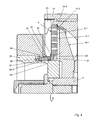
- Another embodiment of the seal provides a mechanical seal, which is arranged between the perforated plate and the ejector. Further refinements and arrangements of the seal are conceivable and are intended to be encompassed by the present invention. For example, it is thought to provide such a seal not only in the last perforated plate in conjunction with the ejector, but already in the previous perforated plates in conjunction with the rotary shaft. For here too it is to be prevented that coarse particles which do not correspond to the degree of comminution of the respective following perforated plate are nevertheless pressed through.
- the sealing ring must be able to radially adapt to the vibration of the rotary shaft, without that a material abrasion of the perforated plate or a wear of the seal is given.
- the individual seals are preferably made of plastic, ceramic or metal.
- plastic in particular glass fiber reinforced Teflon is preferred.
- Teflon As a metal, bronze is conceivable, since this is approved in the food industry. Further materials are conceivable and are intended to be encompassed by the present invention.
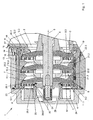
- FIG. 1 is of a device for crushing a crushed material, approximately corresponding to DE 39 15 409 C2 , Essentially only one crushing area 1 shown.
- This comminuting area 1 has an inlet opening 2 for the comminuted material and an ejection area 3, which in the present exemplary embodiment is covered by a hood 4.
- the comminuted material is conveyed from the inlet opening 2 to the ejection area 3 parallel to a longitudinal axis 5 of a rotary shaft 6, wherein the rotary shaft 6 protrudes through the inlet opening 2 into an approximately cylindrical housing 7, which is connected on the one hand with an inlet funnel 8 and on the other hand from the hood 4 is covered.
- Each quick set A, B and C consists of a perforated plate 9.1, 9.2 and 9.3 and a cutting head 10.1, 10.2 and 10.3, which Schneldklingen 11.1, 11.2 and 11.3.
- the cutting blades 11.1, 11.2 and 11.3 strip on the perforated plates 9.1, 9.2 and 9.3 along or are guided at a distance approximately equal to zero along the perforated plates 9.1, 9.2 and 9.3.
- Holes 12.3 in the perforated plate 9.3 are larger than holes 12.2 in the perforated plate 9.2. These are in turn larger than holes 12.1 in the perforated plate 9.1.
- the cutting heads 10.1 to 10.3 are non-rotatably mounted on the rotary shaft 6 and rotate with the rotary shaft 6 about the longitudinal axis 5.
- the perforated plates 9.1 to 9.3, however, are stationary in a sleeve-shaped actuating body 13 is arranged. This in turn is seated in the housing 7, wherein an externally threaded portion 14 engages the adjusting body 13 in an internally threaded portion 15 on the housing 7.
- this adjusting body 13 can thereby be moved in the direction of the longitudinal axis 5, wherein the perforated plates 9.1 to 9.3 taken and thereby the distance between each perforated plate 9.1 to 9.3 to the corresponding cutting blade 11.1 to 11.3 is changed.
- the rotation of the actuator 13 is preferably done via a worm gear not shown in detail or a stepper motor, on the output shaft, a corresponding pinion is seated, which is in engagement with a toothing 16 of a spur gear 17.
- This spur gear 17 is connected by appropriate screws 18 with the actuating body 13.
- the spacer ring 21.3 again forms an annular stop 20.2 for the perforated plate 9.2, which is also pressed by spring-loaded pressure pin 22.2 against this ring stop 20.2.
- the pressure pin 22.2 is located in a further spacer ring 21.2, which in turn forms a ring stop 20.1 for the perforated plate 9.1.
- an ejector 25 is provided, which is preferably rotatably connected to the rotary shaft 6.
- Crushed, in particular meat is introduced through the inlet opening 2 and enters the area of the cutting set C.
- the perforated plate 9.3 stands still while the cutting head 10.3 rotates with the rotary shaft 6, so that the material to be cut during the impressions in the holes 12.3 through the cutting blades 11.3 is crushed. In the holes 12.3 with the largest diameter, a rough pre-crushing takes place.
- the sausage meat reaches the cutting set B with the perforated plate 9.2 with the bores 12.2 of medium diameter. Again, the sausage meat is pressed into these holes 12.2 and simultaneously crushed by the cutting blades 11.2 moving along the perforated plate 9.2.
- the material to be crushed reaches the cutting set A, in which the perforated plate 9.1 is arranged with the holes 12.1 with the smallest diameter. Again, the sausage meat is pressed into these holes 12.1 and further crushed when pushed in by the cutting blades 11.1.
- the comminuted material enters the ejection region 3, in which it is fed by the ejector 25 of an ejection opening not shown in detail.
- the drive not shown in detail is set in action, so that it rotates about the teeth 16, the spur gear 17 and the spur gear 17 and the adjusting body 13.
- the internal thread 15 meshes in the external thread 14, so that the adjusting body 13 is moved along the longitudinal axis 5.
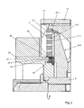
- a sealing ring 29.1 is provided in order to seal this gap 28, so that no uncut coarse fractions are pressed through it into the already comminuted material.
- This sealing ring 29.1 is defined in the inner diameter 26 of the perforated plate 9.1 and engages in a groove 30 of the ejector 25 and ensures an axial in both directions seal to the ejector 25 out.
- the sealing ring 29.1 has sufficient clearance in the groove 30, so that the sealing ring 29.1 can move radially in the groove 30 upon oscillation of the rotary shaft 6. The gap 28 can remain on this catfish without coarse particles can get into the already comminuted meat.
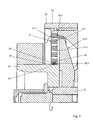
- FIG. 3 another embodiment of a gasket is shown.
- the sealing ring 29.2 sits firmly on the outer diameter 27 of the ejector 25 and engages in a groove 32 of the perforated plate 9.1.
- the sealing ring 29.2 again has sufficient clearance, so that the sealing ring 29.2 move radially in the groove 32 during the oscillation of the rotary shaft 6.
Landscapes
- Engineering & Computer Science (AREA)
- Food Science & Technology (AREA)
- Crushing And Pulverization Processes (AREA)
Description
Die Erfindung betrifft eine Vorrichtung zum Zerkleinern eines Zerkleinerungsgutes, insbesondere für die Fleischverarbeitung, mittels zumindest einer in einem Gehäuse angeordneten Lochplatte und dieser an einer Drehwelle zugeordneten Schneidklinge, wobei die Drehwelle die Lochplatte durchsetzt und in diesem Bereich zwischen Lochplatte und Drehwelle durch Einhaltung eines Abstands ein Spalt ausgebildet ist.The invention relates to a device for crushing a comminuted material, in particular for meat processing, by means of at least one arranged in a housing perforated plate and this associated with a rotary shaft cutting blade, the rotary shaft passes through the perforated plate and in this area between the perforated plate and rotating shaft by maintaining a distance Gap is formed.
Derartige Vorrichtungen sind in vielfältiger Form und Ausgestaltung bekannt und gebräuchlich. So beschreiben die
Nachteilig hierbei Ist Jedoch, dass aufgrund der Schwingung der Antriebswelle mit den Schneldköpfen insbesondere zwischen einem Innendurchmesser der Lochplatte/n und einem Aussendurchmesser der Drehwelle oder des Auswerfers ein Spalt vorgesehen sein muss. Dieser muss ausreichend gross sein, damit gewährleistet werden kann, dass ein Materialabrieb an dem Innendurchmesser der Lochplatte und damit auch eine Verunreinigung des Schneidgutes möglichst gering gehalten wird, welcher durch die Schwingung der Antriebswelle mit den Schneidköpfen zwangläufig gegeben ist. Allerdings wird somit durch diesen Spalt noch unzerkleinertes Schneidgut gedrückt, so dass sich In dem vollständig zerkleinerten Schneidgut auch Grobpartikel befinden. Dies ist höchst unerwünscht.The disadvantage here is, however, that due to the vibration of the drive shaft with the Schneldköpfen in particular between an inner diameter of the perforated plate / n and an outer diameter of the rotary shaft or the ejector, a gap must be provided. This must be sufficiently large, so that it can be ensured that a material abrasion on the inner diameter of the perforated plate and thus contamination of the material to be cut is minimized, which is inevitably given by the vibration of the drive shaft with the cutting heads. However, uncut material to be cut is thus pressed through this gap, so that coarse particles are also present in the completely comminuted material to be cut. This is highly undesirable.
Versuche, diesen Spalt zu verringern, indem auf eine Stahlnabe des Auswerfers ein Kunststoffring gepresst wurde, führten zu dem Nachteil, dass der Kunststoffring durch die Schwingung der Antriebswelle mit den Schneidköpfen einem hohen Verschlelss unterlag, was unter anderem aus Kostengründen ebenfalls unerwünscht ist.Attempts to reduce this gap by pressing on a steel hub of the ejector a plastic ring, to the disadvantage that the plastic ring was subject by the oscillation of the drive shaft with the cutting heads a high Verschlelss, which is also undesirable for cost reasons.
Eine entsprechende Vorrichtung wird in der
Aufgabe der vorliegenden Erfindung ist es, die oben genannten Nachteile zu beseitigen und eine Vorrichtung der o.g. Art zu schaffen, bei welcher die Qualität des erhalten Produktes wesentlich verbessert wird.The object of the present invention is to eliminate the abovementioned disadvantages and to provide a device of the above-mentioned type. To create a way in which the quality of the product obtained is significantly improved.
Zur Lösung dieser Aufgabe führen die Merkmale des kennzeichnenden Teils des Anspruchs 1.To achieve this object, the features of the characterizing part of claim 1.
Inbesondere ist der Spalt zwischen Lochplatte und Drehwelle durch eine Dichtung verschlossen, wobei die Dichtung radial beweglich angeordnet ist.In particular, the gap between the perforated plate and the rotary shaft is closed by a seal, wherein the seal is arranged radially movable.
Diese Dichtung kann unterschiedliche Ausgestaltungen aufweisen. So ist bei einem Ausführungsbeispiel daran gedacht, die Dichtung als Dichtring auszubilden, welcher In einem Innendurchmesser der Lochplatte festgelegt ist und in eine Nut der Drehwelle- bzw, eines Auswerferes eingreift. Zwischen einem Boden der Nut und dem Dichtring besteht jedoch ausreichend Spiel, so dass sich der Dichtring bei einer Schwingung der Drehwelle radial bewegen kann. Der Spalt kann auf diese Welse bestehen bleiben, ohne dass Grobanteile in das bereits zerkleinerte Brät geraten können.This seal may have different configurations. Thus, in one embodiment, it is thought to form the seal as a sealing ring, which is fixed in an inner diameter of the perforated plate and engages in a groove of the Drehwelle- or, an ejector. Between a bottom of the groove and the sealing ring, however, there is sufficient clearance, so that the sealing ring can move radially at a vibration of the rotary shaft. The gap can remain on this catfish, without coarse particles can get into the already comminuted meat.
Bei einem weiteren Ausführungsbeispiel der Dichtung ist die Dichtung ebenfalls als Dichtring ausgestaltet. Lediglich die Anordnung des Dichtringes hat sich verändert. Hier ist der Dichtring nun fest mit der Drehwelle bzw. dem Auswerfer verbunden und greift In eine Nut der Lochplatte ein. Erneut hat der Dichtring in der Nut ausreichend Spiel , so dass sich der Dichtring bei der Schwingung der Drehwelle radial bewegen kann.In a further embodiment of the seal, the seal is also designed as a sealing ring. Only the arrangement of the sealing ring has changed. Here, the sealing ring is now firmly connected to the rotary shaft or the ejector and engages in a groove of the perforated plate. Again, the sealing ring in the groove has enough clearance, so that the sealing ring can move radially in the oscillation of the rotary shaft.
Anstelle einer Nut in der Lochplatte oder der Drehwelle bzw, dem Auswerfer kann selbstverständlich auch eine Ecksicke od. dgl. vorgesehen werden, In welche der Dichtring eingreift, Im Falle einer Ecksicke sollte allerdings beispielsweise ein Haltering vorgesehen sein, um zu verhindern, dass der Dichtring aus der Ecksicke rutscht. Weitere Ausgestaltungen sind denkbar und sollen von der vorliegenden Erfindung umfasst sein.Instead of a groove in the perforated plate or the rotary shaft or the ejector, of course, a corner bead od. Like. Be provided, in which the sealing ring engages, In the case of a corner bead, however, for example, a retaining ring should be provided to prevent the sealing ring slips out of the corner bead. Further embodiments are conceivable and should be encompassed by the present invention.
Weiterhin ist denkbar, die Dichtung weder in dem Innendurchmesser der Lochplatte noch auf dem Aussendurchmesser der Drehwelle bzw. des Auswerferes festzulegen, Stattdessen kann die Dichtung sozusagen in Ausnehmungen bzw. Nuten schwimmen, welche in dem Innendurchmesser der Lochplatte undloder dem Aussendurchmesser der Drehwelle bzw. des Auswerferes angeordnet sind. Hierbei wird ebenfalls eine axiale Abdichtung gewährleistet, der notwendige Spalt kann bestehen bleiben und trotzdem ist ausreichend Spiel vorhanden, so dass sich die Dichtung bei der Schwingung der Drehwelle radial bewegen kann. Auch diese Möglichkeit soll von der vorliegenden Erfindung umfasst sein.Furthermore, it is conceivable to set the seal neither in the inner diameter of the perforated plate nor on the outer diameter of the rotary shaft or the ejector, instead, the seal can speak in Recesses or grooves float, which are arranged in the inner diameter of the perforated plate andlor the outer diameter of the rotary shaft and the ejector. Here, an axial seal is also ensured, the necessary gap can remain and still sufficient clearance is present, so that the seal can move radially in the vibration of the rotary shaft. This possibility should also be encompassed by the present invention.
Ein weiteres Ausführungsbeispiel der Dichtung sieht eine Gleitringdichtung vor, welche zwischen der Lochplatte und dem Auswerfer angeordnet ist.
Weiter Ausgestaltungen und Anordnungen der Dichtung sind denkbar und sollen von der vorliegenden Erfindung umfasst sein. So ist beispielsweise daran gedacht, eine derartige Dichtung nicht nur bei der letzten Lochplatte in Verbindung mit dem Auswerfer vorzusehen, sondern bereits bei den vorherigen Lochplatten in Verbindung mit der Drehwelle. Denn auch hier soll verhindert werden, dass Grobpartikel, welche dem Zerkleinerungsgrad der jeweils folgenden Lochplatte nicht entsprechen, dennoch durchgepresst werden.Another embodiment of the seal provides a mechanical seal, which is arranged between the perforated plate and the ejector.
Further refinements and arrangements of the seal are conceivable and are intended to be encompassed by the present invention. For example, it is thought to provide such a seal not only in the last perforated plate in conjunction with the ejector, but already in the previous perforated plates in conjunction with the rotary shaft. For here too it is to be prevented that coarse particles which do not correspond to the degree of comminution of the respective following perforated plate are nevertheless pressed through.
Wichtig bei den unterschiedlichen Möglichkeiten der Ausgestaltung und Anordnung der Dichtung ist, dass eine axiale Abdichtung des Spaltes in beide Richtungen gewährleistet wird, so dass zum einen verhindert wird, dass Grobantelle in das bereits zerkleinerte Brät geraten. Zum anderen muss sich der Dichtring bei der Schwingung der Drehwelle radial anpassen können, ohne dass ein Materialabrieb der Lochplatte oder ein Verschleiss der Dichtung gegeben ist.Important in the different possibilities of the design and arrangement of the seal is that an axial seal of the gap is ensured in both directions, so that on the one hand prevents Grobantelle get into the already comminuted meat. On the other hand, the sealing ring must be able to radially adapt to the vibration of the rotary shaft, without that a material abrasion of the perforated plate or a wear of the seal is given.
Die einzelnen Dichtungen bestehen bevorzugt aus Kunststoff, Keramik oder Metall. Im Falle der Herstellung aus Kunststoff wird insbesondere glasfaserverstärktes Teflon bevorzugt. Als Metall ist Bronze denkbar, da dieses in der Lebensmittelindustrie zugelassen ist. Weiter Materialien sind denkbar und sollen von der vorliegenden Erfindung umfasst sein.The individual seals are preferably made of plastic, ceramic or metal. In the case of production from plastic, in particular glass fiber reinforced Teflon is preferred. As a metal, bronze is conceivable, since this is approved in the food industry. Further materials are conceivable and are intended to be encompassed by the present invention.
Weitere Vorteile, Merkmale und Einzelheiten der Erfindung ergeben sich aus der nachfolgenden Beschreibung bevorzugter Ausführungsbeispiele sowie anhand der Zeichnung; diese zeigt in
-
Figur 1 einen teilweise dargestellten Längsschnitt durch einen Zerkleinerungsbereich einer erfindungsgemässen Vorrichtung zum Zerkleinern eines Zerkleinerungsgutes; -
Figur 2Figur 1 mit einem Ausführungsbeispiel einer erfindungagemässen Dichtung; -
Figur 3Figur 1 mit einem weiteren Ausführungsbeispiel einer erfindungsgemässen Dichtung.
-
FIG. 1 a partially illustrated longitudinal section through a crushing region of an inventive device for crushing a crushed material; -
FIG. 2 an enlarged section of the device according toFIG. 1 with an embodiment of a erfindungagemässen seal; -
FIG. 3 enlarged shown sections of the device according toFIG. 1 with a further embodiment of a seal according to the invention.
Gemäss
Das Zerkleinerungsgut wird von der Eintrittsöffnung 2 zum Auswurfbereich 3 parallel zu einer Längsachse 5 einer Drehwelle 6 gefördert, wobei die Drehwelle 6 durch die Eintrittsöffnung 2 In ein etwa zylindrisches Gehäuse 7 einragt, welches einerseits mit einem Einlauftrichter 8 In Verbindung steht und andererseits von der Haube 4 abgedeckt ist.The comminuted material is conveyed from the inlet opening 2 to the
In dem Gehäuse 7 sind drei Schneidsätze A, B und C vorgesehen. Jeder Schneldsatz A, B und C besteht aus einer Lochplatte 9.1, 9.2 und 9.3 sowie einem Schneidkopf 10.1, 10.2 und 10.3, welcher Schneldklingen 11.1, 11.2 und 11.3 aufweist. Die Schneidklingen 11.1, 11.2 und 11.3 streifen an den Lochplatten 9.1, 9.2 und 9.3 entlang bzw. sind in einem Abstand etwa gleich Null entlang den Lochplatten 9.1, 9.2 bzw. 9.3 geführt. Bohrungen 12.3 in der Lochplatte 9.3 sind grösser als Bohrungen 12.2 in der Lochplatte 9.2. Diese sind wiederum grösser als Bohrungen 12.1 in der Lochplatte 9.1.In the
Die Schneidköpfe 10.1 bis 10.3 sitzen drehfest auf der Drehwelle 6 und drehen mit der Drehwelle 6 um die Längsachse 5. Die Lochplatten 9.1 bis 9.3 sind dagegen ortsfest in einem hülsenförmigen Stellkörper 13 angeordnet. Dieser sitzt wiederum in dem Gehäuse 7, wobei ein Aussengewindeabschnitt 14 an dem Stellkörper 13 in ein Innengewindeabschnitt 15 an dem Gehäuse 7 eingreift. Beim Drehen des Stellkörpers 13 kann dadurch dieser Stellkörper 13 in Richtung der Längsachse 5 bewegt werden, wobei die Lochplatten 9.1 bis 9.3 mitgenommen und hierdurch der Abstand jeder Lochplatte 9.1 bis 9.3 zu der entsprechenden Schneidklinge 11.1 bis 11.3 verändert wird.The cutting heads 10.1 to 10.3 are non-rotatably mounted on the
Das Drehen des Stellkörpers 13 geschieht bevorzugt über ein nicht näher gezeigtes Schneckengetriebe oder auch einen Schrittmotor, auf dessen Abtriebswelle ein entsprechendes Ritzel sitzt, welches mit einer Verzahnung 16 eines Stirnrades 17 in Eingriff steht. Dieses Stirnrad 17 ist durch entsprechende Schrauben 18 mit dem Stellkörper 13 verbunden.The rotation of the
Im vorliegenden Ausführungsbeispiel ragt vom Stirnrad 17 ein Innenflansch 19 in den Stellkörper 13 und bildet einen Ringanschlag 20.3 für die Lochplatte 9.3 aus. Andererseits trifft auf die Lochplatte 9.3 ein Distanzring 21.3 mit federgelagerten Druckbolzen 22.3. Diese Druckbolzen 22.3 drücken die Lochplatte 9.3 gegen den Ringanschlag 20.3, um eine sich ändernde Lochplattendicke zu korrigieren.In the present embodiment protrudes from the
Der Distanzring 21.3 bildet wiederum einen Ringanschlag 20.2 für die Lochplatte 9.2 aus, die ebenfalls durch federgelagerte Druckbolzen 22.2 gegen diesen Ringanschlag 20.2 gedrückt wird.The spacer ring 21.3 again forms an annular stop 20.2 for the perforated plate 9.2, which is also pressed by spring-loaded pressure pin 22.2 against this ring stop 20.2.
Der Druckbolzen 22.2 befindet sich in einem weiteren Distanzring 21.2, der wiederum einen Ringanschlag 20.1 für die Lochplatte 9.1 ausbildet.The pressure pin 22.2 is located in a further spacer ring 21.2, which in turn forms a ring stop 20.1 for the perforated plate 9.1.
Den Abschluss der Schneidsätze A, B und C bildet dann ein in den Stellkörper 13 eingeschraubter Spannring 23.The conclusion of the cutting sets A, B and C then forms a screwed into the
Von der Haube 4 überdeckt, ist ein Auswerfer 25 vorgesehen, welcher mit der Drehwelle 6 vorzugsweise drehfest verbunden ist.Covered by the
Die Funktionsweise der vorliegenden Erfindung ist folgende:The operation of the present invention is as follows:
Zerkleinerungsgut, insbesondere Brät, wird durch die Eintrittsöffnung 2 eingeführt und gelangt in den Bereich des Schneidsatzes C. Die Lochplatte 9.3 steht still, während der Schneidkopf 10.3 mit der Drehwelle 6 dreht, so dass das Schneidgut während dem Eindrücken in die Bohrungen 12.3 durch die Schneidklingen 11.3 zerkleinert wird. In den Bohrungen 12.3 mit dem grössten Durchmesser findet eine grobe Vorzerkleinerung statt.Crushed, in particular meat, is introduced through the
Von dem Schneidsatz C gelangt das Brät zu dem Schneidsatz B mit der Lochplatte 9.2 mit den Bohrungen 12.2 mittleren Durchmessers. Auch hier wird das Brät in diese Bohrungen 12.2 hineingedrückt und gleichzeitig durch die an der Lochplatte 9.2 entlangfahrenden Schneidklingen 11.2 zerkleinert.From the cutting set C, the sausage meat reaches the cutting set B with the perforated plate 9.2 with the bores 12.2 of medium diameter. Again, the sausage meat is pressed into these holes 12.2 and simultaneously crushed by the cutting blades 11.2 moving along the perforated plate 9.2.
Nunmehr gelangt das zu zerkleinernde Gut zum Schneidsatz A, in dem die Lochplatte 9.1 mit den Bohrungen 12.1 mit dem geringsten Durchmesser angeordnet ist. Auch hier wird das Brät in diese Bohrungen 12.1 hineingedrückt und beim Hineindrücken durch die Schneidklingen 11.1 weiter zerkleinert.Now the material to be crushed reaches the cutting set A, in which the perforated plate 9.1 is arranged with the holes 12.1 with the smallest diameter. Again, the sausage meat is pressed into these holes 12.1 and further crushed when pushed in by the cutting blades 11.1.
Schliesslich gelangt das zerkleinerte Gut in den Auswurfbereich 3, in dem es von dem Auswerfer 25 einer nicht näher gezeigten Auswurföffnung zugeführt wird.Finally, the comminuted material enters the
Wird festgestellt, dass die Tätigkeit zwischen Schneidklingen und Lochplatten nicht mehr optimal ist, muss der Abstand zwischen Schneidklingen und Lochplatten verstellt werden. Hierzu wird der nicht näher gezeigte Antrieb in Tätigkeit gesetzt, so dass er über die Verzahnung 16 das Stirnrad 17 und mit dem Stirnrad 17 auch den Stellkörper 13 dreht. Dabei kämmt das Innengewinde 15 in dem Aussengewinde 14, so dass der Stellkörper 13 entlang der Längsachse 5 bewegt wird.If it is determined that the activity between cutting blades and perforated plates is no longer optimal, the distance between cutting blades and perforated plates must be adjusted. For this purpose, the drive not shown in detail is set in action, so that it rotates about the
Aufgrund der starken Schwingung der Drehwelle 6 mit den Schneidköpfen 10.1, 10.2 und 10.3 während der Zerkleinerungstätigkeiten muss zwischen einem Innendurchmesser 26 beispielsweise der Lochplatte 9.1 und einem Aussendurchmesser 27 des Auswerfers 25 ein Spalt 28 vorgesehen sein. Dies ist In
Um diesen Spalt 28 abzudichten, so dass durch ihn keine unzerkleinerten Grobanteile in das bereits zerkleinerte Gut gepresst werden, ist ein Dichtring 29.1 vorgesehen. Dieser Dichtring 29.1 Ist In dem Innendurchmesser 26 der Lochplatte 9.1 festgelegt und greift in eine Nut 30 des Auswerferes 25 ein und gewährleistet eine in beide Richtungen axiale Abdichtung zu dem Auswerfer 25 hin. Gleichzeitig hat der Dichtring 29.1 ausreichend Spiel In der Nut 30, so dass sich der Dichtring 29.1 bei Schwingung der Drehwelle 6 radial in der Nut 30 bewegen kann. Der Spalt 28 kann auf diese Welse bestehen bleiben, ohne dass Grobanteile in das bereits zerkleinerte Brät geraten können.In order to seal this
Gemäss der
Claims (8)
- A device for cutting up a product to be cut up, in particular for processing meat, by means of at least one perforated plate (9.1, 9.2, 9.3) arranged in a housing (7) and cutting blade (11.1, 11.2, 11.3) associated with said plate on a rotary shaft (6), the rotary shaft (6) penetrating the perforated plate (9.1, 9.2, 9.3) and a gap (28) being formed in this region between the perforated plate (9.1, 9.2, 9.3) and the rotary shaft (6) by observing a distance,
characterised in that
the gap (28) between the perforated plate (9.1, 9.2, 9.3) and the rotary shaft (6) is closed by a seal (29.1, 29.2, 29.3), the seal being a sealing ring (29.1, 29.2, 29.3) and the sealing ring (29.1, 29.2, 29.3) being arranged to be radially movable. - A device according to Claim 1, characterised in that an ejector (25) is provided between the perforated plate (9.1, 9.2, 9.3) and the rotary shaft (6), which ejector is connected to the rotary shaft (6) in rotation-resistant manner and which forms the gap (28) towards the perforated plate (9.1, 9.2, 9.3), which gap again is closed by the sealing ring (29.1, 29.2, 29.3).
- A device according to at least one of Claims 1 to 2, characterised in that the sealing ring (29.1, 29.2, 29.3) consists of plastics material, ceramic or metal.
- A device according to at least one of Claims 1 to 3, characterised in that the sealing ring (29.1, 29.2) is arranged in a groove (30, 32) or a corner bead of the rotary shaft (6) or the ejector (25).
- A device according to Claim 4, characterised in that the sealing ring (29.1, 29.2) is held in the corner bead by a holding ring.
- A device according to Claim 4, characterised in that the sealing ring (29.1) is fixed in an internal diameter (26) of the perforated plate (9.1, 9.2, 9.3) and engages in the groove (30) or the corner bead.
- A device according to at least one of Claims 1 to 3, characterised in that the sealing ring (29.2) engages in a groove (32) or corner bead of the perforated plate (9.1, 9.2, 9.3).
- A device according to Claim 7, characterised in that the sealing ring (29.2) is connected securely to the rotary shaft (6) or the ejector (25).
Applications Claiming Priority (2)
| Application Number | Priority Date | Filing Date | Title |
|---|---|---|---|
| DE200710025899 DE102007025899B4 (en) | 2007-06-01 | 2007-06-01 | Device for crushing a comminuted material |
| PCT/EP2008/004133 WO2008145310A1 (en) | 2007-06-01 | 2008-05-23 | Apparatus for mincing a product for mincing |
Publications (2)
| Publication Number | Publication Date |
|---|---|
| EP2164635A1 EP2164635A1 (en) | 2010-03-24 |
| EP2164635B1 true EP2164635B1 (en) | 2013-08-21 |
Family
ID=39760558
Family Applications (1)
| Application Number | Title | Priority Date | Filing Date |
|---|---|---|---|
| EP08758727.5A Active EP2164635B1 (en) | 2007-06-01 | 2008-05-23 | Apparatus for mincing a product for mincing |
Country Status (3)
| Country | Link |
|---|---|
| EP (1) | EP2164635B1 (en) |
| DE (1) | DE102007025899B4 (en) |
| WO (1) | WO2008145310A1 (en) |
Cited By (1)
| Publication number | Priority date | Publication date | Assignee | Title |
|---|---|---|---|---|
| EP3984711A4 (en) * | 2019-11-21 | 2022-08-24 | LG Chem, Ltd. | COMPOSITE CHOPPER FOR SUPERABSORBENT HYDROGEL |
Families Citing this family (2)
| Publication number | Priority date | Publication date | Assignee | Title |
|---|---|---|---|---|
| DE102014216720A1 (en) | 2014-08-22 | 2016-02-25 | Karl Schnell Gmbh & Co. Kg | Crushing machine for crushing a product |
| DE102022111847A1 (en) * | 2022-05-11 | 2023-11-16 | Inotec Gmbh Maschinenentwicklung U. Vertrieb | Device for shredding a material to be shredded |
Family Cites Families (7)
| Publication number | Priority date | Publication date | Assignee | Title |
|---|---|---|---|---|
| DE1049729B (en) | 1959-01-29 | |||
| DE641396C (en) * | 1934-01-03 | 1937-01-29 | Financ Mercuria S O F I M E Ho | Perforated disc for meat mincers |
| US2694426A (en) * | 1951-10-23 | 1954-11-16 | Cincinnati Butchers Supply Co | Plate and spider assembly for material grinding machines |
| AT320464B (en) * | 1968-03-01 | 1975-02-10 | Vemag Verdener Masch App | Meat mincing machine with at least one perforated disc, in front of which a multi-armed cutter head rotates |
| JPS62286560A (en) * | 1986-06-04 | 1987-12-12 | 株式会社 平賀工作所 | Chopper |
| DE3915409C2 (en) * | 1989-05-11 | 1998-09-17 | Inotec Gmbh Maschinenentwicklu | Shredding machine, in particular for the meat processing industry |
| DE19960409A1 (en) * | 1999-12-15 | 2001-06-21 | Inotec Gmbh Maschinenentwicklu | Device for comminuting a material to be comminuted |
-
2007
- 2007-06-01 DE DE200710025899 patent/DE102007025899B4/en not_active Expired - Fee Related
-
2008
- 2008-05-23 WO PCT/EP2008/004133 patent/WO2008145310A1/en not_active Ceased
- 2008-05-23 EP EP08758727.5A patent/EP2164635B1/en active Active
Cited By (1)
| Publication number | Priority date | Publication date | Assignee | Title |
|---|---|---|---|---|
| EP3984711A4 (en) * | 2019-11-21 | 2022-08-24 | LG Chem, Ltd. | COMPOSITE CHOPPER FOR SUPERABSORBENT HYDROGEL |
Also Published As
| Publication number | Publication date |
|---|---|
| DE102007025899B4 (en) | 2011-03-03 |
| EP2164635A1 (en) | 2010-03-24 |
| DE102007025899A1 (en) | 2008-12-04 |
| WO2008145310A1 (en) | 2008-12-04 |
Similar Documents
| Publication | Publication Date | Title |
|---|---|---|
| DE1101745B (en) | Milling and kneading device on screw presses for thermoplastic masses | |
| EP2987557B1 (en) | Grinding machine for grinding of a product | |
| EP2189221A2 (en) | Stirring ball mill | |
| DE4223043C2 (en) | Extruder with throttle punch | |
| EP3831494B1 (en) | Cutting mill for cutting down samples | |
| EP1237656B1 (en) | Device for comminuting a good to be comminuted | |
| EP2164635B1 (en) | Apparatus for mincing a product for mincing | |
| DE102019106758A1 (en) | Cutting device; Separator; Method for separating food components by means of a separator | |
| EP2036710B1 (en) | Rotor for a rotary tablet compactor | |
| DE4037816A1 (en) | ROLLING MILL | |
| DE10026825C2 (en) | comminution device | |
| EP0574694B1 (en) | Cutting tool for a machine for comminution of pasty substances | |
| DE102012008545A1 (en) | Device for preparing and production of biomass materials with entry and exit opening, has screen mechanism tools that are arranged such that to partially overlap on screening elements | |
| DE2154353A1 (en) | CUTTING MACHINE FOR MEAT OR THE LIKE. (WOLF) | |
| EP1132139B1 (en) | Meat grinder | |
| DE10312605B4 (en) | Device for separating and removing raw materials | |
| DE102004050810A1 (en) | Single-shaft, continuous mixing and kneading machine | |
| DE202014105678U1 (en) | Perforated disk, cutting system with it as well as crushing machine | |
| DE19624574C1 (en) | Location of feed and work worms for meat mincer | |
| DE19534674C2 (en) | Ring knife for meat grinders | |
| DE19942311C2 (en) | Clamping and pull-out system | |
| DE10237220C1 (en) | Cassette blade set, for mincing machine, has pre-cutter and two cutters of differing size preceding respective aperture discs | |
| DE102022111847A1 (en) | Device for shredding a material to be shredded | |
| DE2002735C3 (en) | Grinding apparatus | |
| DE700473C (en) | Grinding and crushing device |
Legal Events
| Date | Code | Title | Description |
|---|---|---|---|
| PUAI | Public reference made under article 153(3) epc to a published international application that has entered the european phase |
Free format text: ORIGINAL CODE: 0009012 |
|
| 17P | Request for examination filed |
Effective date: 20091229 |
|
| AK | Designated contracting states |
Kind code of ref document: A1 Designated state(s): AT BE BG CH CY CZ DE DK EE ES FI FR GB GR HR HU IE IS IT LI LT LU LV MC MT NL NO PL PT RO SE SI SK TR |
|
| AX | Request for extension of the european patent |
Extension state: AL BA MK RS |
|
| DAX | Request for extension of the european patent (deleted) | ||
| 17Q | First examination report despatched |
Effective date: 20110609 |
|
| GRAP | Despatch of communication of intention to grant a patent |
Free format text: ORIGINAL CODE: EPIDOSNIGR1 |
|
| INTG | Intention to grant announced |
Effective date: 20130422 |
|
| GRAS | Grant fee paid |
Free format text: ORIGINAL CODE: EPIDOSNIGR3 |
|
| GRAA | (expected) grant |
Free format text: ORIGINAL CODE: 0009210 |
|
| AK | Designated contracting states |
Kind code of ref document: B1 Designated state(s): AT BE BG CH CY CZ DE DK EE ES FI FR GB GR HR HU IE IS IT LI LT LU LV MC MT NL NO PL PT RO SE SI SK TR |
|
| REG | Reference to a national code |
Ref country code: GB Ref legal event code: FG4D Free format text: NOT ENGLISH |
|
| REG | Reference to a national code |
Ref country code: CH Ref legal event code: EP |
|
| REG | Reference to a national code |
Ref country code: AT Ref legal event code: REF Ref document number: 627741 Country of ref document: AT Kind code of ref document: T Effective date: 20130915 |
|
| REG | Reference to a national code |
Ref country code: IE Ref legal event code: FG4D Free format text: LANGUAGE OF EP DOCUMENT: GERMAN |
|
| REG | Reference to a national code |
Ref country code: DE Ref legal event code: R096 Ref document number: 502008010529 Country of ref document: DE Effective date: 20131017 |
|
| REG | Reference to a national code |
Ref country code: NL Ref legal event code: VDEP Effective date: 20130821 |
|
| REG | Reference to a national code |
Ref country code: LT Ref legal event code: MG4D |
|
| PG25 | Lapsed in a contracting state [announced via postgrant information from national office to epo] |
Ref country code: NO Free format text: LAPSE BECAUSE OF FAILURE TO SUBMIT A TRANSLATION OF THE DESCRIPTION OR TO PAY THE FEE WITHIN THE PRESCRIBED TIME-LIMIT Effective date: 20131121 Ref country code: CY Free format text: LAPSE BECAUSE OF FAILURE TO SUBMIT A TRANSLATION OF THE DESCRIPTION OR TO PAY THE FEE WITHIN THE PRESCRIBED TIME-LIMIT Effective date: 20130821 Ref country code: HR Free format text: LAPSE BECAUSE OF FAILURE TO SUBMIT A TRANSLATION OF THE DESCRIPTION OR TO PAY THE FEE WITHIN THE PRESCRIBED TIME-LIMIT Effective date: 20130821 Ref country code: SE Free format text: LAPSE BECAUSE OF FAILURE TO SUBMIT A TRANSLATION OF THE DESCRIPTION OR TO PAY THE FEE WITHIN THE PRESCRIBED TIME-LIMIT Effective date: 20130821 Ref country code: PT Free format text: LAPSE BECAUSE OF FAILURE TO SUBMIT A TRANSLATION OF THE DESCRIPTION OR TO PAY THE FEE WITHIN THE PRESCRIBED TIME-LIMIT Effective date: 20131223 Ref country code: LT Free format text: LAPSE BECAUSE OF FAILURE TO SUBMIT A TRANSLATION OF THE DESCRIPTION OR TO PAY THE FEE WITHIN THE PRESCRIBED TIME-LIMIT Effective date: 20130821 Ref country code: IS Free format text: LAPSE BECAUSE OF FAILURE TO SUBMIT A TRANSLATION OF THE DESCRIPTION OR TO PAY THE FEE WITHIN THE PRESCRIBED TIME-LIMIT Effective date: 20131221 |
|
| PG25 | Lapsed in a contracting state [announced via postgrant information from national office to epo] |
Ref country code: GR Free format text: LAPSE BECAUSE OF FAILURE TO SUBMIT A TRANSLATION OF THE DESCRIPTION OR TO PAY THE FEE WITHIN THE PRESCRIBED TIME-LIMIT Effective date: 20131122 Ref country code: LV Free format text: LAPSE BECAUSE OF FAILURE TO SUBMIT A TRANSLATION OF THE DESCRIPTION OR TO PAY THE FEE WITHIN THE PRESCRIBED TIME-LIMIT Effective date: 20130821 Ref country code: FI Free format text: LAPSE BECAUSE OF FAILURE TO SUBMIT A TRANSLATION OF THE DESCRIPTION OR TO PAY THE FEE WITHIN THE PRESCRIBED TIME-LIMIT Effective date: 20130821 Ref country code: PL Free format text: LAPSE BECAUSE OF FAILURE TO SUBMIT A TRANSLATION OF THE DESCRIPTION OR TO PAY THE FEE WITHIN THE PRESCRIBED TIME-LIMIT Effective date: 20130821 Ref country code: SI Free format text: LAPSE BECAUSE OF FAILURE TO SUBMIT A TRANSLATION OF THE DESCRIPTION OR TO PAY THE FEE WITHIN THE PRESCRIBED TIME-LIMIT Effective date: 20130821 |
|
| PG25 | Lapsed in a contracting state [announced via postgrant information from national office to epo] |
Ref country code: NL Free format text: LAPSE BECAUSE OF FAILURE TO SUBMIT A TRANSLATION OF THE DESCRIPTION OR TO PAY THE FEE WITHIN THE PRESCRIBED TIME-LIMIT Effective date: 20130821 Ref country code: RO Free format text: LAPSE BECAUSE OF FAILURE TO SUBMIT A TRANSLATION OF THE DESCRIPTION OR TO PAY THE FEE WITHIN THE PRESCRIBED TIME-LIMIT Effective date: 20130821 Ref country code: DK Free format text: LAPSE BECAUSE OF FAILURE TO SUBMIT A TRANSLATION OF THE DESCRIPTION OR TO PAY THE FEE WITHIN THE PRESCRIBED TIME-LIMIT Effective date: 20130821 Ref country code: EE Free format text: LAPSE BECAUSE OF FAILURE TO SUBMIT A TRANSLATION OF THE DESCRIPTION OR TO PAY THE FEE WITHIN THE PRESCRIBED TIME-LIMIT Effective date: 20130821 Ref country code: SK Free format text: LAPSE BECAUSE OF FAILURE TO SUBMIT A TRANSLATION OF THE DESCRIPTION OR TO PAY THE FEE WITHIN THE PRESCRIBED TIME-LIMIT Effective date: 20130821 Ref country code: CZ Free format text: LAPSE BECAUSE OF FAILURE TO SUBMIT A TRANSLATION OF THE DESCRIPTION OR TO PAY THE FEE WITHIN THE PRESCRIBED TIME-LIMIT Effective date: 20130821 |
|
| PG25 | Lapsed in a contracting state [announced via postgrant information from national office to epo] |
Ref country code: ES Free format text: LAPSE BECAUSE OF FAILURE TO SUBMIT A TRANSLATION OF THE DESCRIPTION OR TO PAY THE FEE WITHIN THE PRESCRIBED TIME-LIMIT Effective date: 20130821 Ref country code: IT Free format text: LAPSE BECAUSE OF FAILURE TO SUBMIT A TRANSLATION OF THE DESCRIPTION OR TO PAY THE FEE WITHIN THE PRESCRIBED TIME-LIMIT Effective date: 20130821 |
|
| PLBE | No opposition filed within time limit |
Free format text: ORIGINAL CODE: 0009261 |
|
| STAA | Information on the status of an ep patent application or granted ep patent |
Free format text: STATUS: NO OPPOSITION FILED WITHIN TIME LIMIT |
|
| 26N | No opposition filed |
Effective date: 20140522 |
|
| REG | Reference to a national code |
Ref country code: DE Ref legal event code: R097 Ref document number: 502008010529 Country of ref document: DE Effective date: 20140522 |
|
| PG25 | Lapsed in a contracting state [announced via postgrant information from national office to epo] |
Ref country code: LU Free format text: LAPSE BECAUSE OF FAILURE TO SUBMIT A TRANSLATION OF THE DESCRIPTION OR TO PAY THE FEE WITHIN THE PRESCRIBED TIME-LIMIT Effective date: 20140523 |
|
| REG | Reference to a national code |
Ref country code: CH Ref legal event code: PL |
|
| GBPC | Gb: european patent ceased through non-payment of renewal fee |
Effective date: 20140523 |
|
| PG25 | Lapsed in a contracting state [announced via postgrant information from national office to epo] |
Ref country code: CH Free format text: LAPSE BECAUSE OF NON-PAYMENT OF DUE FEES Effective date: 20140531 Ref country code: MC Free format text: LAPSE BECAUSE OF FAILURE TO SUBMIT A TRANSLATION OF THE DESCRIPTION OR TO PAY THE FEE WITHIN THE PRESCRIBED TIME-LIMIT Effective date: 20130821 Ref country code: LI Free format text: LAPSE BECAUSE OF NON-PAYMENT OF DUE FEES Effective date: 20140531 |
|
| REG | Reference to a national code |
Ref country code: IE Ref legal event code: MM4A |
|
| REG | Reference to a national code |
Ref country code: FR Ref legal event code: ST Effective date: 20150130 |
|
| PG25 | Lapsed in a contracting state [announced via postgrant information from national office to epo] |
Ref country code: IE Free format text: LAPSE BECAUSE OF NON-PAYMENT OF DUE FEES Effective date: 20140523 |
|
| PG25 | Lapsed in a contracting state [announced via postgrant information from national office to epo] |
Ref country code: FR Free format text: LAPSE BECAUSE OF NON-PAYMENT OF DUE FEES Effective date: 20140602 Ref country code: GB Free format text: LAPSE BECAUSE OF NON-PAYMENT OF DUE FEES Effective date: 20140523 |
|
| REG | Reference to a national code |
Ref country code: DE Ref legal event code: R082 Ref document number: 502008010529 Country of ref document: DE Representative=s name: PATENTANWAELTE UND RECHTSANWALT DR. WEISS, ARA, DE Ref country code: DE Ref legal event code: R082 Ref document number: 502008010529 Country of ref document: DE Representative=s name: PATENTANWAELTE UND RECHTSANWALT WEISS, ARAT & , DE |
|
| PG25 | Lapsed in a contracting state [announced via postgrant information from national office to epo] |
Ref country code: MT Free format text: LAPSE BECAUSE OF FAILURE TO SUBMIT A TRANSLATION OF THE DESCRIPTION OR TO PAY THE FEE WITHIN THE PRESCRIBED TIME-LIMIT Effective date: 20130821 |
|
| PG25 | Lapsed in a contracting state [announced via postgrant information from national office to epo] |
Ref country code: BG Free format text: LAPSE BECAUSE OF FAILURE TO SUBMIT A TRANSLATION OF THE DESCRIPTION OR TO PAY THE FEE WITHIN THE PRESCRIBED TIME-LIMIT Effective date: 20130821 |
|
| PG25 | Lapsed in a contracting state [announced via postgrant information from national office to epo] |
Ref country code: BE Free format text: LAPSE BECAUSE OF FAILURE TO SUBMIT A TRANSLATION OF THE DESCRIPTION OR TO PAY THE FEE WITHIN THE PRESCRIBED TIME-LIMIT Effective date: 20140531 Ref country code: HU Free format text: LAPSE BECAUSE OF FAILURE TO SUBMIT A TRANSLATION OF THE DESCRIPTION OR TO PAY THE FEE WITHIN THE PRESCRIBED TIME-LIMIT; INVALID AB INITIO Effective date: 20080523 Ref country code: TR Free format text: LAPSE BECAUSE OF FAILURE TO SUBMIT A TRANSLATION OF THE DESCRIPTION OR TO PAY THE FEE WITHIN THE PRESCRIBED TIME-LIMIT Effective date: 20130821 |
|
| PGFP | Annual fee paid to national office [announced via postgrant information from national office to epo] |
Ref country code: AT Payment date: 20250519 Year of fee payment: 18 |
|
| PGFP | Annual fee paid to national office [announced via postgrant information from national office to epo] |
Ref country code: DE Payment date: 20250728 Year of fee payment: 18 |