EP2163789B1 - Étagère et son procédé de formation - Google Patents
Étagère et son procédé de formation Download PDFInfo
- Publication number
- EP2163789B1 EP2163789B1 EP09252188A EP09252188A EP2163789B1 EP 2163789 B1 EP2163789 B1 EP 2163789B1 EP 09252188 A EP09252188 A EP 09252188A EP 09252188 A EP09252188 A EP 09252188A EP 2163789 B1 EP2163789 B1 EP 2163789B1
- Authority
- EP
- European Patent Office
- Prior art keywords
- rack
- strips
- brazing
- rail
- stairlift
- Prior art date
- Legal status (The legal status is an assumption and is not a legal conclusion. Google has not performed a legal analysis and makes no representation as to the accuracy of the status listed.)
- Active
Links
- 238000000034 method Methods 0.000 title claims abstract description 21
- 238000005219 brazing Methods 0.000 claims description 26
- RYGMFSIKBFXOCR-UHFFFAOYSA-N Copper Chemical compound [Cu] RYGMFSIKBFXOCR-UHFFFAOYSA-N 0.000 claims description 13
- 229910052802 copper Inorganic materials 0.000 claims description 13
- 239000010949 copper Substances 0.000 claims description 13
- 239000000463 material Substances 0.000 claims description 7
- 238000003466 welding Methods 0.000 claims description 7
- 239000002131 composite material Substances 0.000 claims description 5
- 230000006698 induction Effects 0.000 claims description 5
- 238000005452 bending Methods 0.000 claims description 4
- 238000005304 joining Methods 0.000 claims description 2
- 238000004519 manufacturing process Methods 0.000 description 10
- 238000010924 continuous production Methods 0.000 description 6
- 229910052751 metal Inorganic materials 0.000 description 5
- 239000002184 metal Substances 0.000 description 5
- 238000009434 installation Methods 0.000 description 4
- 239000004411 aluminium Substances 0.000 description 2
- 229910052782 aluminium Inorganic materials 0.000 description 2
- XAGFODPZIPBFFR-UHFFFAOYSA-N aluminium Chemical compound [Al] XAGFODPZIPBFFR-UHFFFAOYSA-N 0.000 description 2
- 238000011065 in-situ storage Methods 0.000 description 2
- 238000003754 machining Methods 0.000 description 2
- 238000003825 pressing Methods 0.000 description 2
- 230000007704 transition Effects 0.000 description 2
- 229910001209 Low-carbon steel Inorganic materials 0.000 description 1
- 229910000831 Steel Inorganic materials 0.000 description 1
- 230000001174 ascending effect Effects 0.000 description 1
- 230000009286 beneficial effect Effects 0.000 description 1
- 238000005520 cutting process Methods 0.000 description 1
- 230000003090 exacerbative effect Effects 0.000 description 1
- 238000001125 extrusion Methods 0.000 description 1
- 238000010438 heat treatment Methods 0.000 description 1
- 238000003801 milling Methods 0.000 description 1
- 239000000203 mixture Substances 0.000 description 1
- 230000007935 neutral effect Effects 0.000 description 1
- 229910001220 stainless steel Inorganic materials 0.000 description 1
- 239000010935 stainless steel Substances 0.000 description 1
- 239000010959 steel Substances 0.000 description 1
Images


Classifications
-
- B—PERFORMING OPERATIONS; TRANSPORTING
- B23—MACHINE TOOLS; METAL-WORKING NOT OTHERWISE PROVIDED FOR
- B23P—METAL-WORKING NOT OTHERWISE PROVIDED FOR; COMBINED OPERATIONS; UNIVERSAL MACHINE TOOLS
- B23P15/00—Making specific metal objects by operations not covered by a single other subclass or a group in this subclass
- B23P15/14—Making specific metal objects by operations not covered by a single other subclass or a group in this subclass gear parts, e.g. gear wheels
-
- B—PERFORMING OPERATIONS; TRANSPORTING
- B66—HOISTING; LIFTING; HAULING
- B66B—ELEVATORS; ESCALATORS OR MOVING WALKWAYS
- B66B9/00—Kinds or types of lifts in, or associated with, buildings or other structures
- B66B9/06—Kinds or types of lifts in, or associated with, buildings or other structures inclined, e.g. serving blast furnaces
- B66B9/08—Kinds or types of lifts in, or associated with, buildings or other structures inclined, e.g. serving blast furnaces associated with stairways, e.g. for transporting disabled persons
- B66B9/0807—Driving mechanisms
- B66B9/0815—Rack and pinion, friction rollers
-
- B—PERFORMING OPERATIONS; TRANSPORTING
- B66—HOISTING; LIFTING; HAULING
- B66B—ELEVATORS; ESCALATORS OR MOVING WALKWAYS
- B66B9/00—Kinds or types of lifts in, or associated with, buildings or other structures
- B66B9/06—Kinds or types of lifts in, or associated with, buildings or other structures inclined, e.g. serving blast furnaces
- B66B9/08—Kinds or types of lifts in, or associated with, buildings or other structures inclined, e.g. serving blast furnaces associated with stairways, e.g. for transporting disabled persons
- B66B9/0846—Guide rail
-
- F—MECHANICAL ENGINEERING; LIGHTING; HEATING; WEAPONS; BLASTING
- F16—ENGINEERING ELEMENTS AND UNITS; GENERAL MEASURES FOR PRODUCING AND MAINTAINING EFFECTIVE FUNCTIONING OF MACHINES OR INSTALLATIONS; THERMAL INSULATION IN GENERAL
- F16H—GEARING
- F16H55/00—Elements with teeth or friction surfaces for conveying motion; Worms, pulleys or sheaves for gearing mechanisms
- F16H55/02—Toothed members; Worms
- F16H55/26—Racks
-
- Y—GENERAL TAGGING OF NEW TECHNOLOGICAL DEVELOPMENTS; GENERAL TAGGING OF CROSS-SECTIONAL TECHNOLOGIES SPANNING OVER SEVERAL SECTIONS OF THE IPC; TECHNICAL SUBJECTS COVERED BY FORMER USPC CROSS-REFERENCE ART COLLECTIONS [XRACs] AND DIGESTS
- Y10—TECHNICAL SUBJECTS COVERED BY FORMER USPC
- Y10T—TECHNICAL SUBJECTS COVERED BY FORMER US CLASSIFICATION
- Y10T29/00—Metal working
- Y10T29/49—Method of mechanical manufacture
-
- Y—GENERAL TAGGING OF NEW TECHNOLOGICAL DEVELOPMENTS; GENERAL TAGGING OF CROSS-SECTIONAL TECHNOLOGIES SPANNING OVER SEVERAL SECTIONS OF THE IPC; TECHNICAL SUBJECTS COVERED BY FORMER USPC CROSS-REFERENCE ART COLLECTIONS [XRACs] AND DIGESTS
- Y10—TECHNICAL SUBJECTS COVERED BY FORMER USPC
- Y10T—TECHNICAL SUBJECTS COVERED BY FORMER US CLASSIFICATION
- Y10T74/00—Machine element or mechanism
- Y10T74/19—Gearing
- Y10T74/19642—Directly cooperating gears
- Y10T74/1967—Rack and pinion
Definitions
- the present invention relates to a rack and a method of forming the same.
- the present invention relates to a rack (e.g. of the type suitable for use in a geared system such as a rack and pinion) comprising a plurality of laminates.
- a rack e.g. of the type suitable for use in a geared system such as a rack and pinion
- Embodiments of the invention are suitable for use in a stairlift rail.
- Stairlifts provide transportation of a person (or a wheelchair or such like) up and down stairs, assisting people who find ascending and descending stairs difficult and in particular those with limited mobility.
- a rail is mounted to or near a flight of stairs and a chair (or platform for a wheelchair) is mounted via a carriage on the rail.
- the carriage can be controlled by the user via a control means to travel along the rail and up and down the stairs.
- the rail may be straight or curved, depending on the configuration of the staircase up and down which the stairlift is required to travel.
- Stairlift rails are often manufactured from aluminium or steel, and are available in a variety of different cross sections. Often the stairlift rail is formed by extrusion. However, such stairlift rails can be slow and costly to produce. They can be heavy, which has cost implications for manufacture and impedes installation. As a result, they are generally only produced in relatively short lengths - particularly for domestic installations - meaning that a plurality of lengths of rail may need to be joined together to form the required length of rail. Problems can arise in joining discrete rail sections together as it is not easy to provide a smooth continuous rail for the carriage to travel along. This is particularly so for curved stairlift rails that bend both in radius and helix. Any distortion or imperfection at section joints may undesirably lead to jolting movements during travel, which could be uncomfortable or even painful for the stairlift user.
- JP 62 136655 discloses a straight laminated rack.
- WO 01/32543 discloses a stairlift rail having a curved rack.
- a curved laminate rack as defined in claim 6.
- forming the stairlift rack from a plurality of laminates, rather than by a conventional machining process advantageously enables manufacture in longer lengths, meaning that manufacture and installation is both less expensive and easier.
- the rack is advantageously substantially homogeneous and of uniform thickness.
- the production may be achieved using a continuous process. That is to say, the process line may be run continuously to give a high efficiency - unlike conventionally machined processes which limit the length and number of sections processed at one time. Furthermore, it is necessary for operators to load and unload a conventionally machined process, exacerbating the inefficiency.
- the method may comprise removing portions of material from each of the strips so as to reduce the mass thereof. Consequently, this advantageously reduces the mass of the rack produced, facilitating manufacture and installation of the rack.
- Each strip may be profiled.
- the profiling comprises providing a plurality of teeth.
- securing the strips together comprises aligning the profiles such that the stack of laminates has the same profile. This produces a ⁇ toothed' rack suitable for use with a gear/roller e.g. in a stairlift. Aligning the laminates advantageously strengthens the rack at the tooth flank and enables the load across the laminates to be applied in a homogeneous manner.
- Material may also be removed from 'neutral areas' of the laminates in order to reduce the mass of each laminate, and thus the mass of the rack overall. This advantageously enables speedier material handling In production compared with conventional milling processes.
- the securing of the strips comprises brazing, and preferably induction brazing.
- brazing and preferably induction brazing.
- copper brazing is utilized.
- interference brazing is also utilized. In an embodiment, this involves providing features on some or all of the strips, engageable with the strips adjacent thereto, to assist with the induction brazing.
- the copper brazing advantageously enables the laminated stack to be bent isotropically, thus enabling curved racks to be produced for use in curved stairlift rails.
- Shielding may be provided to one or both sides of the rail.
- the shielding may comprise an elongate strip attached to one or both sides of the stack (e.g. by brazing).
- the shielding is sized such that the majority of the stack is housed within the shielding.
- this houses the profile of the toothed laminates, making the rail safer for use.
- the rack may be manipulated, curved or bent to provide a curved or bent rack.
- the positional relationship of adjacent strips remains substantially constant.
- a composite rack may be provided, formed of a plurality of sections of rack joined together to form a length of rack. Straight and/or curved sections of rack may be used. When used in a stairlift application, this enables a rail system for a stairlift to be provided in any stairway or stairwell, accommodating any corners, turns or bends.
- a plurality of racks may be provided end to end to form a continuous rack suitable for use in a stairlift rack,
- one or more laminates within the stack may be staggered with respect to each other to help ensure a smooth transition at the joint there between and ensure that load is spread over and along the rail homogeneously.
- the profiles of the staggered laminates may be aligned to form a continuous rack with no pitch error.
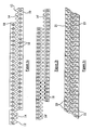
- FIG. 1a two elongate strips (or laminates) 10 are shown.
- the strips 10 are profiled to have peaks 12 and troughs 14 to produce a ⁇ toothed' profile.
- Apertures 16 may be provided in the strip 10 to reduce the mass of the strip 10.
- the strips are preferably formed from metal such as mild steel or stainless steel.
- the troughs 14 in the strips 10 may be shaved to reduce the root radius, at location 18 as shown in Figure 1b .
- the root radius is preferred for strength to thus reduces stress levels.
- a flat bottom profile could be used, provided the loading is acceptable, which would remove the need for further processing to produce the radius 18..
- the strips 10 may be formed from continuous sheet metal on a coil.
- Sheet metal of a desired size in blank form but limited by mass e.g. typically 1-3 tonne coils
- the metal is uncoiled and straightened and "fed” through a continuous process e.g. to profile it.
- the metal can be recoiled onto spools, cut into specified lengths as required or further processed into laminates to form a stairlift rack.
- the continuous process may be split Into manageable chunks. Therefore the profile may first be cut and then restored on to coils. Then, these coils may be taken into the copper brazing continuous process line for amalgamating numerous laminate layers, brazing and cutting to length.
- Figures 1c and 1d show pressed features 20, 22 & 24 that are used to create an interference fit between adjacent strips 10.
- the strips are pressed to create protuberances 20 and corresponding apertures or hollows 22, 24 into which the protuberances 20 are sized to fit.
- the protuberances 20 can be made to fit together back to back if symmetry is required, although this is more complex with regard to tool design.
- the protuberances 20 and hollows 22, 24 help bond the strips 10 together.
- Figure 1c also shows the principal surfaces 21 of the strips 10, which have a small thickness 21.
- Figure 1d is an enlarged view of Figure 1c . which shows the protuberances 20 and hollows 22 (or holes 24) in more detail.
- Figures 2a to 2d represent the stages in the production of a rack 30 for use in a starlift rail.
- Figure 2a represents two elongate strips 10 being pressed from a single, larger strip 26.
- each strip 10 may be produced individually from a single strip or multiple strips may be produced from a wide strip 26.
- two strips 10 are produced, each having a toothed profile.
- the apertures 16 may also be produced at this stage of the continuous process, again using conventional pressing techniques.
- the interference features 20, 22, 24 are pressed into the strips 10.
- the next stage in the process is to re-pltch (i.e. align) the features 22 and 24 and separate the two strips 10 that have been formed - as shown in Figure 2b.
- Figure 2b also shows the further pressing that is performed in order to reduce the root radius of the troughs 14 (as described above in relation to Figure 1b ).
- a brazing material such as copper paste 27, is applied to the surface of the strip 10, for subsequent copper brazing.
- any process creating a union of two materials can be used (e.g. seam welding or laser welding).
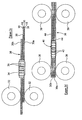
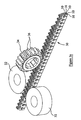
- a plurality 30 of elongate strips 10 are then grouped together- principal surfaces adjacent each other - by a coil feed (as referred to above in connection with the description of the continuous process).
- the strips are driven through pinch rollers 32, as illustrated in Figures 2c and 3a .
- a driven gear 34 ensures that the profile of the strips is pitch-timed to ensure that the peaks 12 and troughs 14' line up with each other.
- the gear 34 has a series of spaced teeth 36 that are sized to fit within the troughs 14' of the stack 30. In this way, the interference features 20, 22, 24 are pressed together.
- the rack is made from two banks of asymmetrical protuberances (viewed from the top of the teeth) staggered so that the interference features 20.
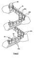
- FIGs 2c and 3a show two groups of laminates 30a, 30b staggered with respect to each other. The significance of this Is described with respect to Figures 6 and 7 below.
- Figures 2d and 3b represent the final induction heating of the stack 30.
- the copper paste is fused to the strips 10 to which lit is adjacent During the copper brazing, the copper flows/wicks in between the interference features or very close surfaces i.e. the primary features 22 & 24.
- the stack 30 of strips or laminates 10 is thus brazed, under pressure by a set of pinch rollers 38, to form a rack 45 (e.g. as shown in Figure 4a ).
- Teeth 42 of a driven gear 40 pitch time the profiled stack 30 during the brazing process.
- Figures 2d and 3b show groups of laminates 30a, 30b aligned with respect to each other - i.e. not staggered. This arrangement will be discussed in further detail with regard to Figure 5 .
- Figure 3b also shows shielding 44, which may be added to the outer surfaces of the stack 30. It is to be noted that the shielding 44 may be provided on one or both sides of the stack 30.
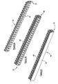
- Figures 4a shows the stack 30 without any shielding
- figure 4b shows the stack with shielding 44 provided along one side
- figure 4c shows the stack 30 with shielding 44 provided on both sides.
- Figure 4a thus represents a finished rack 45, without any shielding, which could be used in a stairlift rail (see e.g. Figure 5 ).
- Figures 4b and 4c represent a finished rack 46 with shielding 44 for use in a stairlift rail (not shown).
- a wheel, gear or roller (not shown) provided within the stairlift carriage is configured to run along the rack 45, 46. The wheel/tooth arrangenment controls the movment of the stairlift along the rack 45, 46.
- the shielding may be brazed to the stack 30, e.g. using copper paste as before.
- the shield 44 may simply be welded on.
- the shield 44 could be dipped on or pressed In to the outer strips 10 of the stack 30, into cavities provided therein e.g. the apertures 16 or other dedicated cavities (not shown).
- Known stairlift rails require machining a bevel into an extruded rack for affixing shielding thereto.
- the above ways of fixing shielding to a laminate rack thus advantageously provide a cost saving, and simplify manufacture, compared with the known rails.
- the shielding is also beneficial from a health and safety point of view.
- the teeth of the stack 30 can be sharp and, if left exposed, could be dangerous. Applying the shielding 44 thus advantageously encompasses the toothed rack and hides the peaks 12 of the stack 30.
- the shielding may also assist in keeping the wheel or gear on the stairlift rack.
- the rack 45 in laminate form could be used in a rail system without the shielding.
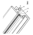
- Figures 5 and 6 show examples of laminate racks 45 provided within a stairlift rail casing 50.
- the rail 50 may be mounted (e.g. bolted) to the treads of stairs (not shown).
- the support rail 50 may typically be formed from extruded aluminium. Brackets 52 of the support rail 50 captivate the laminates 30. In such embodiments, copper brazing would be optional as the captivation within the rail 50 would secure the laminates 10 together and in situ within the rail 50.
- the interference features 20, 22, 24 may, however, be used to help secure the laminates together.
- a stairlift chair (not shown) would be mounted on a carriage which comprises a roller or gear that is driven (e.g. by a motor) to transport the carriage along the rail (e.g. up and down a flight of stairs).
- the stairlift rail 50 of Figure 5 may be formed from a plurality of discrete sections.
- Figure 6 shows an exemplary joint between two stairlift rail sections 50a, 50b.
- the brackets 52 can be used to secure the laminates 10 together and within the rail 50 without the need for copper brazing.
- the laminates 50 may be joined by staggering / overlapping groups of laminates 10 in order to ensure a correct pitch and alignment along the length of the rail 50.
- a first section of stairlift rail 50a comprises a first group of laminates 30a and a second group of laminates 30b staggered with respect to each other.
- a second section of stairlift rail 50b comprises a first group of laminates 30c and a second group of laminates 30d also staggered with respect to each other.
- the staggering of the laminates 30a, 30b of the first rail section 50a is opposite to that of the laminates 30c. 30d of the second rail section 50b. This allows for the laminates 30a, 30c to be aligned end to end and simultaneously for the laminates 30b, 30d to be aligned end to end to effectively form a continuous laminate rack 45.
- the laminates 30b, 30c may be secured together with fastening means such as rivets or pins 54.
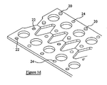
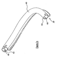
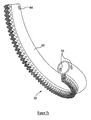
- a curved guide rail section 60 is shown.
- a curved rail 60 may be formed from a straight section (e.g. as described above) by bending the rack on a specially set bending machine (not shown) in order to get the desired curvature (radius and/or helix) and maintain the desired profile alignment. Securing the laminates together by brazing enables the laminated stack 30 to be bent isotropically.
- Embodiments of the invention therefore provide for manufacturing and manipulating a homogeneous rack of substantially uniform thickness from a plurality of elongate strips.
- the stack of laminates 30 - which form the drive rail 60 - may be attached to the rail 60 e.g. by welding.
- the carriage of the stairlift (not shown) is typically mounted around the guide rail 60 and the stairlift (not shown) is moveable along drive rail 30 via a roller or gear (not shown) provided within the stairlift carriage
- One end 62 of the guide rail 60 may be provided with a joint plug, which may be inserted into the end of the rail 60, or may be formed integrally therewith.
- the plug 62 can be inserted into an end 64 of another guide rail section 60.
- Apertures 66 are provided in the guide rail 60.
- a securing member e.g. a bolt (not shown) may be used to secure adjacent sections 60 together via the apertures 66 on the adjacent rail ends 62, 64.
- Differently curved sections 60 may therefore be coupled together in order to form the desired length of rail.
- This arrangement may advantageously be employed in situations where the stairs are not straight, for example, where they bend or curve around a corner.
- the rails 30, 60 may be any length and may bend/curve through any angle Including 90 degrees (for example).
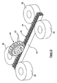
- Figure 8 shows a stairlift 68 mounted in a stairwell 70.
- the stairlift 68 travels along a pair of drive rails 60.
- a wheel, gear and/or roller (not shown) provided within the carriage of the stairlift 68 is configured to run along the drive rails 60.
- the rails 60 comprise a plurality of straight rail sections 60a and curved rail sections 60b.
- Embodiments of the invention thus provide a system that is fully adaptable for any stairwell or set of stairs, whether it is straight or curved or a mixture of each in different locations. Being able to use the same racks for both the straight and curved sections ensures homogeneity of the rack along the entire length of the rail, and provides for smooth transitions at the join of adjacent sections.
Landscapes
- Engineering & Computer Science (AREA)
- Mechanical Engineering (AREA)
- Transportation (AREA)
- Automation & Control Theory (AREA)
- Structural Engineering (AREA)
- General Engineering & Computer Science (AREA)
- Types And Forms Of Lifts (AREA)
- Inorganic Insulating Materials (AREA)
- Load-Engaging Elements For Cranes (AREA)
- Transmission Devices (AREA)
- Gears, Cams (AREA)
Claims (11)
- Procédé de formation d'une crémaillère courbée, le procédé comprenant les étapes ci-dessous :fourniture de plusieurs bandes allongées (10), le bandes étant profilées pour conférer un profil (12, 14) à la crémaillère ;alignement des profils pour former une pile (30) de bandes avec ledit profil ;assemblage desdites plusieurs bandes pour former ladite crémaillère, ladite étape d'assemblage comprenant une ou plusieurs des opérations suivantes : brasage, brasage par induction, brasage par alliage cuivreux, et brasage par interférence, ou soudage par joints ou soudage au laser ; etfléchissement de la crémaillère tout en maintenant la relation de position des bandes adjacentes.
- Procédé selon la revendication 1, comprenant en outre l'étape de profilage desdites bandes (10) pour former plusieurs dents (12).
- Procédé selon l'une quelconque des revendications précédentes, dans lequel l'étape d'assemblage desdites plusieurs bandes pour former ladite crémaillère comprend la formation de structures (20, 22, 24) sur certaines ou sur l'ensemble des bandes (10), pouvant s'engager dans des structures correspondantes sur les bandes qui y sont adjacentes.
- Procédé selon l'une quelconque des revendications précédentes, dans lequel des parties (16) de matériau sont retirées de chacune desdites bandes (10), de sorte à réduire leur masse.
- Procédé de formation d'une crémaillère composite, comprenant l'étape de formation de plusieurs sections de crémaillère selon l'une quelconque des revendications précédentes et de liaison desdites sections de crémaillère les unes aux autres pour former une longueur de crémaillère.
- Crémaillère courbée, comprenant plusieurs bandes allongées (10) assemblées sous forme d'une pile (30) de bandes pour former ladite crémaillère, les bandes étant profilées et les profils (12, 14) étant alignés pour conférer un profil à la crémaillère, les bandes adjacentes étant reliées les unes aux autres et assemblées dans une liaison de deux matériaux fournis par l'un ou plusieurs des processus suivants : brasage, brasage par induction, brasage par alliage cuivreux et brasage par interférence, ou soudage par joints ou soudage au laser.
- Crémaillère selon la revendication 6, dans laquelle les structures (20, 22, 24) sur certaines ou l'ensemble des bandes (10) s'engageant dans des structures correspondantes sur des bandes adjacentes.
- Crémaillère selon les revendications 6 ou 7, dans laquelle chacune desdites bandes profilées comprend plusieurs dents (12).
- Crémaillère composite, comprenant plusieurs sections de crémaillère (50a, 50b) selon l'une quelconque des revendications 6 à 8, lesdites sections de crémaillère étant reliées les unes aux autres pour former une longueur de crémaillère.
- Crémaillère selon l'une quelconque des revendications 6 à 8, ou crémaillère composite selon la revendication 9, dans laquelle ladite crémaillère a une épaisseur uniforme.
- Crémaillère ou crémaillère composite selon l'une quelconque des revendications 7 à 12, dans laquelle ladite crémaillère est appropriée pour une utilisation dans un rail d'ascenseur d'escalier.
Applications Claiming Priority (1)
| Application Number | Priority Date | Filing Date | Title |
|---|---|---|---|
| GBGB0816861.9A GB0816861D0 (en) | 2008-09-15 | 2008-09-15 | Rack and method of forming the same |
Publications (2)
| Publication Number | Publication Date |
|---|---|
| EP2163789A1 EP2163789A1 (fr) | 2010-03-17 |
| EP2163789B1 true EP2163789B1 (fr) | 2011-11-09 |
Family
ID=39930181
Family Applications (1)
| Application Number | Title | Priority Date | Filing Date |
|---|---|---|---|
| EP09252188A Active EP2163789B1 (fr) | 2008-09-15 | 2009-09-15 | Étagère et son procédé de formation |
Country Status (11)
| Country | Link |
|---|---|
| US (1) | US8360336B2 (fr) |
| EP (1) | EP2163789B1 (fr) |
| JP (1) | JP2010089964A (fr) |
| CN (1) | CN101956806B (fr) |
| AT (1) | ATE532994T1 (fr) |
| AU (1) | AU2009215220A1 (fr) |
| CA (1) | CA2678688C (fr) |
| ES (1) | ES2377060T3 (fr) |
| GB (2) | GB0816861D0 (fr) |
| PT (1) | PT2163789E (fr) |
| RU (1) | RU2509242C2 (fr) |
Families Citing this family (16)
| Publication number | Priority date | Publication date | Assignee | Title |
|---|---|---|---|---|
| DE202009016087U1 (de) * | 2009-11-25 | 2010-08-12 | Atlanta Antriebssysteme E. Seidenspinner Gmbh & Co. Kg | Zahnstange mit verbesserter Steifigkeit |
| ITPR20120068A1 (it) * | 2012-10-17 | 2014-04-18 | Domotime S R L | Procedimento per la realizzazione di cremagliere destinate ad automatismi per cancelli |
| ITPD20120331A1 (it) * | 2012-11-07 | 2014-05-08 | Comunello Flii Spa | Cremagliera in particolare per cancello scorrevole e procedimento per la sua realizzazione |
| JP5995791B2 (ja) | 2013-06-24 | 2016-09-21 | ニッタ株式会社 | ラックおよびラックの製造方法 |
| GB2519100A (en) * | 2013-10-09 | 2015-04-15 | Island Mobility Ltd | Stairlift component and kit |
| CN104985411A (zh) * | 2015-08-02 | 2015-10-21 | 衢州市优德工业设计有限公司 | 一种叠层齿轮的加工方法 |
| CN104985412A (zh) * | 2015-08-02 | 2015-10-21 | 衢州市优德工业设计有限公司 | 一种多层齿轮的加工方法 |
| CN105840783B (zh) * | 2016-04-27 | 2018-02-06 | 太仓宝达齿条有限公司 | 一种框架式金属齿条 |
| DE102016012941B4 (de) | 2016-10-28 | 2019-06-06 | Mvo Gmbh Metallverarbeitung Ostalb | Verfahren zur Bearbeitung einer Zahnstange und danach bearbeitete Zahnstange |
| WO2019103612A1 (fr) * | 2017-11-24 | 2019-05-31 | Devi-Group B.V. | Crémaillère pour un guide d'escalier, et procédé de fourniture d'un guide d'escalier comprenant une crémaillère |
| FR3074866B1 (fr) * | 2017-12-13 | 2020-05-29 | Foundation Brakes France Sas | Piece comprenant des dents et des nervures |
| WO2020243233A1 (fr) * | 2019-05-31 | 2020-12-03 | Bruno Independent Living Aids, Inc. | Rail de monte-escalier et son procédé de formation |
| USD933330S1 (en) | 2019-05-31 | 2021-10-12 | Bruno Independent Living Aids, Inc. | Stairlift rail |
| CA3142266A1 (fr) * | 2019-05-31 | 2020-12-03 | Bruno Independent Living Aids, Inc. | Monte-escalier |
| GB2585658B (en) * | 2019-07-09 | 2023-08-16 | Stannah Stairlifts Ltd | Improvements in or relating to stairlifts |
| US11767905B2 (en) * | 2020-08-07 | 2023-09-26 | Ami Industries, Inc. | Laminated rack assembly for powered motion of aircraft seats |
Citations (1)
| Publication number | Priority date | Publication date | Assignee | Title |
|---|---|---|---|---|
| GB976237A (en) * | 1962-11-15 | 1964-11-25 | Bristol Siddeley Engines Ltd | Improvements relating to rotor discs |
Family Cites Families (29)
| Publication number | Priority date | Publication date | Assignee | Title |
|---|---|---|---|---|
| US3670397A (en) * | 1970-02-24 | 1972-06-20 | North American Rockwell | Method of fabricating a laminated metal member |
| US3718052A (en) * | 1971-04-05 | 1973-02-27 | Milwaukee Gear Co | Gear structure and method of making the same |
| US3879026A (en) * | 1973-01-22 | 1975-04-22 | Jr James B Lappin | Universal work holders for assembling curved laminated units |
| US3835676A (en) * | 1973-04-09 | 1974-09-17 | Master Lock Co | Laminated padlock body with incorporated band-forming slab |
| US4570542A (en) * | 1982-05-17 | 1986-02-18 | Weld Tooling Corporation | Ribbon rail systems |
| JPS62136655A (ja) | 1985-12-10 | 1987-06-19 | Fuji Photo Film Co Ltd | ハロゲン化銀写真感光材料の処理方法 |
| JPH0523875Y2 (fr) * | 1986-02-21 | 1993-06-17 | ||
| SU1697990A1 (ru) * | 1987-02-20 | 1991-12-15 | Научно-производственное объединение по комплексному технологическому проектированию станкостроительных предприятий "Оргстанкинпром" | Способ изготовлени зубчатых реек |
| DE3841205A1 (de) | 1988-12-07 | 1990-06-13 | Feintool Int Holding | Verfahren zum herstellen von werkstuecken aus metall |
| RU2049035C1 (ru) * | 1992-04-29 | 1995-11-27 | Карпенков Алексей Иванович | Лестничный подъемник |
| US5439257A (en) * | 1992-07-16 | 1995-08-08 | Nwd International Inc. | Brazed hydraulic fittings with interference fit and method of making same |
| ZA938341B (en) | 1992-08-13 | 1994-06-08 | Roy Constant Wood | Rack for a rack and pinion drive arrangement |
| JP3181115B2 (ja) * | 1992-11-25 | 2001-07-03 | 良忠 越原 | 転動噛み合い駆動機構のラック |
| JPH07277633A (ja) * | 1994-04-08 | 1995-10-24 | Yoshitada Etsuhara | 駆動装置のラック |
| DE19634723C2 (de) | 1996-08-28 | 1999-08-12 | Feintool Int Holding | Verfahren zum Herstellen und Schichten von Bauteilen, sowie eine Vorrichtung dafür |
| DE19740286B4 (de) | 1997-09-13 | 2004-03-18 | Volkswagen Ag | Bauteil, bestehend aus mehreren Flachmateriallagen und Verfahren zu seiner Herstellung |
| US5972476A (en) | 1997-11-21 | 1999-10-26 | Means Industries, Inc. | Laminated parts and method of making same |
| JPH11157765A (ja) * | 1997-11-26 | 1999-06-15 | Daido Kogyo Co Ltd | リニア移動装置 |
| SE515309C2 (sv) | 1999-11-01 | 2001-07-09 | Saab Automobile | Munstycke för tillförsel av ventilationsluft i ett fordon |
| NL1013485C2 (nl) * | 1999-11-04 | 2001-05-07 | Freelift Bv | Trapgeleider. |
| DE19953655A1 (de) | 1999-11-08 | 2001-05-10 | Basf Ag | Goniochromatische Glanzpigmente auf Basis in einer reduzierenden Atmosphäre erhitzter, titandioxidbeschichteter silikatischer Plättchen |
| JP3084778U (ja) * | 2001-09-19 | 2002-03-29 | 日本磁性材工業株式会社 | 積層形動力伝達体 |
| NL1020372C2 (nl) * | 2002-04-12 | 2003-10-14 | Freelift Bv | Geleider voor een traplift. |
| EP1413541A1 (fr) * | 2002-10-22 | 2004-04-28 | BC Lift A/S | Rail de guidage pour ascenseur d'escalier |
| GB2421236B (en) | 2004-11-13 | 2008-08-27 | Stannah Stairlifts Ltd | Improvements in or relating to stairlifts |
| GB2428664B (en) | 2005-07-23 | 2008-12-17 | Stannah Stairlifts Ltd | Improvements in or relating to stairlifts |
| US7481085B2 (en) | 2006-03-16 | 2009-01-27 | Master Lock Company Llc | Padlock |
| US7819304B2 (en) * | 2006-03-23 | 2010-10-26 | Commando Lock LLC | Solid brazed laminate structures |
| US20070269676A1 (en) * | 2006-05-19 | 2007-11-22 | Singer Kevin M | Diffusion barrier layer and method of making the same, and wear resistant article with the diffusion barrier layer and method of making the same |
-
2008
- 2008-09-15 GB GBGB0816861.9A patent/GB0816861D0/en not_active Ceased
-
2009
- 2009-09-14 US US12/559,035 patent/US8360336B2/en active Active
- 2009-09-15 JP JP2009213267A patent/JP2010089964A/ja active Pending
- 2009-09-15 PT PT09252188T patent/PT2163789E/pt unknown
- 2009-09-15 AU AU2009215220A patent/AU2009215220A1/en not_active Abandoned
- 2009-09-15 EP EP09252188A patent/EP2163789B1/fr active Active
- 2009-09-15 ES ES09252188T patent/ES2377060T3/es active Active
- 2009-09-15 GB GB0916169A patent/GB2463376A/en not_active Withdrawn
- 2009-09-15 CN CN200910253046.3A patent/CN101956806B/zh active Active
- 2009-09-15 AT AT09252188T patent/ATE532994T1/de active
- 2009-09-15 CA CA2678688A patent/CA2678688C/fr active Active
- 2009-09-15 RU RU2009134571/11A patent/RU2509242C2/ru not_active IP Right Cessation
Patent Citations (1)
| Publication number | Priority date | Publication date | Assignee | Title |
|---|---|---|---|---|
| GB976237A (en) * | 1962-11-15 | 1964-11-25 | Bristol Siddeley Engines Ltd | Improvements relating to rotor discs |
Also Published As
| Publication number | Publication date |
|---|---|
| EP2163789A1 (fr) | 2010-03-17 |
| ATE532994T1 (de) | 2011-11-15 |
| RU2509242C2 (ru) | 2014-03-10 |
| CN101956806B (zh) | 2014-07-30 |
| CA2678688C (fr) | 2016-07-12 |
| GB2463376A (en) | 2010-03-17 |
| RU2009134571A (ru) | 2011-03-20 |
| AU2009215220A1 (en) | 2010-04-01 |
| GB0916169D0 (en) | 2009-10-28 |
| CN101956806A (zh) | 2011-01-26 |
| GB0816861D0 (en) | 2008-10-22 |
| ES2377060T3 (es) | 2012-03-22 |
| US20100064835A1 (en) | 2010-03-18 |
| US8360336B2 (en) | 2013-01-29 |
| CA2678688A1 (fr) | 2010-03-15 |
| PT2163789E (pt) | 2012-02-08 |
| JP2010089964A (ja) | 2010-04-22 |
Similar Documents
| Publication | Publication Date | Title |
|---|---|---|
| EP2163789B1 (fr) | Étagère et son procédé de formation | |
| CN102389927B (zh) | 蜂窝板制造方法及蜂窝板 | |
| RU2431566C2 (ru) | Способ изготовления изогнутых деталей из термопластичного композиционного материала | |
| RU2569859C2 (ru) | Способ и устройство для изготовления выполненных по индивидуальным требованиям металлических полос | |
| CN106276559B (zh) | 自动扶梯/自动人行道模块化桁架及对其组装的方法 | |
| US20050244667A1 (en) | Hybrid-produced sheet metal element and method of producing same | |
| EP2598277B1 (fr) | Procédé d'assemblage de deux segments de fuselage d'aéronef par soudage par friction-malaxage et d'une plaque de recouvrement | |
| JP6723495B2 (ja) | 端部同士クラッド金属複合材の製造方法 | |
| CN1412456A (zh) | 一种齿轮和齿轮的加工方法 | |
| RU2678115C1 (ru) | Способ обработки вырубкой многослойного железного сердечника и способ изготовления многослойного железного сердечника | |
| EP3109196A1 (fr) | Escalier roulant ou tapis roulant à treillis modulaire et procédé d'assemblage d'un escalier ou tapis roulant | |
| WO2015164353A1 (fr) | Structure multicouche comprenant une feuille extérieure rainurée | |
| DE2432541A1 (de) | Verfahren und vorrichtung zur herstellung von verbundprofilen od.dgl. | |
| WO2013008805A1 (fr) | Châssis de porte | |
| RU2489342C2 (ru) | Ступень эскалатора, способ ее изготовления (варианты) и эскалатор | |
| US20060208534A1 (en) | Construction element and a vehicle frame comprising such a construction element | |
| CN109689556B (zh) | 用于制造平台升降机轨道的方法 | |
| JP6566820B2 (ja) | エスカレータのステップチェーン、エスカレータおよびエスカレータのステップチェーンの組み込み方法 | |
| GB2520652B (en) | Vehicle body structure with camber and method for manufacturing vehicle body structure with camber | |
| JP2002037060A (ja) | 単軌条運搬車の駆動装置 | |
| CN1268527C (zh) | 集装箱侧壁结构的加工方法 | |
| JP2003137488A (ja) | 乗客コンベア | |
| GB2565441B (en) | Rail vehicle body structure with camber | |
| US8136464B1 (en) | C-fast system | |
| JP5943750B2 (ja) | 乗客コンベヤ、及び乗客コンベヤの製造方法 |
Legal Events
| Date | Code | Title | Description |
|---|---|---|---|
| PUAI | Public reference made under article 153(3) epc to a published international application that has entered the european phase |
Free format text: ORIGINAL CODE: 0009012 |
|
| AK | Designated contracting states |
Kind code of ref document: A1 Designated state(s): AT BE BG CH CY CZ DE DK EE ES FI FR GB GR HR HU IE IS IT LI LT LU LV MC MK MT NL NO PL PT RO SE SI SK SM TR |
|
| AX | Request for extension of the european patent |
Extension state: AL BA RS |
|
| 17P | Request for examination filed |
Effective date: 20100816 |
|
| 17Q | First examination report despatched |
Effective date: 20100914 |
|
| GRAP | Despatch of communication of intention to grant a patent |
Free format text: ORIGINAL CODE: EPIDOSNIGR1 |
|
| GRAS | Grant fee paid |
Free format text: ORIGINAL CODE: EPIDOSNIGR3 |
|
| GRAA | (expected) grant |
Free format text: ORIGINAL CODE: 0009210 |
|
| AK | Designated contracting states |
Kind code of ref document: B1 Designated state(s): AT BE BG CH CY CZ DE DK EE ES FI FR GB GR HR HU IE IS IT LI LT LU LV MC MK MT NL NO PL PT RO SE SI SK SM TR |
|
| REG | Reference to a national code |
Ref country code: GB Ref legal event code: FG4D |
|
| REG | Reference to a national code |
Ref country code: CH Ref legal event code: EP |
|
| REG | Reference to a national code |
Ref country code: IE Ref legal event code: FG4D |
|
| REG | Reference to a national code |
Ref country code: DE Ref legal event code: R096 Ref document number: 602009003592 Country of ref document: DE Effective date: 20120119 |
|
| REG | Reference to a national code |
Ref country code: PT Ref legal event code: SC4A Free format text: AVAILABILITY OF NATIONAL TRANSLATION Effective date: 20120131 |
|
| REG | Reference to a national code |
Ref country code: NL Ref legal event code: T3 |
|
| REG | Reference to a national code |
Ref country code: ES Ref legal event code: FG2A Ref document number: 2377060 Country of ref document: ES Kind code of ref document: T3 Effective date: 20120322 |
|
| LTIE | Lt: invalidation of european patent or patent extension |
Effective date: 20111109 |
|
| PG25 | Lapsed in a contracting state [announced via postgrant information from national office to epo] |
Ref country code: LT Free format text: LAPSE BECAUSE OF FAILURE TO SUBMIT A TRANSLATION OF THE DESCRIPTION OR TO PAY THE FEE WITHIN THE PRESCRIBED TIME-LIMIT Effective date: 20111109 Ref country code: NO Free format text: LAPSE BECAUSE OF FAILURE TO SUBMIT A TRANSLATION OF THE DESCRIPTION OR TO PAY THE FEE WITHIN THE PRESCRIBED TIME-LIMIT Effective date: 20120209 Ref country code: IS Free format text: LAPSE BECAUSE OF FAILURE TO SUBMIT A TRANSLATION OF THE DESCRIPTION OR TO PAY THE FEE WITHIN THE PRESCRIBED TIME-LIMIT Effective date: 20120309 |
|
| PG25 | Lapsed in a contracting state [announced via postgrant information from national office to epo] |
Ref country code: LV Free format text: LAPSE BECAUSE OF FAILURE TO SUBMIT A TRANSLATION OF THE DESCRIPTION OR TO PAY THE FEE WITHIN THE PRESCRIBED TIME-LIMIT Effective date: 20111109 Ref country code: HR Free format text: LAPSE BECAUSE OF FAILURE TO SUBMIT A TRANSLATION OF THE DESCRIPTION OR TO PAY THE FEE WITHIN THE PRESCRIBED TIME-LIMIT Effective date: 20111109 Ref country code: SI Free format text: LAPSE BECAUSE OF FAILURE TO SUBMIT A TRANSLATION OF THE DESCRIPTION OR TO PAY THE FEE WITHIN THE PRESCRIBED TIME-LIMIT Effective date: 20111109 Ref country code: SE Free format text: LAPSE BECAUSE OF FAILURE TO SUBMIT A TRANSLATION OF THE DESCRIPTION OR TO PAY THE FEE WITHIN THE PRESCRIBED TIME-LIMIT Effective date: 20111109 Ref country code: PL Free format text: LAPSE BECAUSE OF FAILURE TO SUBMIT A TRANSLATION OF THE DESCRIPTION OR TO PAY THE FEE WITHIN THE PRESCRIBED TIME-LIMIT Effective date: 20111109 Ref country code: GR Free format text: LAPSE BECAUSE OF FAILURE TO SUBMIT A TRANSLATION OF THE DESCRIPTION OR TO PAY THE FEE WITHIN THE PRESCRIBED TIME-LIMIT Effective date: 20120210 |
|
| PG25 | Lapsed in a contracting state [announced via postgrant information from national office to epo] |
Ref country code: CY Free format text: LAPSE BECAUSE OF FAILURE TO SUBMIT A TRANSLATION OF THE DESCRIPTION OR TO PAY THE FEE WITHIN THE PRESCRIBED TIME-LIMIT Effective date: 20111109 |
|
| PG25 | Lapsed in a contracting state [announced via postgrant information from national office to epo] |
Ref country code: CZ Free format text: LAPSE BECAUSE OF FAILURE TO SUBMIT A TRANSLATION OF THE DESCRIPTION OR TO PAY THE FEE WITHIN THE PRESCRIBED TIME-LIMIT Effective date: 20111109 Ref country code: EE Free format text: LAPSE BECAUSE OF FAILURE TO SUBMIT A TRANSLATION OF THE DESCRIPTION OR TO PAY THE FEE WITHIN THE PRESCRIBED TIME-LIMIT Effective date: 20111109 Ref country code: SK Free format text: LAPSE BECAUSE OF FAILURE TO SUBMIT A TRANSLATION OF THE DESCRIPTION OR TO PAY THE FEE WITHIN THE PRESCRIBED TIME-LIMIT Effective date: 20111109 Ref country code: DK Free format text: LAPSE BECAUSE OF FAILURE TO SUBMIT A TRANSLATION OF THE DESCRIPTION OR TO PAY THE FEE WITHIN THE PRESCRIBED TIME-LIMIT Effective date: 20111109 Ref country code: BG Free format text: LAPSE BECAUSE OF FAILURE TO SUBMIT A TRANSLATION OF THE DESCRIPTION OR TO PAY THE FEE WITHIN THE PRESCRIBED TIME-LIMIT Effective date: 20120209 |
|
| PG25 | Lapsed in a contracting state [announced via postgrant information from national office to epo] |
Ref country code: RO Free format text: LAPSE BECAUSE OF FAILURE TO SUBMIT A TRANSLATION OF THE DESCRIPTION OR TO PAY THE FEE WITHIN THE PRESCRIBED TIME-LIMIT Effective date: 20111109 |
|
| PLBE | No opposition filed within time limit |
Free format text: ORIGINAL CODE: 0009261 |
|
| STAA | Information on the status of an ep patent application or granted ep patent |
Free format text: STATUS: NO OPPOSITION FILED WITHIN TIME LIMIT |
|
| REG | Reference to a national code |
Ref country code: AT Ref legal event code: MK05 Ref document number: 532994 Country of ref document: AT Kind code of ref document: T Effective date: 20111109 |
|
| 26N | No opposition filed |
Effective date: 20120810 |
|
| REG | Reference to a national code |
Ref country code: DE Ref legal event code: R097 Ref document number: 602009003592 Country of ref document: DE Effective date: 20120810 |
|
| PG25 | Lapsed in a contracting state [announced via postgrant information from national office to epo] |
Ref country code: AT Free format text: LAPSE BECAUSE OF FAILURE TO SUBMIT A TRANSLATION OF THE DESCRIPTION OR TO PAY THE FEE WITHIN THE PRESCRIBED TIME-LIMIT Effective date: 20111109 |
|
| PG25 | Lapsed in a contracting state [announced via postgrant information from national office to epo] |
Ref country code: MC Free format text: LAPSE BECAUSE OF NON-PAYMENT OF DUE FEES Effective date: 20120930 |
|
| REG | Reference to a national code |
Ref country code: IE Ref legal event code: MM4A |
|
| PG25 | Lapsed in a contracting state [announced via postgrant information from national office to epo] |
Ref country code: FI Free format text: LAPSE BECAUSE OF FAILURE TO SUBMIT A TRANSLATION OF THE DESCRIPTION OR TO PAY THE FEE WITHIN THE PRESCRIBED TIME-LIMIT Effective date: 20111109 |
|
| PG25 | Lapsed in a contracting state [announced via postgrant information from national office to epo] |
Ref country code: IE Free format text: LAPSE BECAUSE OF NON-PAYMENT OF DUE FEES Effective date: 20120915 |
|
| PG25 | Lapsed in a contracting state [announced via postgrant information from national office to epo] |
Ref country code: MT Free format text: LAPSE BECAUSE OF FAILURE TO SUBMIT A TRANSLATION OF THE DESCRIPTION OR TO PAY THE FEE WITHIN THE PRESCRIBED TIME-LIMIT Effective date: 20111109 |
|
| PG25 | Lapsed in a contracting state [announced via postgrant information from national office to epo] |
Ref country code: TR Free format text: LAPSE BECAUSE OF FAILURE TO SUBMIT A TRANSLATION OF THE DESCRIPTION OR TO PAY THE FEE WITHIN THE PRESCRIBED TIME-LIMIT Effective date: 20111109 |
|
| REG | Reference to a national code |
Ref country code: CH Ref legal event code: PL |
|
| PG25 | Lapsed in a contracting state [announced via postgrant information from national office to epo] |
Ref country code: SM Free format text: LAPSE BECAUSE OF FAILURE TO SUBMIT A TRANSLATION OF THE DESCRIPTION OR TO PAY THE FEE WITHIN THE PRESCRIBED TIME-LIMIT Effective date: 20111109 Ref country code: LU Free format text: LAPSE BECAUSE OF NON-PAYMENT OF DUE FEES Effective date: 20120915 |
|
| PG25 | Lapsed in a contracting state [announced via postgrant information from national office to epo] |
Ref country code: CH Free format text: LAPSE BECAUSE OF NON-PAYMENT OF DUE FEES Effective date: 20130930 Ref country code: LI Free format text: LAPSE BECAUSE OF NON-PAYMENT OF DUE FEES Effective date: 20130930 Ref country code: HU Free format text: LAPSE BECAUSE OF FAILURE TO SUBMIT A TRANSLATION OF THE DESCRIPTION OR TO PAY THE FEE WITHIN THE PRESCRIBED TIME-LIMIT Effective date: 20090915 |
|
| PG25 | Lapsed in a contracting state [announced via postgrant information from national office to epo] |
Ref country code: MK Free format text: LAPSE BECAUSE OF FAILURE TO SUBMIT A TRANSLATION OF THE DESCRIPTION OR TO PAY THE FEE WITHIN THE PRESCRIBED TIME-LIMIT Effective date: 20111109 |
|
| REG | Reference to a national code |
Ref country code: FR Ref legal event code: PLFP Year of fee payment: 8 |
|
| REG | Reference to a national code |
Ref country code: FR Ref legal event code: PLFP Year of fee payment: 9 |
|
| PGFP | Annual fee paid to national office [announced via postgrant information from national office to epo] |
Ref country code: BE Payment date: 20170926 Year of fee payment: 9 Ref country code: PT Payment date: 20170713 Year of fee payment: 9 Ref country code: NL Payment date: 20170927 Year of fee payment: 9 |
|
| REG | Reference to a national code |
Ref country code: FR Ref legal event code: PLFP Year of fee payment: 10 |
|
| REG | Reference to a national code |
Ref country code: NL Ref legal event code: MM Effective date: 20181001 |
|
| PG25 | Lapsed in a contracting state [announced via postgrant information from national office to epo] |
Ref country code: PT Free format text: LAPSE BECAUSE OF NON-PAYMENT OF DUE FEES Effective date: 20190315 |
|
| REG | Reference to a national code |
Ref country code: BE Ref legal event code: MM Effective date: 20180930 |
|
| PG25 | Lapsed in a contracting state [announced via postgrant information from national office to epo] |
Ref country code: NL Free format text: LAPSE BECAUSE OF NON-PAYMENT OF DUE FEES Effective date: 20181001 |
|
| PG25 | Lapsed in a contracting state [announced via postgrant information from national office to epo] |
Ref country code: BE Free format text: LAPSE BECAUSE OF NON-PAYMENT OF DUE FEES Effective date: 20180930 |
|
| P01 | Opt-out of the competence of the unified patent court (upc) registered |
Effective date: 20230522 |
|
| PGFP | Annual fee paid to national office [announced via postgrant information from national office to epo] |
Ref country code: GB Payment date: 20230921 Year of fee payment: 15 |
|
| PGFP | Annual fee paid to national office [announced via postgrant information from national office to epo] |
Ref country code: FR Payment date: 20230918 Year of fee payment: 15 Ref country code: DE Payment date: 20230919 Year of fee payment: 15 |
|
| PGFP | Annual fee paid to national office [announced via postgrant information from national office to epo] |
Ref country code: ES Payment date: 20231019 Year of fee payment: 15 |
|
| PGFP | Annual fee paid to national office [announced via postgrant information from national office to epo] |
Ref country code: IT Payment date: 20230929 Year of fee payment: 15 |