EP2162811B1 - Procédé et dispositif pour influencer la dynamique transversale d'un véhicule - Google Patents
Procédé et dispositif pour influencer la dynamique transversale d'un véhicule Download PDFInfo
- Publication number
- EP2162811B1 EP2162811B1 EP08759014A EP08759014A EP2162811B1 EP 2162811 B1 EP2162811 B1 EP 2162811B1 EP 08759014 A EP08759014 A EP 08759014A EP 08759014 A EP08759014 A EP 08759014A EP 2162811 B1 EP2162811 B1 EP 2162811B1
- Authority
- EP
- European Patent Office
- Prior art keywords
- vehicle
- threshold value
- intervention
- equal
- variable
- Prior art date
- Legal status (The legal status is an assumption and is not a legal conclusion. Google has not performed a legal analysis and makes no representation as to the accuracy of the status listed.)
- Not-in-force
Links
- 238000000034 method Methods 0.000 title claims abstract description 42
- 230000001133 acceleration Effects 0.000 claims description 12
- 230000001419 dependent effect Effects 0.000 claims description 6
- 230000001960 triggered effect Effects 0.000 claims description 3
- 230000004913 activation Effects 0.000 description 10
- 230000008569 process Effects 0.000 description 7
- 239000000725 suspension Substances 0.000 description 5
- 230000003213 activating effect Effects 0.000 description 4
- 230000009849 deactivation Effects 0.000 description 4
- 238000010586 diagram Methods 0.000 description 4
- 230000000694 effects Effects 0.000 description 4
- 230000033001 locomotion Effects 0.000 description 4
- 230000008859 change Effects 0.000 description 2
- 125000004122 cyclic group Chemical group 0.000 description 1
- 230000009467 reduction Effects 0.000 description 1
- 230000011664 signaling Effects 0.000 description 1
- 230000006641 stabilisation Effects 0.000 description 1
- 238000011105 stabilization Methods 0.000 description 1
- 239000003381 stabilizer Substances 0.000 description 1
Images


Classifications
-
- B—PERFORMING OPERATIONS; TRANSPORTING
- B60—VEHICLES IN GENERAL
- B60T—VEHICLE BRAKE CONTROL SYSTEMS OR PARTS THEREOF; BRAKE CONTROL SYSTEMS OR PARTS THEREOF, IN GENERAL; ARRANGEMENT OF BRAKING ELEMENTS ON VEHICLES IN GENERAL; PORTABLE DEVICES FOR PREVENTING UNWANTED MOVEMENT OF VEHICLES; VEHICLE MODIFICATIONS TO FACILITATE COOLING OF BRAKES
- B60T8/00—Arrangements for adjusting wheel-braking force to meet varying vehicular or ground-surface conditions, e.g. limiting or varying distribution of braking force
- B60T8/17—Using electrical or electronic regulation means to control braking
- B60T8/1755—Brake regulation specially adapted to control the stability of the vehicle, e.g. taking into account yaw rate or transverse acceleration in a curve
- B60T8/17555—Brake regulation specially adapted to control the stability of the vehicle, e.g. taking into account yaw rate or transverse acceleration in a curve specially adapted for enhancing driver or passenger comfort, e.g. soft intervention or pre-actuation strategies
-
- B—PERFORMING OPERATIONS; TRANSPORTING
- B60—VEHICLES IN GENERAL
- B60T—VEHICLE BRAKE CONTROL SYSTEMS OR PARTS THEREOF; BRAKE CONTROL SYSTEMS OR PARTS THEREOF, IN GENERAL; ARRANGEMENT OF BRAKING ELEMENTS ON VEHICLES IN GENERAL; PORTABLE DEVICES FOR PREVENTING UNWANTED MOVEMENT OF VEHICLES; VEHICLE MODIFICATIONS TO FACILITATE COOLING OF BRAKES
- B60T8/00—Arrangements for adjusting wheel-braking force to meet varying vehicular or ground-surface conditions, e.g. limiting or varying distribution of braking force
- B60T8/17—Using electrical or electronic regulation means to control braking
- B60T8/1755—Brake regulation specially adapted to control the stability of the vehicle, e.g. taking into account yaw rate or transverse acceleration in a curve
- B60T8/17551—Brake regulation specially adapted to control the stability of the vehicle, e.g. taking into account yaw rate or transverse acceleration in a curve determining control parameters related to vehicle stability used in the regulation, e.g. by calculations involving measured or detected parameters
Definitions
- the invention relates to a method for influencing the lateral dynamics of a vehicle, in particular of a motor vehicle, and a lateral dynamics influencing device, wherein a transverse dynamic interference variable acting on the vehicle and in particular the vehicle structure is determined by means of a disturbance variable determination device and a brake engagement is brought about.
- the present invention relates to a lateral dynamics influencing device for a vehicle, in particular a motor vehicle, with a disturbance determination device for determining a transverse dynamic disturbance variable acting on the vehicle and in particular the vehicle body.
- a device for influencing the transverse dynamics of a motor vehicle in the form of a parallel drive control system is known. It will be during a parallel journey measured a distance to a guide device and made in distance changes, for example by crosswinds, by braking a direction correction. It should be regarded in particular as disadvantageous that the device described can be used only in the presence of said guide device.
- a method and a device for influencing the lateral dynamics of a vehicle in which or is responded to a detected disturbance of the lateral dynamics by means of a change in the wheel contact force of at least one vehicle wheel.
- a method for driving state stabilization control is known, wherein the control is based on the implementation of brake interventions and wherein the control is activated when a driving state actual value is outside a tolerance band and when, as an additional criterion, the slip angle exceeds a predetermined amount.
- the invention is based on the object, starting from a method and a device of the type mentioned in each case to specify a method or a device, so that an increase in driving safety is achieved in different driving situations.
- the driver must not react according to the invention in a sudden disturbance of the vehicle lateral dynamics with a possibly uncontrolled steering movement, but it comes to an automatic compensation or correction of Disturbance, whereby the driving safety is increased. This is also done according to the invention, without depending on certain external devices, such as the above-mentioned guide device.
- the chassis intervention is only triggered when the intervention condition is met. In this way, driving situations in which a chassis intervention, in particular a braking intervention, would not have precluded driving safety. Chassis interventions that could reduce driving safety are not carried out.
- the engagement condition is satisfied only when the amount of the steering wheel angle is less than or equal to a steering wheel angle threshold and / or when the amount of steering wheel angular velocity is less than or equal to a steering wheel angular velocity threshold.
- the engagement condition can be satisfied only when the amount of the stationary lateral acceleration is less than or equal to a lateral acceleration threshold. In this way, chassis interventions when driving dynamic maneuvers, for example when driving through curves with correspondingly small curve radii, are avoided. It is thus achieved a longitudinal speed-dependent steering wheel angle limitation.
- an intervention determination value can be determined which describes the magnitude of the transverse dynamics interference variable or the magnitude of the yawing moment determined with the aid of the transverse dynamics interference variable or the value of another variable correlating with one of the two variables in order to compensate for the cross interference.
- amounts of the intervention determination value below a lower threshold value
- only one of the wheels, in particular one of the non-steerable wheels can be braked via an respectively associated braking device.
- amounts of engagement engagement value greater than or equal to the lower threshold and less than an upper threshold only one of the steerable wheels on the front axle can be braked via the respective associated brake device.
- both wheels of the same vehicle side can be braked via the respective associated brake device. In this way, the braking intervention can be adapted to the intensity of the transverse dynamics disturbance caused by the transverse dynamics disturbance variable.
- Fig. 1 shows a schematic representation of a motor vehicle with an embodiment of the device according to the invention.
- the motor vehicle 1 has four wheels 2.1-2.4, which are each in operative connection with an associated brake unit 3.1-3.4.
- Each of the brake units 3.1-3.4 is designed to brake the respective associated wheel 2.1-2.4 of the vehicle 1 and can be controlled independently of the respective other brake units individually. As a result, different levels of braking forces or braking effects on the individual wheels 2.1-2.4 can be achieved.
- a corresponding actuation of the brake unit with 2.1-2.4 is also referred to as "brake intervention".
- a brake force activation device 4 is provided according to the invention, which is in operative signaling connection with the brake units 3.1-3.4.
- the braking force activating device 4 in turn is in operative connection with a control unit 5 which has a disturbance determination device 5.1 - which is also referred to herein as "disturbance observer" - and a checking device 5.2, wherein the control unit 5 with a number of sensors 6.1-6 .n is connected and
- the sensors 6.1-6.n are used to determine actual driving dynamics of the vehicle 1, such as an actual yaw rate, a vehicle longitudinal speed, a steering wheel angle, a steering angle or an actual lateral acceleration.
- Corresponding sensor signals in SS1-SSn are transmitted from the sensors 6.1-6.n to the control unit 5 and consequently to the disturbance variable determination device 5.1 and the checking device 5.2.
- the disturbance variable determination device 5.1 determines from the actual variables of the vehicle 1 a transverse dynamics disturbance variable of the vehicle as described in the German patent application 10 2004 017 638 is explained in detail. In this way, the disturbance-determining device 5.1 can be used in particular for determining the disturbing effect of side wind SW acting on the vehicle 1 or on its vehicle body and the influencing of the transverse vehicle dynamics caused thereby.
- the German patent application 10 2004 017 638 is expressly referred to.
- the disturbance variable determination device 5.1 generates an interference quantity signal SGS, which is transmitted to the checking device 5.2.
- SGS interference quantity signal
- a corresponding engagement signal BES is transmitted to the brake force activating device 4.
- the latter activates, depending on the intervention signal BES, at least one or more of the brake units 3.1-3.4 by means of corresponding brake force activation signals BKAS1-BKAS4.
- the brake force activation signals BKAS1-BKAS4 are also transmitted to the control unit 5 and in particular to the disturbance variable determination device 5.1, to the braking torque caused on one side of the vehicle and the resulting influence on the yaw motion of the vehicle to take into account in the determination of the transverse dynamics disturbance.
- the braking intervention is performed on at least one wheel 2.1, 2.4 or 2.2, 2.3 of a vehicle side, in order to generate a yawing moment directed against the transverse disturbance.
- the braking operation is performed as comfortable as possible for the driver, only the corresponding non-steerable wheel 2.1 or 2.2 at the rear axle of the vehicle can be braked exclusively or at least in a first braking engagement stage, so that any noticeable repercussions on the steering wheel of the vehicle 1 remain as small as possible .
- the extent to which any feedback is caused by wheel-specific braking of a steerable wheel 2.3 or 2.4 on the steering wheel depends on the type of vehicle and its chassis design.
- Whether the braking intervention takes place on a steerable wheel 2.3 or 2.4 and / or on a non-steerable wheel 2.1 or 2.2 is individually adapted to the vehicle type. For vehicle types in which only slight effects on the steering wheel occur when braking a steerable wheel 2.3 or 2.4, therefore, alternatively or in addition to the non-steerable rear wheel 2.1 or 2.2 and the steerable wheel 2.3 or 2.4 the same vehicle side to compensate for cross-interference be braked.
- the braking force distribution between steerable front wheel 2.3 or 2.4 and rear wheel 2.2 or 2.1 on this side of the vehicle can be specified depending on the vehicle and / or adjusted depending on the driving situation.
- the braking force distribution between steerable front wheel 2.3 or 2.4 and non-steerable rear wheel 2.2 or 2.1 may depend on parameters such as the amount of lateral dynamics disturbance, steering angle, longitudinal velocity, lateral acceleration, yaw rate, or other longitudinal and lateral dynamic driving state quantities.
- the right rear wheel can be braked 2.2 and / or the right front wheel 2.3, thereby generating a yaw moment on the vehicle 1 about its vertical axis in a clockwise direction.
- the directions are exactly the opposite, in which case the left front wheel 2.4 and / or the left rear wheel 2.1 are braked.
- the disturbance of the lateral dynamics by the side wind SW is at least partially compensated.
- the disturbance determination device 5 and / or the braking force activating device 4 is designed to determine a required braking force on one or more wheels 2.1-2.4 of the vehicle 1 by means of a suitable method or model, in order - as already mentioned - to compensate for the occurred disturbance of the vehicle lateral dynamics.
- the driver of the vehicle 1 is therefore assisted in compensating for a disturbance of the vehicle lateral dynamics, such as, for example, a crosswind wind.
- the occurring disturbance of the lateral dynamics is automatically reduced or complete compensated. This contributes to an increase in driving safety.
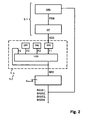
- FIG. 2 shows a block diagram of an embodiment of the inventive method for influencing the lateral dynamics of a vehicle, in particular the motor vehicle 1 according to Fig. 1 ,
- the method according to the invention begins with the determination of the transverse dynamics disturbance variable FSW in an observer block OBS on the basis of the vehicle dynamic actual variables of the vehicle measured by the sensors 6.1 to 6.n and on the basis of the brake force activation signals BKAS1-BKAS4.
- the method used in the observer block OBS to determine the transverse dynamics disturbance variable FSW is in the DE 10 2004 017 638 A1 described in this context.
- the transverse dynamic interference quantity FSW determined in this way by means of the observer block OBS is then high-pass filtered in a high-pass filter HP in order to filter out stationary portions of the transverse dynamics interference variable FSW, which are not to be taken into account in the following method. Only dynamic portions of the lateral dynamics disturbance variable FSW are considered in the further procedure.
- the high-pass filter HP generates the high-pass filtered transverse dynamics disturbance, which in the present case corresponds to the disturbance variable signal SGS, which is transmitted to the checking device 5.2 of the control unit 5.
- the intervention condition has a plurality of criteria which, according to the example, must be met individually in order to fulfill the engagement condition. These criteria serve to exclude driving situations in which no automatic braking intervention is to be caused.
- the intervention signal BES is determined in a logic block LOG, which is fed back as the fourth flag F4 to an input of the logic block LOG.
- the logic block both the values of the flags F1, F2, F3, F4 which are present in the current process cycle n and also the values of the flags F1, F2, F3, F4 from the preceding process cycle n-1 are used to determine the intervention signal BES.
- the values of the first flag F1, the second flag F2 and the fourth flag F4 from the previous method cycle are taken into account.
- Each row of the table corresponds to a combination of states that triggers or maintains a brake in the current cycle of the process: F2 (n-1) F2 (n) F1 (n-1) F1 (n) F3 (n) F4 (n-1) 0
- a new cycle begins analogous to the process cycle described above.
- the values F1, F2, F3, F4 for the preceding process cycle are respectively given a starting value F1 (start), F2 (start), F3 (start) and F4 (start), so that the method also can work on the first cycle, eg when starting the vehicle.
- start a starting value
- the exemplary embodiment described here carries out a braking intervention as a chassis intervention in order to counteract the transverse dynamics disturbance.
Claims (16)
- Procédé pour influer sur la dynamique transversale d'un véhicule (1) ; selon ce procédé, une grandeur de perturbation de dynamique transversale agissant sur le véhicule (1) et en particulier sur la carrosserie du véhicule (1) est détectée et une vérification est effectuée pour savoir si une condition d'intervention définie est remplie lorsque la condition d'intervention est satisfaite, une intervention sur le véhicule pour influencer la dynamique transversale est effectuée et la condition d'intervention est remplie lorsque la valeur d'une grandeur perturbatrice de dynamique transversale déterminée est supérieure à une valeur seuil de grandeur de perturbation, caractérisé en ce que la condition d'intervention est remplie lorsqu'en outre soit un des critères suivants soit un groupe de plusieurs des facteurs suivants est respecté :- la vitesse longitudinale du véhicule est supérieure à une valeur seuil de vitesse longitudinale du véhicule ;- le taux de lacet réel détecté par capteur est inférieur ou égal à un taux de lacet actuel calculé ;- une grandeur de différence de glissement représentant la différence de glissement entre deux roues du véhicule est inférieure ou égale à une valeur seuil de différence de glissement.
- Procédé selon la revendication 1, caractérisé en ce que la condition d'intervention est remplie lorsqu'une grandeur de couple de freinage représentant un couple de freinage occasionné par un freinage du conducteur est inférieure ou égale à une valeur seuil de couple de freinage.
- Procédé selon la revendication 1 ou 2, caractérisé en ce que la condition d'intervention est remplie lorsqu'au moins un des critères suivants est respecté :- une grandeur de débattement représentant le débattement actuel d'un ressort de suspension d'une roue du véhicule est inférieure ou égale à une valeur seuil ;- une grandeur de débattement différentiel représentant la différence entre les débattements actuels sur les deux ressorts de suspension d'un essieu du véhicule est inférieure ou égale à une valeur seuil de débattement différentiel ;
- Procédé selon l'une quelconque des revendications précédentes, caractérisé en ce que la condition d'intervention est remplie lorsque la valeur de l'angle du volant est inférieure ou égale à la valeur seuil d'angle du volant et / ou lorsque la valeur de la vitesse angulaire de volant est inférieure ou égale à une valeur seuil de vitesse angulaire de volant.
- Procédé selon l'une quelconque des revendications précédentes, caractérisé en ce que la condition d'intervention est remplie lorsque la valeur de l'accélération transversale stationnaire est inférieure ou égale à une valeur seuil.
- Procédé selon l'une quelconque des revendications précédentes, caractérisé en ce qu'un vent latéral côté (SW) agissant sur la carrosserie du véhicule (1) est détecté au moyen d'un dispositif de détermination (5) de grandeur de perturbation et en ce qu'une perturbation correspondante de la dynamique transversale du véhicule (1) est au moins partiellement compensée par l'intervention sur la suspension.
- Procédé selon l'une quelconque des revendications précédentes, caractérisé en ce qu'est déterminée une valeur de détermination d'intervention qui représente la valeur de la grandeur de perturbation de la dynamique transversale ou la valeur du couple de lacet déterminé au moyen de la grandeur de perturbation de la dynamique transversale devant être réglée pour compenser la perturbation transversale ou la valeur d'une autre grandeur en corrélation avec l'une des deux grandeurs.
- Procédé selon l'une quelconque des revendications précédentes, caractérisé en ce qu'une intervention sur la suspension est effectuée comme- une intervention de freinage sur l'une ou plusieurs roues (2.1 - 2.4) et / ou- une influence de freinage des forces de contact de roues sur l'une ou plusieurs roues (2.1 - 2.4) et / ou- une influence du servocouple d'un servomoteur d'un système de direction assistée et / ou- une modification d'un ou de plusieurs couple d'entraînement de roue sur une ou plusieurs roues (2.1 - 2.4).
- Procédé selon la revendication 8 en relation avec la revendication 7, caractérisé en ce qu'en présence de valeurs de détermination d'intervention inférieures à une valeur seuil inférieure uniquement une des roues (2.1 - 2.4) en particulier une des roues non motrices (2.1 ou 2.2) est freinée par le dispositif de freinage concerné (3.1 - 3.4).
- Procédé selon la revendication 8 ou 9 en relation avec la revendication 7, caractérisé en ce qu'en présence de valeurs de détermination d'intervention supérieures ou égales à la valeur seuil inférieure et inférieure à une valeur seuil supérieure, uniquement une des roues motrices (2.3 ou 2.4) de l'essieu avant est freinée par le dispositif de freinage concerné (3.3 ou 3.4).
- Procédé selon l'une quelconque des revendications 9 à 10 en relation avec la revendication 7, caractérisé en ce qu'en présence de valeurs de détermination d'intervention supérieures ou égales à la valeur seuil supérieure les deux roues (2.1, 2.4 ou 2.2, 2.3) du même côté du véhicule sont freinées par le dispositif de freinage concerné (3.1, 3.4 ou 3.2, 3.3).
- Procédé selon la revendication 8 en relation avec la revendication 7, caractérisé en ce que les deux roues (2.1, 2.4 ou 2.2, 2.3) du même côté de véhicule sont freinées par le dispositif de freinage concerné (3.1, 3.4 ou 3.2, 3.3), la distribution de la force de freinage entre la roue motrice (2.3 ou 2.4) et la roue correspondante non motrice (2.2 ou 2.1) du même côté de véhicule est définie en fonction de paramètre et en particulier en fonction du véhicule et / ou peut être réglée en fonction de la situation de conduite.
- Procédé selon l'une quelconque des revendications précédentes, caractérisé en ce qu'une intervention sur la suspension déclenchée est de nouveau achevée une fois que la condition d'intervention est remplie.- lorsque la grandeur de couple de freinage représentant le couple de freinage occasionné par un freinage du conducteur est supérieure à la valeur seuil de couple de freinage et / ou- lorsque la valeur angulaire du volant est supérieure à une valeur seuil et / ou- lorsque la valeur de la vitesse angulaire du volant est supérieure à une valeur seuil.
- Procédé selon l'une quelconque des revendications précédentes, caractérisé en ce que la grandeur de perturbation de la dynamique transversale est filtrée au moyen d'un filtre passe-haut avant le contrôle de la condition d'intervention.
- Dispositif permettant d'influer sur la dynamique transversale pour un véhicule (1) doté d'un dispositif de détermination de la grandeur de perturbation (5.1) pour déterminer une grandeur de perturbation de la dynamique transversale agissant sur le véhicule (1) et en particulier sur la carrosserie du véhicule et d'un dispositif de contrôle (5.2) qui sert à contrôler si une condition d'intervention définie est remplie, en cas de condition d'intervention remplie, une intervention sur la suspension pour influencer la dynamique transversale est effectuée, et la condition d'intervention est remplie lorsque la valeur de la grandeur de perturbation de la dynamique transversale détectée est supérieure à une valeur seuil caractérisé en ce que la condition d'intervention est remplie lorsqu'en outre soit un des critères suivants ou soit un groupe de plusieurs des critères suivants est respecté :- la vitesse longitudinale du véhicule est supérieure à une valeur seuil de vitesse longitudinale du véhicule ;- le taux de lacet réel détecté par capteur est inférieur ou égal à un taux de lacet actuel calculé ;- une grandeur de différence de glissement représentant la différence de glissement entre deux roues du véhicule est inférieure ou égale à une valeur seuil de différence de glissement.
- Dispositif permettant d'influencer la dynamique transversale pour un véhicule (1), selon la revendication 15, caractérisé en ce que la condition d'intervention est remplie lorsqu'en plus soit un des critères suivants soit un groupe de plusieurs critères suivants est respecté :- une grandeur de couple de freinage représentant le couple de freinage occasionné par un freinage du conducteur est inférieure ou égale à une valeur seuil de couple de freinage ;- une grandeur de débattement représentant le débattement actuel d'un ressort de suspension d'une roue du véhicule est inférieure ou égale à une valeur seuil ;- une grandeur de débattement différentiel représentant la différence entre les débattements actuels sur les deux ressorts de suspension d'un essieu du véhicule est inférieure ou égale à une valeur seuil de débattement différentiel.
Applications Claiming Priority (2)
| Application Number | Priority Date | Filing Date | Title |
|---|---|---|---|
| DE102007029605A DE102007029605A1 (de) | 2007-06-27 | 2007-06-27 | Verfahren und Vorrichtung zum Beeinflussen der Querdynamik eines Fahrzeugs |
| PCT/EP2008/004458 WO2009000388A2 (fr) | 2007-06-27 | 2008-06-04 | Procédé et dispositif pour influencer la dynamique transversale d'un véhicule |
Publications (2)
| Publication Number | Publication Date |
|---|---|
| EP2162811A2 EP2162811A2 (fr) | 2010-03-17 |
| EP2162811B1 true EP2162811B1 (fr) | 2011-02-23 |
Family
ID=40040133
Family Applications (1)
| Application Number | Title | Priority Date | Filing Date |
|---|---|---|---|
| EP08759014A Not-in-force EP2162811B1 (fr) | 2007-06-27 | 2008-06-04 | Procédé et dispositif pour influencer la dynamique transversale d'un véhicule |
Country Status (6)
| Country | Link |
|---|---|
| US (1) | US8930061B2 (fr) |
| EP (1) | EP2162811B1 (fr) |
| JP (1) | JP5247800B2 (fr) |
| AT (1) | ATE499643T1 (fr) |
| DE (2) | DE102007029605A1 (fr) |
| WO (1) | WO2009000388A2 (fr) |
Cited By (2)
| Publication number | Priority date | Publication date | Assignee | Title |
|---|---|---|---|---|
| DE102016011015A1 (de) | 2016-09-10 | 2017-04-13 | Daimler Ag | Verfahren zur Kompensation von Seitenwindstörungen für ein Fahrzeug |
| DE102022103068A1 (de) | 2022-02-09 | 2023-08-10 | Cariad Se | Verfahren und Rechenvorrichtung zum Erkennen eines stabilen fahrdynamischen Systemzustands eines Fahrzeugs sowie Regelsystem und Fahrzeug mit einem solchen Regelsystem |
Families Citing this family (6)
| Publication number | Priority date | Publication date | Assignee | Title |
|---|---|---|---|---|
| DE102010029245B4 (de) | 2010-05-25 | 2021-09-16 | Robert Bosch Gmbh | Verfahren zur Seitenwindkompensation in Fahrzeugen |
| DE102011119462A1 (de) * | 2011-06-16 | 2012-12-20 | Daimler Ag | Verfahren zum Betreiben eines Seitenwindassistenten für ein Fahrzeug und Seitenwindassistent für ein Fahrzeug |
| DE102011088164A1 (de) | 2011-12-09 | 2013-06-13 | Robert Bosch Gmbh | Verfahren zum Anpassen eines Parameters eines Fahrzeuges in Abhängigkeit von einer auftretenden Luftströmung |
| JP6198181B2 (ja) * | 2015-11-06 | 2017-09-20 | マツダ株式会社 | 車両用挙動制御装置 |
| DE102019000615A1 (de) | 2019-01-28 | 2019-06-06 | Daimler Ag | Fahrzeug |
| JP7095661B2 (ja) * | 2019-07-15 | 2022-07-05 | トヨタ自動車株式会社 | 車両用外乱対処システム |
Family Cites Families (17)
| Publication number | Priority date | Publication date | Assignee | Title |
|---|---|---|---|---|
| US4750125A (en) * | 1986-10-10 | 1988-06-07 | General Motors Corporation | Vehicle wheel slip control system |
| JPH02306833A (ja) | 1989-05-19 | 1990-12-20 | Aisin Seiki Co Ltd | 並行走行制御装置 |
| JPH03125614A (ja) * | 1989-10-09 | 1991-05-29 | Mitsubishi Motors Corp | 車両用アクティブサスペンション |
| DE4127725A1 (de) | 1991-08-22 | 1993-02-25 | Porsche Ag | Verfahren und vorrichtung zur minimierung des seitenwind-einflusses auf das fahrverhalten eines fahrzeugs |
| DE4419650B4 (de) * | 1994-01-10 | 2005-05-25 | Volkswagen Ag | Verfahren zum Erkennen eines querdynamisch kritischen oder regelungsbedürftigen Fahrzustandes sowie Vorrichtung hierfür |
| DE19751867A1 (de) | 1997-11-22 | 1999-05-27 | Bosch Gmbh Robert | Verfahren und Vorrichtung zur Erkennung einer Kipptendenz eines Fahrzeuges |
| JP2002514547A (ja) * | 1998-05-12 | 2002-05-21 | ダイムラークライスラー・アクチエンゲゼルシヤフト | タイヤスリップ要求値に依存して車両の走行安定性制御方法およびこの方法の実施に適した回路 |
| DE19851978A1 (de) | 1998-11-11 | 2000-05-25 | Daimler Chrysler Ag | Verfahren zur Regelung der Querdynamik eines Fahrzeuges mit Vorderachs-Lenkung |
| DE19964048A1 (de) * | 1999-06-30 | 2001-01-04 | Bosch Gmbh Robert | Verfahren und Einrichtung zum Stabilisieren eines Straßenfahrzeugs |
| DE10053604A1 (de) | 2000-10-28 | 2002-05-02 | Bosch Gmbh Robert | Einrichtung und Verfahren zum Betrieb eines Fahrzeugs |
| JP2002211380A (ja) | 2001-01-17 | 2002-07-31 | Unisia Jecs Corp | 車両姿勢安定制御装置 |
| DE10160353B4 (de) * | 2001-12-08 | 2005-07-28 | Robert Bosch Gmbh | Anordnung und Verfahren zur Ermittlung von Kenngrößen |
| DE10236331B4 (de) * | 2002-08-08 | 2015-01-08 | Bayerische Motoren Werke Aktiengesellschaft | Betriebsverfahren für ein Fahrzeug-Lenksystem |
| JP2004196292A (ja) * | 2002-12-16 | 2004-07-15 | Daimler Chrysler Ag | 車両用ステアリング装置の操作方法 |
| DE102004017638B4 (de) | 2004-04-10 | 2016-02-25 | Daimler Ag | Vorrichtung und ein Verfahren für ein Fahrzeug zur Ermittlung mindestens eines Seitenwind-Wertes |
| DE102004047860A1 (de) * | 2004-10-01 | 2006-04-20 | Daimlerchrysler Ag | Verfahren und Vorrichtung zur Beeinflussung der Querdynamik eines Fahrzeugs |
| US7668637B2 (en) * | 2005-07-22 | 2010-02-23 | O'dea Kevin Austin | Technique for determining motor vehicle slip angle while accounting for road banks |
-
2007
- 2007-06-27 DE DE102007029605A patent/DE102007029605A1/de not_active Withdrawn
-
2008
- 2008-06-04 WO PCT/EP2008/004458 patent/WO2009000388A2/fr active Application Filing
- 2008-06-04 AT AT08759014T patent/ATE499643T1/de active
- 2008-06-04 EP EP08759014A patent/EP2162811B1/fr not_active Not-in-force
- 2008-06-04 JP JP2010513698A patent/JP5247800B2/ja active Active
- 2008-06-04 US US12/666,522 patent/US8930061B2/en active Active
- 2008-06-04 DE DE502008002679T patent/DE502008002679D1/de active Active
Cited By (2)
| Publication number | Priority date | Publication date | Assignee | Title |
|---|---|---|---|---|
| DE102016011015A1 (de) | 2016-09-10 | 2017-04-13 | Daimler Ag | Verfahren zur Kompensation von Seitenwindstörungen für ein Fahrzeug |
| DE102022103068A1 (de) | 2022-02-09 | 2023-08-10 | Cariad Se | Verfahren und Rechenvorrichtung zum Erkennen eines stabilen fahrdynamischen Systemzustands eines Fahrzeugs sowie Regelsystem und Fahrzeug mit einem solchen Regelsystem |
Also Published As
| Publication number | Publication date |
|---|---|
| DE502008002679D1 (de) | 2011-04-07 |
| DE102007029605A1 (de) | 2009-01-02 |
| WO2009000388A2 (fr) | 2008-12-31 |
| US20100262328A1 (en) | 2010-10-14 |
| ATE499643T1 (de) | 2011-03-15 |
| EP2162811A2 (fr) | 2010-03-17 |
| JP5247800B2 (ja) | 2013-07-24 |
| WO2009000388A3 (fr) | 2009-02-26 |
| US8930061B2 (en) | 2015-01-06 |
| JP2010531262A (ja) | 2010-09-24 |
Similar Documents
| Publication | Publication Date | Title |
|---|---|---|
| EP2162811B1 (fr) | Procédé et dispositif pour influencer la dynamique transversale d'un véhicule | |
| DE19536989B4 (de) | Lenksteuersystem für ein Fahrzeug | |
| EP1149006B1 (fr) | Procede et dispositif de surveillance de detecteurs, en particulier pour un systeme esp pour vehicules | |
| EP1279584B1 (fr) | Commande électrique de direction assistée électrique, supprimant les vibrations dûes au freinage | |
| DE102007008342A1 (de) | Verfahren zur Stabilisierung eines Fahrzeugverbundes | |
| DE102013011883A1 (de) | Verfahren zum Betreiben der Lenkung eines Kranftfahrzeugs | |
| DE102018107612A1 (de) | Kraftfahrzeug mit Hinterradlenkung und Torque-Vectoring auf der Hinterradachse | |
| EP0992373A2 (fr) | Système et méthode pour raccourcir la distance de freinage et améliorer la traction dans des véhicules automobiles | |
| EP1362720A2 (fr) | Véhicule automobile, notamment une voiture, avec un dispositif de stabilisation antiroulis | |
| EP4051554A1 (fr) | Procédé de commande d'un véhicule automobile dans un mode de direction d'urgence au moyen d'une vectorisation de couple reposant sur un frein de roue avant | |
| DE102020100449A1 (de) | Kraftfahrzeuglenksystem, Kraftfahrzeug und Verfahren zur Steuerung eines Kraftfahrzeuglenksystems | |
| DE102008017950A1 (de) | Verfahren zum Beeinflussen der Querdynamik eines Fahrzeugs | |
| DE102021106978A1 (de) | Verfahren zur Steuerung eines Fahrzeuges, Steuereinrichtung und Fahrzeug | |
| DE102019213280B4 (de) | Verfahren zum Betreiben eines verstellbaren Wankstabilisators | |
| DE102008034908A1 (de) | Verfahren zur Stabilisierung eines Fahrzeuges bei Aquaplaning | |
| WO2001066394A1 (fr) | Procede et dispositif pour assurer la commande d'un systeme de freinage | |
| EP1388472B1 (fr) | Procédé d'opération d'un système de direction pour un véhicule automobile | |
| DE102019121969A1 (de) | Verfahren zum Steuern eines Fahrzeuges bei einer Bremsung mit seitenweise unterschiedlich wirkenden Bremskräften, Steuersystem und Fahrzeug | |
| EP0552435A2 (fr) | Procédé et dispositif pour produire un signal pour la commande du système de régulation du châssis | |
| DE10236331B4 (de) | Betriebsverfahren für ein Fahrzeug-Lenksystem | |
| DE102011079859A1 (de) | Betriebsverfahren eines Fahrzeug-Lenksystems | |
| DE102011085545A1 (de) | Verfahren und Vorrichtung zum Betreiben eines Kraftfahrzeugs | |
| DE102010021352B4 (de) | Antriebsvorrichtung für ein Kraftfahrzeug | |
| DE102004047860A1 (de) | Verfahren und Vorrichtung zur Beeinflussung der Querdynamik eines Fahrzeugs | |
| DE4410361B4 (de) | System zur Stabilisierung des Fahrverhaltens nicht schienengebundener Fahrzeuge |
Legal Events
| Date | Code | Title | Description |
|---|---|---|---|
| PUAI | Public reference made under article 153(3) epc to a published international application that has entered the european phase |
Free format text: ORIGINAL CODE: 0009012 |
|
| 17P | Request for examination filed |
Effective date: 20091219 |
|
| AK | Designated contracting states |
Kind code of ref document: A2 Designated state(s): AT BE BG CH CY CZ DE DK EE ES FI FR GB GR HR HU IE IS IT LI LT LU LV MC MT NL NO PL PT RO SE SI SK TR |
|
| AX | Request for extension of the european patent |
Extension state: AL BA MK RS |
|
| RIN1 | Information on inventor provided before grant (corrected) |
Inventor name: KEPPLER, DANIEL Inventor name: AMMON, DIETER Inventor name: KALKKUHL, JENS Inventor name: SUISSA, AVSHALOM Inventor name: RAU, MAGNUS |
|
| 17Q | First examination report despatched |
Effective date: 20100422 |
|
| GRAP | Despatch of communication of intention to grant a patent |
Free format text: ORIGINAL CODE: EPIDOSNIGR1 |
|
| DAX | Request for extension of the european patent (deleted) | ||
| GRAS | Grant fee paid |
Free format text: ORIGINAL CODE: EPIDOSNIGR3 |
|
| GRAA | (expected) grant |
Free format text: ORIGINAL CODE: 0009210 |
|
| AK | Designated contracting states |
Kind code of ref document: B1 Designated state(s): AT BE BG CH CY CZ DE DK EE ES FI FR GB GR HR HU IE IS IT LI LT LU LV MC MT NL NO PL PT RO SE SI SK TR |
|
| REG | Reference to a national code |
Ref country code: GB Ref legal event code: FG4D Free format text: NOT ENGLISH |
|
| REG | Reference to a national code |
Ref country code: CH Ref legal event code: EP |
|
| REG | Reference to a national code |
Ref country code: IE Ref legal event code: FG4D Free format text: LANGUAGE OF EP DOCUMENT: GERMAN |
|
| REF | Corresponds to: |
Ref document number: 502008002679 Country of ref document: DE Date of ref document: 20110407 Kind code of ref document: P |
|
| REG | Reference to a national code |
Ref country code: DE Ref legal event code: R096 Ref document number: 502008002679 Country of ref document: DE Effective date: 20110407 |
|
| REG | Reference to a national code |
Ref country code: NL Ref legal event code: VDEP Effective date: 20110223 |
|
| LTIE | Lt: invalidation of european patent or patent extension |
Effective date: 20110223 |
|
| PG25 | Lapsed in a contracting state [announced via postgrant information from national office to epo] |
Ref country code: LT Free format text: LAPSE BECAUSE OF FAILURE TO SUBMIT A TRANSLATION OF THE DESCRIPTION OR TO PAY THE FEE WITHIN THE PRESCRIBED TIME-LIMIT Effective date: 20110223 Ref country code: LV Free format text: LAPSE BECAUSE OF FAILURE TO SUBMIT A TRANSLATION OF THE DESCRIPTION OR TO PAY THE FEE WITHIN THE PRESCRIBED TIME-LIMIT Effective date: 20110223 Ref country code: SE Free format text: LAPSE BECAUSE OF FAILURE TO SUBMIT A TRANSLATION OF THE DESCRIPTION OR TO PAY THE FEE WITHIN THE PRESCRIBED TIME-LIMIT Effective date: 20110223 Ref country code: PT Free format text: LAPSE BECAUSE OF FAILURE TO SUBMIT A TRANSLATION OF THE DESCRIPTION OR TO PAY THE FEE WITHIN THE PRESCRIBED TIME-LIMIT Effective date: 20110623 Ref country code: ES Free format text: LAPSE BECAUSE OF FAILURE TO SUBMIT A TRANSLATION OF THE DESCRIPTION OR TO PAY THE FEE WITHIN THE PRESCRIBED TIME-LIMIT Effective date: 20110603 Ref country code: NO Free format text: LAPSE BECAUSE OF FAILURE TO SUBMIT A TRANSLATION OF THE DESCRIPTION OR TO PAY THE FEE WITHIN THE PRESCRIBED TIME-LIMIT Effective date: 20110523 Ref country code: GR Free format text: LAPSE BECAUSE OF FAILURE TO SUBMIT A TRANSLATION OF THE DESCRIPTION OR TO PAY THE FEE WITHIN THE PRESCRIBED TIME-LIMIT Effective date: 20110524 Ref country code: HR Free format text: LAPSE BECAUSE OF FAILURE TO SUBMIT A TRANSLATION OF THE DESCRIPTION OR TO PAY THE FEE WITHIN THE PRESCRIBED TIME-LIMIT Effective date: 20110223 |
|
| PG25 | Lapsed in a contracting state [announced via postgrant information from national office to epo] |
Ref country code: CY Free format text: LAPSE BECAUSE OF FAILURE TO SUBMIT A TRANSLATION OF THE DESCRIPTION OR TO PAY THE FEE WITHIN THE PRESCRIBED TIME-LIMIT Effective date: 20110223 Ref country code: FI Free format text: LAPSE BECAUSE OF FAILURE TO SUBMIT A TRANSLATION OF THE DESCRIPTION OR TO PAY THE FEE WITHIN THE PRESCRIBED TIME-LIMIT Effective date: 20110223 Ref country code: BG Free format text: LAPSE BECAUSE OF FAILURE TO SUBMIT A TRANSLATION OF THE DESCRIPTION OR TO PAY THE FEE WITHIN THE PRESCRIBED TIME-LIMIT Effective date: 20110523 Ref country code: SI Free format text: LAPSE BECAUSE OF FAILURE TO SUBMIT A TRANSLATION OF THE DESCRIPTION OR TO PAY THE FEE WITHIN THE PRESCRIBED TIME-LIMIT Effective date: 20110223 Ref country code: NL Free format text: LAPSE BECAUSE OF FAILURE TO SUBMIT A TRANSLATION OF THE DESCRIPTION OR TO PAY THE FEE WITHIN THE PRESCRIBED TIME-LIMIT Effective date: 20110223 |
|
| REG | Reference to a national code |
Ref country code: IE Ref legal event code: FD4D |
|
| PG25 | Lapsed in a contracting state [announced via postgrant information from national office to epo] |
Ref country code: DK Free format text: LAPSE BECAUSE OF FAILURE TO SUBMIT A TRANSLATION OF THE DESCRIPTION OR TO PAY THE FEE WITHIN THE PRESCRIBED TIME-LIMIT Effective date: 20110223 Ref country code: IE Free format text: LAPSE BECAUSE OF FAILURE TO SUBMIT A TRANSLATION OF THE DESCRIPTION OR TO PAY THE FEE WITHIN THE PRESCRIBED TIME-LIMIT Effective date: 20110223 Ref country code: EE Free format text: LAPSE BECAUSE OF FAILURE TO SUBMIT A TRANSLATION OF THE DESCRIPTION OR TO PAY THE FEE WITHIN THE PRESCRIBED TIME-LIMIT Effective date: 20110223 |
|
| PLBI | Opposition filed |
Free format text: ORIGINAL CODE: 0009260 |
|
| PG25 | Lapsed in a contracting state [announced via postgrant information from national office to epo] |
Ref country code: SK Free format text: LAPSE BECAUSE OF FAILURE TO SUBMIT A TRANSLATION OF THE DESCRIPTION OR TO PAY THE FEE WITHIN THE PRESCRIBED TIME-LIMIT Effective date: 20110223 Ref country code: RO Free format text: LAPSE BECAUSE OF FAILURE TO SUBMIT A TRANSLATION OF THE DESCRIPTION OR TO PAY THE FEE WITHIN THE PRESCRIBED TIME-LIMIT Effective date: 20110223 Ref country code: CZ Free format text: LAPSE BECAUSE OF FAILURE TO SUBMIT A TRANSLATION OF THE DESCRIPTION OR TO PAY THE FEE WITHIN THE PRESCRIBED TIME-LIMIT Effective date: 20110223 |
|
| 26 | Opposition filed |
Opponent name: VOLKSWAGEN AKTIENGESELLSCHAFT Effective date: 20111116 |
|
| PG25 | Lapsed in a contracting state [announced via postgrant information from national office to epo] |
Ref country code: MT Free format text: LAPSE BECAUSE OF FAILURE TO SUBMIT A TRANSLATION OF THE DESCRIPTION OR TO PAY THE FEE WITHIN THE PRESCRIBED TIME-LIMIT Effective date: 20110223 |
|
| PLAX | Notice of opposition and request to file observation + time limit sent |
Free format text: ORIGINAL CODE: EPIDOSNOBS2 |
|
| BERE | Be: lapsed |
Owner name: DAIMLER A.G. Effective date: 20110630 |
|
| REG | Reference to a national code |
Ref country code: DE Ref legal event code: R026 Ref document number: 502008002679 Country of ref document: DE Effective date: 20111116 |
|
| PG25 | Lapsed in a contracting state [announced via postgrant information from national office to epo] |
Ref country code: PL Free format text: LAPSE BECAUSE OF FAILURE TO SUBMIT A TRANSLATION OF THE DESCRIPTION OR TO PAY THE FEE WITHIN THE PRESCRIBED TIME-LIMIT Effective date: 20110223 |
|
| PG25 | Lapsed in a contracting state [announced via postgrant information from national office to epo] |
Ref country code: BE Free format text: LAPSE BECAUSE OF NON-PAYMENT OF DUE FEES Effective date: 20110630 |
|
| PLBB | Reply of patent proprietor to notice(s) of opposition received |
Free format text: ORIGINAL CODE: EPIDOSNOBS3 |
|
| PG25 | Lapsed in a contracting state [announced via postgrant information from national office to epo] |
Ref country code: IT Free format text: LAPSE BECAUSE OF FAILURE TO SUBMIT A TRANSLATION OF THE DESCRIPTION OR TO PAY THE FEE WITHIN THE PRESCRIBED TIME-LIMIT Effective date: 20110223 |
|
| PLAB | Opposition data, opponent's data or that of the opponent's representative modified |
Free format text: ORIGINAL CODE: 0009299OPPO |
|
| PLAB | Opposition data, opponent's data or that of the opponent's representative modified |
Free format text: ORIGINAL CODE: 0009299OPPO |
|
| R26 | Opposition filed (corrected) |
Opponent name: VOLKSWAGEN AKTIENGESELLSCHAFT Effective date: 20111116 |
|
| R26 | Opposition filed (corrected) |
Opponent name: VOLKSWAGEN AKTIENGESELLSCHAFT Effective date: 20111116 |
|
| REG | Reference to a national code |
Ref country code: CH Ref legal event code: PL |
|
| REG | Reference to a national code |
Ref country code: CH Ref legal event code: PL |
|
| PG25 | Lapsed in a contracting state [announced via postgrant information from national office to epo] |
Ref country code: CH Free format text: LAPSE BECAUSE OF NON-PAYMENT OF DUE FEES Effective date: 20120630 Ref country code: MC Free format text: LAPSE BECAUSE OF NON-PAYMENT OF DUE FEES Effective date: 20110630 Ref country code: LI Free format text: LAPSE BECAUSE OF NON-PAYMENT OF DUE FEES Effective date: 20120630 |
|
| PG25 | Lapsed in a contracting state [announced via postgrant information from national office to epo] |
Ref country code: LU Free format text: LAPSE BECAUSE OF NON-PAYMENT OF DUE FEES Effective date: 20110604 |
|
| PG25 | Lapsed in a contracting state [announced via postgrant information from national office to epo] |
Ref country code: IS Free format text: LAPSE BECAUSE OF FAILURE TO SUBMIT A TRANSLATION OF THE DESCRIPTION OR TO PAY THE FEE WITHIN THE PRESCRIBED TIME-LIMIT Effective date: 20110223 |
|
| PG25 | Lapsed in a contracting state [announced via postgrant information from national office to epo] |
Ref country code: TR Free format text: LAPSE BECAUSE OF FAILURE TO SUBMIT A TRANSLATION OF THE DESCRIPTION OR TO PAY THE FEE WITHIN THE PRESCRIBED TIME-LIMIT Effective date: 20110223 |
|
| PG25 | Lapsed in a contracting state [announced via postgrant information from national office to epo] |
Ref country code: HU Free format text: LAPSE BECAUSE OF FAILURE TO SUBMIT A TRANSLATION OF THE DESCRIPTION OR TO PAY THE FEE WITHIN THE PRESCRIBED TIME-LIMIT Effective date: 20110223 |
|
| REG | Reference to a national code |
Ref country code: AT Ref legal event code: MM01 Ref document number: 499643 Country of ref document: AT Kind code of ref document: T Effective date: 20130604 |
|
| REG | Reference to a national code |
Ref country code: DE Ref legal event code: R100 Ref document number: 502008002679 Country of ref document: DE |
|
| PG25 | Lapsed in a contracting state [announced via postgrant information from national office to epo] |
Ref country code: AT Free format text: LAPSE BECAUSE OF NON-PAYMENT OF DUE FEES Effective date: 20130604 |
|
| PLCK | Communication despatched that opposition was rejected |
Free format text: ORIGINAL CODE: EPIDOSNREJ1 |
|
| PLBN | Opposition rejected |
Free format text: ORIGINAL CODE: 0009273 |
|
| STAA | Information on the status of an ep patent application or granted ep patent |
Free format text: STATUS: OPPOSITION REJECTED |
|
| 27O | Opposition rejected |
Effective date: 20141120 |
|
| REG | Reference to a national code |
Ref country code: DE Ref legal event code: R100 Ref document number: 502008002679 Country of ref document: DE Effective date: 20141120 |
|
| REG | Reference to a national code |
Ref country code: FR Ref legal event code: PLFP Year of fee payment: 9 |
|
| REG | Reference to a national code |
Ref country code: FR Ref legal event code: PLFP Year of fee payment: 10 |
|
| PGFP | Annual fee paid to national office [announced via postgrant information from national office to epo] |
Ref country code: FR Payment date: 20170629 Year of fee payment: 10 Ref country code: GB Payment date: 20170630 Year of fee payment: 10 |
|
| PGFP | Annual fee paid to national office [announced via postgrant information from national office to epo] |
Ref country code: DE Payment date: 20170831 Year of fee payment: 10 |
|
| REG | Reference to a national code |
Ref country code: DE Ref legal event code: R119 Ref document number: 502008002679 Country of ref document: DE |
|
| GBPC | Gb: european patent ceased through non-payment of renewal fee |
Effective date: 20180604 |
|
| PG25 | Lapsed in a contracting state [announced via postgrant information from national office to epo] |
Ref country code: DE Free format text: LAPSE BECAUSE OF NON-PAYMENT OF DUE FEES Effective date: 20190101 Ref country code: FR Free format text: LAPSE BECAUSE OF NON-PAYMENT OF DUE FEES Effective date: 20180630 Ref country code: GB Free format text: LAPSE BECAUSE OF NON-PAYMENT OF DUE FEES Effective date: 20180604 |