EP2162811B1 - Method and device for influencing the transversal dynamics of a vehicle - Google Patents
Method and device for influencing the transversal dynamics of a vehicle Download PDFInfo
- Publication number
- EP2162811B1 EP2162811B1 EP08759014A EP08759014A EP2162811B1 EP 2162811 B1 EP2162811 B1 EP 2162811B1 EP 08759014 A EP08759014 A EP 08759014A EP 08759014 A EP08759014 A EP 08759014A EP 2162811 B1 EP2162811 B1 EP 2162811B1
- Authority
- EP
- European Patent Office
- Prior art keywords
- vehicle
- threshold value
- intervention
- equal
- variable
- Prior art date
- Legal status (The legal status is an assumption and is not a legal conclusion. Google has not performed a legal analysis and makes no representation as to the accuracy of the status listed.)
- Not-in-force
Links
- 238000000034 method Methods 0.000 title claims abstract description 42
- 230000001133 acceleration Effects 0.000 claims description 12
- 230000001419 dependent effect Effects 0.000 claims description 6
- 230000001960 triggered effect Effects 0.000 claims description 3
- 230000004913 activation Effects 0.000 description 10
- 230000008569 process Effects 0.000 description 7
- 239000000725 suspension Substances 0.000 description 5
- 230000003213 activating effect Effects 0.000 description 4
- 230000009849 deactivation Effects 0.000 description 4
- 238000010586 diagram Methods 0.000 description 4
- 230000000694 effects Effects 0.000 description 4
- 230000033001 locomotion Effects 0.000 description 4
- 230000008859 change Effects 0.000 description 2
- 125000004122 cyclic group Chemical group 0.000 description 1
- 230000009467 reduction Effects 0.000 description 1
- 230000011664 signaling Effects 0.000 description 1
- 230000006641 stabilisation Effects 0.000 description 1
- 238000011105 stabilization Methods 0.000 description 1
- 239000003381 stabilizer Substances 0.000 description 1
Images


Classifications
-
- B—PERFORMING OPERATIONS; TRANSPORTING
- B60—VEHICLES IN GENERAL
- B60T—VEHICLE BRAKE CONTROL SYSTEMS OR PARTS THEREOF; BRAKE CONTROL SYSTEMS OR PARTS THEREOF, IN GENERAL; ARRANGEMENT OF BRAKING ELEMENTS ON VEHICLES IN GENERAL; PORTABLE DEVICES FOR PREVENTING UNWANTED MOVEMENT OF VEHICLES; VEHICLE MODIFICATIONS TO FACILITATE COOLING OF BRAKES
- B60T8/00—Arrangements for adjusting wheel-braking force to meet varying vehicular or ground-surface conditions, e.g. limiting or varying distribution of braking force
- B60T8/17—Using electrical or electronic regulation means to control braking
- B60T8/1755—Brake regulation specially adapted to control the stability of the vehicle, e.g. taking into account yaw rate or transverse acceleration in a curve
- B60T8/17555—Brake regulation specially adapted to control the stability of the vehicle, e.g. taking into account yaw rate or transverse acceleration in a curve specially adapted for enhancing driver or passenger comfort, e.g. soft intervention or pre-actuation strategies
-
- B—PERFORMING OPERATIONS; TRANSPORTING
- B60—VEHICLES IN GENERAL
- B60T—VEHICLE BRAKE CONTROL SYSTEMS OR PARTS THEREOF; BRAKE CONTROL SYSTEMS OR PARTS THEREOF, IN GENERAL; ARRANGEMENT OF BRAKING ELEMENTS ON VEHICLES IN GENERAL; PORTABLE DEVICES FOR PREVENTING UNWANTED MOVEMENT OF VEHICLES; VEHICLE MODIFICATIONS TO FACILITATE COOLING OF BRAKES
- B60T8/00—Arrangements for adjusting wheel-braking force to meet varying vehicular or ground-surface conditions, e.g. limiting or varying distribution of braking force
- B60T8/17—Using electrical or electronic regulation means to control braking
- B60T8/1755—Brake regulation specially adapted to control the stability of the vehicle, e.g. taking into account yaw rate or transverse acceleration in a curve
- B60T8/17551—Brake regulation specially adapted to control the stability of the vehicle, e.g. taking into account yaw rate or transverse acceleration in a curve determining control parameters related to vehicle stability used in the regulation, e.g. by calculations involving measured or detected parameters
Definitions
- the invention relates to a method for influencing the lateral dynamics of a vehicle, in particular of a motor vehicle, and a lateral dynamics influencing device, wherein a transverse dynamic interference variable acting on the vehicle and in particular the vehicle structure is determined by means of a disturbance variable determination device and a brake engagement is brought about.
- the present invention relates to a lateral dynamics influencing device for a vehicle, in particular a motor vehicle, with a disturbance determination device for determining a transverse dynamic disturbance variable acting on the vehicle and in particular the vehicle body.
- a device for influencing the transverse dynamics of a motor vehicle in the form of a parallel drive control system is known. It will be during a parallel journey measured a distance to a guide device and made in distance changes, for example by crosswinds, by braking a direction correction. It should be regarded in particular as disadvantageous that the device described can be used only in the presence of said guide device.
- a method and a device for influencing the lateral dynamics of a vehicle in which or is responded to a detected disturbance of the lateral dynamics by means of a change in the wheel contact force of at least one vehicle wheel.
- a method for driving state stabilization control is known, wherein the control is based on the implementation of brake interventions and wherein the control is activated when a driving state actual value is outside a tolerance band and when, as an additional criterion, the slip angle exceeds a predetermined amount.
- the invention is based on the object, starting from a method and a device of the type mentioned in each case to specify a method or a device, so that an increase in driving safety is achieved in different driving situations.
- the driver must not react according to the invention in a sudden disturbance of the vehicle lateral dynamics with a possibly uncontrolled steering movement, but it comes to an automatic compensation or correction of Disturbance, whereby the driving safety is increased. This is also done according to the invention, without depending on certain external devices, such as the above-mentioned guide device.
- the chassis intervention is only triggered when the intervention condition is met. In this way, driving situations in which a chassis intervention, in particular a braking intervention, would not have precluded driving safety. Chassis interventions that could reduce driving safety are not carried out.
- the engagement condition is satisfied only when the amount of the steering wheel angle is less than or equal to a steering wheel angle threshold and / or when the amount of steering wheel angular velocity is less than or equal to a steering wheel angular velocity threshold.
- the engagement condition can be satisfied only when the amount of the stationary lateral acceleration is less than or equal to a lateral acceleration threshold. In this way, chassis interventions when driving dynamic maneuvers, for example when driving through curves with correspondingly small curve radii, are avoided. It is thus achieved a longitudinal speed-dependent steering wheel angle limitation.
- an intervention determination value can be determined which describes the magnitude of the transverse dynamics interference variable or the magnitude of the yawing moment determined with the aid of the transverse dynamics interference variable or the value of another variable correlating with one of the two variables in order to compensate for the cross interference.
- amounts of the intervention determination value below a lower threshold value
- only one of the wheels, in particular one of the non-steerable wheels can be braked via an respectively associated braking device.
- amounts of engagement engagement value greater than or equal to the lower threshold and less than an upper threshold only one of the steerable wheels on the front axle can be braked via the respective associated brake device.
- both wheels of the same vehicle side can be braked via the respective associated brake device. In this way, the braking intervention can be adapted to the intensity of the transverse dynamics disturbance caused by the transverse dynamics disturbance variable.
- Fig. 1 shows a schematic representation of a motor vehicle with an embodiment of the device according to the invention.
- the motor vehicle 1 has four wheels 2.1-2.4, which are each in operative connection with an associated brake unit 3.1-3.4.
- Each of the brake units 3.1-3.4 is designed to brake the respective associated wheel 2.1-2.4 of the vehicle 1 and can be controlled independently of the respective other brake units individually. As a result, different levels of braking forces or braking effects on the individual wheels 2.1-2.4 can be achieved.
- a corresponding actuation of the brake unit with 2.1-2.4 is also referred to as "brake intervention".
- a brake force activation device 4 is provided according to the invention, which is in operative signaling connection with the brake units 3.1-3.4.
- the braking force activating device 4 in turn is in operative connection with a control unit 5 which has a disturbance determination device 5.1 - which is also referred to herein as "disturbance observer" - and a checking device 5.2, wherein the control unit 5 with a number of sensors 6.1-6 .n is connected and
- the sensors 6.1-6.n are used to determine actual driving dynamics of the vehicle 1, such as an actual yaw rate, a vehicle longitudinal speed, a steering wheel angle, a steering angle or an actual lateral acceleration.
- Corresponding sensor signals in SS1-SSn are transmitted from the sensors 6.1-6.n to the control unit 5 and consequently to the disturbance variable determination device 5.1 and the checking device 5.2.
- the disturbance variable determination device 5.1 determines from the actual variables of the vehicle 1 a transverse dynamics disturbance variable of the vehicle as described in the German patent application 10 2004 017 638 is explained in detail. In this way, the disturbance-determining device 5.1 can be used in particular for determining the disturbing effect of side wind SW acting on the vehicle 1 or on its vehicle body and the influencing of the transverse vehicle dynamics caused thereby.
- the German patent application 10 2004 017 638 is expressly referred to.
- the disturbance variable determination device 5.1 generates an interference quantity signal SGS, which is transmitted to the checking device 5.2.
- SGS interference quantity signal
- a corresponding engagement signal BES is transmitted to the brake force activating device 4.
- the latter activates, depending on the intervention signal BES, at least one or more of the brake units 3.1-3.4 by means of corresponding brake force activation signals BKAS1-BKAS4.
- the brake force activation signals BKAS1-BKAS4 are also transmitted to the control unit 5 and in particular to the disturbance variable determination device 5.1, to the braking torque caused on one side of the vehicle and the resulting influence on the yaw motion of the vehicle to take into account in the determination of the transverse dynamics disturbance.
- the braking intervention is performed on at least one wheel 2.1, 2.4 or 2.2, 2.3 of a vehicle side, in order to generate a yawing moment directed against the transverse disturbance.
- the braking operation is performed as comfortable as possible for the driver, only the corresponding non-steerable wheel 2.1 or 2.2 at the rear axle of the vehicle can be braked exclusively or at least in a first braking engagement stage, so that any noticeable repercussions on the steering wheel of the vehicle 1 remain as small as possible .
- the extent to which any feedback is caused by wheel-specific braking of a steerable wheel 2.3 or 2.4 on the steering wheel depends on the type of vehicle and its chassis design.
- Whether the braking intervention takes place on a steerable wheel 2.3 or 2.4 and / or on a non-steerable wheel 2.1 or 2.2 is individually adapted to the vehicle type. For vehicle types in which only slight effects on the steering wheel occur when braking a steerable wheel 2.3 or 2.4, therefore, alternatively or in addition to the non-steerable rear wheel 2.1 or 2.2 and the steerable wheel 2.3 or 2.4 the same vehicle side to compensate for cross-interference be braked.
- the braking force distribution between steerable front wheel 2.3 or 2.4 and rear wheel 2.2 or 2.1 on this side of the vehicle can be specified depending on the vehicle and / or adjusted depending on the driving situation.
- the braking force distribution between steerable front wheel 2.3 or 2.4 and non-steerable rear wheel 2.2 or 2.1 may depend on parameters such as the amount of lateral dynamics disturbance, steering angle, longitudinal velocity, lateral acceleration, yaw rate, or other longitudinal and lateral dynamic driving state quantities.
- the right rear wheel can be braked 2.2 and / or the right front wheel 2.3, thereby generating a yaw moment on the vehicle 1 about its vertical axis in a clockwise direction.
- the directions are exactly the opposite, in which case the left front wheel 2.4 and / or the left rear wheel 2.1 are braked.
- the disturbance of the lateral dynamics by the side wind SW is at least partially compensated.
- the disturbance determination device 5 and / or the braking force activating device 4 is designed to determine a required braking force on one or more wheels 2.1-2.4 of the vehicle 1 by means of a suitable method or model, in order - as already mentioned - to compensate for the occurred disturbance of the vehicle lateral dynamics.
- the driver of the vehicle 1 is therefore assisted in compensating for a disturbance of the vehicle lateral dynamics, such as, for example, a crosswind wind.
- the occurring disturbance of the lateral dynamics is automatically reduced or complete compensated. This contributes to an increase in driving safety.
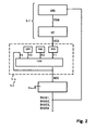
- FIG. 2 shows a block diagram of an embodiment of the inventive method for influencing the lateral dynamics of a vehicle, in particular the motor vehicle 1 according to Fig. 1 ,
- the method according to the invention begins with the determination of the transverse dynamics disturbance variable FSW in an observer block OBS on the basis of the vehicle dynamic actual variables of the vehicle measured by the sensors 6.1 to 6.n and on the basis of the brake force activation signals BKAS1-BKAS4.
- the method used in the observer block OBS to determine the transverse dynamics disturbance variable FSW is in the DE 10 2004 017 638 A1 described in this context.
- the transverse dynamic interference quantity FSW determined in this way by means of the observer block OBS is then high-pass filtered in a high-pass filter HP in order to filter out stationary portions of the transverse dynamics interference variable FSW, which are not to be taken into account in the following method. Only dynamic portions of the lateral dynamics disturbance variable FSW are considered in the further procedure.
- the high-pass filter HP generates the high-pass filtered transverse dynamics disturbance, which in the present case corresponds to the disturbance variable signal SGS, which is transmitted to the checking device 5.2 of the control unit 5.
- the intervention condition has a plurality of criteria which, according to the example, must be met individually in order to fulfill the engagement condition. These criteria serve to exclude driving situations in which no automatic braking intervention is to be caused.
- the intervention signal BES is determined in a logic block LOG, which is fed back as the fourth flag F4 to an input of the logic block LOG.
- the logic block both the values of the flags F1, F2, F3, F4 which are present in the current process cycle n and also the values of the flags F1, F2, F3, F4 from the preceding process cycle n-1 are used to determine the intervention signal BES.
- the values of the first flag F1, the second flag F2 and the fourth flag F4 from the previous method cycle are taken into account.
- Each row of the table corresponds to a combination of states that triggers or maintains a brake in the current cycle of the process: F2 (n-1) F2 (n) F1 (n-1) F1 (n) F3 (n) F4 (n-1) 0
- a new cycle begins analogous to the process cycle described above.
- the values F1, F2, F3, F4 for the preceding process cycle are respectively given a starting value F1 (start), F2 (start), F3 (start) and F4 (start), so that the method also can work on the first cycle, eg when starting the vehicle.
- start a starting value
- the exemplary embodiment described here carries out a braking intervention as a chassis intervention in order to counteract the transverse dynamics disturbance.
Abstract
Description
Die Erfindung betrifft ein Verfahren zum Beeinflussen der Querdynamik eines Fahrzeugs, insbesondere eines Kraftfahrzeugs, und eine Querdynamik-Beeinflussungsvorrichtung, wobei eine auf das Fahrzeug und insbesondere den Fahrzeugaufbau einwirkende Querdynamik-Störgröße mittels einer Störgrößen-Bestimmungseinrichtung bestimmt und ein Fahrwerkseingriff Bremseingriff hervorgerufen wird.The invention relates to a method for influencing the lateral dynamics of a vehicle, in particular of a motor vehicle, and a lateral dynamics influencing device, wherein a transverse dynamic interference variable acting on the vehicle and in particular the vehicle structure is determined by means of a disturbance variable determination device and a brake engagement is brought about.
Des Weiteren betrifft die vorliegende Erfindung eine Querdynamik-Beeinflussungsvorrichtung für ein Fahrzeug, insbesondere ein Kraftfahrzeug, mit einer Störgrößen-Bestimmungseinrichtung zum Bestimmen einer auf das Fahrzeug und insbesondere den Fahrzeugaufbau einwirkenden Querdynamik-Störgröße.Furthermore, the present invention relates to a lateral dynamics influencing device for a vehicle, in particular a motor vehicle, with a disturbance determination device for determining a transverse dynamic disturbance variable acting on the vehicle and in particular the vehicle body.
Zur Steigerung der Fahrsicherheit beim Führen eines Fahrzeugs, insbesondere eines Kraftfahrzeugs, ist es wünschenswert, den Fahrer bei plötzlich auftretenden Beeinflussungen oder Störungen der Fahrzeug-Querdynamik zu unterstützen. Derartige Störungen der Fahrzeug-Querdynamik können insbesondere bei starkem Seitenwind in Verbindung mit Seitenwindböen auftreten.To increase the driving safety when driving a vehicle, in particular a motor vehicle, it is desirable to assist the driver in case of sudden influences or disturbances of the vehicle lateral dynamics. Such disturbances of the vehicle lateral dynamics can occur in particular in strong crosswinds in conjunction with crosswinds.
Aus der
Weiterhin ist aus der
Aus der
Der Erfindung liegt die Aufgabe zu Grunde, ausgehend von einem Verfahren und einer Vorrichtung der jeweils eingangs genannten Art ein Verfahren beziehungsweise eine Vorrichtung anzugeben, so dass bei unterschiedlichen Fahrsituationen eine Erhöhung der Fahrsicherheit erreicht wird.The invention is based on the object, starting from a method and a device of the type mentioned in each case to specify a method or a device, so that an increase in driving safety is achieved in different driving situations.
Die Aufgabe wird bei einem Verfahren gemäß den Merkmalen des Patentanspruchs 1 gelöst und bei einer Querdynamik-Beeinflussungsvorrichtung gemäß den Merkmalen des Patentanspruchs 16 gelöst.The object is achieved in a method according to the features of
Der Fahrzeugführer muss erfindungsgemäß bei einer plötzlichen Störung der Fahrzeug-Querdynamik nicht mehr mit einer möglicherweise unkontrollierten Lenkbewegung reagieren, sondern es kommt zu einer automatischen Kompensation bzw. Korrektur der Störung, wodurch die Fahrsicherheit erhöht wird. Dies erfolgt zudem erfindungsgemäß, ohne von bestimmten externen Einrichtungen, wie der oben erwähnten Leitvorrichtung, abhängig zu sein. Zudem wird der Fahrwerkseingriff nur dann ausgelöst, wenn die Eingriffsbedingung erfüllt ist. Auf diese Weise werden Fahrsituationen, in denen ein Fahrwerkseingriff, insbesondere ein Bremseingriff, keine die Fahrsicherheit erhöhende Wirkung hätte ausgeschlossen. Fahrwerkseingriffe, die die Fahrsicherheit mindern könnten, werden nicht durchgeführt.The driver must not react according to the invention in a sudden disturbance of the vehicle lateral dynamics with a possibly uncontrolled steering movement, but it comes to an automatic compensation or correction of Disturbance, whereby the driving safety is increased. This is also done according to the invention, without depending on certain external devices, such as the above-mentioned guide device. In addition, the chassis intervention is only triggered when the intervention condition is met. In this way, driving situations in which a chassis intervention, in particular a braking intervention, would not have precluded driving safety. Chassis interventions that could reduce driving safety are not carried out.
Die Eingriffsbedingung ist erfüllt, wenn eines der angegebenen Kriterien oder eine Gruppe von mehreren der angegebenen Kriterien erfüllt ist:
- der Betrag der ermittelten Querdynamik-Störgröße ist größer als ein Störgrößenschwellenwert, wodurch Bremseingriffe bei geringen Querdynamikstörungen vermieden werden;
- die Fahrzeuglängsgeschwindigkeit ist größer als ein Fahrzeuglängsgeschwindigkeitsschwellenwert, wodurch Bremseingriffe in einer unkritischen Situationen mit kleiner Fahrzeuglängegeschwindigkeit vermieden werden kann;
- die sensorisch erfasste Istgierrate ist kleiner oder gleich einer beispielsweise anhand der Istquerbeschleunigung berechneten aktuellen Gierrate, um unnötige Bremseingriffe in Situationen zu vermeiden, bei denen die auftretende Gierrate bzw. Querbeschleunigung nicht hauptursächlich durch die Querdynamik-Störgröße hervorgerufen wurde;
- eine vom Fahrer durch Bremsen hervorgerufene, ein Bremsmoment beschreibende Bremsmomentgröße ist kleiner oder gleich einem Bremsmomentschwellenwert, so dass bei Bremsvorgängen mit großen Bremsmomenten, wie z.B. Not- bzw. Vollbremsvorgängen, automatische einseitige Bremseingriffe vermieden werden;
- eine den aktuellen Federweg an einer Fahrwerksfeder eines Fahrzeugrades beschreibende Federweggröße ist kleiner oder gleich einem Federwegschwellenwert;
- eine die Differenz der aktuellen Federwege an den beiden Fahrwerksfedern einer Fahrzeugachse beschreibende Differenzfederweggröße ist kleiner oder gleich einem Differenzfederwegschwellenwert;
- eine die Schlupfdifferenz zwischen zwei Fahrzeugrädern beschreibende Schlupfdifferenzgröße ist kleiner oder gleich einem Schlupfdifferenzschwellenwert.
- the amount of the determined transverse dynamics disturbance is greater than a Störgrößenschwellenwert, whereby braking interventions are avoided at low transverse dynamics disturbances;
- the vehicle longitudinal speed is greater than a vehicle longitudinal speed threshold, whereby brake interventions can be avoided in a non-critical situations with small vehicle length speed;
- the sensor-detected actual yaw rate is less than or equal to a current yaw rate calculated, for example, based on the actual lateral acceleration in order to avoid unnecessary brake interventions in situations in which the occurring yaw rate or lateral acceleration was not caused mainly by the transverse dynamics interference variable;
- a brake torque variable caused by the driver by braking and describing a braking torque is less than or equal to a braking torque threshold, so that automatic one-sided braking interventions are avoided during braking operations with large braking torques, such as emergency braking or full braking;
- a spring travel variable describing the current spring travel on a suspension spring of a vehicle wheel is less than or equal to a suspension travel threshold value;
- a Differenzfederweggröße describing the difference of the current spring travel on the two suspension springs of a vehicle axle is less than or equal to a Differenzfederwegschwellenwert;
- a slip difference amount describing the slip difference between two vehicle wheels is less than or equal to a slip difference threshold value.
Vorteilhafte Ausgestaltungen der Erfindung ergeben sich aus den abhängigen Patentansprüchen.Advantageous embodiments of the invention will become apparent from the dependent claims.
Vorteilhafterweise ist die Eingriffsbedingung nur dann erfüllt, wenn der Betrag des Lenkradwinkels kleiner oder gleich einem Lenkradwinkelschwellenwert ist und/oder wenn der Betrag der Lenkradwinkelgeschwindigkeit kleiner oder gleich einem Lenkradwinkelgeschwindigkeitsschwellenwert ist. Dadurch kann ein Fahrwerkseingriff bei dynamischen Lenkraddrehungen durch den Fahrer vermieden werden, um die Fahrsicherheit nicht zu gefährden.Advantageously, the engagement condition is satisfied only when the amount of the steering wheel angle is less than or equal to a steering wheel angle threshold and / or when the amount of steering wheel angular velocity is less than or equal to a steering wheel angular velocity threshold. As a result, a chassis intervention during dynamic steering wheel turns by the driver can be avoided so as not to jeopardize driving safety.
Des Weiteren kann die Eingriffsbedingung nur dann erfüllt sein, wenn der Betrag der stationären Querbeschleunigung kleiner oder gleich einem Querbeschleunigungsschwellenwert ist. Auf diese Weise werden Fahrwerkseingriffe beim Fahren von dynamischen Manövern, beispielsweise beim Durchfahren von Kurven mit entsprechend kleinen Kurvenradien vermieden. Es wird mithin eine längsgeschwindigkeitsabhängige Lenkradwinkelbegrenzung erreicht.Furthermore, the engagement condition can be satisfied only when the amount of the stationary lateral acceleration is less than or equal to a lateral acceleration threshold. In this way, chassis interventions when driving dynamic maneuvers, for example when driving through curves with correspondingly small curve radii, are avoided. It is thus achieved a longitudinal speed-dependent steering wheel angle limitation.
Es ist auch möglich, mittels der Störgrößen-Bestimmungseinrichtung einen auf den Fahrzeugaufbau des Fahrzeugs einwirkenden Seitenwind zu erkennen und durch den Fahrwerkseingriff eine entsprechende Störung der Querdynamik des Fahrzeugs zumindest teilweise zu kompensieren, um die Fahrsicherheit im Falle von auftretendem Seitenwind zu erhöhen.It is also possible to detect by means of the disturbance variable determination device acting on the vehicle body of the vehicle crosswind and compensate by the chassis intervention a corresponding disturbance of the lateral dynamics of the vehicle at least partially to increase the driving safety in the event of crosswinds occurring.
Der Fahrwerkseingriff kann ein
- Bremseingriff an einem oder mehreren Rädern sein und/oder
- eine Beeinflussung der Radaufstandskräfte an einem oder mehreren Rädern und/oder
- eine Beeinflussung des Servomoments eines Servomotors eines Servolenksystems und/oder
- eine Veränderung eines oder mehrerer Radantriebsmomente an einem oder mehreren Rädern sein.
- Be brake intervention on one or more wheels and / or
- an influence on the wheel contact forces on one or more wheels and / or
- an influence on the servo torque of a servomotor of a power steering system and / or
- a change of one or more wheel drive torques on one or more wheels.
Des Weiteren kann ein Eingriffsbestimmungswert ermittelt werden, der den Betrag der Querdynamik-Störgröße oder den Betrag des anhand der Querdynamik-Störgröße ermittelten, zur Kompensation der Querstörung einzustellenden Giermoments oder den Betrag einer sonstigen, mit einer der beiden Größen korrelierenden Größe beschreibt. Dabei kann bei Beträgen des Eingriffsbestimmungswerts unterhalb eines unteren Schwellenwertes nur eines der Räder, insbesondere eines der nicht lenkbaren Räder, über eine jeweils zugeordnete Bremseinrichtung abgebremst werden. Bei Beträgen des Eingriffsbestimmungswerts größer oder gleich dem unteren Schwellenwert und kleiner als ein oberer Schwellenwert, kann nur eines der lenkbaren Räder an der Vorderachse über die jeweils zugeordnete Bremseinrichtung abgebremst werden. Weiterhin können bei Beträgen des Eingriffsbestimmungswerts größer oder gleich dem oberen Schwellenwert beide Räder derselben Fahrzeugseite über die jeweils zugeordnete Bremseinrichtung abgebremst werden. Auf diese Weise kann der Bremseingriff angepasst an die Intensität der durch die Querdynamik-Störgröße verursachten Querdynamikstörung erfolgen.Furthermore, an intervention determination value can be determined which describes the magnitude of the transverse dynamics interference variable or the magnitude of the yawing moment determined with the aid of the transverse dynamics interference variable or the value of another variable correlating with one of the two variables in order to compensate for the cross interference. In the case of amounts of the intervention determination value below a lower threshold value, only one of the wheels, in particular one of the non-steerable wheels, can be braked via an respectively associated braking device. For amounts of engagement engagement value greater than or equal to the lower threshold and less than an upper threshold, only one of the steerable wheels on the front axle can be braked via the respective associated brake device. Furthermore, for amounts of the engagement determination value greater than or equal to the upper threshold value, both wheels of the same vehicle side can be braked via the respective associated brake device. In this way, the braking intervention can be adapted to the intensity of the transverse dynamics disturbance caused by the transverse dynamics disturbance variable.
Ferner besteht auch die Möglichkeit, beide Räder derselben Fahrzeugseite über die jeweils zugeordnete Bremseinrichtung abzubremsen, wobei die Bremskraftverteilung zwischen dem lenkbaren Rad und dem entsprechenden nicht lenkbaren Rad derselben Fahrzeugseite parameterabhängig ist und insbesondere fahrzeugabhängig vorgegeben und/oder fahrsituationsabhängig eingestellt werden kann.Furthermore, it is also possible to decelerate both wheels of the same vehicle side via the respective associated braking device, wherein the brake force distribution between the steerable wheel and the corresponding non-steerable wheel of the same vehicle side is parameter-dependent and in particular can be specified vehicle-dependent and / or dependent on the driving situation.
Im Folgenden wird ein Ausführungsbeispiel der Erfindung anhand der Zeichnung erläutert. Es zeigen:
- Fig. 1
- eine schematische Darstellung eines Kraftfahrzeugs mit einer Ausgestaltung der erfindungsgemäßen Vor- richtung,
- Fig. 2
- ein Blockschaltbild zur Darstellung eines Ablaufs einer Ausgestaltung des erfindungsgemäßen Verfah- rens,
- Fig. 3
- ein Blockschaltbild der Überprüfung mehrerer Krite- rien einer Eingriffsbedingung in einem Gültigkeits- block VAL aus
Fig. 2 und - Fig. 4
- ein Blockschaltbild der Überprüfung weiterer Krite- rien einer Eingriffsbedingung in einem Ausschalt- block OFF aus
Fig. 2 .
- Fig. 1
- a schematic representation of a motor vehicle with an embodiment of the device according to the invention,
- Fig. 2
- 1 is a block diagram to illustrate a sequence of an embodiment of the method according to the invention;
- Fig. 3
- a block diagram of the review of several criteria of an intervention condition in a validity block VAL
Fig. 2 and - Fig. 4
- a block diagram of the review of other criteria of an intervention condition in a turn-OFF OFF
Fig. 2 ,
Die Sensoren 6.1-6.n dienen zur Bestimmung von fahrdynamischen Istgrößen des Fahrzeugs 1, wie einer Istgierrate, einer Fahrzeuglängsgeschwindigkeit, eines Lenkradwinkels, eines Lenkwinkels oder einer Istquerbeschleunigung. Entsprechende Sensorsignale in SS1-SSn werden von den Sensoren 6.1-6.n an die Steuereinheit 5 und mithin an die Störgrößen-Bestimmungseinrichtung 5.1 und die Überprüfungseinrichtung 5.2 übermittelt.The sensors 6.1-6.n are used to determine actual driving dynamics of the
Die Störgrößen-Bestimmungseinrichtung 5.1 bestimmt aus den Istgrößen des Fahrzeugs 1 eine Querdynamik-Störgröße des Fahrzeugs wie dies in der deutschen Patentanmeldung
Die Störgrößen-Bestimmungseinrichtung 5.1 erzeugt ein Störgrößensignal SGS, welches an die Überprüfungseinrichtung 5.2 übermittelt wird. Bei der Überprüfung in der Überprüfungseinrichtung 5.2 wird anhand einer vorgegebenen Eingriffsbedingung festgestellt, ob ein Bremseingriff hervorgerufen werden soll, der der Querdynamikstörung entgegenwirkt. Ein entsprechendes Eingriffssignal BES wird zu der Bremskraft-Aktivierungseinrichtung 4 übertragen. Letztere aktiviert in Abhängigkeit von dem Eingriffssignal BES wenigstens eine oder mehrere der Bremseinheiten 3.1-3.4 mittels entsprechender Bremskraft-Aktivierungssignale BKAS1-BKAS4. Die Bremskraft-Aktivierungssignale BKAS1-BKAS4 werden auch der Steuereinheit 5 und insbesondere der Störgrößen-Bestimmungseinrichtung 5.1 übermittelt, um das an einer Fahrzeugseite verursachte Bremsmoment und die daraus resultierende Beeinflussung der Gierbewegung des Fahrzeugs bei der Bestimmung der Querdynamik-Störgröße berücksichtigen zu können.The disturbance variable determination device 5.1 generates an interference quantity signal SGS, which is transmitted to the checking device 5.2. When checking in the checking device 5.2 is determined based on a predetermined intervention condition, whether a braking intervention is to be caused, which counteracts the transverse dynamics disturbance. A corresponding engagement signal BES is transmitted to the brake
Grundsätzlich wird der Bremseingriff zumindest an einem Rad 2.1, 2.4 oder 2.2, 2.3einer Fahrzeugseite durchgeführt, um ein der Querstörung entgegen gerichtetes Giermoment zu erzeugen. Um den Bremseingriff für den Fahrer möglichst komfortabel zu gestalten kann ausschließlich oder zumindest in einer ersten Bremseingriffsstufe nur das entsprechende nicht lenkbare Rad 2.1 oder 2.2 an der Hinterachse des Fahrzeugs abgebremst werden, so dass eventuell spürbare Rückwirkungen am Lenkrad des Fahrzeugs 1 so gering wie möglich bleiben. Wie stark etwaige Rückwirkungen beim radindividuellen Bremsen eines lenkbaren Rades 2.3 oder 2.4 auf das Lenkrad sind, ist vom Fahrzeugtyp und dessen Fahrwerksauslegung abhängig. Ob der Bremseingriff an einem lenkbaren Rad 2.3 bzw. 2.4 und/oder an einem nicht lenkbaren Rad 2.1 bzw. 2.2 erfolgt, wird individuell an den Fahrzeugtyp angepasst. Bei Fahrzeugtypen, bei denen beim Bremsen eines lenkbaren Rades 2.3 oder 2.4 nur geringe Rückwirkungen am Lenkrad auftreten, kann daher alternativ oder zusätzlich zum nicht lenkbaren Hinterrad 2.1 oder 2.2 auch das lenkbare Rad 2.3 oder 2.4 derselben Fahrzeugseite zur Kompensation von Querstörungen abgebremst werden.In principle, the braking intervention is performed on at least one wheel 2.1, 2.4 or 2.2, 2.3 of a vehicle side, in order to generate a yawing moment directed against the transverse disturbance. In order to make the braking operation as comfortable as possible for the driver, only the corresponding non-steerable wheel 2.1 or 2.2 at the rear axle of the vehicle can be braked exclusively or at least in a first braking engagement stage, so that any noticeable repercussions on the steering wheel of the
Es ist daher möglich, den Bremseingriff so zu gestalten, dass die Räder 2.1, 2.4 oder 2.2, 2.3 einer Fahrzeugseite gleichzeitig abgebremst werden. Die Bremskraftverteilung zwischen lenkbarem Vorderrad 2.3 oder 2.4 und Hinterrad 2.2 oder 2.1 auf dieser Fahrzeugseite kann fahrzeugabhängig vorgegeben und/oder fahrsituationsabhängig eingestellt werden. Zum Beispiel kann die Bremskraftverteilung zwischen lenkbarem Vorderrad 2.3 oder 2.4 und nicht lenkbarem Hinterrad 2.2 oder 2.1 von Parametern wie dem Betrag der Querdynamik-Störgröße, dem Lenkwinkel, der Längsgeschwindigkeit, der Querbeschleunigung, der Gierrate oder anderen längs- und querdynamischen Fahrzustandsgrößen abhängen.It is therefore possible to make the braking intervention so that the wheels are braked 2.1, 2.4 or 2.2, 2.3 a vehicle side simultaneously. The braking force distribution between steerable front wheel 2.3 or 2.4 and rear wheel 2.2 or 2.1 on this side of the vehicle can be specified depending on the vehicle and / or adjusted depending on the driving situation. For example, the braking force distribution between steerable front wheel 2.3 or 2.4 and non-steerable rear wheel 2.2 or 2.1 may depend on parameters such as the amount of lateral dynamics disturbance, steering angle, longitudinal velocity, lateral acceleration, yaw rate, or other longitudinal and lateral dynamic driving state quantities.
In der Überprüfungseinrichtung 5.2 kann ein Eingriffsbestimmungswert bestimmt werden, der den Betrag der Querdynamik-Störgröße oder den Betrag des anhand der Querdynamik-Störgröße ermittelten, zur Kompensation der Querstörung einzustellenden Giermoments oder den Betrag einer sonstigen, mit einer der beiden Größen korrelierenden Größe beschreibt. Abhängig vom Eingriffsbestimmungswert kann dann ein mehrstufiger Bremseingriff erfolgen, wobei sich z.B. folgende Möglichkeiten ergeben:
- a) Der Eingriffsbestimmungswert überschreitet den Eingriffsschwellenwert und ist kleiner als ein vorgegebener unterer Schwellenwert: Zunächst wird nur ein Rad 2.1 oder 2.2 oder 2.3 oder 2.4, vorzugsweise ein nicht lenkbares Rad 2.3 oder 2.4 abgebremst. Erst wenn dieser ausschließlich an einem der Räder 2.1 oder 2.2 oder 2.3 oder 2.4 durchgeführte Bremseingriff keine ausreichende Wirkung zeigt, wird zusätzlich das weitere Rad 2.1 oder 2.2 oder 2.3 oder 2.4 derselben Fahrzeugseite abgebremst.
- b) Wenn der Eingriffsbestimmungswert größer ist als oder gleich groß wie der vorgegebene untere Schwellenwert werden sofort beide Räder 2.1, 2.4 oder 2.2, 2.3 derselben Fahrzeugseite abgebremst, um einen ausreichend schnelle Kompensation bzw. Reduzierung der Querdynamikbeeinflussung des Fahrzeugs 1 durch die Querdynamik-Störgröße sicherzustellen und eine hohe Fahrsicherheit zu gewährleisten.
- c) In einer weiteren Ausprägung ist es auch möglich, drei Eingriffsstufen vorzusehen:
- Bei einem Eingriffsbestimmungswert oberhalb des Eingriffsschwellenwerts und unterhalb des unteren Schwellenwertes wird nur eines der nicht lenkbaren Räder 2.1 oder 2.2 über die jeweils zugeordnete Bremseinrichtung 3.1 bzw. 3.2 abgebremst.
- Bei einem Eingriffsbestimmungswert größer oder gleich dem unteren Schwellenwert und kleiner einem oberen Schwellenwert wird nur eines der lenkbaren Räder 2.3 oder 2.4 an der Vorderachse über die jeweils zugeordnete Bremseinrichtung 3.3 bzw. 3.4 abgebremst.
- Bei einem Eingriffsbestimmungswert größer oder gleich dem oberen Schwellenwert werden beide Räder 2.1, 2.4 oder 2.2, 2.3 derselben Fahrzeugseite durch die jeweils zugeordnete Bremseinrichtungen 3.1, 3.4 oder 3.2, 3.3 abgebremst.
- a) The engagement determination value exceeds the engagement threshold and is smaller than a predetermined lower threshold: First, only one wheel 2.1 or 2.2 or 2.3 or 2.4, preferably a non-steerable wheel 2.3 or 2.4 braked. Only when this exclusively on one of the wheels 2.1 or 2.2 or 2.3 or 2.4 performed braking intervention does not have sufficient effect, in addition, the other wheel is braked 2.1 or 2.2 or 2.3 or 2.4 same side of the vehicle.
- b) If the engagement determination value is greater than or equal to the predetermined lower threshold immediately both wheels are braked 2.1, 2.4 or 2.2, 2.3 the same vehicle side to ensure a sufficiently rapid compensation or reduction of the lateral dynamics influence of the
vehicle 1 by the transverse dynamics disturbance and to ensure a high driving safety. - c) In another form, it is also possible to provide three intervention levels:
- At an engagement determination value above the engagement threshold and below the lower threshold, only one of the non-steerable wheels becomes 2.1 or 2.2 braked via the respectively associated braking device 3.1 or 3.2.
- With an intervention determination value greater than or equal to the lower threshold value and less than an upper threshold value, only one of the steerable wheels 2.3 or 2.4 on the front axle is braked via the respective associated brake device 3.3 or 3.4.
- With an intervention determination value greater than or equal to the upper threshold value, both wheels 2.1, 2.4 or 2.2, 2.3 of the same vehicle side are braked by the respective associated brake devices 3.1, 3.4 or 3.2, 3.3.
Wirkt auf den Fahrzeugaufbau des Fahrzeugs 1 z.B. eine Seitenwindböe SW in Fahrtrichtung gesehen von rechts ein, so kann das rechte hintere Rad 2.2 und/oder das rechte vordere Rad 2.3 abgebremst werden, um dadurch ein Giermoment auf das Fahrzeug 1 um seine Hochachse im Uhrzeigersinn zu generieren. Bei einem von links auf das Fahrzeug 1 einwirkenden Seitenwind sind die Richtungen genau umgekehrt, wobei dann das linke vordere Rad 2.4 und/oder das linke hintere Rad 2.1 abgebremst werden.Acts on the vehicle body of the
Durch den Bremseingriff wird erfindungsgemäß die Störung der Querdynamik durch den Seitenwind SW zumindest teilweise kompensiert. Zu diesem Zweck ist die Störgrößen-Bestimmungseinrichtung 5 und/oder die Bremskraft-Aktivierungseinrichtung 4 dazu ausgebildet, mittels eines geeigneten Verfahrens beziehungsweise Modells, eine erforderliche Bremskraft an einem Rad oder mehreren Rädern 2.1-2.4 des Fahrzeugs 1 zu ermitteln, um entsprechend - wie bereits erwähnt - die aufgetretene Störung der Fahrzeug-Querdynamik zu kompensieren.Due to the braking intervention, according to the invention the disturbance of the lateral dynamics by the side wind SW is at least partially compensated. For this purpose, the
Der Führer des Fahrzeugs 1 wird also bei der Kompensation einer Störung der Fahrzeug-Querdynamik, wie beispielsweise durch eine Seitenwindböe, unterstützt. Die auftretende Störung der Querdynamik wird automatisch vermindert oder vollständig kompensiert. Dies trägt zu einer Erhöhung der Fahrsicherheit bei.The driver of the
Nachfolgend wird ein Ausführungsbeispiel eines Verfahrens anhand von
Das erfindungsgemäße Verfahren beginnt mit der Bestimmung der Querdynamik-Störgröße FSW in einem Beobachterblock OBS auf Basis der mittels der Sensoren 6.1 bis 6.n gemessenen fahrdynamischen Istgrößen des Fahrzeugs und auf Basis der Bremskraft-Aktivierungssignale BKAS1-BKAS4. Das im Beobachterblock OBS verwendete Verfahren zur Bestimmung der Querdynamik-Störgröße FSW ist in der
Die auf diese Weise mittels des Beobachterblocks OBS ermittelte Querdynamik-Störgröße FSW wird anschließend in einem Hochpassfilter HP hochpassgefiltert, um stationäre Anteile der Querdynamik-Störgröße FSW herauszufiltern, die im Folgenden Verfahren nicht berücksichtigt werden sollen. Lediglich dynamische Anteile der Querdynamik-Störgröße FSW werden im weiteren Verfahren berücksichtigt. Der Hochpassfilter HP erzeugt die hochpassgefilterte Querdynamik-Störgröße, die im vorliegenden Fall dem Störgrößensignal SGS entspricht, das an die Überprüfungseinrichtung 5.2 der Steuereinheit 5 übermittelt wird.The transverse dynamic interference quantity FSW determined in this way by means of the observer block OBS is then high-pass filtered in a high-pass filter HP in order to filter out stationary portions of the transverse dynamics interference variable FSW, which are not to be taken into account in the following method. Only dynamic portions of the lateral dynamics disturbance variable FSW are considered in the further procedure. The high-pass filter HP generates the high-pass filtered transverse dynamics disturbance, which in the present case corresponds to the disturbance variable signal SGS, which is transmitted to the checking device 5.2 of the
In der Überprüfungseinrichtung 5.2 wird überprüft, ob eine vorgegebene Eingriffsbedingung erfüllt ist. Die Eingriffsbedingung weist beim Ausführungsbeispiel des Verfahrens mehrere Kriterien auf, die beispielsgemäß jeweils einzeln erfüllt sein müssen, um die Eingriffsbedingung zu erfüllen. Diese Kriterien dienen dazu, Fahrsituationen auszuschließen, in denen kein automatischer Bremseingriff hervorgerufen werden soll.In the checking device 5.2 is checked whether a predetermined intervention condition is met. In the exemplary embodiment of the method, the intervention condition has a plurality of criteria which, according to the example, must be met individually in order to fulfill the engagement condition. These criteria serve to exclude driving situations in which no automatic braking intervention is to be caused.
In einem Hystereseblock HYS wird als erstes Kriterium geprüft, ob das Störgrößensignal SGS - also die hochpassgefilterte Querdynamik-Störgröße - größer ist als ein vorgegebener Aktivierungsschwellenwert oder kleiner als ein Deaktivierungsschwellenwert. Der Aktivierungsschwellenwert ist größer als der Deaktivierungsschwellenwert, so dass eine Hysterese gebildet ist. Ist das Störgrößensignal SGS größer als der Aktivierungsschwellenwert, so wird ein erstes Flag F1=1 gesetzt. Ist das Störgrößensignal SGS hingegen kleiner als der Deaktivierungsschwellenwert, so wird das erste Flag K1=0 gesetzt:
- SGS > Aktivierungsschwellenwert ⇒ F1=1 oder
- SGS < Deaktivierungsschwellenwert ⇒ F1=0.
- SGS> Activation Threshold ⇒ F1 = 1 or
- SGS <deactivation threshold ⇒ F1 = 0.
In einem Gültigkeitsblock VAL werden weitere Kriterien überprüft, beispielsgemäß acht Kriterien K2 bis K9, über die die aktuelle Fahrsituation beurteilt wird, wie dies in
- zweites Kriterium K2:
- es wird geprüft, ob der Betrag des Lenkradwinkels δ kleiner oder gleich einem Lenkradwinkelschwellenwert δs ist;
- drittes Kriterium K3:
- es wird geprüft, ob der Betrag der Lenkradwinkelgeschwindigkeit δ̇ kleiner oder gleich einem Lenkradwinkelgeschwindigkeitsschwellenwert δ̇s ist;
- viertes Kriterium K4:
- es wird geprüft, ob die Fahrzeuglängsgeschwindigkeit vx größer ist als ein Fahrzeuglängsgeschwindigkeitsschwellenwert vxs;
- fünftes Kriterium K5:
- es wird geprüft, ob die sensorisch erfasste Istgierrate Ψ̇ kleiner oder gleich einer berechneten aktuellen Gierrate Ψ̇ Mod ist; die berechnete aktuelle Gierrate Ψ̇ Mod wird auf Basis eines vorgegebenen Fahrzeugmodells, das den Zusammenhang zwischen Querbeschleunigung und Gierrate beschreibt, anhand der gemessenen Istquerbeschleunigung ay bestimmt;
- sechstes Kriterium K6:
- es wird geprüft, ob der Betrag der stationären Querbeschleunigung ay,stat kleiner oder gleich einem Querbeschleunigungsschwellenwert ay,stat,s ist;
- siebtes Kriterium K7:
- es wird geprüft, ob eine vom Fahrer durch Bremsen hervorgerufenes Bremsmoment Mbr, das beim Ausführungsbeispiel eine Bremsmomentgröße darstellt,
- kleiner oder gleich einem Bremsmomentschwellenwert Mbrs ist;
- achtes Kriterium K8:
- es wird geprüft, ob die aktuellen Federwege zVL, zVR, zHL, zHR an den Fahrwerksfedern der Fahrzeugrädern 2.1 (HL), 2.2 (HR), 2.3 (VR), 2.4 (VL), die beispielsgemäß eine Federweggröße darstellt, kleiner oder gleich einem Federwegschwellenwert zs sind; zusätzlich wird geprüft, ob der Betrag einer Differenzfederweggröße ,
- die beispielsgemäß von der Differenz |zHPVL -zHPVR | der insbesondere über einen Hochpass hochpassgefilterten aktuellen Federwege zHPVL, zHPVR an den beiden Fahrwerksfedern einer Fahrzeugachse gebildet ist, kleiner oder gleich einem Differenzfederwegschwellenwert Δzs ist;
- neuntes Kriterium K9:
- es wird geprüft, ob eine Schlupfdifferenzgröße, die hier von der Schlupfdifferenz zwischen zwei Fahrzeugrädern gebildet ist, kleiner oder gleich einem Schlupfdifferenzschwellenwert ist; beispielsgemäß wird eine erste Schlupfdifferenz |λ VL -λ VR | zwischen den beiden Vorderrädern 2.3 (VR), 2.4 (VL) und eine zweite Schlupfdifferenz |λ IIL -λ IIR | zwischen den beiden Hinterrädern 2.1 (HL), 2.2 (HR) mit einem Vorderachs-Schlupfdifferenzschwellenwert λvs bzw. einem Hinterachs-Schlupfdifferenzschwellenwert λvs verglichen:


- es wird geprüft, ob eine Schlupfdifferenzgröße, die hier von der Schlupfdifferenz zwischen zwei Fahrzeugrädern gebildet ist, kleiner oder gleich einem Schlupfdifferenzschwellenwert ist; beispielsgemäß wird eine erste Schlupfdifferenz |λ VL -λ VR | zwischen den beiden Vorderrädern 2.3 (VR), 2.4 (VL) und eine zweite Schlupfdifferenz |λ IIL -λ IIR | zwischen den beiden Hinterrädern 2.1 (HL), 2.2 (HR) mit einem Vorderachs-Schlupfdifferenzschwellenwert λvs bzw. einem Hinterachs-Schlupfdifferenzschwellenwert λvs verglichen:
- second criterion K2:
- It is checked whether the amount of the steering wheel angle δ is less than or equal to a steering wheel angle threshold δ s ;
- third criterion K3:
- it is checked whether the amount of the steering wheel angular velocity δ̇ is less than or equal to a steering wheel angular velocity threshold δ̇ s ;
- fourth criterion K4:
- it is checked whether the vehicle longitudinal speed v x is greater than a vehicle longitudinal speed threshold v xs ;
- fifth criterion K5:
- It is checked whether the sensed Istgierrate Ψ̇ is less than or equal to a calculated current yaw rate Ψ̇ Mod ; the calculated current yaw rate Ψ̇ Mod is determined on the basis of a given vehicle model, which describes the relationship between lateral acceleration and yaw rate, on the basis of the measured actual lateral acceleration ay;
- sixth criterion K6:
- it is checked whether the absolute value of the stationary lateral acceleration a y , stat is less than or equal to a lateral acceleration threshold value a y , stat , s ;
- seventh criterion K7:
- it is checked whether a braking torque M br caused by the driver by braking, which in the exemplary embodiment represents a braking torque variable,
- is less than or equal to a braking torque threshold M brs ;
- Eighth criterion K8:
- it is checked whether the current travel paths z VL , z VR , z HL , z HR on the suspension springs of the vehicle wheels 2.1 (HL), 2.2 (HR), 2.3 (VR), 2.4 (VL), which represents a spring travel, for example, are less than or equal to a spring travel threshold z s ; in addition, it is checked whether the amount of a differential spring travel size,
- the example of the difference | zHP VL - zHP VR | which is formed in particular via a high-pass high-pass filtered current spring travel zHP VL , zHP VR on the two suspension springs of a vehicle axle, is less than or equal to a Differenzfederwegschwanzwert Δz s ;
- Ninth criterion K9:
- It is checked whether a slip difference amount, which is here formed by the slip difference between two vehicle wheels, is less than or equal to a slip difference threshold value; For example, a first slip difference | λ VL -λ VR | between the two front wheels 2.3 (VR), 2.4 (VL) and a second slip difference | λ IIL -λ IIR | between the two rear wheels 2.1 (HL), 2.2 (HR) is compared with a front axle slip differential threshold value λ vs and a rear axle slip differential threshold value λ vs :
- It is checked whether a slip difference amount, which is here formed by the slip difference between two vehicle wheels, is less than or equal to a slip difference threshold value; For example, a first slip difference | λ VL -λ VR | between the two front wheels 2.3 (VR), 2.4 (VL) and a second slip difference | λ IIL -λ IIR | between the two rear wheels 2.1 (HL), 2.2 (HR) is compared with a front axle slip differential threshold value λ vs and a rear axle slip differential threshold value λ vs :
Über den Und-Verknüpfungsblock AND wird festgestellt, ob alle der acht Kriterien K2 bis K9 erfüllt sind, also ob alle in
In einem in
- erstes Ausschaltkriterium K10:
- es wird geprüft, ob der Betrag des Lenkradwinkels δ größer ist als der Lenkradwinkelschwellenwert δs;
- zweites Ausschaltkriterium K11:
- es wird geprüft, ob der Betrag der Lenkradwinkelgeschwindigkeit δ̇ größer ist als der Lenkradwinkelgeschwindigkeitsschwellenwert δ̇s;
- drittes Ausschaltkriterium K12:
- es wird geprüft, ob das vom Fahrer durch Bremsen hervorgerufenes Bremsmoment Mbr, größer ist als der Bremsmomentschwellenwert Mbrs.
- first switch-off criterion K10:
- It is checked whether the amount of the steering wheel angle δ is greater than the steering wheel angle threshold δ s ;
- second switch-off criterion K11:
- it is checked whether the amount of the steering wheel angular velocity δ̇ is greater than the steering wheel angular velocity threshold δ̇ s ;
- third switch-off criterion K12:
- It is checked whether the braking torque M br caused by the driver caused by braking is greater than the braking torque threshold value M brs .
Ist keines der Ausschaltkriterien K10, K11, K12 erfüllt, so ist das dritte Flag F3=0. Die Ausschaltkriterien K10, K11, K12 werden im Oder-Verknüpfungsblock OR miteinander zum dritten Flag F3 verknüpft.If none of the switch-off criteria K10, K11, K12 is fulfilled, then the third flag F3 = 0. The switch-off criteria K10, K11, K12 are linked together in the OR block OR to the third flag F3.
Unter Berücksichtigung der drei Flags F1, F2, F3 und eines vierten Flags F4 wird in einem Logikblock LOG das Eingriffssignal BES ermittelt, das als viertes Flag F4 an einen Eingang des Logikblocks LOG zurückgekoppelt wird. Im Logikblock werden zur Ermittlung des Eingriffssignals BES sowohl die im aktuellen Verfahrenszyklus n vorliegenden Werte der Flags F1, F2, F3, F4, als auch zum Teil die Werte der Flags F1, F2, F3, F4 aus dem vorangegangenen Verfahrenszyklus n-1 verwendet. Im vorliegenden Fall werden die Werte des ersten Flags F1, des zweiten Flags F2 und des vierten Flags F4 aus dem vorangegangenen Verfahrenszyklus berücksichtigt.Taking into account the three flags F1, F2, F3 and a fourth flag F4, the intervention signal BES is determined in a logic block LOG, which is fed back as the fourth flag F4 to an input of the logic block LOG. In the logic block both the values of the flags F1, F2, F3, F4 which are present in the current process cycle n and also the values of the flags F1, F2, F3, F4 from the preceding process cycle n-1 are used to determine the intervention signal BES. In the present case, the values of the first flag F1, the second flag F2 and the fourth flag F4 from the previous method cycle are taken into account.
Als notwendige Bedingungen für ein einen Bremsvorgang auslösendes Eingriffssignal BES gelten:
- das dritte Flag F3=0, d.h. keines der Ausschaltkriterien K10, K11, K12 ist erfüllt und
- das erste Flag F1=1, d.h. die im Hystereseblock HYS definierte Bedingungen müssen erfüllt sein.
- the third flag F3 = 0, ie none of the switch-off criteria K10, K11, K12 is fulfilled and
- the first flag F1 = 1, ie the conditions defined in the hysteresis block HYS must be fulfilled.
Das Eingriffssignal BES ist im aktuellen Verfahrenzyklus n BES(n)=F4(n)=1, wenn eine der in der folgenden Tabelle auftretenden Kombinationen auftritt. Jede Zeile der Tabelle entspricht einer Kombination von Zuständen, die im aktuellen Verfahrenszyklus einen Bremsvorgang auslöst oder aufrechterhält:
über die Bremskraft-Aktivierungseinrichtung 4 wird ein Bremsvorgang an einem oder mehreren der Räder ausgelöst oder aufrechterhalten, wenn das Eingriffssignal BES=1 ist. Anschließend beginnt ein neuer Verfahrenszyklus analog zu dem oben beschriebenen Verfahrenszyklus. Zu Beginn des ersten Verfahrenszyklus werden als Werte der Flags F1, F2, F3, F4 für den vorangegangenen Verfahrenszyklus jeweils ein Startwerte F1(Start), F2(Start), F3(Start) und F4(Start) vorgegeben, so dass das Verfahren auch beim ersten Verfahrenszyklus arbeiten kann, z.B. beim Starten des Fahrzeugs. Eine solche Vorgehensweise ist bei zyklischen Verfahren bekannt. Beispielsweise können die Startwerte wie folgt vorgegeben sein: F1(Start)=0, F2(Start)=0, F3(Start)=0 und F4(Start)=0.A brake operation on one or more of the wheels is triggered or maintained via the brake
Das hier beschriebene Ausführungsbeispiel führt als Fahrwerkseingriff einen Bremseingriff durch um der Querdynamik-Störung entgegenzuwirken.The exemplary embodiment described here carries out a braking intervention as a chassis intervention in order to counteract the transverse dynamics disturbance.
Alternativ oder zusätzlich kann die zumindest teilweise Kompensation der Querdynamik-Störung auch durch andere Fahrwerkseingriffe erfolgen:
- Das Servomoment eines Servomotors eines insbesondere elektrischen Servolenksystems kann beeinflusst werden, so dass der Fahrer beim Gegenlenken unterstützt wird. Das Servomoment ist so gerichtet, dass der Fahrer dazu veranlasst wird, der Querdynamik-Störung entgegenzulenken. Hält der Fahrer das Lenkrad nicht fest und gibt er dem Servomoment des Servomotors nach, erfolgt sozusagen ein automatisches Gegenlenken.
- Die Radaufstandkraft eines oder mehrerer Räder 2.1 - 2.4 des
Fahrzeugs 1 können verändert werden, beispielsweise durch die Ansteuerung eines dem betreffenden Rad 2.1, 2.2, 2.3, 2.4 zugeordneten aktiven Feder oder Dämpfersystems oder eines aktiven Stabilisators des Fahrzeugs. Beispielsweise kann die Radaufstandskraft zwei diagonal einender gegenüberliegenden Rädern 2.1 (HL) und 2.3 (VR) oder 2.2 (HR) und 2.4 (VL) gegenüber den beiden anderen Rädern 2.2 (HR) und 2.4 (VL) oder 2.1 (HL) und 2.3 (VR) erhöht werden. Durch die Achsgeometrie, insbesondere die Vorspur, wird eine Querkraft erzeugt. Alternativ oder zusätzlich können die Radaufstandskräfte auch an zwei sich diagonal gegenüberliegenden Rädern verringert werden. Diese Querkraft kann dazu verwendet werden, um die Querdynamik-Störung zumindest teilweise zu kompensieren. - Analog zur Durchführung eines Bremsvorgangs besteht auch die Möglichkeit, die Radantriebskraft ungleich auf die beiden Fahrzeugseiten zu verteilen, was beispielsweise über ein ansteuerbares Achsdifferenzial erreicht werden kann. Die Radantriebskraft kann also an einer Fahrzeugseite erhöht und/oder an der jeweils anderen Fahrzeugseite verringert werden. Aufgrund der ungleichen Radantriebskräfte auf beiden Fahrzeugseiten wird eine Gierbewegung hervorgerufen. Diese Gierbewegung erfolgt entgegen der Querdynamik-Störung und kann diese daher zumindest mindern und im Idealfall vollständig kompensieren.
- The servo torque of a servo motor of a particular electric power steering system can be influenced so that the driver is assisted in countersteering. The servo torque is directed to cause the driver to counter-steer the cross-dynamics fault. If the driver does not hold the steering wheel and gives in to the servomotor's servo torque, automatic countersteering takes place, so to speak.
- The wheel contact force of one or more wheels 2.1 - 2.4 of the
vehicle 1 can be changed, for example, by the activation of the relevant wheel 2.1, 2.2, 2.3, 2.4 associated active spring or damper system or an active stabilizer of the vehicle. For example, the wheel contact force may be two diagonally opposite wheels 2.1 (HL) and 2.3 (VR) or 2.2 (HR) and 2.4 (VL) opposite the other two wheels 2.2 (HR) and 2.4 (VL) or 2.1 (HL) and 2.3 (FIG. VR). Due to the axle geometry, in particular the toe, a lateral force is generated. Alternatively or additionally, the wheel contact forces can also be reduced at two diagonally opposite wheels. This lateral force can be used to at least partially compensate for the lateral dynamics perturbation. - Analogous to carrying out a braking operation, it is also possible to disperse the wheel drive power unequally on the two sides of the vehicle, which can be achieved, for example, via a controllable axle differential. The wheel drive force can thus be increased on one side of the vehicle and / or reduced on the other side of the vehicle. Due to the unequal wheel drive forces on both sides of the vehicle a yawing motion is caused. This yawing movement takes place counter to the transverse dynamic disturbance and can therefore at least reduce it and ideally completely compensate it.
Claims (16)
- Method for influencing the transversal dynamics of a vehicle (1), wherein a transversal dynamics disturbance variable acting on the vehicle (1) and in particular on the vehicle body is determined and wherein it is checked whether a preset intervention condition is fulfilled, wherein, if the intervention condition is fulfilled, a chassis intervention is performed to influence the transversal dynamics, and wherein the intervention condition is fulfilled if the amount of the determined disturbance variable exceeds a disturbance variable threshold value,
characterised in that
the intervention condition is fulfilled if in addition one of the following criteria or a group of several of the following criteria is met:- the longitudinal speed of the vehicle is higher than a longitudinal speed threshold value for the vehicle;- the actual yaw velocity detected by sensors is lower than or equal to a calculated current yaw velocity;- a slip differential variable defining the slip differential between two vehicle wheels is lower than or equal to a slip differential threshold value. - Method according to claim 1,
characterised in that
the intervention condition is fulfilled if a braking torque variable caused by the driver by braking and defining a braking torque is lower than or equal to a braking torque threshold value. - Method according to claim 1 or 2,
characterised in that
the intervention condition is fulfilled if at least one of the following criteria is met:- a spring deflection variable defining the current spring deflection of a chassis spring of a vehicle wheel is less than or equal to a spring deflection threshold value;- a differential spring deflection variable defining the difference between the current spring deflections at the two chassis springs of a vehicle axle is less than or equal to a differential spring deflection threshold value. - Method according to any of the preceding claims,
characterised in that
the intervention condition is fulfilled if the amount of the steering wheel angle is less than or equal to a steering wheel angle threshold value and/or if the amount of the angular steering wheel speed is less than or equal to an angular steering wheel speed threshold value. - Method according to any of the preceding claims,
characterised in that
the intervention condition is fulfilled if the amount of the stationary transverse acceleration is less than or equal to a transverse acceleration threshold value. - Method according to any of the preceding claims,
characterised in that
a side wind (SW) acting on the body of the vehicle (1) is determined by means of the disturbance variable determination device (5), and in that a corresponding disturbance of the transversal dynamics of the vehicle (1) is at least partially compensated for by the chassis intervention. - Method according to any of the preceding claims,
characterised in that
an intervention defining value is determined which defines the amount of the transversal dynamics disturbance variable or the amount of the yawing moment determined by means of the transversal dynamics disturbance variable and to be set to compensate for the transversal disturbance or the amount of another variable correlating with one of these two variables. - Method according to any of the preceding claims,
characterised in that
as a chassis intervention- a braking intervention is performed on one or more of the wheels (2.1 - 2.4) and/or- the wheel contact forces are influenced on one or more of the wheels (2.1 - 2.4) and/or- the servo torque of a servo motor of a power-assisted steering system is influenced and/or- one or more wheel drive torques is/are changed at on one or more of the wheels (2.1 - 2.4). - Method according to claim 8 in combination with claim 7,
characterised in that
at amounts of the intervention determination value below a lower threshold value, only one of the wheels (2.1 - 2.4), in particular one of the non-steered wheels (2.1 or 2.2), is braked by means of the assigned braking device (3.1 - 3.4). - Method according to claim 8 or 9 in combination with claim 7,
characterised in that
at amounts of the intervention determination value higher than or equal to the lower threshold value and lower than an upper threshold value, only one of the steered wheels (2.3 or 2.4) on the front axle is braked by means of the assigned braking device (3.3 or 3.4). - Method according to any of claims 9 to 10 in combination with claim 7,
characterised in that
at amounts of the intervention determination value higher than or equal to the upper threshold value, both wheels (2.1, 2.4 or 2.2, 2.3) of the same side of the vehicle are braked by means of the assigned braking device (3.1, 3.4 or 3.2, 3.3). - Method according to claim 8 in combination with claim 7,
characterised in that
both wheels (2.1, 2.4 or 2.2, 2.3) of the same side of the vehicle are braked by means of the assigned braking device (3.1, 3.4 or 3.2, 3.3), wherein the braking force is distributed between the steered wheel (2.3 or 2.4) and the corresponding non-steered wheel (2.2 or 2.1) on the same side of the vehicle in dependence on parameters and can in particular be preset in a vehicle-dependent manner and/or adjusted in dependence on driving situation. - Method according to any of the preceding claims,
characterised in that
a chassis intervention triggered by a fulfilment of the intervention conditions is terminated,- if the braking torque variable caused by the driver by braking and defining the braking torque is higher than the braking torque threshold value and/or- if the amount of the steering wheel angle is higher than a steering wheel angle threshold value and/or- if the amount of the angular steering wheel speed is higher than an angular steering wheel speed threshold value. - Method according to any of the preceding claims,
characterised in that
the transversal dynamics disturbance variable is filtered by means of a high-pass filter prior to the checking of the intervention condition. - Device for influencing the transversal dynamics of a vehicle (1), comprising a disturbance variable determination device (5.1) for the determination of a transversal dynamics disturbance variable acting on the vehicle (1) and in particular on the body of the vehicle, and a checking device (5.2) for checking whether a preset intervention condition is fulfilled, wherein, if the intervention condition is fulfilled, a chassis intervention is performed to influence the transversal dynamics, and wherein the intervention condition is fulfilled if the amount of the determined disturbance variable exceeds a disturbance variable threshold value,
characterised in that
the intervention condition is fulfilled if in addition one of the following criteria or a group of several of the following criteria is met:- the longitudinal speed of the vehicle is higher than a longitudinal speed threshold value for the vehicle;- the actual yaw velocity detected by sensors is lower than or equal to a calculated current yaw velocity;- a slip differential variable defining the slip differential between two vehicle wheels is lower than or equal to a slip differential threshold value. - Device for influencing the transversal dynamics of a vehicle (1) according to claim 15, characterised in that
the intervention condition is fulfilled if in addition one of the following criteria or a group of several of the following criteria is met:- a braking torque variable caused by the driver by braking and defining a braking torque is lower than or equal to a braking torque threshold value;- a spring deflection variable defining the current spring deflection of a chassis spring of a vehicle wheel is less than or equal to a spring deflection threshold value;- a differential spring deflection variable defining the difference between the current spring deflections at the two chassis springs of a vehicle axle is less than or equal to a differential spring deflection threshold value.
Applications Claiming Priority (2)
| Application Number | Priority Date | Filing Date | Title |
|---|---|---|---|
| DE102007029605A DE102007029605A1 (en) | 2007-06-27 | 2007-06-27 | Method and device for influencing the lateral dynamics of a vehicle |
| PCT/EP2008/004458 WO2009000388A2 (en) | 2007-06-27 | 2008-06-04 | Method and device for influencing the transversal dynamics of a vehicle |
Publications (2)
| Publication Number | Publication Date |
|---|---|
| EP2162811A2 EP2162811A2 (en) | 2010-03-17 |
| EP2162811B1 true EP2162811B1 (en) | 2011-02-23 |
Family
ID=40040133
Family Applications (1)
| Application Number | Title | Priority Date | Filing Date |
|---|---|---|---|
| EP08759014A Not-in-force EP2162811B1 (en) | 2007-06-27 | 2008-06-04 | Method and device for influencing the transversal dynamics of a vehicle |
Country Status (6)
| Country | Link |
|---|---|
| US (1) | US8930061B2 (en) |
| EP (1) | EP2162811B1 (en) |
| JP (1) | JP5247800B2 (en) |
| AT (1) | ATE499643T1 (en) |
| DE (2) | DE102007029605A1 (en) |
| WO (1) | WO2009000388A2 (en) |
Cited By (2)
| Publication number | Priority date | Publication date | Assignee | Title |
|---|---|---|---|---|
| DE102016011015A1 (en) | 2016-09-10 | 2017-04-13 | Daimler Ag | Method for compensating for side wind disturbances for a vehicle |
| DE102022103068A1 (en) | 2022-02-09 | 2023-08-10 | Cariad Se | Method and computing device for detecting a stable driving-dynamics system state of a vehicle, as well as a control system and a vehicle with such a control system |
Families Citing this family (6)
| Publication number | Priority date | Publication date | Assignee | Title |
|---|---|---|---|---|
| DE102010029245B4 (en) | 2010-05-25 | 2021-09-16 | Robert Bosch Gmbh | Method for crosswind compensation in vehicles |
| DE102011119462A1 (en) * | 2011-06-16 | 2012-12-20 | Daimler Ag | A method of operating a crosswind assist for a vehicle and crosswind assist for a vehicle |
| DE102011088164A1 (en) | 2011-12-09 | 2013-06-13 | Robert Bosch Gmbh | Method for adapting parameter of vehicle as function of airflow, involves forecasting occurrence of airflow for future driving condition and influencing parameter of vehicle based on forecasted airflow |
| JP6198181B2 (en) * | 2015-11-06 | 2017-09-20 | マツダ株式会社 | Vehicle behavior control device |
| DE102019000615A1 (en) | 2019-01-28 | 2019-06-06 | Daimler Ag | vehicle |
| JP7095661B2 (en) * | 2019-07-15 | 2022-07-05 | トヨタ自動車株式会社 | Disturbance handling system for vehicles |
Family Cites Families (17)
| Publication number | Priority date | Publication date | Assignee | Title |
|---|---|---|---|---|
| US4750125A (en) * | 1986-10-10 | 1988-06-07 | General Motors Corporation | Vehicle wheel slip control system |
| JPH02306833A (en) | 1989-05-19 | 1990-12-20 | Aisin Seiki Co Ltd | Parallel running control device |
| JPH03125614A (en) | 1989-10-09 | 1991-05-29 | Mitsubishi Motors Corp | Active suspension for vehicle |
| DE4127725A1 (en) | 1991-08-22 | 1993-02-25 | Porsche Ag | METHOD AND DEVICE FOR MINIMIZING THE SIDEWIND INFLUENCE ON THE DRIVING BEHAVIOR OF A VEHICLE |
| DE4419650B4 (en) * | 1994-01-10 | 2005-05-25 | Volkswagen Ag | Method for detecting a lateral dynamic critical or control-requiring driving condition and apparatus therefor |
| DE19751867A1 (en) | 1997-11-22 | 1999-05-27 | Bosch Gmbh Robert | Tilt tendency detection in vehicle |
| JP2002514547A (en) | 1998-05-12 | 2002-05-21 | ダイムラークライスラー・アクチエンゲゼルシヤフト | Vehicle running stability control method depending on tire slip requirement and circuit suitable for implementing the method |
| DE19851978A1 (en) * | 1998-11-11 | 2000-05-25 | Daimler Chrysler Ag | Procedure for controlling the lateral dynamics of a vehicle with front axle steering |
| DE19964048A1 (en) * | 1999-06-30 | 2001-01-04 | Bosch Gmbh Robert | Method and device for stabilizing a road vehicle |
| DE10053604A1 (en) * | 2000-10-28 | 2002-05-02 | Bosch Gmbh Robert | Device and method for operating a vehicle |
| JP2002211380A (en) | 2001-01-17 | 2002-07-31 | Unisia Jecs Corp | Vehicle attitude stabilizing controller |
| DE10160353B4 (en) * | 2001-12-08 | 2005-07-28 | Robert Bosch Gmbh | Arrangement and procedure for determining parameters |
| DE10236331B4 (en) * | 2002-08-08 | 2015-01-08 | Bayerische Motoren Werke Aktiengesellschaft | Operating method for a vehicle steering system |
| JP2004196292A (en) * | 2002-12-16 | 2004-07-15 | Daimler Chrysler Ag | Method for operating steering device for vehicle |
| DE102004017638B4 (en) | 2004-04-10 | 2016-02-25 | Daimler Ag | Device and method for a vehicle for determining at least one cross wind value |
| DE102004047860A1 (en) * | 2004-10-01 | 2006-04-20 | Daimlerchrysler Ag | Method and device for influencing the lateral dynamics of a vehicle |
| US7668637B2 (en) * | 2005-07-22 | 2010-02-23 | O'dea Kevin Austin | Technique for determining motor vehicle slip angle while accounting for road banks |
-
2007
- 2007-06-27 DE DE102007029605A patent/DE102007029605A1/en not_active Withdrawn
-
2008
- 2008-06-04 US US12/666,522 patent/US8930061B2/en active Active
- 2008-06-04 EP EP08759014A patent/EP2162811B1/en not_active Not-in-force
- 2008-06-04 JP JP2010513698A patent/JP5247800B2/en active Active
- 2008-06-04 WO PCT/EP2008/004458 patent/WO2009000388A2/en active Application Filing
- 2008-06-04 AT AT08759014T patent/ATE499643T1/en active
- 2008-06-04 DE DE502008002679T patent/DE502008002679D1/en active Active
Cited By (2)
| Publication number | Priority date | Publication date | Assignee | Title |
|---|---|---|---|---|
| DE102016011015A1 (en) | 2016-09-10 | 2017-04-13 | Daimler Ag | Method for compensating for side wind disturbances for a vehicle |
| DE102022103068A1 (en) | 2022-02-09 | 2023-08-10 | Cariad Se | Method and computing device for detecting a stable driving-dynamics system state of a vehicle, as well as a control system and a vehicle with such a control system |
Also Published As
| Publication number | Publication date |
|---|---|
| WO2009000388A2 (en) | 2008-12-31 |
| JP5247800B2 (en) | 2013-07-24 |
| US20100262328A1 (en) | 2010-10-14 |
| JP2010531262A (en) | 2010-09-24 |
| US8930061B2 (en) | 2015-01-06 |
| DE502008002679D1 (en) | 2011-04-07 |
| EP2162811A2 (en) | 2010-03-17 |
| WO2009000388A3 (en) | 2009-02-26 |
| ATE499643T1 (en) | 2011-03-15 |
| DE102007029605A1 (en) | 2009-01-02 |
Similar Documents
| Publication | Publication Date | Title |
|---|---|---|
| EP2162811B1 (en) | Method and device for influencing the transversal dynamics of a vehicle | |
| DE19536989B4 (en) | Steering control system for a vehicle | |
| EP1149006B1 (en) | Method and device for sensor monitoring, especially for an esp system for motor vehicles | |
| EP1279584B1 (en) | Electrical steering assistant suppressing brake-induced vibrations | |
| DE102007008342A1 (en) | Method for stabilizing a vehicle network | |
| DE102013011883A1 (en) | Method for operating the steering of a crane vehicle | |
| DE102018107612A1 (en) | Motor vehicle with rear-wheel steering and torque vectoring on the rear wheel axle | |
| EP0992373A2 (en) | System and method for shortening the braking distance and improving traction in motor vehicles | |
| EP1362720A2 (en) | Motor vehicle, especially passenger car, with a device for roll-stabilization | |
| EP4051554A1 (en) | Method for controlling a motor vehicle in emergency steering mode by means of front wheel brake-based torque vectoring | |
| DE102020100449A1 (en) | Motor vehicle steering system, motor vehicle and method for controlling a motor vehicle steering system | |
| DE102008017950A1 (en) | Method for influencing the lateral dynamics of a vehicle | |
| DE102021106978A1 (en) | Method for controlling a vehicle, control device and vehicle | |
| DE102019213280B4 (en) | Method of operating an adjustable roll stabilizer | |
| DE102020121733A1 (en) | Method for automated driving of a vehicle, driving control unit and vehicle | |
| DE102008034908A1 (en) | Vehicle i.e. car, stabilizing method, involves producing yaw moment of vehicle in such manner that actual characteristics of vehicle is approximated to reference characteristics | |
| WO2001066394A1 (en) | Method and device for controlling a brake system | |
| EP1388472B1 (en) | Operating method for a motor vehicle steering system | |
| DE102019121969A1 (en) | Method for controlling a vehicle during braking with braking forces acting differently on each side, control system and vehicle | |
| EP0552435A2 (en) | Method and device for generating a signal for driving a chassis control system | |
| DE10236331B4 (en) | Operating method for a vehicle steering system | |
| DE102011079859A1 (en) | Method for operation of steering system in motor vehicle e.g. passenger car, involves providing additional steering torque of specific amount to motor, when actual steering torque is different from target steering torque | |
| DE102011085545A1 (en) | Method and device for operating a motor vehicle | |
| DE102010021352B4 (en) | Drive device for a motor vehicle | |
| DE102004047860A1 (en) | Method and device for influencing the lateral dynamics of a vehicle |
Legal Events
| Date | Code | Title | Description |
|---|---|---|---|
| PUAI | Public reference made under article 153(3) epc to a published international application that has entered the european phase |
Free format text: ORIGINAL CODE: 0009012 |
|
| 17P | Request for examination filed |
Effective date: 20091219 |
|
| AK | Designated contracting states |
Kind code of ref document: A2 Designated state(s): AT BE BG CH CY CZ DE DK EE ES FI FR GB GR HR HU IE IS IT LI LT LU LV MC MT NL NO PL PT RO SE SI SK TR |
|
| AX | Request for extension of the european patent |
Extension state: AL BA MK RS |
|
| RIN1 | Information on inventor provided before grant (corrected) |
Inventor name: KEPPLER, DANIEL Inventor name: AMMON, DIETER Inventor name: KALKKUHL, JENS Inventor name: SUISSA, AVSHALOM Inventor name: RAU, MAGNUS |
|
| 17Q | First examination report despatched |
Effective date: 20100422 |
|
| GRAP | Despatch of communication of intention to grant a patent |
Free format text: ORIGINAL CODE: EPIDOSNIGR1 |
|
| DAX | Request for extension of the european patent (deleted) | ||
| GRAS | Grant fee paid |
Free format text: ORIGINAL CODE: EPIDOSNIGR3 |
|
| GRAA | (expected) grant |
Free format text: ORIGINAL CODE: 0009210 |
|
| AK | Designated contracting states |
Kind code of ref document: B1 Designated state(s): AT BE BG CH CY CZ DE DK EE ES FI FR GB GR HR HU IE IS IT LI LT LU LV MC MT NL NO PL PT RO SE SI SK TR |
|
| REG | Reference to a national code |
Ref country code: GB Ref legal event code: FG4D Free format text: NOT ENGLISH |
|
| REG | Reference to a national code |
Ref country code: CH Ref legal event code: EP |
|
| REG | Reference to a national code |
Ref country code: IE Ref legal event code: FG4D Free format text: LANGUAGE OF EP DOCUMENT: GERMAN |
|
| REF | Corresponds to: |
Ref document number: 502008002679 Country of ref document: DE Date of ref document: 20110407 Kind code of ref document: P |
|
| REG | Reference to a national code |
Ref country code: DE Ref legal event code: R096 Ref document number: 502008002679 Country of ref document: DE Effective date: 20110407 |
|
| REG | Reference to a national code |
Ref country code: NL Ref legal event code: VDEP Effective date: 20110223 |
|
| LTIE | Lt: invalidation of european patent or patent extension |
Effective date: 20110223 |
|
| PG25 | Lapsed in a contracting state [announced via postgrant information from national office to epo] |
Ref country code: LT Free format text: LAPSE BECAUSE OF FAILURE TO SUBMIT A TRANSLATION OF THE DESCRIPTION OR TO PAY THE FEE WITHIN THE PRESCRIBED TIME-LIMIT Effective date: 20110223 Ref country code: LV Free format text: LAPSE BECAUSE OF FAILURE TO SUBMIT A TRANSLATION OF THE DESCRIPTION OR TO PAY THE FEE WITHIN THE PRESCRIBED TIME-LIMIT Effective date: 20110223 Ref country code: SE Free format text: LAPSE BECAUSE OF FAILURE TO SUBMIT A TRANSLATION OF THE DESCRIPTION OR TO PAY THE FEE WITHIN THE PRESCRIBED TIME-LIMIT Effective date: 20110223 Ref country code: PT Free format text: LAPSE BECAUSE OF FAILURE TO SUBMIT A TRANSLATION OF THE DESCRIPTION OR TO PAY THE FEE WITHIN THE PRESCRIBED TIME-LIMIT Effective date: 20110623 Ref country code: ES Free format text: LAPSE BECAUSE OF FAILURE TO SUBMIT A TRANSLATION OF THE DESCRIPTION OR TO PAY THE FEE WITHIN THE PRESCRIBED TIME-LIMIT Effective date: 20110603 Ref country code: NO Free format text: LAPSE BECAUSE OF FAILURE TO SUBMIT A TRANSLATION OF THE DESCRIPTION OR TO PAY THE FEE WITHIN THE PRESCRIBED TIME-LIMIT Effective date: 20110523 Ref country code: GR Free format text: LAPSE BECAUSE OF FAILURE TO SUBMIT A TRANSLATION OF THE DESCRIPTION OR TO PAY THE FEE WITHIN THE PRESCRIBED TIME-LIMIT Effective date: 20110524 Ref country code: HR Free format text: LAPSE BECAUSE OF FAILURE TO SUBMIT A TRANSLATION OF THE DESCRIPTION OR TO PAY THE FEE WITHIN THE PRESCRIBED TIME-LIMIT Effective date: 20110223 |
|
| PG25 | Lapsed in a contracting state [announced via postgrant information from national office to epo] |
Ref country code: CY Free format text: LAPSE BECAUSE OF FAILURE TO SUBMIT A TRANSLATION OF THE DESCRIPTION OR TO PAY THE FEE WITHIN THE PRESCRIBED TIME-LIMIT Effective date: 20110223 Ref country code: FI Free format text: LAPSE BECAUSE OF FAILURE TO SUBMIT A TRANSLATION OF THE DESCRIPTION OR TO PAY THE FEE WITHIN THE PRESCRIBED TIME-LIMIT Effective date: 20110223 Ref country code: BG Free format text: LAPSE BECAUSE OF FAILURE TO SUBMIT A TRANSLATION OF THE DESCRIPTION OR TO PAY THE FEE WITHIN THE PRESCRIBED TIME-LIMIT Effective date: 20110523 Ref country code: SI Free format text: LAPSE BECAUSE OF FAILURE TO SUBMIT A TRANSLATION OF THE DESCRIPTION OR TO PAY THE FEE WITHIN THE PRESCRIBED TIME-LIMIT Effective date: 20110223 Ref country code: NL Free format text: LAPSE BECAUSE OF FAILURE TO SUBMIT A TRANSLATION OF THE DESCRIPTION OR TO PAY THE FEE WITHIN THE PRESCRIBED TIME-LIMIT Effective date: 20110223 |
|
| REG | Reference to a national code |
Ref country code: IE Ref legal event code: FD4D |
|
| PG25 | Lapsed in a contracting state [announced via postgrant information from national office to epo] |
Ref country code: DK Free format text: LAPSE BECAUSE OF FAILURE TO SUBMIT A TRANSLATION OF THE DESCRIPTION OR TO PAY THE FEE WITHIN THE PRESCRIBED TIME-LIMIT Effective date: 20110223 Ref country code: IE Free format text: LAPSE BECAUSE OF FAILURE TO SUBMIT A TRANSLATION OF THE DESCRIPTION OR TO PAY THE FEE WITHIN THE PRESCRIBED TIME-LIMIT Effective date: 20110223 Ref country code: EE Free format text: LAPSE BECAUSE OF FAILURE TO SUBMIT A TRANSLATION OF THE DESCRIPTION OR TO PAY THE FEE WITHIN THE PRESCRIBED TIME-LIMIT Effective date: 20110223 |
|
| PLBI | Opposition filed |
Free format text: ORIGINAL CODE: 0009260 |
|
| PG25 | Lapsed in a contracting state [announced via postgrant information from national office to epo] |
Ref country code: SK Free format text: LAPSE BECAUSE OF FAILURE TO SUBMIT A TRANSLATION OF THE DESCRIPTION OR TO PAY THE FEE WITHIN THE PRESCRIBED TIME-LIMIT Effective date: 20110223 Ref country code: RO Free format text: LAPSE BECAUSE OF FAILURE TO SUBMIT A TRANSLATION OF THE DESCRIPTION OR TO PAY THE FEE WITHIN THE PRESCRIBED TIME-LIMIT Effective date: 20110223 Ref country code: CZ Free format text: LAPSE BECAUSE OF FAILURE TO SUBMIT A TRANSLATION OF THE DESCRIPTION OR TO PAY THE FEE WITHIN THE PRESCRIBED TIME-LIMIT Effective date: 20110223 |
|
| 26 | Opposition filed |
Opponent name: VOLKSWAGEN AKTIENGESELLSCHAFT Effective date: 20111116 |
|
| PG25 | Lapsed in a contracting state [announced via postgrant information from national office to epo] |
Ref country code: MT Free format text: LAPSE BECAUSE OF FAILURE TO SUBMIT A TRANSLATION OF THE DESCRIPTION OR TO PAY THE FEE WITHIN THE PRESCRIBED TIME-LIMIT Effective date: 20110223 |
|
| PLAX | Notice of opposition and request to file observation + time limit sent |
Free format text: ORIGINAL CODE: EPIDOSNOBS2 |
|
| BERE | Be: lapsed |
Owner name: DAIMLER A.G. Effective date: 20110630 |
|
| REG | Reference to a national code |
Ref country code: DE Ref legal event code: R026 Ref document number: 502008002679 Country of ref document: DE Effective date: 20111116 |
|
| PG25 | Lapsed in a contracting state [announced via postgrant information from national office to epo] |
Ref country code: PL Free format text: LAPSE BECAUSE OF FAILURE TO SUBMIT A TRANSLATION OF THE DESCRIPTION OR TO PAY THE FEE WITHIN THE PRESCRIBED TIME-LIMIT Effective date: 20110223 |
|
| PG25 | Lapsed in a contracting state [announced via postgrant information from national office to epo] |
Ref country code: BE Free format text: LAPSE BECAUSE OF NON-PAYMENT OF DUE FEES Effective date: 20110630 |
|
| PLBB | Reply of patent proprietor to notice(s) of opposition received |
Free format text: ORIGINAL CODE: EPIDOSNOBS3 |
|
| PG25 | Lapsed in a contracting state [announced via postgrant information from national office to epo] |
Ref country code: IT Free format text: LAPSE BECAUSE OF FAILURE TO SUBMIT A TRANSLATION OF THE DESCRIPTION OR TO PAY THE FEE WITHIN THE PRESCRIBED TIME-LIMIT Effective date: 20110223 |
|
| PLAB | Opposition data, opponent's data or that of the opponent's representative modified |
Free format text: ORIGINAL CODE: 0009299OPPO |
|
| PLAB | Opposition data, opponent's data or that of the opponent's representative modified |
Free format text: ORIGINAL CODE: 0009299OPPO |
|
| R26 | Opposition filed (corrected) |
Opponent name: VOLKSWAGEN AKTIENGESELLSCHAFT Effective date: 20111116 |
|
| R26 | Opposition filed (corrected) |
Opponent name: VOLKSWAGEN AKTIENGESELLSCHAFT Effective date: 20111116 |
|
| REG | Reference to a national code |
Ref country code: CH Ref legal event code: PL |
|
| REG | Reference to a national code |
Ref country code: CH Ref legal event code: PL |
|
| PG25 | Lapsed in a contracting state [announced via postgrant information from national office to epo] |
Ref country code: CH Free format text: LAPSE BECAUSE OF NON-PAYMENT OF DUE FEES Effective date: 20120630 Ref country code: MC Free format text: LAPSE BECAUSE OF NON-PAYMENT OF DUE FEES Effective date: 20110630 Ref country code: LI Free format text: LAPSE BECAUSE OF NON-PAYMENT OF DUE FEES Effective date: 20120630 |
|
| PG25 | Lapsed in a contracting state [announced via postgrant information from national office to epo] |
Ref country code: LU Free format text: LAPSE BECAUSE OF NON-PAYMENT OF DUE FEES Effective date: 20110604 |
|
| PG25 | Lapsed in a contracting state [announced via postgrant information from national office to epo] |
Ref country code: IS Free format text: LAPSE BECAUSE OF FAILURE TO SUBMIT A TRANSLATION OF THE DESCRIPTION OR TO PAY THE FEE WITHIN THE PRESCRIBED TIME-LIMIT Effective date: 20110223 |
|
| PG25 | Lapsed in a contracting state [announced via postgrant information from national office to epo] |
Ref country code: TR Free format text: LAPSE BECAUSE OF FAILURE TO SUBMIT A TRANSLATION OF THE DESCRIPTION OR TO PAY THE FEE WITHIN THE PRESCRIBED TIME-LIMIT Effective date: 20110223 |
|
| PG25 | Lapsed in a contracting state [announced via postgrant information from national office to epo] |
Ref country code: HU Free format text: LAPSE BECAUSE OF FAILURE TO SUBMIT A TRANSLATION OF THE DESCRIPTION OR TO PAY THE FEE WITHIN THE PRESCRIBED TIME-LIMIT Effective date: 20110223 |
|
| REG | Reference to a national code |
Ref country code: AT Ref legal event code: MM01 Ref document number: 499643 Country of ref document: AT Kind code of ref document: T Effective date: 20130604 |
|
| REG | Reference to a national code |
Ref country code: DE Ref legal event code: R100 Ref document number: 502008002679 Country of ref document: DE |
|
| PG25 | Lapsed in a contracting state [announced via postgrant information from national office to epo] |
Ref country code: AT Free format text: LAPSE BECAUSE OF NON-PAYMENT OF DUE FEES Effective date: 20130604 |
|
| PLCK | Communication despatched that opposition was rejected |
Free format text: ORIGINAL CODE: EPIDOSNREJ1 |
|
| PLBN | Opposition rejected |
Free format text: ORIGINAL CODE: 0009273 |
|
| STAA | Information on the status of an ep patent application or granted ep patent |
Free format text: STATUS: OPPOSITION REJECTED |
|
| 27O | Opposition rejected |
Effective date: 20141120 |
|
| REG | Reference to a national code |
Ref country code: DE Ref legal event code: R100 Ref document number: 502008002679 Country of ref document: DE Effective date: 20141120 |
|
| REG | Reference to a national code |
Ref country code: FR Ref legal event code: PLFP Year of fee payment: 9 |
|
| REG | Reference to a national code |
Ref country code: FR Ref legal event code: PLFP Year of fee payment: 10 |
|
| PGFP | Annual fee paid to national office [announced via postgrant information from national office to epo] |
Ref country code: FR Payment date: 20170629 Year of fee payment: 10 Ref country code: GB Payment date: 20170630 Year of fee payment: 10 |
|
| PGFP | Annual fee paid to national office [announced via postgrant information from national office to epo] |
Ref country code: DE Payment date: 20170831 Year of fee payment: 10 |
|
| REG | Reference to a national code |
Ref country code: DE Ref legal event code: R119 Ref document number: 502008002679 Country of ref document: DE |
|
| GBPC | Gb: european patent ceased through non-payment of renewal fee |
Effective date: 20180604 |
|
| PG25 | Lapsed in a contracting state [announced via postgrant information from national office to epo] |
Ref country code: DE Free format text: LAPSE BECAUSE OF NON-PAYMENT OF DUE FEES Effective date: 20190101 Ref country code: FR Free format text: LAPSE BECAUSE OF NON-PAYMENT OF DUE FEES Effective date: 20180630 Ref country code: GB Free format text: LAPSE BECAUSE OF NON-PAYMENT OF DUE FEES Effective date: 20180604 |