EP2161237A2 - Transstockeur doté d'un mât - Google Patents
Transstockeur doté d'un mât Download PDFInfo
- Publication number
- EP2161237A2 EP2161237A2 EP09450162A EP09450162A EP2161237A2 EP 2161237 A2 EP2161237 A2 EP 2161237A2 EP 09450162 A EP09450162 A EP 09450162A EP 09450162 A EP09450162 A EP 09450162A EP 2161237 A2 EP2161237 A2 EP 2161237A2
- Authority
- EP
- European Patent Office
- Prior art keywords
- mast
- supports
- storage
- retrieval unit
- unit according
- Prior art date
- Legal status (The legal status is an assumption and is not a legal conclusion. Google has not performed a legal analysis and makes no representation as to the accuracy of the status listed.)
- Ceased
Links
- 229910052751 metal Inorganic materials 0.000 claims abstract description 3
- 239000002184 metal Substances 0.000 claims abstract description 3
- 238000003860 storage Methods 0.000 claims description 26
- 230000003068 static effect Effects 0.000 claims description 4
- 238000005452 bending Methods 0.000 abstract description 6
- 239000000463 material Substances 0.000 description 5
- 230000001133 acceleration Effects 0.000 description 3
- 229910052782 aluminium Inorganic materials 0.000 description 3
- XAGFODPZIPBFFR-UHFFFAOYSA-N aluminium Chemical compound [Al] XAGFODPZIPBFFR-UHFFFAOYSA-N 0.000 description 3
- 230000002411 adverse Effects 0.000 description 2
- 238000010276 construction Methods 0.000 description 2
- 210000001503 joint Anatomy 0.000 description 2
- 229910000831 Steel Inorganic materials 0.000 description 1
- 230000006978 adaptation Effects 0.000 description 1
- 230000005540 biological transmission Effects 0.000 description 1
- 230000015572 biosynthetic process Effects 0.000 description 1
- 150000001875 compounds Chemical class 0.000 description 1
- 230000001934 delay Effects 0.000 description 1
- 230000000694 effects Effects 0.000 description 1
- 230000002349 favourable effect Effects 0.000 description 1
- 238000004519 manufacturing process Methods 0.000 description 1
- 238000005457 optimization Methods 0.000 description 1
- 230000002265 prevention Effects 0.000 description 1
- 239000007787 solid Substances 0.000 description 1
- 239000010959 steel Substances 0.000 description 1
- 239000000725 suspension Substances 0.000 description 1
- 238000009827 uniform distribution Methods 0.000 description 1
- 238000011144 upstream manufacturing Methods 0.000 description 1
- 239000013585 weight reducing agent Substances 0.000 description 1
Images

Classifications
-
- B—PERFORMING OPERATIONS; TRANSPORTING
- B66—HOISTING; LIFTING; HAULING
- B66F—HOISTING, LIFTING, HAULING OR PUSHING, NOT OTHERWISE PROVIDED FOR, e.g. DEVICES WHICH APPLY A LIFTING OR PUSHING FORCE DIRECTLY TO THE SURFACE OF A LOAD
- B66F9/00—Devices for lifting or lowering bulky or heavy goods for loading or unloading purposes
- B66F9/06—Devices for lifting or lowering bulky or heavy goods for loading or unloading purposes movable, with their loads, on wheels or the like, e.g. fork-lift trucks
- B66F9/07—Floor-to-roof stacking devices, e.g. "stacker cranes", "retrievers"
-
- B—PERFORMING OPERATIONS; TRANSPORTING
- B66—HOISTING; LIFTING; HAULING
- B66F—HOISTING, LIFTING, HAULING OR PUSHING, NOT OTHERWISE PROVIDED FOR, e.g. DEVICES WHICH APPLY A LIFTING OR PUSHING FORCE DIRECTLY TO THE SURFACE OF A LOAD
- B66F9/00—Devices for lifting or lowering bulky or heavy goods for loading or unloading purposes
- B66F9/06—Devices for lifting or lowering bulky or heavy goods for loading or unloading purposes movable, with their loads, on wheels or the like, e.g. fork-lift trucks
- B66F9/075—Constructional features or details
- B66F9/08—Masts; Guides; Chains
Definitions
- the invention relates to a storage and retrieval unit with a mast, at least one chassis for holding the mast, at least one rail on which the at least one chassis is movable back and forth, and at least one on the mast vertically movable pallet truck.
- Stacker cranes are for example in the publications DE 196 31 511 A1 and EP 1 061 035 A2 described.
- a mast of a stacker crane is described in lightweight construction, which is tapered upwards.
- the described mast is further designed so that the mast interior can be used for internals.
- EP 1 061 035 A2 describes a mast of a stacker crane, which consists of a solid profile and an upstream truss bearer.
- the lifting drive element which runs e.g. is formed in the form of a toothed belt, on one side of the mast, which is exposed by the resulting bias of a permanent bending load, which leads to a disadvantage in terms of device static and positioning accuracy.
- the object of the invention is therefore to provide a stacker crane with the lightest possible and yet stable mast, so as to keep the main dynamic loads that are caused by the acceleration and deceleration of the stacker crane on the elements of the stacker crane as low as possible. It is to be ensured that the occurring vertical and horizontal forces in the mast are derived in an efficient manner in the chassis.
- Another object of the invention is to provide a storage and retrieval unit, which minimizes the Mastverbiegonne under load by lifting movements.
- the height of the mast should not be limited by predetermined component dimensions, but a modular design make it possible to achieve different mast heights as needed, with heights of over twenty meters without adverse consequences for the mobility of the stacker crane should be achievable.
- the mast is formed from at least two supports, which are spaced apart in the direction of movement of the at least one chassis and interconnected by at least one crossbar to a mast profile, wherein the connection of the at least one crossbar to the supports is designed rigid ,
- the formation of the mast by two or more supports creates a for the operation of the Storage and retrieval unit advantageous weight reduction.
- the supports are assembled via one or more crossbars to a mast profile, which receives dynamic loads both longitudinally and transversely through the preferably two supports, which only happens through the rigid connection of the crossbeam in the direction of travel, which also acting on a support Transverse forces are partially taken over by the second support. Due to the much lower loads transverse to the direction of travel, the width of the mast can therefore be reduced. This makes it possible to choose a profile shape of the supports in the mast so that they correspond substantially to the width of the mast.
- Another advantage is the easily realizable modular composability of the columns to very tall masts.
- a preferred embodiment of the stacker crane can thus be that the at least one crossbar is connected via rigidly arranged nodes at its ends to the supports of the mast, so that a static and / or dynamic force which acts on one of the at least two supports, at least one Share is taken by another of the supports.
- the passing of occurring loads of a profile or a support of the mast to another support causes an approximately uniform distribution of the loads between the supports and thus creates a relief of the support, along which the pallet truck is guided.
- the supports can thus be designed as significantly less loaded elements, that is a lighter material with lower strength such as aluminum and / or with a smaller cross-section.
- the connection of the crossbar is made by a specially trained gusset plate, which in reference to the desired Force transmission, but also in terms of static and dynamic properties of the mast is designed.
- the mast is preferably made of individual modules which are connected by screw connections.
- the butt joint of the individual profiles is designed as a screw connection and is preferably provided in the respective region of the gusset plate for the transverse bar.
- the mast is preferably attached to the carriage of the chassis by a screw connection, which is designed by a specially trained mast base on the respective columns of the mast.
- connection forms which are known to the person skilled in the art are not excluded for connection of the mast to the carriage or for connecting the individual modules of the mast.
- a possible embodiment of the stacker crane may be that along at least one of the columns of the mast forming profiles of the truck is performed.
- a possible embodiment of the storage and retrieval unit may consist in that the at least one chassis comprises a traction drive system which is arranged within the mast profile between the two outer supports. In this way, a relative to the rail in the longitudinal direction of the central guide of the traction drive belt and thus a rail-near and centric train is possible. At the same time there is a favorable weight load in the middle between the mast supports.
- the at least one chassis comprises a lifting drive system which is arranged within the mast profile between the two outer supports and optionally that the traction drive system and / or the Hubantriebssystem is arranged centrally in the direction of movement of the chassis.
- This arrangement has an advantageous effect on the thereby achievable central course of the Hubantriebselements.
- the drive motor of the Hubfahrwerkes which is guided vertically along the mast, is advantageously arranged on the lower, horizontal chassis of the mast within the columns of the mast, since thereby the horizontal chassis of the mast can be made shorter. By the latter, the work area of the stacker crane is increased.
- Another embodiment of the storage and retrieval device according to the invention may consist in that the lifting carriage, which is movable by means of a lifting drive element, is guided along one of the two supports and that the lifting drive element is guided around a support.
- the profile forming the support can thus be dimensioned smaller, that is, made of a lighter but a material with lower strength and / or with a smaller cross-section.
- the invention may be provided at the base and at the head of a support deflections for the Hubantriebselement, wherein the Hubantriebselement is passed at the base by a through hole of the support and wherein the Hubantriebselement is guided on both sides of a support of the mast.
- the one support of the mast enclosing Hubantriebselement is biased, whereby the mast is acted upon symmetrically with a compressive stress.
- a bias of a mast support of the stacker crane according to the invention can be carried out in that at least one of the columns of the mast forming profiles is biased by the leadership of the drive belt.
- This bias thus causes that support along which the lift truck is guided, undergoes no bending stress, since the tensile stresses of the bias of the support is superimposed.
- the support can be loaded higher due to this bias or be dimensioned weaker in the form of a cross-sectional reduction or by the choice of a light, but material with lower strength.
- the Hubantriebselement can be formed for example by a drive belt or a drive belt.
- a permanent connection of the mast supports with the chassis can be that the supports are screwed at their feet on the chassis.
- the supports of the mast are each composed of a plurality of support elements, which are grooved together at their ends, the supports are preferably formed by profiles, in particular light metal profiles.
- a preferred embodiment of the stacker crane may be that the rail of the guided on the mast Hubfahrtechnikes is attached to at least one of the columns of the mast forming profiles.
- the rails of the landing gear guided on the mast are attached to the supports so that an off-center loading of the support is largely avoided.
- the arrangement of the support is related to the optimization of the cross-sectional shape of the profile forming the support.
- the means of attachment of the vertical rail should be chosen so that an adjustability of the rail is easily possible at any time.
- the profile forming the support of the mast also serves as a rail.
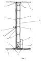
- FIG. 1 and FIG. 3 show a stacker crane with a mast 10 and two with guide elements 2, 2 'equipped chassis 1, 1' for supporting the mast 10.
- the trolleys 1, 1 ' are together with the mast 10 on horizontal rails 4, 4' back and forth ,
- a lift truck 1 "including lifting guide elements 2" is provided, which is vertically displaceable on a lifting rail 4 "by a Hubantriebselement 3.
- the mast 10 is formed from two supports 11, 11 ', which are spaced apart in the direction of movement of the chassis 1, 1' and interconnected by a plurality of transverse bars 12 to form a mast profile, the connection of the transverse bars 12 to the supports 11, 11 '. rigid.
- the supports 11, 11 ' are formed for example of profiles and bolted to their feet on the chassis 1. It can also have more than two supports in this way be provided to form the mast profile.
- the crossbars 12 are rigidly connected to the supports 11, 11 'of the mast 10 via specially designed nodes 13, so that at least a portion of a horizontal force, which results in the main from an acceleration - or deceleration of the stacker crane, or a vertical force, usually a dead load of the stacker crane or the goods to be transported, is derived from a support 11 to the second support 11 '.
- the mast 10 is connected to the two carriages 1, 1 ', wherein a chassis 1 at the head of the mast 10 and a chassis 1' at the foot of the mast 10 is arranged. Due to the lightweight and compact design of the control operating device according to the invention preferably only the lower chassis 1 is driven horizontally by an unspecified drive element.
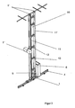
- the truck 1 is guided along the support 11 of the mast 10, wherein a dedicated rail 4" is attached to the support 11.
- the lift truck 1 By guided on both sides of the support 11 Hubantriebselement 3, e.g. a cog belt, the lift truck 1 "is moved and the support 11 is biased, and the risk of buckling of the support 11 due to a bending load caused by the eccentric arrangement of the lift truck is minimized.
- Hubantriebselement 3 e.g. a cog belt
- the Hubantriebselement 3 encloses the support 11 and is spaced on both sides of the inertial center axis of the support 11 so that the moments which are caused by the forces acting in the main in the Hubantriebselement 3 tensile forces, almost cancel.
- a traction drive system which comprises a drive motor 5 and which is arranged within the mast profile between the two outer supports 11, 11 '.
- chassis 1 comprises a lifting drive system, which is also arranged within the mast profile between the two outer supports 11, 11 '.
- the drive motor 5 for driving the horizontal drive element is arranged on the carriage of the chassis 1 in the interior of the mast 10.
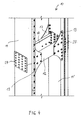
- FIG. 2A the structure of the mast 10 is shown.
- the supports 11, 11 'of the mast 10 designed as profiles are arranged at a distance from one another by the transverse beams 12, two of which are arranged in parallel at the same height.
- the nodes 13 for rigid connection between the crossbar 12 and the respective support 11, 11 ' are formed by gusset plates.
- the profiles of the supports 11, 11 ' are preferably formed as extruded aluminum hollow sections, but can also as in Fig.2 shown executed from corresponding full profiles.
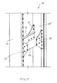
- FIG. 4 shows a compound in a broken mast 10, in which the mast supports 11, 11 'composed of several elements and over parallel lying transverse bars or cross struts 12 are connected.
Landscapes
- Engineering & Computer Science (AREA)
- Transportation (AREA)
- Structural Engineering (AREA)
- Civil Engineering (AREA)
- Life Sciences & Earth Sciences (AREA)
- Geology (AREA)
- Mechanical Engineering (AREA)
- Warehouses Or Storage Devices (AREA)
- Forklifts And Lifting Vehicles (AREA)
Priority Applications (1)
| Application Number | Priority Date | Filing Date | Title |
|---|---|---|---|
| EP16165272.2A EP3088347B1 (fr) | 2008-09-08 | 2009-09-08 | Appareil de commande de rayonnage |
Applications Claiming Priority (2)
| Application Number | Priority Date | Filing Date | Title |
|---|---|---|---|
| AT13932008A AT507335B1 (de) | 2008-09-08 | 2008-09-08 | Regalbediengerät |
| AT0055308U AT11688U1 (de) | 2008-10-02 | 2008-10-02 | Regalbediengerät |
Related Child Applications (1)
| Application Number | Title | Priority Date | Filing Date |
|---|---|---|---|
| EP16165272.2A Division EP3088347B1 (fr) | 2008-09-08 | 2009-09-08 | Appareil de commande de rayonnage |
Publications (2)
| Publication Number | Publication Date |
|---|---|
| EP2161237A2 true EP2161237A2 (fr) | 2010-03-10 |
| EP2161237A3 EP2161237A3 (fr) | 2012-06-27 |
Family
ID=41426166
Family Applications (2)
| Application Number | Title | Priority Date | Filing Date |
|---|---|---|---|
| EP16165272.2A Active EP3088347B1 (fr) | 2008-09-08 | 2009-09-08 | Appareil de commande de rayonnage |
| EP09450162A Ceased EP2161237A3 (fr) | 2008-09-08 | 2009-09-08 | Transstockeur doté d'un mât |
Family Applications Before (1)
| Application Number | Title | Priority Date | Filing Date |
|---|---|---|---|
| EP16165272.2A Active EP3088347B1 (fr) | 2008-09-08 | 2009-09-08 | Appareil de commande de rayonnage |
Country Status (2)
| Country | Link |
|---|---|
| US (1) | US8397645B2 (fr) |
| EP (2) | EP3088347B1 (fr) |
Families Citing this family (11)
| Publication number | Priority date | Publication date | Assignee | Title |
|---|---|---|---|---|
| US8397644B2 (en) * | 2008-09-08 | 2013-03-19 | Swisslog Evomatic Gmbh | Storage and retrieval machine |
| EP3088347B1 (fr) * | 2008-09-08 | 2021-08-04 | Swisslog Evomatic GMBH | Appareil de commande de rayonnage |
| DE102008059711A1 (de) * | 2008-11-29 | 2010-06-10 | Eisenmann Anlagenbau Gmbh & Co. Kg | Vorrichtung zum Umsetzen von Gegenständen sowie Förderanlagen mit einer solchen Vorrichtung |
| WO2010065772A1 (fr) * | 2008-12-03 | 2010-06-10 | Translogic Corporation | Système de stockage et de récupération automatique de température double |
| DE102012000197A1 (de) * | 2012-01-09 | 2013-07-11 | Gebhardt Fördertechnik GmbH | Regalbediengerät zum Ein- und/oder Auslagern von Gütern |
| CN102963840B (zh) * | 2012-11-20 | 2015-03-11 | 无锡海古德新技术有限公司 | 自动叉送机 |
| US9409709B2 (en) | 2013-03-13 | 2016-08-09 | Symbotic, LLC | Automated storage and retrieval system structure |
| JP6256420B2 (ja) * | 2015-06-30 | 2018-01-10 | 村田機械株式会社 | スタッカクレーン |
| DE102020202438A1 (de) | 2020-02-26 | 2021-08-26 | Mias Maschinenbau, Industrieanlagen & Service Gmbh | Mastanordnung für ein regalbediengerät |
| DE102021206764B4 (de) | 2021-06-29 | 2025-05-08 | Gebhardt Fördertechnik GmbH | Regalbediengerät |
| AT525824B1 (de) | 2022-01-15 | 2024-01-15 | Vectron Logistics Gmbh | Mast für ein Regalbediengerät |
Citations (2)
| Publication number | Priority date | Publication date | Assignee | Title |
|---|---|---|---|---|
| DE19631511A1 (de) | 1995-09-04 | 1997-04-03 | Wuestenberg Dieter Prof Dr Ing | Hubmast in Leichtbauweise für ein Regalbediengerät |
| EP1061035A2 (fr) | 1999-06-10 | 2000-12-20 | Murata Kikai Kabushiki Kaisha | Grue gerbeuse |
Family Cites Families (17)
| Publication number | Priority date | Publication date | Assignee | Title |
|---|---|---|---|---|
| US3424322A (en) * | 1965-12-15 | 1969-01-28 | Triax Co | Automatic warehousing system and method |
| GB1187260A (en) * | 1967-12-27 | 1970-04-08 | Wallace James Parker | An Improved Apparatus for Elevating Barrels and also for use in Lowering the Elevated Barrels to Ground Level or on to Lorries |
| US3661280A (en) * | 1969-08-27 | 1972-05-09 | Triax Co | Automatic storage and semi-automated order picking system |
| DE2154709C3 (de) * | 1971-11-04 | 1981-04-09 | Erwin Mehne GmbH & Co, 7100 Heilbronn | Regalförderzeug |
| DE2606074C2 (de) | 1976-02-16 | 1985-04-25 | Inventio Ag, Hergiswil, Nidwalden | Metallmast für Regalfahrzeuge |
| DE3930596A1 (de) * | 1989-09-13 | 1991-03-14 | Konrad Bartscher | Regalfoerderzeug fuer langgut od. dgl. |
| CA2096703A1 (fr) * | 1993-04-02 | 1994-10-03 | Kurt M. Lloyd | Transtockeur automatique |
| US5423652A (en) * | 1994-06-28 | 1995-06-13 | Thiede; Roger C. | Grave marker lifting and setting device |
| DE19534291C2 (de) * | 1995-09-15 | 2002-02-21 | Mannesmann Ag | Regalanlage mit an Schienen geführtem Regalbediengerät |
| JP2002265012A (ja) * | 2001-03-12 | 2002-09-18 | Murata Mach Ltd | スタッカークレーン |
| AT500378B1 (de) * | 2001-06-13 | 2006-12-15 | Tgw Transportgeraete Gmbh | Regalbediengerät |
| AU2003284237A1 (en) * | 2002-10-16 | 2004-05-04 | Transport Systems, Inc. | Monorail sortation system |
| JP4556113B2 (ja) * | 2004-09-09 | 2010-10-06 | 株式会社ダイフク | スタッカークレーン |
| JP4666213B2 (ja) * | 2005-07-05 | 2011-04-06 | 株式会社ダイフク | 物品収納設備 |
| ITBO20070154A1 (it) * | 2007-03-08 | 2008-09-09 | Smv S R L | Sistema per la movimentazione e la stabilizzazione di una base mobile |
| US8397644B2 (en) * | 2008-09-08 | 2013-03-19 | Swisslog Evomatic Gmbh | Storage and retrieval machine |
| EP3088347B1 (fr) * | 2008-09-08 | 2021-08-04 | Swisslog Evomatic GMBH | Appareil de commande de rayonnage |
-
2009
- 2009-09-08 EP EP16165272.2A patent/EP3088347B1/fr active Active
- 2009-09-08 US US12/555,103 patent/US8397645B2/en active Active
- 2009-09-08 EP EP09450162A patent/EP2161237A3/fr not_active Ceased
Patent Citations (2)
| Publication number | Priority date | Publication date | Assignee | Title |
|---|---|---|---|---|
| DE19631511A1 (de) | 1995-09-04 | 1997-04-03 | Wuestenberg Dieter Prof Dr Ing | Hubmast in Leichtbauweise für ein Regalbediengerät |
| EP1061035A2 (fr) | 1999-06-10 | 2000-12-20 | Murata Kikai Kabushiki Kaisha | Grue gerbeuse |
Also Published As
| Publication number | Publication date |
|---|---|
| US20100068022A1 (en) | 2010-03-18 |
| US8397645B2 (en) | 2013-03-19 |
| EP3088347A1 (fr) | 2016-11-02 |
| EP2161237A3 (fr) | 2012-06-27 |
| EP3088347B1 (fr) | 2021-08-04 |
Similar Documents
| Publication | Publication Date | Title |
|---|---|---|
| EP3088347B1 (fr) | Appareil de commande de rayonnage | |
| EP2419365B1 (fr) | Appareil de manipulation et mât pour celui-ci | |
| EP2161236B1 (fr) | Transstockeur avec train de roulement | |
| EP4313836B1 (fr) | Structure porteuse d'un escalier roulant ou d'un tapis roulant | |
| LU86532A1 (de) | Teleskopsaeule | |
| EP3433202B1 (fr) | Engin pourvu d'un système de levage latéral | |
| EP2033932B1 (fr) | Chariot élévateur | |
| DE102006015307A1 (de) | Mobiler Großkran | |
| AT507335B1 (de) | Regalbediengerät | |
| EP2969890B1 (fr) | Chassis de levage pour chariot de manutention | |
| EP4015340A1 (fr) | Châssis d'un véhicule ferroviaire | |
| AT11688U1 (de) | Regalbediengerät | |
| DE102004021708B4 (de) | Vereinfachte Katze mit niedriger Bauhöhe | |
| AT507334B1 (de) | Regalbediengerät | |
| WO2024078841A1 (fr) | Ensemble raccordement de module de section longitudinale et procédé d'assemblage d'appareil à chenille | |
| DE102021206764B4 (de) | Regalbediengerät | |
| AT520889B1 (de) | Heber mit mindestens einer vertikal verfahrbaren Hubplattform mit einem Riemenantrieb | |
| EP3775379B1 (fr) | Pièce tubulaire mobile, tronçon de rail, et ensemble formant un grand huit équipé de ces éléments | |
| WO2021063810A1 (fr) | Support pour un chariot, et dispositif de transport suspendu comprenant un tel support | |
| EP1466861B1 (fr) | mât pour un chariot élévateur | |
| CH616198A5 (en) | Parking facility for motor vehicles | |
| DE10339359A1 (de) | Hubbodenvorrichtung | |
| AT12087U1 (de) | Handhabungsgerät und mast hierfür | |
| WO2024078878A1 (fr) | Système de guidage comprenant au moins trois sections longitudinales, procédé et utilisation | |
| EP4353654A1 (fr) | Dispositif de voie de circulation comportant au moins trois sections longitudinales, procédé et utilisation |
Legal Events
| Date | Code | Title | Description |
|---|---|---|---|
| PUAI | Public reference made under article 153(3) epc to a published international application that has entered the european phase |
Free format text: ORIGINAL CODE: 0009012 |
|
| AK | Designated contracting states |
Kind code of ref document: A2 Designated state(s): AT BE BG CH CY CZ DE DK EE ES FI FR GB GR HR HU IE IS IT LI LT LU LV MC MK MT NL NO PL PT RO SE SI SK SM TR |
|
| AX | Request for extension of the european patent |
Extension state: AL BA RS |
|
| PUAL | Search report despatched |
Free format text: ORIGINAL CODE: 0009013 |
|
| AK | Designated contracting states |
Kind code of ref document: A3 Designated state(s): AT BE BG CH CY CZ DE DK EE ES FI FR GB GR HR HU IE IS IT LI LT LU LV MC MK MT NL NO PL PT RO SE SI SK SM TR |
|
| AX | Request for extension of the european patent |
Extension state: AL BA RS |
|
| RIC1 | Information provided on ipc code assigned before grant |
Ipc: B66F 9/08 20060101ALI20120518BHEP Ipc: B66F 9/07 20060101AFI20120518BHEP |
|
| 17P | Request for examination filed |
Effective date: 20121227 |
|
| 17Q | First examination report despatched |
Effective date: 20130726 |
|
| APBK | Appeal reference recorded |
Free format text: ORIGINAL CODE: EPIDOSNREFNE |
|
| APBN | Date of receipt of notice of appeal recorded |
Free format text: ORIGINAL CODE: EPIDOSNNOA2E |
|
| APBR | Date of receipt of statement of grounds of appeal recorded |
Free format text: ORIGINAL CODE: EPIDOSNNOA3E |
|
| APAF | Appeal reference modified |
Free format text: ORIGINAL CODE: EPIDOSCREFNE |
|
| APAF | Appeal reference modified |
Free format text: ORIGINAL CODE: EPIDOSCREFNE |
|
| APAF | Appeal reference modified |
Free format text: ORIGINAL CODE: EPIDOSCREFNE |
|
| APBT | Appeal procedure closed |
Free format text: ORIGINAL CODE: EPIDOSNNOA9E |
|
| STAA | Information on the status of an ep patent application or granted ep patent |
Free format text: STATUS: THE APPLICATION HAS BEEN REFUSED |
|
| 18R | Application refused |
Effective date: 20160414 |