EP2161237A2 - Stacker crane with a mast - Google Patents
Stacker crane with a mast Download PDFInfo
- Publication number
- EP2161237A2 EP2161237A2 EP09450162A EP09450162A EP2161237A2 EP 2161237 A2 EP2161237 A2 EP 2161237A2 EP 09450162 A EP09450162 A EP 09450162A EP 09450162 A EP09450162 A EP 09450162A EP 2161237 A2 EP2161237 A2 EP 2161237A2
- Authority
- EP
- European Patent Office
- Prior art keywords
- mast
- supports
- storage
- retrieval unit
- unit according
- Prior art date
- Legal status (The legal status is an assumption and is not a legal conclusion. Google has not performed a legal analysis and makes no representation as to the accuracy of the status listed.)
- Ceased
Links
- 229910052751 metal Inorganic materials 0.000 claims abstract description 3
- 239000002184 metal Substances 0.000 claims abstract description 3
- 238000003860 storage Methods 0.000 claims description 26
- 230000003068 static effect Effects 0.000 claims description 4
- 238000005452 bending Methods 0.000 abstract description 6
- 239000000463 material Substances 0.000 description 5
- 230000001133 acceleration Effects 0.000 description 3
- 229910052782 aluminium Inorganic materials 0.000 description 3
- XAGFODPZIPBFFR-UHFFFAOYSA-N aluminium Chemical compound [Al] XAGFODPZIPBFFR-UHFFFAOYSA-N 0.000 description 3
- 230000002411 adverse Effects 0.000 description 2
- 238000010276 construction Methods 0.000 description 2
- 210000001503 joint Anatomy 0.000 description 2
- 229910000831 Steel Inorganic materials 0.000 description 1
- 230000006978 adaptation Effects 0.000 description 1
- 230000005540 biological transmission Effects 0.000 description 1
- 230000015572 biosynthetic process Effects 0.000 description 1
- 150000001875 compounds Chemical class 0.000 description 1
- 230000001934 delay Effects 0.000 description 1
- 230000000694 effects Effects 0.000 description 1
- 230000002349 favourable effect Effects 0.000 description 1
- 238000004519 manufacturing process Methods 0.000 description 1
- 238000005457 optimization Methods 0.000 description 1
- 230000002265 prevention Effects 0.000 description 1
- 239000007787 solid Substances 0.000 description 1
- 239000010959 steel Substances 0.000 description 1
- 239000000725 suspension Substances 0.000 description 1
- 238000009827 uniform distribution Methods 0.000 description 1
- 238000011144 upstream manufacturing Methods 0.000 description 1
- 239000013585 weight reducing agent Substances 0.000 description 1
Images

Classifications
-
- B—PERFORMING OPERATIONS; TRANSPORTING
- B66—HOISTING; LIFTING; HAULING
- B66F—HOISTING, LIFTING, HAULING OR PUSHING, NOT OTHERWISE PROVIDED FOR, e.g. DEVICES WHICH APPLY A LIFTING OR PUSHING FORCE DIRECTLY TO THE SURFACE OF A LOAD
- B66F9/00—Devices for lifting or lowering bulky or heavy goods for loading or unloading purposes
- B66F9/06—Devices for lifting or lowering bulky or heavy goods for loading or unloading purposes movable, with their loads, on wheels or the like, e.g. fork-lift trucks
- B66F9/07—Floor-to-roof stacking devices, e.g. "stacker cranes", "retrievers"
-
- B—PERFORMING OPERATIONS; TRANSPORTING
- B66—HOISTING; LIFTING; HAULING
- B66F—HOISTING, LIFTING, HAULING OR PUSHING, NOT OTHERWISE PROVIDED FOR, e.g. DEVICES WHICH APPLY A LIFTING OR PUSHING FORCE DIRECTLY TO THE SURFACE OF A LOAD
- B66F9/00—Devices for lifting or lowering bulky or heavy goods for loading or unloading purposes
- B66F9/06—Devices for lifting or lowering bulky or heavy goods for loading or unloading purposes movable, with their loads, on wheels or the like, e.g. fork-lift trucks
- B66F9/075—Constructional features or details
- B66F9/08—Masts; Guides; Chains
Definitions
- the invention relates to a storage and retrieval unit with a mast, at least one chassis for holding the mast, at least one rail on which the at least one chassis is movable back and forth, and at least one on the mast vertically movable pallet truck.
- Stacker cranes are for example in the publications DE 196 31 511 A1 and EP 1 061 035 A2 described.
- a mast of a stacker crane is described in lightweight construction, which is tapered upwards.
- the described mast is further designed so that the mast interior can be used for internals.
- EP 1 061 035 A2 describes a mast of a stacker crane, which consists of a solid profile and an upstream truss bearer.
- the lifting drive element which runs e.g. is formed in the form of a toothed belt, on one side of the mast, which is exposed by the resulting bias of a permanent bending load, which leads to a disadvantage in terms of device static and positioning accuracy.
- the object of the invention is therefore to provide a stacker crane with the lightest possible and yet stable mast, so as to keep the main dynamic loads that are caused by the acceleration and deceleration of the stacker crane on the elements of the stacker crane as low as possible. It is to be ensured that the occurring vertical and horizontal forces in the mast are derived in an efficient manner in the chassis.
- Another object of the invention is to provide a storage and retrieval unit, which minimizes the Mastverbiegonne under load by lifting movements.
- the height of the mast should not be limited by predetermined component dimensions, but a modular design make it possible to achieve different mast heights as needed, with heights of over twenty meters without adverse consequences for the mobility of the stacker crane should be achievable.
- the mast is formed from at least two supports, which are spaced apart in the direction of movement of the at least one chassis and interconnected by at least one crossbar to a mast profile, wherein the connection of the at least one crossbar to the supports is designed rigid ,
- the formation of the mast by two or more supports creates a for the operation of the Storage and retrieval unit advantageous weight reduction.
- the supports are assembled via one or more crossbars to a mast profile, which receives dynamic loads both longitudinally and transversely through the preferably two supports, which only happens through the rigid connection of the crossbeam in the direction of travel, which also acting on a support Transverse forces are partially taken over by the second support. Due to the much lower loads transverse to the direction of travel, the width of the mast can therefore be reduced. This makes it possible to choose a profile shape of the supports in the mast so that they correspond substantially to the width of the mast.
- Another advantage is the easily realizable modular composability of the columns to very tall masts.
- a preferred embodiment of the stacker crane can thus be that the at least one crossbar is connected via rigidly arranged nodes at its ends to the supports of the mast, so that a static and / or dynamic force which acts on one of the at least two supports, at least one Share is taken by another of the supports.
- the passing of occurring loads of a profile or a support of the mast to another support causes an approximately uniform distribution of the loads between the supports and thus creates a relief of the support, along which the pallet truck is guided.
- the supports can thus be designed as significantly less loaded elements, that is a lighter material with lower strength such as aluminum and / or with a smaller cross-section.
- the connection of the crossbar is made by a specially trained gusset plate, which in reference to the desired Force transmission, but also in terms of static and dynamic properties of the mast is designed.
- the mast is preferably made of individual modules which are connected by screw connections.
- the butt joint of the individual profiles is designed as a screw connection and is preferably provided in the respective region of the gusset plate for the transverse bar.
- the mast is preferably attached to the carriage of the chassis by a screw connection, which is designed by a specially trained mast base on the respective columns of the mast.
- connection forms which are known to the person skilled in the art are not excluded for connection of the mast to the carriage or for connecting the individual modules of the mast.
- a possible embodiment of the stacker crane may be that along at least one of the columns of the mast forming profiles of the truck is performed.
- a possible embodiment of the storage and retrieval unit may consist in that the at least one chassis comprises a traction drive system which is arranged within the mast profile between the two outer supports. In this way, a relative to the rail in the longitudinal direction of the central guide of the traction drive belt and thus a rail-near and centric train is possible. At the same time there is a favorable weight load in the middle between the mast supports.
- the at least one chassis comprises a lifting drive system which is arranged within the mast profile between the two outer supports and optionally that the traction drive system and / or the Hubantriebssystem is arranged centrally in the direction of movement of the chassis.
- This arrangement has an advantageous effect on the thereby achievable central course of the Hubantriebselements.
- the drive motor of the Hubfahrwerkes which is guided vertically along the mast, is advantageously arranged on the lower, horizontal chassis of the mast within the columns of the mast, since thereby the horizontal chassis of the mast can be made shorter. By the latter, the work area of the stacker crane is increased.
- Another embodiment of the storage and retrieval device according to the invention may consist in that the lifting carriage, which is movable by means of a lifting drive element, is guided along one of the two supports and that the lifting drive element is guided around a support.
- the profile forming the support can thus be dimensioned smaller, that is, made of a lighter but a material with lower strength and / or with a smaller cross-section.
- the invention may be provided at the base and at the head of a support deflections for the Hubantriebselement, wherein the Hubantriebselement is passed at the base by a through hole of the support and wherein the Hubantriebselement is guided on both sides of a support of the mast.
- the one support of the mast enclosing Hubantriebselement is biased, whereby the mast is acted upon symmetrically with a compressive stress.
- a bias of a mast support of the stacker crane according to the invention can be carried out in that at least one of the columns of the mast forming profiles is biased by the leadership of the drive belt.
- This bias thus causes that support along which the lift truck is guided, undergoes no bending stress, since the tensile stresses of the bias of the support is superimposed.
- the support can be loaded higher due to this bias or be dimensioned weaker in the form of a cross-sectional reduction or by the choice of a light, but material with lower strength.
- the Hubantriebselement can be formed for example by a drive belt or a drive belt.
- a permanent connection of the mast supports with the chassis can be that the supports are screwed at their feet on the chassis.
- the supports of the mast are each composed of a plurality of support elements, which are grooved together at their ends, the supports are preferably formed by profiles, in particular light metal profiles.
- a preferred embodiment of the stacker crane may be that the rail of the guided on the mast Hubfahrtechnikes is attached to at least one of the columns of the mast forming profiles.
- the rails of the landing gear guided on the mast are attached to the supports so that an off-center loading of the support is largely avoided.
- the arrangement of the support is related to the optimization of the cross-sectional shape of the profile forming the support.
- the means of attachment of the vertical rail should be chosen so that an adjustability of the rail is easily possible at any time.
- the profile forming the support of the mast also serves as a rail.
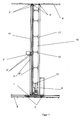
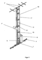
- FIG. 1 and FIG. 3 show a stacker crane with a mast 10 and two with guide elements 2, 2 'equipped chassis 1, 1' for supporting the mast 10.
- the trolleys 1, 1 ' are together with the mast 10 on horizontal rails 4, 4' back and forth ,
- a lift truck 1 "including lifting guide elements 2" is provided, which is vertically displaceable on a lifting rail 4 "by a Hubantriebselement 3.
- the mast 10 is formed from two supports 11, 11 ', which are spaced apart in the direction of movement of the chassis 1, 1' and interconnected by a plurality of transverse bars 12 to form a mast profile, the connection of the transverse bars 12 to the supports 11, 11 '. rigid.
- the supports 11, 11 ' are formed for example of profiles and bolted to their feet on the chassis 1. It can also have more than two supports in this way be provided to form the mast profile.
- the crossbars 12 are rigidly connected to the supports 11, 11 'of the mast 10 via specially designed nodes 13, so that at least a portion of a horizontal force, which results in the main from an acceleration - or deceleration of the stacker crane, or a vertical force, usually a dead load of the stacker crane or the goods to be transported, is derived from a support 11 to the second support 11 '.
- the mast 10 is connected to the two carriages 1, 1 ', wherein a chassis 1 at the head of the mast 10 and a chassis 1' at the foot of the mast 10 is arranged. Due to the lightweight and compact design of the control operating device according to the invention preferably only the lower chassis 1 is driven horizontally by an unspecified drive element.
- the truck 1 is guided along the support 11 of the mast 10, wherein a dedicated rail 4" is attached to the support 11.
- the lift truck 1 By guided on both sides of the support 11 Hubantriebselement 3, e.g. a cog belt, the lift truck 1 "is moved and the support 11 is biased, and the risk of buckling of the support 11 due to a bending load caused by the eccentric arrangement of the lift truck is minimized.
- Hubantriebselement 3 e.g. a cog belt
- the Hubantriebselement 3 encloses the support 11 and is spaced on both sides of the inertial center axis of the support 11 so that the moments which are caused by the forces acting in the main in the Hubantriebselement 3 tensile forces, almost cancel.
- a traction drive system which comprises a drive motor 5 and which is arranged within the mast profile between the two outer supports 11, 11 '.
- chassis 1 comprises a lifting drive system, which is also arranged within the mast profile between the two outer supports 11, 11 '.
- the drive motor 5 for driving the horizontal drive element is arranged on the carriage of the chassis 1 in the interior of the mast 10.
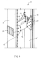
- FIG. 2A the structure of the mast 10 is shown.
- the supports 11, 11 'of the mast 10 designed as profiles are arranged at a distance from one another by the transverse beams 12, two of which are arranged in parallel at the same height.
- the nodes 13 for rigid connection between the crossbar 12 and the respective support 11, 11 ' are formed by gusset plates.
- the profiles of the supports 11, 11 ' are preferably formed as extruded aluminum hollow sections, but can also as in Fig.2 shown executed from corresponding full profiles.
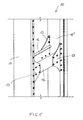
- FIG. 4 shows a compound in a broken mast 10, in which the mast supports 11, 11 'composed of several elements and over parallel lying transverse bars or cross struts 12 are connected.
Landscapes
- Engineering & Computer Science (AREA)
- Transportation (AREA)
- Structural Engineering (AREA)
- Civil Engineering (AREA)
- Life Sciences & Earth Sciences (AREA)
- Geology (AREA)
- Mechanical Engineering (AREA)
- Warehouses Or Storage Devices (AREA)
- Forklifts And Lifting Vehicles (AREA)
Abstract
Description
Die Erfindung betrifft ein Regalbediengerät mit einem Mast, zumindest einem Fahrwerk zur Halterung des Mastes, zumindest einer Schiene, auf der das zumindest eine Fahrwerk hin- und her bewegbar ist, sowie zumindest einem auf dem Mast vertikal verschiebbaren Hubwagen.The invention relates to a storage and retrieval unit with a mast, at least one chassis for holding the mast, at least one rail on which the at least one chassis is movable back and forth, and at least one on the mast vertically movable pallet truck.
Durch das starke Wachstum des Versandhandels, nicht zuletzt durch den Verkauf von Waren über das Internet hervorgerufen, ergeben sich erhöhte Anforderungen an die Bewältigung von Material- und Warenflüssen innerhalb eines Betriebsgeländes. Hochregallager und automatische Kleinteilelager, die über Regalbediengeräte zugänglich sind, stellen dafür die Grundlage dar.Due to the strong growth of the mail order business, not least due to the sale of goods via the Internet, there are increased demands on the management of material and goods flows within a company premises. High-bay warehouses and automatic small parts warehouses accessible via stacker cranes represent the basis for this.
Regalbediengeräte sind beispielsweise in den Druckschriften
In der
Üblicherweise verläuft das Hubantriebselement, das z.B. in Form eines Zahnriemens ausgebildet ist, auf einer Seite des Mastes, welcher durch die resultierende Vorspannung einer permanenten Biegebelastung ausgesetzt ist, was zu einem Nachteil hinsichtlich der Gerätestatik und Positioniergenauigkeit führt.Usually the lifting drive element, which runs e.g. is formed in the form of a toothed belt, on one side of the mast, which is exposed by the resulting bias of a permanent bending load, which leads to a disadvantage in terms of device static and positioning accuracy.
Ein weiterer Nachteil der Masten bekannter Regalbediengeräte ist durch ihr hohes Eigengewicht gegeben, welches die Energiekosten erhöht und in vielen Fällen auch eine Beschränkung in der Masthöhe mit sich bringt.Another disadvantage of the masts known storage and retrieval machines is due to their high Self-weight given, which increases the energy costs and in many cases also brings a restriction in the mast height.
Aufgabe der Erfindung ist es daher, ein Regalbediengerät mit einem möglichst leichten und trotzdem stabilen Mast zu schaffen, um so die in der Hauptsache dynamischen Belastungen, die durch das Beschleunigen und Abbremsen des Regalbediengerätes hervorgerufen werden, auf die Elemente des Regalbediengerätes möglichst gering zu halten. Es soll gewährleistet werden, dass die auftretenden vertikalen und horizontalen Kräfte im Mast auf eine effiziente Weise in das Fahrwerk abgeleitet werden.The object of the invention is therefore to provide a stacker crane with the lightest possible and yet stable mast, so as to keep the main dynamic loads that are caused by the acceleration and deceleration of the stacker crane on the elements of the stacker crane as low as possible. It is to be ensured that the occurring vertical and horizontal forces in the mast are derived in an efficient manner in the chassis.
Weitere Aufgabe der Erfindung ist es, ein Regalbediengerät anzugeben, welches die Mastverbiegungen bei Belastung durch Hubbewegungen minimiert.Another object of the invention is to provide a storage and retrieval unit, which minimizes the Mastverbiegungen under load by lifting movements.
Weiters soll die Bauhöhe des Mastes nicht durch vorgegebene Bauteilmaße beschränkt sein, sondern eine modulare Bauweise es ermöglichen, je nach Bedarf unterschiedliche Masthöhen zu erreichen, wobei Bauhöhen von über zwanzig Metern ohne nachteilige Folgen für die Verfahrbarkeit des Regalbediengerätes erreichbar sein sollen.Furthermore, the height of the mast should not be limited by predetermined component dimensions, but a modular design make it possible to achieve different mast heights as needed, with heights of over twenty meters without adverse consequences for the mobility of the stacker crane should be achievable.
Schließlich ist es Ziel der Erfindung, eine derartige Anordnung von Antriebssystemen zu ermöglichen, dass asymmetrische Belastungen des Fahrwerks und des Mastes verhindert werden.Finally, it is an object of the invention to allow such an arrangement of drive systems that asymmetric loads on the chassis and the mast are prevented.
Erfindungsgemäß wird dies dadurch gelöst, dass der Mast aus zumindest zwei Stützen gebildet ist, welche in Bewegungsrichtung des zumindest einen Fahrwerks voneinander beabstandet und durch zumindest einen Querbalken zu einem Mastprofil miteinander verbunden sind, wobei die Anbindung des zumindest einen Querbalkens an die Stützen biegesteif ausgeführt ist.According to the invention this is achieved in that the mast is formed from at least two supports, which are spaced apart in the direction of movement of the at least one chassis and interconnected by at least one crossbar to a mast profile, wherein the connection of the at least one crossbar to the supports is designed rigid ,
Die Ausbildung des Mastes durch zwei oder mehrere Stützen, welche an die auftretenden Belastungen optimiert sind, schafft eine für den Betrieb des Regalbediengerätes vorteilhafte Gewichtsreduktion. Die Stützen sind über einen oder mehrere Querbalken zu einem Mastprofil zusammengesetzt, welches dynamische Belastungen sowohl in Längs- als auch in Querrichtung durch die vorzugsweise zwei Stützen aufnimmt, was allein durch die biegesteife Anbindung des Querbalkens in Fahrtrichtung geschieht, wobei auch die auf eine Stütze wirkenden Querkräfte von der zweiten Stütze teilweise übernommen werden. Durch die wesentlich geringeren Belastungen quer zur Fahrtrichtung kann die Breite des Mastes daher reduziert werden. Dadurch ist es möglich, eine Profilform der Stützen im Mast so zu wählen, dass sie im wesentlichen der Breite des Mastes entsprechen.The formation of the mast by two or more supports, which are optimized for the loads occurring creates a for the operation of the Storage and retrieval unit advantageous weight reduction. The supports are assembled via one or more crossbars to a mast profile, which receives dynamic loads both longitudinally and transversely through the preferably two supports, which only happens through the rigid connection of the crossbeam in the direction of travel, which also acting on a support Transverse forces are partially taken over by the second support. Due to the much lower loads transverse to the direction of travel, the width of the mast can therefore be reduced. This makes it possible to choose a profile shape of the supports in the mast so that they correspond substantially to the width of the mast.
Bedingt durch die Verbindung der Maststützen mit einem oder mehreren Querbalken ergibt sich eine sehr leichte Bauweise und zudem die Möglichkeit der vorteilhaften, zentralen Anordnung von Fahrwerks- und Antriebskomponenten im Zwischenraum zwischen den Maststützen.Due to the connection of the mast supports with one or more crossbars results in a very lightweight design and also the possibility of advantageous, central arrangement of suspension and drive components in the space between the mast columns.
Weiterer Vorteil ist die einfach verwirklichbare modulare Zusammensetzbarkeit der Stützen zu sehr hohen Masten.Another advantage is the easily realizable modular composability of the columns to very tall masts.
Eine bevorzugte Ausführungsform des Regalbediengerätes kann somit sein, dass der zumindest eine Querbalken über an seinen Enden angeordnete Knoten biegesteif an die Stützen des Mastes angebunden ist, sodass eine statische und/oder dynamische Kraft, welche an einer der zumindest zwei Stützen angreift, zumindest zu einem Anteil von einer anderen der Stützen aufgenommen wird.A preferred embodiment of the stacker crane can thus be that the at least one crossbar is connected via rigidly arranged nodes at its ends to the supports of the mast, so that a static and / or dynamic force which acts on one of the at least two supports, at least one Share is taken by another of the supports.
Die Weitergabe von auftretenden Belastungen von einem Profil beziehungsweise einer Stütze des Mastes zu einer weiteren Stütze bewirkt eine in etwa gleichmäßige Verteilung der Lasten zwischen den Stützen und schafft somit eine Entlastung der Stütze, entlang welcher der Hubwagen geführt ist. Die Stützen können somit als deutlich geringer belastete Elemente, das heißt einem leichteren Werkstoff mit geringerer Festigkeit wie beispielsweise Aluminium und/oder mit einem geringeren Querschnitt ausgebildet werden. Die Anbindung des Querbalkens erfolgt durch ein speziell ausgebildetes Knotenblech, welches in Bezugnahme auf die gewünschte Kraftweiterleitung, aber auch in Bezug auf die statischen und dynamischen Eigenschaften des Mastes ausgelegt ist.The passing of occurring loads of a profile or a support of the mast to another support causes an approximately uniform distribution of the loads between the supports and thus creates a relief of the support, along which the pallet truck is guided. The supports can thus be designed as significantly less loaded elements, that is a lighter material with lower strength such as aluminum and / or with a smaller cross-section. The connection of the crossbar is made by a specially trained gusset plate, which in reference to the desired Force transmission, but also in terms of static and dynamic properties of the mast is designed.
Der Mast besteht vorzugsweise aus einzelnen Modulen, die durch Schraubverbindungen verbunden sind. Dadurch ist auch eine einfache und vor allem auch kostengünstige Anpassung des Mastes an unterschiedlich geforderte Bauhöhen möglich. Dies wird auch vor allem dadurch erreicht, dass auf Grund der kleineren Profilabmessungen die Werkzeugkosten für die Profilherstellung geringer sind und weiters auch geringere Abnahmemengen im Gegensatz zu Stahlrollprofilen möglich sind. Die Stoßverbindung der einzelnen Profile ist als Schraubverbindung ausgeführt und vorzugsweise im jeweiligen Bereich des Knotenbleches für den Querbalken vorgesehen.The mast is preferably made of individual modules which are connected by screw connections. As a result, a simple and, above all, cost-effective adaptation of the mast to different required heights is possible. This is also achieved in particular by the fact that due to the smaller profile dimensions, the tooling costs for the profile production are lower and, furthermore, lower purchase quantities are possible in contrast to steel roller profiles. The butt joint of the individual profiles is designed as a screw connection and is preferably provided in the respective region of the gusset plate for the transverse bar.
Der Mast ist vorzugsweise am Schlitten des Fahrwerks durch eine Schraubverbindung befestigt, die durch einen speziell ausgebildeten Mastfuß an den jeweiligen Stützen des Mastes ausgeführt ist.The mast is preferably attached to the carriage of the chassis by a screw connection, which is designed by a specially trained mast base on the respective columns of the mast.
Im Rahmen dieser Erfindung sind Verbindungsformen, welche dem Fachmann bekannt sind, zur Anbindung des Mastes am Schlitten beziehungsweise zum Verbinden der einzelnen Module des Mastes nicht ausgeschlossen.In the context of this invention, connection forms which are known to the person skilled in the art are not excluded for connection of the mast to the carriage or for connecting the individual modules of the mast.
Eine mögliche Ausführungsform des Regalbediengerätes kann sein, dass entlang zumindest eines der die Stützen des Mastes bildenden Profile der Hubwagen geführt ist.A possible embodiment of the stacker crane may be that along at least one of the columns of the mast forming profiles of the truck is performed.
Eine mögliche Ausführungsform des Regalbediengerätes kann darin bestehen, dass das zumindest eine Fahrwerk ein Fahrantriebssystem umfasst, das innerhalb des Mastprofils zwischen den zwei außen liegenden Stützen angeordnet ist. Auf diese Weise ist eine gegenüber der Schiene in Längsrichtung mittige Führung des Fahrantriebsriemens und damit ein schienennaher und zentrischer Zug möglich. Zugleich liegt eine günstige Gewichtsbelastung in der Mitte zwischen den Maststützen vor.A possible embodiment of the storage and retrieval unit may consist in that the at least one chassis comprises a traction drive system which is arranged within the mast profile between the two outer supports. In this way, a relative to the rail in the longitudinal direction of the central guide of the traction drive belt and thus a rail-near and centric train is possible. At the same time there is a favorable weight load in the middle between the mast supports.
Es kann in diesem Zusammenhang auch vorgesehen sein, dass das zumindest eine Fahrwerk ein Hubantriebssystem umfasst, das innerhalb des Mastprofils zwischen den zwei außen liegenden Stützen angeordnet ist und gegebenenfalls, dass das Fahrantriebssystem und/oder das Hubantriebssystem in Bewegungsrichtung des Fahrwerks mittig angeordnet ist. Diese Anordnung wirkt sich auf den dadurch realisierbaren mittigen Verlauf des Hubantriebselements vorteilhaft aus.It may also be provided in this context that the at least one chassis comprises a lifting drive system which is arranged within the mast profile between the two outer supports and optionally that the traction drive system and / or the Hubantriebssystem is arranged centrally in the direction of movement of the chassis. This arrangement has an advantageous effect on the thereby achievable central course of the Hubantriebselements.
Der Antriebsmotor des Hubfahrwerkes, welches vertikal entlang des Mastes geführt wird, ist vorteilhaft am unteren, horizontalen Fahrwerk des Mastes innerhalb der Stützen des Mastes angeordnet, da dadurch das horizontale Fahrwerk des Mastes kürzer ausgebildet werden kann. Durch letzteres wird der Arbeitsbereich des Regalbediengerätes vergrößert.The drive motor of the Hubfahrwerkes, which is guided vertically along the mast, is advantageously arranged on the lower, horizontal chassis of the mast within the columns of the mast, since thereby the horizontal chassis of the mast can be made shorter. By the latter, the work area of the stacker crane is increased.
Eine weitere Ausführungsform des erfindungsgemäßen Regalbediengeräts kann darin bestehen, dass der mittels eines Hubantriebselements bewegbare Hubwagen entlang einer der zwei Stützen geführt ist und dass das Hubantriebselement die eine Stütze umschließend geführt ist.Another embodiment of the storage and retrieval device according to the invention may consist in that the lifting carriage, which is movable by means of a lifting drive element, is guided along one of the two supports and that the lifting drive element is guided around a support.
Diese an beiden Seiten zumindest eine Stütze umschließende Führung des Antriebselementes des Hubwagens, der vertikal am Mast geführt wird, schafft den Vorteil, dass die Spannungen im Mast und Mastfuß günstig beeinflusst werden. Durch den damit erreichbaren zentrischen Zug entsteht eine symmetrische Verformung, welche die Torsionsbelastung des Mastes stark herabsetzt. Dadurch wird die zumindest eine Stütze des Mastes vorwiegend auf Druck belastet und kaum einer Biegebelastung ausgesetzt. Diese durch das Antriebselement am Mast hervorgerufene Vorspannung wirkt sich vor allem bei der dynamischen Fahrt vorteilhaft aus.This on both sides at least one support enclosing leadership of the drive element of the lift truck, which is guided vertically on the mast, creates the advantage that the stresses in the mast and mast base are favorably influenced. By the thus achievable centric train creates a symmetrical deformation, which greatly reduces the torsional load of the mast. As a result, the at least one support of the mast is predominantly subjected to pressure and hardly exposed to a bending load. This caused by the drive element on the mast bias affects especially in the dynamic ride advantageous.
Das die Stütze bildende Profil kann somit schwächer dimensioniert, das heißt aus einem leichteren, jedoch einem Werkstoff mit geringerer Festigkeit und/oder mit einem geringerem Querschnitt gebildet werden.The profile forming the support can thus be dimensioned smaller, that is, made of a lighter but a material with lower strength and / or with a smaller cross-section.
Gemäß einer Weiterbildung der Erfindung können am Fußpunkt und am Kopfpunkt der einen Stütze Umlenkungen für das Hubantriebselement vorgesehen sein, wobei das Hubantriebselement am Fußpunkt durch eine Durchgangsöffnung der Stütze hindurchgeführt ist und wobei das Hubantriebselement an beiden Seiten der einen Stütze des Mastes geführt ist.According to one embodiment of the invention may be provided at the base and at the head of a support deflections for the Hubantriebselement, wherein the Hubantriebselement is passed at the base by a through hole of the support and wherein the Hubantriebselement is guided on both sides of a support of the mast.
Es ergibt sich dadurch neben der Verringerung der asymmetrischen Belastungen und dem Verhindern von unerwünschten Spannungsüberlagerungen eine stark verbesserte Platzsituation im Bereich der Hubschlittenführung.This results in addition to the reduction of asymmetric loads and the prevention of unwanted voltage overlays a greatly improved space in the Hubschlittenführung.
Weiters kann in diesem Zusammenhang vorgesehen sein, dass das die eine Stütze des Mastes umschließende Hubantriebselement vorgespannt ist, wodurch der Mast symmetrisch mit einer Druckspannung beaufschlagt ist.Furthermore, it may be provided in this context that the one support of the mast enclosing Hubantriebselement is biased, whereby the mast is acted upon symmetrically with a compressive stress.
Eine Vorspannung einer Maststütze des erfindungsgemäßen Regalbediengerätes kann dadurch ausgeführt sein, dass zumindest eines der die Stützen des Mastes bildenden Profile durch die Führung des Antriebsgurtes vorgespannt ist.A bias of a mast support of the stacker crane according to the invention can be carried out in that at least one of the columns of the mast forming profiles is biased by the leadership of the drive belt.
Diese Vorspannung bewirkt somit, dass jene Stütze, entlang welcher der Hubwagen geführt ist, keine Biegebelastung erfährt, da die Zugspannungen von der Vorspannung der Stütze überlagert ist. Die Stütze kann aufgrund dieser Vorspannung höher belastet werden beziehungsweise schwächer in Form einer Querschnittsreduktion oder durch die Wahl eines leichten, jedoch Materials mit geringerer Festigkeit dimensioniert werden.This bias thus causes that support along which the lift truck is guided, undergoes no bending stress, since the tensile stresses of the bias of the support is superimposed. The support can be loaded higher due to this bias or be dimensioned weaker in the form of a cross-sectional reduction or by the choice of a light, but material with lower strength.
Das Hubantriebselement kann beispielweise durch einen Antriebsgurt oder einen Antriebsriemen gebildet sein.The Hubantriebselement can be formed for example by a drive belt or a drive belt.
Es sei im Rahmen dieser Erfindung nicht ausgeschlossen, dass das Hubfahrwerk des Regalbediengerätes durch andere, dem Fachmann bekannte Mittel sowie eine Kombination dieser Mittel angetrieben wird.It is not excluded in the context of this invention that the Hubfahrwerk the stacker crane is driven by other means known in the art and a combination of these means.
Eine dauerhafte Verbindung der Maststützen mit dem Fahrwerk kann darin bestehen, dass die Stützen an ihren Fußpunkten auf dem Fahrwerk angeschraubt sind.A permanent connection of the mast supports with the chassis can be that the supports are screwed at their feet on the chassis.
Zur Ermöglichung einer modularen Bauweise und einer möglichst großen Bauhöhe kann vorgesehen sein, dass die Stützen des Mastes jeweils aus mehreren Stützenelementen zusammengesetzt sind, die an ihren Enden miteinander vernutet sind, wobei die Stützen bevorzugt durch Profile, insbesondere Leichtmetallprofile gebildet sind.To enable a modular design and the largest possible height can be provided that the supports of the mast are each composed of a plurality of support elements, which are grooved together at their ends, the supports are preferably formed by profiles, in particular light metal profiles.
Eine bevorzugte Ausführungsform des Regalbediengerätes kann sein, dass die Schiene des am Mast geführten Hubfahrwerkes an zumindest einem der die Stützen des Mastes bildenden Profile befestigt ist.A preferred embodiment of the stacker crane may be that the rail of the guided on the mast Hubfahrwerkes is attached to at least one of the columns of the mast forming profiles.
Die Schienen des am Mast geführten Fahrwerkes sind so an den Stützen befestigt, dass eine außermittige Belastung der Stütze weitgehendst vermieden wird. Die Anordnung der Stütze steht im Zusammenhang mit der Optimierung der Querschnittsform des die Stütze bildenden Profils. Die Mittel der Befestigung der vertikalen Schiene sind so zu wählen, dass eine Justierbarkeit der Schiene jederzeit leicht möglich ist.The rails of the landing gear guided on the mast are attached to the supports so that an off-center loading of the support is largely avoided. The arrangement of the support is related to the optimization of the cross-sectional shape of the profile forming the support. The means of attachment of the vertical rail should be chosen so that an adjustability of the rail is easily possible at any time.
Im Rahmen dieser Erfindung ist es auch möglich, dass das die Stütze des Mastes bildende Profil auch als Schiene dient.In the context of this invention, it is also possible that the profile forming the support of the mast also serves as a rail.
Durch diese optimierte erfindungsgemäße Ausgestaltung der Mastkonstruktion können Bauhöhen bis zu 24 Meter und mehr erreicht sowie hohe Beschleunigungen bzw. Verzögerungen beim Fahrbetrieb des Regalbediengerätes bewältigt werden ohne dass die Positioniergenauigkeit nachteilig beeinflusst wird.By this optimized inventive design of the mast construction heights up to 24 meters and more can be achieved and high accelerations or delays in driving the storage and retrieval unit to be handled without the positioning accuracy is adversely affected.
Weiters wird durch die bevorzugte Verwendung von Schraubverbindungen gegenüber Schweißkonstruktionen die Produktlebensdauer erhöht, da dadurch Dauerfestigkeitsprobleme, wie sie bei Schweißnähten auftreten, nahezu eliminiert werden. Zusätzliche Vorteile ergeben sich auch bei der Montage, da einzelne Baugruppen vormontiert, leicht transportiert und am Aufstellungsort einfach zusammengebaut und ggf. justiert werden können.Furthermore, the preferred use of threaded joints over welded structures increases product life by virtually eliminating fatigue problems associated with welds become. Additional advantages also arise during assembly, as individual modules pre-assembled, easily transported and can be easily assembled at the site and possibly adjusted.
Nachfolgend wird die Erfindung anhand der in den Zeichnungen dargestellten Ausführungsbeispiele eingehend erläutert. Es zeigt dabei
-
Fig.1 eine schematische Seitenansicht einer Ausführungsform des erfindungsgemäßen Regalbediengerätes; -
Fig. 2A einen horizontalen Schnitt durch dieAusführungsform gemäß Figur 1 ; -
Fig.2B einen horizontalen Schnitt durch eine weitere Ausführungsform des erfindungsgemäßen Regalbediengeräts; -
Fig. 3 eine schaubildliche (dreidimensionale) Darstellung der inFigur 1 -
Fig. 4 eine dreidimensionale Ansicht eines Details einer weiteren Ausführungsform des erfindungsgemäßen Regalbediengeräts und -
Fig.5 eine dreidimensionale Ansicht eines Details einer weiteren Ausführungsform des erfindungsgemäßen Regalbediengeräts.
-
Fig.1 a schematic side view of an embodiment of the storage and retrieval unit according to the invention; -
Fig. 2A a horizontal section through the embodiment according toFIG. 1 ; -
2B a horizontal section through a further embodiment of the storage and retrieval device according to the invention; -
Fig. 3 a diagrammatic (three - dimensional) representation of the inFIG. 1 illustrated embodiment of the storage and retrieval unit according to the invention; -
Fig. 4 a three-dimensional view of a detail of another embodiment of the storage and retrieval device according to the invention and -
Figure 5 a three-dimensional view of a detail of another embodiment of the storage and retrieval device according to the invention.
Erfindungsgemäß ist der Mast 10 aus zwei Stützen 11, 11' gebildet, welche in Bewegungsrichtung des Fahrwerks 1, 1' voneinander beabstandet und durch mehrere Querbalken 12 zu einem Mastprofil miteinander verbunden sind, wobei die Anbindung der Querbalken 12 an die Stützen 11, 11' biegesteif ausgeführt ist. Die Stützen 11, 11' sind z.B. aus Profilen gebildet und an ihren Fußpunkten auf dem Fahrwerk 1 angeschraubt . Es können auch mehr als zwei Stützen auf diese Weise vorgesehen sein, um das Mastprofil auszubilden.According to the invention, the
Die Querbalken 12 sind an den Stützen 11, 11' des Mastes 10 über speziell ausgebildete Knoten 13 biegesteif angebunden, sodass zumindest ein Anteil einer horizontalen Kraft, welche in der Hauptsache aus einem Beschleunigungs- - oder Abbremsvorgang des Regalbediengerätes resultiert, oder einer vertikalen Kraft, in der Regel eine Eigenlast des Regalbediengerätes oder der zu transportierenden Ware, von der einen Stütze 11 zu der zweiten Stütze 11' abgeleitet wird.The
Der Mast 10 ist an die zwei Fahrwerke 1, 1' angebunden, wobei ein Fahrwerk 1 am Kopf des Mastes 10 und ein Fahrwerk 1' am Fuß des Mastes 10 angeordnet ist. Aufgrund der leichten und kompakten Bauweise des erfindungsgemäßen Regelbediengerätes wird vorzugsweise nur das untere Fahrwerk 1 durch ein nicht näher bezeichnetes Antriebselement horizontal angetrieben.The
Der Hubwagen 1" wird entlang der Stütze 11 des Mastes 10 geführt, wobei eine dafür vorgesehene Schiene 4" an der Stütze 11 befestigt ist.The
Durch das beidseitig der Stütze 11 geführte Hubantriebselement 3, z.B. ein Hubzahnriemen, wird der Hubwagen 1" bewegt und die Stütze 11 vorgespannt. Die Gefahr des Ausknickens der Stütze 11 aufgrund einer Biegebelastung, welche durch die exzentrische Anordnung des Hubwagens hervorgerufen wird, wird minimiert.By guided on both sides of the
Das Hubantriebselement 3 umschließt die Stütze 11 und ist beidseitig von der Trägheitsmittelachse der Stütze 11 so beabstandet angeordnet, dass sich die Momente, welche durch die in der Hauptsache in dem Hubantriebselement 3 wirkenden Zugkräften hervorgerufen werden, nahezu aufheben.The
Am Fußpunkt und am Kopfpunkt der einen Stütze 11 sind Umlenkungen für das Hubantriebselement 3 vorgesehen, wobei das Hubantriebselement 3 am Fußpunkt durch eine Durchgangsöffnung der Stütze 11 hindurchgeführt ist.At the base and at the head of a
Auf dem Fahrwerk 1 ist ein Fahrantriebssystem vorgesehen, das einen Antriebsmotor 5 umfasst und das innerhalb des Mastprofils zwischen den zwei außen liegenden Stützen 11, 11' angeordnet ist.On the
Weiters umfasst das Fahrwerk 1 ein Hubantriebssystem, das ebenfalls innerhalb des Mastprofils zwischen den zwei außen liegenden Stützen 11, 11' angeordnet ist.Furthermore, the
Der Antriebsmotor 5 für den Antrieb des horizontalen Antriebselements ist dabei am Schlitten des Fahrwerkes 1 im Inneren des Mastes 10 angeordnet.The
In
An der Stütze 11 ist die Schiene 4" befestigt, entlang welcher der Hubwagen 1" über Führungselemente 2" geführt ist.On the
Die Profile der Stützen 11, 11' werden in bevorzugter Weise als stranggepresste Alu-Hohlprofile ausgebildet, können jedoch auch wie in
In der Ausführungsform gemäß
Im Vergleich dazu zeigt
Claims (15)
Priority Applications (1)
| Application Number | Priority Date | Filing Date | Title |
|---|---|---|---|
| EP16165272.2A EP3088347B1 (en) | 2008-09-08 | 2009-09-08 | Shelf serving device |
Applications Claiming Priority (2)
| Application Number | Priority Date | Filing Date | Title |
|---|---|---|---|
| AT13932008A AT507335B1 (en) | 2008-09-08 | 2008-09-08 | STACKER UNIT |
| AT0055308U AT11688U1 (en) | 2008-10-02 | 2008-10-02 | STACKER UNIT |
Related Child Applications (1)
| Application Number | Title | Priority Date | Filing Date |
|---|---|---|---|
| EP16165272.2A Division EP3088347B1 (en) | 2008-09-08 | 2009-09-08 | Shelf serving device |
Publications (2)
| Publication Number | Publication Date |
|---|---|
| EP2161237A2 true EP2161237A2 (en) | 2010-03-10 |
| EP2161237A3 EP2161237A3 (en) | 2012-06-27 |
Family
ID=41426166
Family Applications (2)
| Application Number | Title | Priority Date | Filing Date |
|---|---|---|---|
| EP16165272.2A Active EP3088347B1 (en) | 2008-09-08 | 2009-09-08 | Shelf serving device |
| EP09450162A Ceased EP2161237A3 (en) | 2008-09-08 | 2009-09-08 | Stacker crane with a mast |
Family Applications Before (1)
| Application Number | Title | Priority Date | Filing Date |
|---|---|---|---|
| EP16165272.2A Active EP3088347B1 (en) | 2008-09-08 | 2009-09-08 | Shelf serving device |
Country Status (2)
| Country | Link |
|---|---|
| US (1) | US8397645B2 (en) |
| EP (2) | EP3088347B1 (en) |
Families Citing this family (11)
| Publication number | Priority date | Publication date | Assignee | Title |
|---|---|---|---|---|
| EP3088347B1 (en) * | 2008-09-08 | 2021-08-04 | Swisslog Evomatic GMBH | Shelf serving device |
| US8397644B2 (en) * | 2008-09-08 | 2013-03-19 | Swisslog Evomatic Gmbh | Storage and retrieval machine |
| DE102008059711A1 (en) * | 2008-11-29 | 2010-06-10 | Eisenmann Anlagenbau Gmbh & Co. Kg | Device for transferring objects and conveyor systems with such a device |
| EP2382430B1 (en) * | 2008-12-03 | 2025-11-05 | Translogic Corporation | Dual temperature automated storage and retrieval system |
| DE102012000197A1 (en) * | 2012-01-09 | 2013-07-11 | Gebhardt Fördertechnik GmbH | Shelf control device for receiving/discharging goods in/from storage facilities, has mast device that is formed from frame structure having prefabricated rod profiles which are made of composite material and are connected by gussets |
| CN102963840B (en) * | 2012-11-20 | 2015-03-11 | 无锡海古德新技术有限公司 | Automatic forking machine |
| US9409709B2 (en) | 2013-03-13 | 2016-08-09 | Symbotic, LLC | Automated storage and retrieval system structure |
| JP6256420B2 (en) * | 2015-06-30 | 2018-01-10 | 村田機械株式会社 | Stacker crane |
| DE102020202438A1 (en) | 2020-02-26 | 2021-08-26 | Mias Maschinenbau, Industrieanlagen & Service Gmbh | MAST ARRANGEMENT FOR A SHELVING UNIT |
| DE102021206764B4 (en) | 2021-06-29 | 2025-05-08 | Gebhardt Fördertechnik GmbH | storage and retrieval machine |
| AT525824B1 (en) | 2022-01-15 | 2024-01-15 | Vectron Logistics Gmbh | Mast for a stacker crane |
Citations (2)
| Publication number | Priority date | Publication date | Assignee | Title |
|---|---|---|---|---|
| DE19631511A1 (en) | 1995-09-04 | 1997-04-03 | Wuestenberg Dieter Prof Dr Ing | Lightweight mast for hoist giving access to storage shelves |
| EP1061035A2 (en) | 1999-06-10 | 2000-12-20 | Murata Kikai Kabushiki Kaisha | Stacker crane |
Family Cites Families (17)
| Publication number | Priority date | Publication date | Assignee | Title |
|---|---|---|---|---|
| US3424322A (en) * | 1965-12-15 | 1969-01-28 | Triax Co | Automatic warehousing system and method |
| GB1187260A (en) * | 1967-12-27 | 1970-04-08 | Wallace James Parker | An Improved Apparatus for Elevating Barrels and also for use in Lowering the Elevated Barrels to Ground Level or on to Lorries |
| US3661280A (en) * | 1969-08-27 | 1972-05-09 | Triax Co | Automatic storage and semi-automated order picking system |
| DE2154709C3 (en) * | 1971-11-04 | 1981-04-09 | Erwin Mehne GmbH & Co, 7100 Heilbronn | Storage and retrieval vehicle |
| DE2606074C2 (en) | 1976-02-16 | 1985-04-25 | Inventio Ag, Hergiswil, Nidwalden | Metal mast for storage vehicles |
| DE3930596A1 (en) * | 1989-09-13 | 1991-03-14 | Konrad Bartscher | Oblong-item transport vehicle - has roller track in parallel sections adjustable for height with driving position |
| CA2096703A1 (en) * | 1993-04-02 | 1994-10-03 | Kurt M. Lloyd | Automatic storage and retrieval system |
| US5423652A (en) * | 1994-06-28 | 1995-06-13 | Thiede; Roger C. | Grave marker lifting and setting device |
| DE19534291C2 (en) * | 1995-09-15 | 2002-02-21 | Mannesmann Ag | Shelf system with a storage and retrieval unit guided on rails |
| JP2002265012A (en) * | 2001-03-12 | 2002-09-18 | Murata Mach Ltd | Stacker crane |
| AT500378B1 (en) * | 2001-06-13 | 2006-12-15 | Tgw Transportgeraete Gmbh | STACKER UNIT |
| AU2003284237A1 (en) * | 2002-10-16 | 2004-05-04 | Transport Systems, Inc. | Monorail sortation system |
| JP4556113B2 (en) * | 2004-09-09 | 2010-10-06 | 株式会社ダイフク | Stacker crane |
| JP4666213B2 (en) * | 2005-07-05 | 2011-04-06 | 株式会社ダイフク | Goods storage equipment |
| ITBO20070154A1 (en) * | 2007-03-08 | 2008-09-09 | Smv S R L | SYSTEM FOR HANDLING AND STABILIZATION OF A MOBILE BASE |
| EP3088347B1 (en) * | 2008-09-08 | 2021-08-04 | Swisslog Evomatic GMBH | Shelf serving device |
| US8397644B2 (en) * | 2008-09-08 | 2013-03-19 | Swisslog Evomatic Gmbh | Storage and retrieval machine |
-
2009
- 2009-09-08 EP EP16165272.2A patent/EP3088347B1/en active Active
- 2009-09-08 EP EP09450162A patent/EP2161237A3/en not_active Ceased
- 2009-09-08 US US12/555,103 patent/US8397645B2/en active Active
Patent Citations (2)
| Publication number | Priority date | Publication date | Assignee | Title |
|---|---|---|---|---|
| DE19631511A1 (en) | 1995-09-04 | 1997-04-03 | Wuestenberg Dieter Prof Dr Ing | Lightweight mast for hoist giving access to storage shelves |
| EP1061035A2 (en) | 1999-06-10 | 2000-12-20 | Murata Kikai Kabushiki Kaisha | Stacker crane |
Also Published As
| Publication number | Publication date |
|---|---|
| EP3088347A1 (en) | 2016-11-02 |
| US8397645B2 (en) | 2013-03-19 |
| EP3088347B1 (en) | 2021-08-04 |
| US20100068022A1 (en) | 2010-03-18 |
| EP2161237A3 (en) | 2012-06-27 |
Similar Documents
| Publication | Publication Date | Title |
|---|---|---|
| EP3088347B1 (en) | Shelf serving device | |
| EP2419365B1 (en) | Handling device and pole therefor | |
| EP2161236B1 (en) | Stacker crane with running gear | |
| EP4313836B1 (en) | Support structure of an escalator or moving walkway | |
| LU86532A1 (en) | TELESCOPIC COLUMN | |
| EP3433202B1 (en) | Vehicle having a lateral lifting device | |
| EP2033932B1 (en) | Forklift truck | |
| DE102006015307A1 (en) | Mobile large crane | |
| AT507335B1 (en) | STACKER UNIT | |
| EP2969890B1 (en) | Mast assembly for an industrial truck | |
| EP4015340A1 (en) | Railway vehicle underframe | |
| AT11688U1 (en) | STACKER UNIT | |
| DE102004021708B4 (en) | Simplified cat with low height | |
| AT507334B1 (en) | STACKER UNIT | |
| WO2024078841A1 (en) | Longitudinal section module connection assembly, and method for assembling a modular track apparatus | |
| DE102021206764B4 (en) | storage and retrieval machine | |
| AT520889B1 (en) | Lifter with at least one vertically movable lifting platform with a belt drive | |
| EP3775379B1 (en) | Travel tube piece, rail piece, and roller coaster arrangement comprising same | |
| WO2021063810A1 (en) | Support for a trolley, and overhead transport device comprising such a support | |
| EP1466861B1 (en) | Mast for a lift truck | |
| CH616198A5 (en) | Parking facility for motor vehicles | |
| DE10339359A1 (en) | Hubbodenvorrichtung | |
| AT12087U1 (en) | HANDLING DEVICE AND MAST HEREfor | |
| WO2024078878A1 (en) | Guideway system with at least three longitudinal sections, method, and use | |
| EP4353654A1 (en) | Guideway device with at least three longitudinal sections and method and use |
Legal Events
| Date | Code | Title | Description |
|---|---|---|---|
| PUAI | Public reference made under article 153(3) epc to a published international application that has entered the european phase |
Free format text: ORIGINAL CODE: 0009012 |
|
| AK | Designated contracting states |
Kind code of ref document: A2 Designated state(s): AT BE BG CH CY CZ DE DK EE ES FI FR GB GR HR HU IE IS IT LI LT LU LV MC MK MT NL NO PL PT RO SE SI SK SM TR |
|
| AX | Request for extension of the european patent |
Extension state: AL BA RS |
|
| PUAL | Search report despatched |
Free format text: ORIGINAL CODE: 0009013 |
|
| AK | Designated contracting states |
Kind code of ref document: A3 Designated state(s): AT BE BG CH CY CZ DE DK EE ES FI FR GB GR HR HU IE IS IT LI LT LU LV MC MK MT NL NO PL PT RO SE SI SK SM TR |
|
| AX | Request for extension of the european patent |
Extension state: AL BA RS |
|
| RIC1 | Information provided on ipc code assigned before grant |
Ipc: B66F 9/08 20060101ALI20120518BHEP Ipc: B66F 9/07 20060101AFI20120518BHEP |
|
| 17P | Request for examination filed |
Effective date: 20121227 |
|
| 17Q | First examination report despatched |
Effective date: 20130726 |
|
| APBK | Appeal reference recorded |
Free format text: ORIGINAL CODE: EPIDOSNREFNE |
|
| APBN | Date of receipt of notice of appeal recorded |
Free format text: ORIGINAL CODE: EPIDOSNNOA2E |
|
| APBR | Date of receipt of statement of grounds of appeal recorded |
Free format text: ORIGINAL CODE: EPIDOSNNOA3E |
|
| APAF | Appeal reference modified |
Free format text: ORIGINAL CODE: EPIDOSCREFNE |
|
| APAF | Appeal reference modified |
Free format text: ORIGINAL CODE: EPIDOSCREFNE |
|
| APAF | Appeal reference modified |
Free format text: ORIGINAL CODE: EPIDOSCREFNE |
|
| APBT | Appeal procedure closed |
Free format text: ORIGINAL CODE: EPIDOSNNOA9E |
|
| STAA | Information on the status of an ep patent application or granted ep patent |
Free format text: STATUS: THE APPLICATION HAS BEEN REFUSED |
|
| 18R | Application refused |
Effective date: 20160414 |