EP2159097A1 - Système et procédé d'affichage d'informations pour véhicules hybrides - Google Patents
Système et procédé d'affichage d'informations pour véhicules hybrides Download PDFInfo
- Publication number
- EP2159097A1 EP2159097A1 EP09169054A EP09169054A EP2159097A1 EP 2159097 A1 EP2159097 A1 EP 2159097A1 EP 09169054 A EP09169054 A EP 09169054A EP 09169054 A EP09169054 A EP 09169054A EP 2159097 A1 EP2159097 A1 EP 2159097A1
- Authority
- EP
- European Patent Office
- Prior art keywords
- vehicle
- display
- electric motor
- icon
- motor generator
- Prior art date
- Legal status (The legal status is an assumption and is not a legal conclusion. Google has not performed a legal analysis and makes no representation as to the accuracy of the status listed.)
- Withdrawn
Links
- 238000000034 method Methods 0.000 title claims description 32
- 239000000446 fuel Substances 0.000 claims abstract description 63
- 230000000007 visual effect Effects 0.000 claims abstract description 14
- 238000004146 energy storage Methods 0.000 claims description 56
- 238000002485 combustion reaction Methods 0.000 claims description 42
- 230000007704 transition Effects 0.000 claims description 2
- 238000002372 labelling Methods 0.000 claims 1
- 230000005540 biological transmission Effects 0.000 description 31
- 230000008929 regeneration Effects 0.000 description 11
- 238000011069 regeneration method Methods 0.000 description 11
- 230000008859 change Effects 0.000 description 9
- 230000006870 function Effects 0.000 description 6
- 230000000712 assembly Effects 0.000 description 4
- 238000000429 assembly Methods 0.000 description 4
- 238000004891 communication Methods 0.000 description 3
- 238000010586 diagram Methods 0.000 description 3
- 230000000694 effects Effects 0.000 description 3
- 239000003990 capacitor Substances 0.000 description 2
- VNWKTOKETHGBQD-UHFFFAOYSA-N methane Chemical compound C VNWKTOKETHGBQD-UHFFFAOYSA-N 0.000 description 2
- 230000008569 process Effects 0.000 description 2
- 230000001172 regenerating effect Effects 0.000 description 2
- 239000007858 starting material Substances 0.000 description 2
- LFQSCWFLJHTTHZ-UHFFFAOYSA-N Ethanol Chemical compound CCO LFQSCWFLJHTTHZ-UHFFFAOYSA-N 0.000 description 1
- 241000406607 Hypoaspis miles Species 0.000 description 1
- 230000001133 acceleration Effects 0.000 description 1
- 230000002411 adverse Effects 0.000 description 1
- 230000006399 behavior Effects 0.000 description 1
- 239000003086 colorant Substances 0.000 description 1
- 230000007246 mechanism Effects 0.000 description 1
- 239000003345 natural gas Substances 0.000 description 1
Images


Classifications
-
- G—PHYSICS
- G07—CHECKING-DEVICES
- G07C—TIME OR ATTENDANCE REGISTERS; REGISTERING OR INDICATING THE WORKING OF MACHINES; GENERATING RANDOM NUMBERS; VOTING OR LOTTERY APPARATUS; ARRANGEMENTS, SYSTEMS OR APPARATUS FOR CHECKING NOT PROVIDED FOR ELSEWHERE
- G07C5/00—Registering or indicating the working of vehicles
- G07C5/08—Registering or indicating performance data other than driving, working, idle, or waiting time, with or without registering driving, working, idle or waiting time
- G07C5/0816—Indicating performance data, e.g. occurrence of a malfunction
- G07C5/0825—Indicating performance data, e.g. occurrence of a malfunction using optical means
-
- B—PERFORMING OPERATIONS; TRANSPORTING
- B60—VEHICLES IN GENERAL
- B60K—ARRANGEMENT OR MOUNTING OF PROPULSION UNITS OR OF TRANSMISSIONS IN VEHICLES; ARRANGEMENT OR MOUNTING OF PLURAL DIVERSE PRIME-MOVERS IN VEHICLES; AUXILIARY DRIVES FOR VEHICLES; INSTRUMENTATION OR DASHBOARDS FOR VEHICLES; ARRANGEMENTS IN CONNECTION WITH COOLING, AIR INTAKE, GAS EXHAUST OR FUEL SUPPLY OF PROPULSION UNITS IN VEHICLES
- B60K35/00—Instruments specially adapted for vehicles; Arrangement of instruments in or on vehicles
- B60K35/20—Output arrangements, i.e. from vehicle to user, associated with vehicle functions or specially adapted therefor
- B60K35/21—Output arrangements, i.e. from vehicle to user, associated with vehicle functions or specially adapted therefor using visual output, e.g. blinking lights or matrix displays
- B60K35/215—Output arrangements, i.e. from vehicle to user, associated with vehicle functions or specially adapted therefor using visual output, e.g. blinking lights or matrix displays characterised by the combination of multiple visual outputs, e.g. combined instruments with analogue meters and additional displays
-
- G—PHYSICS
- G01—MEASURING; TESTING
- G01D—MEASURING NOT SPECIALLY ADAPTED FOR A SPECIFIC VARIABLE; ARRANGEMENTS FOR MEASURING TWO OR MORE VARIABLES NOT COVERED IN A SINGLE OTHER SUBCLASS; TARIFF METERING APPARATUS; MEASURING OR TESTING NOT OTHERWISE PROVIDED FOR
- G01D7/00—Indicating measured values
- G01D7/02—Indicating value of two or more variables simultaneously
-
- B—PERFORMING OPERATIONS; TRANSPORTING
- B60—VEHICLES IN GENERAL
- B60Y—INDEXING SCHEME RELATING TO ASPECTS CROSS-CUTTING VEHICLE TECHNOLOGY
- B60Y2200/00—Type of vehicle
- B60Y2200/90—Vehicles comprising electric prime movers
-
- G—PHYSICS
- G01—MEASURING; TESTING
- G01D—MEASURING NOT SPECIALLY ADAPTED FOR A SPECIFIC VARIABLE; ARRANGEMENTS FOR MEASURING TWO OR MORE VARIABLES NOT COVERED IN A SINGLE OTHER SUBCLASS; TARIFF METERING APPARATUS; MEASURING OR TESTING NOT OTHERWISE PROVIDED FOR
- G01D2207/00—Indexing scheme relating to details of indicating measuring values
- G01D2207/30—Displays providing further information, in addition to measured values, e.g. status
Definitions
- Conventional vehicles such as those powered by a single internal combustion engine, often provide a vehicle operator with information through a number of commonly used displays.
- speedometers e.g., speedometers, odometers, tachometers, fuel level gauges, oil level indicators and engine temperature gauges are commonly used to provide information in analog and/or digital form.
- non-conventional vehicles e.g., fuel cell vehicles and hybrid electric vehicles (HEV)
- HEV hybrid electric vehicles
- Embodiments of the present invention are generally directed to information display systems and methods for displaying hybrid vehicle information to the vehicle operator.
- a method of displaying indicia on a vehicle display that identifies a current fuel efficiency relative to application of the throttle is provided.
- the method includes obtaining a set of fuel efficiency data at the display that quantifies the fuel efficiency currently being achieved by the vehicle, obtaining a set of throttle data at the display that quantifies the application of a throttle;, and presenting the quantified fuel efficiency and throttle data relative to each other on the graphical display.
- the current fuel efficiency and throttle data may be presented graphically with visual indicators to demarcate where the vehicle will transition into a different mode of operation.
- a method of displaying indicia on a vehicle display includes the steps of obtaining a set of fuel efficiency data at the display that quantifies the fuel efficiency currently being achieved by the vehicle, obtaining a set of throttle data at the display that quantifies the application of a throttle, graphically presenting the quantified fuel efficiency and throttle data relative to each other on the graphical display graphically with visual indicators, and textually presenting a mode of operation of the vehicle on the graphical display with a textual indicator.
- a vehicle information display for a vehicle comprises an electric motor generator, an energy storage device, an internal combustion engine, and vehicle drive wheels.
- the vehicle information display includes an iconic representation of the vehicle, including a motor icon representing at least a portion of the electric motor generator, an energy storage device icon representing the energy storage device, an engine icon representing the internal combustion engine, and a vehicle drive wheels icon representing the vehicle drive wheels.
- the display also includes a first power flow indicator selectively displayed between the motor icon and the vehicle drive wheels icon to indicate power being transferred between at least a portion of the electric motor generator and the vehicle drive wheels and a second power flow indicator selectively displayed between the motor icon and the energy storage device icon to indicate power being transferred between at least a portion of the electric motor generator and the energy storage device.
- the display further includes a graphical representation of the current fuel economy of the vehicle and a graphical representation of the current application of a throttle.
- Embodiments of the present invention are generally directed to information display systems and methods suitable for use in vehicles, such as Class 8 trucks. More particularly, embodiments of the present invention are directed to information display systems, which can be suitable for use with vehicles of the hybrid type (e.g., gas-electric, diesel-electric, gas-hydraulic, diesel-hydraulic, etc.).
- vehicles of the hybrid type e.g., gas-electric, diesel-electric, gas-hydraulic, diesel-hydraulic, etc.
- embodiments of the information display systems present information that allows the driver to increase fuel efficiency. More specifically, information is presented that allows the driver to maximize the time that the hybrid vehicle is able to operate in electric launch mode.
- the graphical display provides visual indicators and easily understood graphical representations that display the actual fuel efficiency currently being achieved in comparison to the driver's application of the throttle. As a result, the driver may be able to modify driving habits in order to keep the hybrid vehicle in electric launch mode for as long as possible.
- the information display allows the vehicle operator to clearly see both textually and iconically which mode of operation the hydrid vehicle is currently operating so that operator behavior can be modified for increasing fuel efficiency of the vehicle. For example, if the operator sees that the vehicle is in the regeneration mode, the operator may opt to forgo applying the brakes for improved fuel efficiency since the regeneration mode naturally slows the vehicle.
- FIGURE 2 there is shown a vehicle 20, such as a Class 8 tractor, having one suitable embodiment of a parallel hybrid powertrain 22.
- vehicle 20 depicted in FIGURE 2 represents one of the possible applications for the systems and methods of the present invention. It should be appreciated that aspects of the present invention transcend any particular type of land or marine vehicle employing a hybrid powertrain.
- hybrid powertrain 22 depicted in FIGURE 2 has a parallel configuration, although hybrid powertrains with series configurations, or combined hybrid configurations (i.e., hybrids that operate in some manner as a parallel hybrid and a series hybrid) may also be employed.
- hybrid powertrain 22 and associated subsystems/components may include many more components than those depicted in FIGURE 2 .
- these additional components have not be described herein.
- the hybrid powertrain 22 includes an internal combustion engine 26, an electric motor generator 28, a power transfer unit 30, and a transmission 32.
- the hybrid powertrain 22 also includes a fuel source 36 or the like that stores any suitable combustive fuel, such as gasoline, diesel, natural gas, alcohol, etc.
- the internal combustion engine 26 receives fuel from the fuel source 36 and converts the energy of the fuel into output torque.
- the powertrain 22 further comprises an electrical energy storage device 38, which in one embodiment may be in the form of a high voltage battery, a bank of batteries or a capacitor. Alternatively, a device such as a fuel cell may be used in conjunction with a battery and/or capacitor to provide a source of electrical power for the powertrain 22.
- the electric motor generator 28 can receive electrical energy from the energy storage device 38 via a high voltage DC bus 40 and converts the electrical energy into output torque.
- the electric motor generator 38 can also operate as a generator for generating electrical energy to be stored in the energy storage device 38.
- the power transfer unit 30 operatively interconnects the internal combustion engine 26, the electric motor generator 28, and the transmission 32.
- the transmission 32 may be a manual transmission, an automated manual transmission, or an automatic transmission that includes multiple forward gears and a reverse gear operatively connected to an output shaft 42.
- the power transfer unit 30 is configured for selectively switching between multiple vehicle operating states or "modes", which include but are not limited to: 1) a state where only the output torque of the engine 26 is transmitted through the transmission 32 to the output shaft 42; 2) a state where only the output torque generated by the electric motor 28 is transferred through the transmission 32 to the output shaft 42; 3) a state where the output torque of the internal combustion engine 26 and the electric motor generator 28 is combined and transferred through the transmission 32 to the output shaft 42; 4) a state where the internal combustion engine 26 transmits output torque to the output shaft 42 through the transmission 32 and transmits output torque to the electric motor generator 28 so that the electric motor generator 28 acts as a generator for generating electrical energy to charge the energy storage device 38; and 5) a regenerative braking state where the internal combustion engine 26 is decoupled from the power transfer unit 30, and the input torque generated by the rear wheels is transmitted through the transmission 32 to the power transfer unit 30, which transmits this input torque to the electric motor generator 28 so that the electric motor generator 28 acts as a generator for generating electrical energy to
- a power take off (PTO) device 34 is provided that is operatively coupled to the transmission 32.
- the PTO device 34 is configured and arranged to work in conjunction with the transmission to drive an auxiliary output shaft 46, as known in the art.
- the auxiliary output shaft 46 is coupled to a hydraulic pump (not shown) or the like to provide power to a hydraulic system.
- One or more clutch assemblies 44 may be positioned between the internal combustion engine 26 and electric motor generator 28 and the power transfer unit 30 and/or the transmission 32 to selectively engage/disengage the internal combustion engine 26 and electric motor generator 28 from the power transfer unit 30 and/or the transmission 32.
- the one or more clutch assemblies 44 may be part of the power transfer unit 30 or may be discrete therefrom.
- the power transfer unit 30 may include a planetary gear set conventionally arranged for carrying out the functions 1-4 described above. Of course, other types of power transfer units, including other gear sets and transmissions, may be employed.
- the power transfer unit 30 and the transmission 32 may be arranged as a unitary device that provides both the functions of the power transfer unit 30 and that of the transmission 32.
- One type of unitary device that may be employed by the powertrain 22 is known in the art as a power split device.
- the vehicle 20 also includes at least two axles such as a steer axle 50 and at least one drive axle, such as axles 52 and 54.
- the output shaft 42 of the transmission 32 which may include a vehicle drive shaft 56, is drivingly coupled to the drive axles 52 and 54 for transmitting the output torque generated by the internal combustion engine 26 and/or the electric motor generator 28 to the drive axles 52 and 54.
- the steer axle 50 supports corresponding front wheels 66 and the drive axles 52 and 54 support corresponding rear wheels 68, each of the wheels having service brake components 70.
- the service brake components 70 may include wheel speed sensors, electronically controlled pressure valves, and the like, to effect control of the vehicle braking system.
- the vehicle 20 may also include conventional operator control inputs, such as a clutch pedal 72 (in some manual systems), an ignition or power switch 74, an accelerator pedal 76, a service brake pedal 78, a parking brake 80 and a steering wheel 82 to effect turning of the front wheels 66 of the vehicle 20.
- the vehicle 20 may further include a cab mounted operator interface, such as a control console 84, which may include any of a number of output devices 88, such as lights, graphical displays, speakers, gages, and the like, and various input devices 90, such as toggle switches, push button switches, potentiometers, or the like.
- the output devices 88 include a hybrid information display device 92 that conveys information regarding the hybrid powertrain 22, including fuel efficiency, mode of operation, etc.
- a DC/DC converter 96 is connected to the high voltage bus 40.
- the DC/DC converter 96 reduces the voltage it receives, and outputs power at this lower voltage to the control console.
- the D/C to D/C converter 96 can output power to other low voltage electrical devices on the vehicle 20.
- the DC/DC converter 96 may also condition the power prior to directing it to the low voltage electrical devices.
- a powertrain controller 100 is provided. As shown in FIGURE 3 , the powertrain controller 100 can be a dedicated controller for the hybrid powertrain 22 or can be incorporated in another general vehicle controller, such as a vehicle system controller (VSC). Although the powertrain controller 100 is shown as a single controller, it may include multiple controllers or may include multiple software components or modules embedded in a single controller. For example, the powertrain controller 100 could be a separate hardware device, or may include a separate powertrain control module (PCM), which could be software embedded within general purpose controller, such as a VSC.
- PCM powertrain control module
- the powertrain controller 100 may control the operation of one or more of the following devices: the internal combustion engine 26; the electric motor generator 28; the power transfer unit 30; the transmission 32, including the PTO device 34; the electrical storage device, optional clutch assemblies 42, etc.
- the powertrain controller 100 may include a programmable digital computer and suitable input/output circuitry or the like that is configured to receive various input signals, including without limitation, the operating speeds of the internal combustion engine 26 via sensor 102 and the electric motor generator 28 via sensor 104, transmission input speed via sensor 106, selected transmission ratio, transmission output speed via sensor 108 and vehicle speed via wheel speed sensors (not shown), throttle position via sensor 110, and state of charge (SOC) of the energy storage device 38.
- SOC state of charge
- the powertrain controller 100 processes these signals and others accordingly to logic rules to control the operation of the hybrid powertrain 22. For example, to start or restart the internal combustion engine 26, the powertrain controller 100 may be programmed to signal delivery of fuel to the internal combustion engine 26 and to signal the operation of the electric motor generator 28 or optional starter to start the engine. It will be appreciated that the powertrain 100 may receive these input signals directly from the associated sensor(s), devices, etc., or may receive the input signals from other vehicle subsystems, as will be described in more detail below.
- various devices e.g., the internal combustion engine 26, the electric motor generator 28, etc.
- the powertrain controller 100 may include their own controllers, which communicate with the powertrain controller 100 through a vehicle-wide network, also referred to as a controller area network (CAN) 112, as shown in FIGURE 3 .
- CAN controller area network
- the CAN 112 may be implemented using any number of different communication protocols such as, but not limited to, Society of Automotive Engineer's ("SAE") J1587, SAE J1922, SAE J1939, SAE J1708, and combinations thereof.
- the aforementioned controllers may be software control modules contained within the powertrain controller 100 or other general purpose controllers residing on the vehicle. It will be appreciated, however, that the present invention is not limited to any particular type or configuration of powertrain controller 100, or to any specific control logic for governing operation of hybrid powertrain system 20.
- an engine controller 114 may communicate with the powertrain controller 100 and may function to monitor and control various aspects of the operation of the internal combustion engine 26, including ignition timing (on some vehicles), fuel delivery, variable valve timing (if equipped) and the like.
- the engine controller 114 typically receives signals from a variety of sensors, including but not limited to the wheel speed sensors (not shown) of the brake components 70, the engine speed sensor 102, the accelerator pedal position sensor 108, etc., either directly or by other system or device controllers (i.e., transmission controller 116, power transfer unit controller 118, the powertrain controller 100, etc.), processes such signals and others, and transmits a variety of control signals to devices including but not limited to fuel control devices 120 for selectively supplying fuel to the internal combustion engine 26, an engine retarder 122, such as a jake brake, etc.
- the engine controller 114 may also calculate fuel efficiency data, such as miles per gallon, from the engine operating data and/or other vehicle operation data, such as transmission output speed, etc, according to calculating methods known in the art.
- the engine controller 114 may transmit signals indicative of vehicle operational data (e.g., engine speed, throttle position, fuel efficiency data, vehicle speed, etc.) to the powertrain controller 100 or other system controllers via the CAN 112 and may receive control signals from the powertrain controller 100 or from controllers of other vehicle subsystems either directly or via CAN 112 to effect the operation of the internal combustion engine 26.
- vehicle operational data e.g., engine speed, throttle position, fuel efficiency data, vehicle speed, etc.
- the electric motor generator 28 may include one or more controllers 124 that sends and receives signals to and from the powertrain controller 100 and the electric motor generator 28 for controlling the direction of power flow to/from the electric motor generator 28.
- the energy storage device 38 may have a controller 126 that may communicate with the powertrain controller 100 and may function to monitor and control various aspects of the operation of the energy storage device 38. To that end, the controller 126 sends and receives signals to and from the powertrain controller 100 and the energy storage device 38.
- the vehicle may include other controllers such as a PTO controller 128, a control console controller (not shown), etc., communicatively connected to the CAN 112.
- controllers, control units, control modules, program modules, etc. can contain logic for carrying out general or specific operational features of the vehicle 20.
- the logic can be implemented in hardware components, such as analog circuitry, digital circuitry, processing units, or combinations thereof, or software components having instructions which can be processed by the processing units, etc. Therefore, as used herein, the term "controlling component" can be used to generally describe these aforementioned components, and can be either hardware or software, or combinations thereof, that implement logic for carrying out various aspects of the present invention.
- the powertrain controller 100 can control the operation of the vehicle 20 in the following manner. It will be appreciated that the vehicle can be controlled to operate in any number of ways or modes. Additionally, it should be appreciated that the following description of the operation of the vehicle in accordance to one embodiment relates to a parallel hybrid vehicle, and that the operation of vehicles with series hybrid powertrains, combined hybrid powertrains, or power assist hybrids may be slightly different, but within the skill of those skilled in the art.
- the ignition switch 74 When it is desired to start the hybrid vehicle 20 from rest (i.e., parked), the ignition switch 74 is moved to the start position. Next, the vehicle operator chooses the appropriate gear, releases the parking brake 80, if set, lifts their foot off of the service brake pedal 78, and applies pressure on the accelerator pedal 76.
- the powertrain controller 100 monitors various hybrid powertrain operating parameters, for example, the SOC of the energy storage device 38 and the load state of the vehicle 20, and depending on the SOC of the energy storage device 38 and the load state of the vehicle (typically calculated by accelerator pedal position and/or vehicle speed), the powertrain controller 100 controls the operation of the electric motor generator 28 only (“electric launch mode”), the internal combustion engine only, or combines the output of both via the power transfer unit 30 ("blended torque mode”) to provide motive force to the vehicle 20.
- various hybrid powertrain operating parameters for example, the SOC of the energy storage device 38 and the load state of the vehicle 20, and depending on the SOC of the energy storage device 38 and the load state of the vehicle (typically calculated by accelerator pedal position and/or vehicle speed)
- the powertrain controller 100 controls the operation of the electric motor generator 28 only (“electric launch mode”), the internal combustion engine only, or combines the output of both via the power transfer unit 30 ("blended torque mode") to provide motive force to the vehicle 20.
- the powertrain controller 100 determines that the SOC of the energy storage device 38 is at a sufficient level with respect to the vehicle load state, the powertrain controller 100 operates the powertrain 22 in the electric launch mode. For example, in a low load state and/or a low vehicle speed, and a high SOC, the powertrain controller 100 operates solely in the electric launch mode. In the electric launch mode, the internal combustion engine is off (engine-off condition), and the powertrain controller 100 signals delivery of electrical energy from the electrical energy storage device 38 to power the electric motor generator 28. Upon receipt of electrical power from the electrical energy storage device 38, the electric motor generator 28 acts as a motor to generate output torque for propelling the vehicle 20.
- the powertrain controller 100 determines that the SOC of the energy storage device 38 is low with respect to the calculated vehicle load state, the powertrain controller 100 operates the powertrain 22 either in the hybrid assist mode, also known as the "blended torque mode," or the engine only mode.
- the power controller 100 signals delivery of electrical energy from the electrical energy storage device 38 to power the electric motor generator 28 and fuel delivery to the internal combustion engine 26 so as to be started by the electric motor generator 28, and then signals the internal combustion engine 26 and the energy storage device/electric motor generator to generate output torque, which is "blended” or combined by the power transfer unit 30 according to control signals from the powertrain controller 100.
- the powertrain controller 100 determines that improved fuel efficiency may be realized by operating in the blended torque mode, or if additional torque in needed from the electric motor generator 28 during, for example, rapid acceleration situations, the internal combustion engine 26, along with the electric motor generator 28 is operated by the powertrain controller 100 so that the generated output torque is combined by the power transfer unit 30 and sent to the drive axles 52 and 54 through the transmission 32.
- the vehicle 20 may start out in electric launch mode, but based on continuously monitored operating conditions of the powertrain, e.g., SOC and vehicle load, the powertrain controller 100 may determine that the internal combustion engine 26 is needed to meet the output demands of the vehicle 20. In this case, the powertrain controller 100 signals for the internal combustion engine 26 to be started by the electric motor generator 28 or a separate starter motor, and signals the appropriate components, e.g., power transfer unit 30, clutch assemblies 44, etc. to combine the output torque of the internal combustion engine 26 and the electric motor generator 28 for propelling the vehicle 20.
- the powertrain controller 100 signals for the internal combustion engine 26 to be started by the electric motor generator 28 or a separate starter motor, and signals the appropriate components, e.g., power transfer unit 30, clutch assemblies 44, etc. to combine the output torque of the internal combustion engine 26 and the electric motor generator 28 for propelling the vehicle 20.
- the powertrain controller 100 controls the operation of the internal combustion engine 26, the electric motor generator 28, and the power transfer unit 28 based on the SOC of the energy storage device 38. If the energy storage device SOC is low, the powertrain controller 100 operates the power transfer unit 30 to split the power from the internal combustion engine 26 between the drive axles 52, 54 and the electric motor generator 28 so that the electric motor generator 28 acts as a generator and charges the energy storage device 38.
- the powertrain controller 100 may operate the internal combustion engine 26 solely to propel the vehicle, or may operate the power transfer unit 32 and the electric motor generator 28 in the blended torque mode, as described above.
- the powertrain controller 100 determines during vehicle operation that the SOC of the energy storage device 38 becomes equal to or lower than a threshold level, the internal combustion engine 26 is immediately driven, and the output torque of the internal combustion engine 26 is transmitted to the electric motor generator 28 through the power transfer device 30.
- the electric motor generator 28 is operated as a power generator to charge the energy storage device 38. This may occur during vehicle movement or idling situations as well.
- the energy storage device 38 may also be charged during vehicle movement via the regenerative braking mode. That is, instead of using the brakes to slow or stop the vehicle 20, the electric motor generator 28 is used to slow the vehicle 20. At the same time, the energy from the rotating rear wheels 68 is transferred to the electric motor generator 28 via the transmission 32 and power transfer unit 30 (the internal combustion engine 26 is either in the engine-off mode or is decoupled from the power transfer unit 30 by the clutch assembly 44), which in turn, causes the electric motor generator 28 to act as a generator to charge the energy storage device 38.
- FIGURE 1 there is shown a block diagrammatic view of one embodiment of an information display system, generally designated 140, formed in accordance with aspects of the present invention.
- the information display system 140 is suitable for use in a vehicle, such as the hybrid vehicle 20 described above, for displaying vehicle operation data, such as hybrid powertrain data.
- the information display system 140 includes a display controller 142 connected in electrical communication with the hybrid information display device 92.
- the information display system 140 may include one or more data generators, such as sensors, switches, etc., or may use data generated by data generators of other vehicle systems, such as the hybrid powertrain systems, and accessed via the CAN 112.
- the information display system 140 serves as an interface between the vehicle operator and the systems or components of the vehicle 20, such as the hybrid powertrain 22.
- the information display controller 142 communicates with the powertrain controller 100, the engine controller 114, the transmission controller 116, the power transfer unit controller 118, the electric motor generator controller 124, the energy storage device controller 126, the PTO device controller 128, etc., and provides information to the hybrid information display 92. Signals output from the various components of the vehicle 20 can be processed, and display calculations can be performed, in the powertrain controller 100, the information display controller 142, or the hybrid information display 92, or some combination of all three.
- the information display controller 142 is shown in FIGURE 1 as a separate controller, it may also be integrated directly into the powertrain controller 100 or other general or device specific controllers.
- the hybrid information display 92 is a display that is capable of displaying to a vehicle operator a variety of information about the vehicle 20 in a graphical, schematic, textual and/or iconic, representation. Such a representation provides the vehicle operator with a much better sense of how each of the various devices in the vehicle interact with one another, and is therefore more relevant than a mere analog or digital gauge that uses a needle or lighted indicators.
- the information display controller 142 includes a memory 154 with a Random Access Memory (“RAM”) 156, and an Electronically Erasable, Programmable, Read-only Memory (“EEPROM”) 158, a processor 160, and a hybrid information display module 162.
- RAM Random Access Memory
- EEPROM Electronically Erasable, Programmable, Read-only Memory
- the EEPROM 158 is a non-volatile memory capable of storing data when a vehicle is not operating.
- the RAM 156 is a volatile form of memory for storing program instructions that are readily accessible by the processor 160.
- a fetch and execute cycle in which instructions are sequentially "fetched” from the RAM 156 and executed by the processor 160 is performed.
- the processor 160 is configured to operate in accordance with program instructions that are sequentially fetched from the RAM 156.
- the hybrid display module 162 may be loaded from the EEPROM 158 into the RAM 156 at vehicle startup.
- the hybrid display module 162 regularly receives hybrid powertrain data, including throttle position information, fuel efficiency data, etc., from communicatively connected devices, such as the powertrain controller 100, the engine controller 114, the transmission controller 118, energy storage controller 124, PTO device controller 126, etc.
- the hybrid powertrain 22 is processed into iconic representation of the vehicle 20 and presented on the display 92.
- the throttle position data as well as the fuel efficiency data may also be processed into both a numeric and graphical representation and presented on the display 92.
- the graphical representation may include bar graphs that display the current throttle position data relative to current fuel efficiency.
- Visual, auditory, and/or haptic feedback may be provided so that the vehicle operator may readily identify whether the current throttle position provides optimal fuel efficiency. As a result, information is available that will allow a vehicle operator to adjust driving habits in order to minimize fuel consumption.
- FIGURE 3A depicts an exemplary graphical display output 300 generated by the display 92 for presenting hybrid vehicle operating data to a vehicle operator.
- FIGURE 3A shows one of the many possible display output configurations for the hybrid information display 92.
- an iconic representation 306 of the vehicle 20 includes an engine icon 310 which represents the internal combustion engine 26, a motor icon 312 which represents the electric motor generator 28, an energy storage device icon, or battery icon 314, which represents the energy storage device 38, an EPTO icon 316 which represents the PTO device 34, and vehicle steer wheels icon 318 and vehicle drive wheel icon 320 which represents the vehicle steer wheels 66 and drive wheels 68, respectively.
- the hybrid information display 92 is to indicate to the vehicle operator which of the various components (e.g., the engine 26, the electric motor generator 28, the PTO device 34, the energy storage device 38, the vehicle drive wheels 68, etc.) of the hybrid powertrain 22 are currently operating.
- FIGURE 3A illustrates the electric launch mode, in which the energy storage device 38 supplies power to the electric motor generator 28 to provide output torque to the rear wheels 68.
- the energy storage device icon 314, the electric motor generator icon 312, and the rear drive wheels icon 318 are highlighted. Highlighting an icon, or otherwise identifying an icon, can be done in different colors to provide different information about the vehicle component corresponding to the highlighted icon or with different intensities. For example, if an icon is highlighted, or otherwise identified with one color, such as orange, it can indicate that power is being transferred to or from the corresponding component.
- the vehicle information display 92 also includes a first power flow indicator 324 selectively displayed between the motor icon 312 and the vehicle drive wheels icon 320 to indicate that power is being transferred between the electric motor generator 28 and the vehicle drive wheels 68. As shown in FIGURE 3A , the vehicle information display 92 also includes additional power flow indicators. For example, a second power flow indicator, or energy storage device power flow indicator 326, is selectively displayed between the electric motor generator icon 312 and the battery icon 314 to indicate the power transfer between the electric motor generator 28 and the energy storage device 38.
- the exemplary display 300 may further provide the engine icon 310, the electric motor generator icon 312, the battery icon 314 and the PTO device icon 316 with respective textual labels 330, 332, 334, 336 that indicate what each icon represents.
- the textual label 332 is "motor," since the electric motor generator 28 operates as a motor in the electric launch mode.
- the display 300 may further include a textual indicator 340, which indicates to the vehicle operator a state of operation of the vehicle 20 that corresponds to the transfer of power between the energy storage device 38, the electric motor generator 28, and the vehicle drive wheels 36. Including such an indicator helps to familiarize the vehicle operator with the various states of operation of the vehicle 20.
- the iconic representation 306, combined with the textual indicator 340 provide the vehicle operator with an understanding of the vehicle 20 that text and gauges alone cannot provide.
- FIGURE 3A is an electric launch mode in which only the electric motor generator 28 contributes to the vehicle drive wheels 68.
- FIGURE 3B is an exemplary graphical display output 300' depicting a "blended torque" mode, in which both the internal combustion engine 26 and the electric motor generator 28 are contributing torque to the vehicle drive wheels 68.
- the display output 300' includes a third power flow indicator 328 selectively displayed between the motor icon 312 and the engine icon 310 to indicate that power is being transferred between the internal combustion engine 26 and the electric motor generator 28.
- the textual indicator 332 for the electric motor generator 28 reads "generator" since the electric motor generator 28 operates as a generator in the regeneration mode.
- Other graphical, iconic, textual etc. representations may be used to depict the directional flow of power between the powertrain components.
- the power flow indicators may include arrows to point in the direction of power transfer, or the power flow indicators may sequentially blink to convey such information.
- FIGURE 3C is an exemplary graphical display output 300" depicting a "regeneration” mode, in which torque is transferred from the vehicle drive wheels 68 to the electric motor generator 28, which in turn charges the energy storage device 38.
- the textual indicator 340 indicates a "regeneration” mode.
- FIGURE 3D is an exemplary graphical display output 300'" depicting an "E-PTO” mode in which the electric motor generator 28, from energy supplied by the energy storage device 38, drives the auxiliary output shaft of the PTO device 34 instead of driving the vehicle drive wheels 68.
- the display output 300'" includes a modified first power flow indicator 324' selectively displayed between the motor icon 312 and the PTO device icon 316 to indicate that power is being transferred between the electric motor generator 28 and the PTO device 34.
- the textual indicator 340 indicates a "E-PTO" mode.
- the energy storage device 38 used on the vehicle 20 may include a high voltage battery.
- the battery icon 314 may include a number of bars 350 that may be illuminated to convey information. For example, as the energy storage device 38 is being charged, the number of bars 350 that will be illuminated within the battery icon 314 will increase. The illuminated bars indicate the relative state of charge of the energy storage device 38, which gives the vehicle operator additional information regarding the state of the vehicle 20.
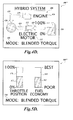
- the exemplary display output 300 may also present the current fuel efficiency (e.g. Miles Per Gallon) relative to the application of the throttle (i.e., accelerator pedal position).
- the display output 300 represents the current MPG graphically with a bar graph 360 that contains visual indicators 362 representing the current MPG. As the vehicle accelerates, visual indicators on the bar graph 360 illuminate or change color to represent the change in fuel efficiency.
- the bar graph 360 graphically depicts ranges of fuel efficiency that are associated with different modes of operation. For example, when the vehicle is operating within the "BEST" range as identified on the bar graph 360 by textual label 364, the vehicle is still in the electric launch mode.
- the display output 300 includes a bar graph 370 that contains visual indicators 372 representing the current application of the throttle.
- the bar graph 370 is associated with numeric representation 374 that represents the percentage that the throttle is applied.
- the bar graphs 360, 370 depict indicators that graphically represent the extent in which application of the throttle will result in a change of fuel efficiency, and in some instances, a change in the mode of operation of the vehicle. While bars are used, other graphical representations may be used to convey such data.
- aspects of the present may provide additional visual, auditory, and/or haptic feedback to convey information regarding whether the current throttle position is in the optimal or preferred range for the current state of operation, or whether the state of operation is about to change, thereby adversely effecting fuel economy.
- the current throttle position e.g., 10%
- the optimal range e.g., all bars are illuminated on graph 360.
- the bar graph 260 may be presented on the graphical display output 300 in a "normal" color (e.g., green).
- FIGURES 4A-4D illustrate other exemplary embodiments of graphical display outputs 400, 400'. 400", 400'" formed in accordance with aspects of the present invention.
- an iconic representation 406 of the vehicle 20 depicts several powertrain components, including an engine icon 410, a motor icon 412, battery icon 414, and wheel icon 420.
- One function of the hybrid information display 92 is to indicate to the vehicle operator which of the various components (e.g., the engine 26, the electric motor generator 28, the energy storage device 38, the vehicle drive wheels 68, etc.) of the hybrid powertrain 22 are currently operating.
- FIGURE 4A illustrates the electric launch mode, in which the energy storage device 38 supplies power to the electric motor generator 28 to provide output torque to the rear wheels 68.
- arrows used as power flow indicators 424 and 426 are selectively displayed between the motor icon 412 and the vehicle drive wheels icon 420 and between the electric motor generator icon 412 and the battery icon 414, to indicate that power is being transferred from the electric motor generator 28 to the vehicle drive wheels 68 and from the energy storage device 38 to the electric motor generator 28.
- the exemplary display 400 may further provide the engine icon 410 and the electric motor generator icon 412 with respective textual labels 430 and 432 that indicate what each icon represents.
- the display output 400 may further include a textual indicator 440, which indicates to the vehicle operator a state of operation of the vehicle 20 that corresponds to the transfer of power between the powertrain components.
- FIGURE 4A the vehicle 20 is in an electric launch mode in which only the electric motor generator 28 contributes to the vehicle drive wheels 68.
- FIGURE 4B is an exemplary graphical display output 400' depicting a regeneration mode, in which torque is transferred from the vehicle drive wheels 68 to the electric motor generator 28, which in turn charges the energy storage device 38.
- the textual indicator 440 indicates a "regeneration” mode.
- FIGURE 4C is an exemplary graphical display output 400" depicting a utility regeneration mode, in which the engine 26 is used to power the electric motor generator 28 as a generator to recharge the energy storage device 38.
- the textual indicator 440 indicates a "utility regeneration" mode.
- FIGURE 4D is an exemplary graphical display output 400'" depicting a "blended torque" mode, in which both the internal combustion engine 26 and the electric motor generator 28 are contributing torque to the vehicle drive wheels 68.
- the display output 400'" includes a third power flow indicator 438 selectively displayed between the engine icon 410 and the wheels icon 420 to indicate that power is being transferred from the internal combustion engine 26 to the real wheels 68.
- FIGURES 5A-5D illustrate other exemplary embodiments of graphical display outputs 500, 500', 500", 500'" formed in accordance with aspects of the present invention.
- the exemplary display output 500' may present the current fuel efficiency (e.g., Miles Per Gallon) relative to the application of the throttle (i.e., accelerator pedal position).
- the display output 500 represents the current MPG graphically with a bar graph 560 that contains visual indicators 562 representing the current MPG. As the vehicle accelerates, visual indicators on the bar graph 560 illuminate or change color to represent the change in fuel efficiency.
- the bar graph 560 graphically depicts ranges of fuel efficiency that are associated with different modes of operation.
- the display output 500 includes a bar graph 570 that contains visual indicators 572 representing the current application of the throttle.
- the display 500 may further include a textual indicator 540, which indicates to the vehicle operator a state of operation of the vehicle 20 (i.e., electric launch mode, regeneration, blended torque, utility regeneration, etc.).
- the bar graphs 560, 570 depict indicators that graphically represent the extent in which application of the throttle will result in a change of fuel efficiency, and in some instances, a change in the mode of operation of the vehicle. While bars are used, other graphical representations may be used to convey such data.
- FIGURE 6 a flow diagram that depicts one exemplary embodiment of a display method 600 formed in accordance with the present invention will be described.
- throttle position information is obtained and displayed relative to fuel efficiency so that a vehicle operator may adjust driving habits to minimize fuel consumption.
- an iconic representation of the vehicle powertrain may be presented.
- the display method 600 may be implemented by the information display module 144 in the information display controller 142 ( FIGURE 1 ). Accordingly, vehicle operational information may be obtained and presented as graphical display outputs 300, 300', 300", 300'", 500, 500', 500", 500'", as described above with reference to FIGURES 3A-3D and 5A-5D .
- the display method 600 begins at block 602, and at block 604, a set of engine operation data is obtained that identifies the present fuel efficiency of the vehicle 20. Other data may be utilized to calculate fuel efficiency, such as transmission output speed, wheel speed, transmission ratio, etc. This data may be transmitted to the information display controller 142 over the CAN 110 where the data is available to the display method 600.
- data is received that includes the current position of the throttle as signaled by the accelerator pedal sensor 110.
- the throttle position data is periodically transmitted over the CAN 112 to the information display controller 142 where it is available to the display method 500.
- the throttle position may be quantified and reported by any number of different vehicle components.
- the throttle position may be reported from the engine controller 114.
- data is received that includes the current operating conditions of the powertrain 22, including the current state or mode of operation.
- the current state or mode of operation data is periodically transmitted over the CAN 112 to the information display controller 142 where it is available to the display method 600.
- this data may be quantified and reported by any number of different vehicle components.
- the current throttle position, the current fuel efficiency, and/or the vehicle state or mode of operation is presented to a vehicle operator.
- the throttle position is presented both numerically and graphically.
- Throttle position data displayed to a vehicle operator on the graphical display output 300 ( FIGURES 3A-3D ), and 500 ( FIGURES 5A-5D ) may be "refreshed" based on the throttle information obtained, at block 606.
- refreshing data that is presented on a graphical display may be performed using techniques that are generally known in the art, these techniques will not be described here.
- the current fuel efficiency data is presented textually and/or graphically.
- Fuel efficiency data displayed to a vehicle operator on the graphical display output 300 ( FIGURES 3A-3D ), and 500 ( FIGURES 5A-5D ) may be "refreshed" based on the throttle information obtained, at block 604.
- refreshing data that is presented on a graphical display may be performed using techniques that are generally known in the art, these techniques will not be described here.
- the state or mode of operation of the vehicle 20 can be presented to the operator in a number of ways.
- an iconic representation of the vehicle and power flow indicators are shown as depicted, for example, in FIGURES 3A-3D and 4A-4D .
- the state or mode of operation can be represented by a textual indicator 340, 540.
- the state of operation data displayed to a vehicle operator on the graphical display output 300 ( FIGURES 3A-3D ), and 500 ( FIGURES 5A-5D ) may be "refreshed" based on the powertrain data, including mode of operation data, obtained, at block 608.
- the method 600 proceeds from block 610 to block 612, where the method 600 ends.
Landscapes
- Physics & Mathematics (AREA)
- General Physics & Mathematics (AREA)
- Engineering & Computer Science (AREA)
- Chemical & Material Sciences (AREA)
- Combustion & Propulsion (AREA)
- Transportation (AREA)
- Mechanical Engineering (AREA)
- Hybrid Electric Vehicles (AREA)
- Electric Propulsion And Braking For Vehicles (AREA)
Applications Claiming Priority (1)
| Application Number | Priority Date | Filing Date | Title |
|---|---|---|---|
| US12/202,114 US20100057281A1 (en) | 2008-08-29 | 2008-08-29 | Information display systems and methods for hybrid vehicles |
Publications (1)
| Publication Number | Publication Date |
|---|---|
| EP2159097A1 true EP2159097A1 (fr) | 2010-03-03 |
Family
ID=41340967
Family Applications (1)
| Application Number | Title | Priority Date | Filing Date |
|---|---|---|---|
| EP09169054A Withdrawn EP2159097A1 (fr) | 2008-08-29 | 2009-08-31 | Système et procédé d'affichage d'informations pour véhicules hybrides |
Country Status (2)
| Country | Link |
|---|---|
| US (1) | US20100057281A1 (fr) |
| EP (1) | EP2159097A1 (fr) |
Cited By (4)
| Publication number | Priority date | Publication date | Assignee | Title |
|---|---|---|---|---|
| JP2014076688A (ja) * | 2012-10-09 | 2014-05-01 | Denso Corp | 車両用表示装置 |
| US8836544B1 (en) * | 2011-02-17 | 2014-09-16 | Brunswick Corporation | Multifunctional displays and display systems for marine vessels |
| FR3013643A1 (fr) * | 2013-11-27 | 2015-05-29 | Technoboost | Dispositif d'affichage pour vehicule hybride qui comprend un moteur a combustion interne et au moins une source de puissance motrice d'hybridation |
| EP3764297A1 (fr) * | 2019-07-08 | 2021-01-13 | Volkswagen Ag | Procédé de fourniture d'une représentation interactive du mode de fonctionnement actuel d'un véhicule |
Families Citing this family (50)
| Publication number | Priority date | Publication date | Assignee | Title |
|---|---|---|---|---|
| US8978798B2 (en) * | 2007-10-12 | 2015-03-17 | Odyne Systems, Llc | Hybrid vehicle drive system and method and idle reduction system and method |
| US8408341B2 (en) | 2007-07-12 | 2013-04-02 | Odyne Systems, Llc | Hybrid vehicle drive system and method and idle reduction system and method |
| US20120207620A1 (en) | 2007-07-12 | 2012-08-16 | Odyne Systems, LLC. | Hybrid vehicle drive system and method and idle reduction system and method |
| JP4530005B2 (ja) * | 2007-07-20 | 2010-08-25 | トヨタ自動車株式会社 | ハイブリッド車両 |
| US8082774B2 (en) * | 2009-02-16 | 2011-12-27 | Ford Global Technologies, Llc | Multi-functional vehicle fuel display |
| US8386104B2 (en) * | 2009-06-01 | 2013-02-26 | Ford Global Technologies, Llc | System and method for displaying power flow in a hybrid vehicle |
| MX2012002959A (es) * | 2009-09-15 | 2012-06-25 | Kpit Cummins Infosystems Ltd | Sistema de impulsion hibrido con requerimiento de potencia reducido para un vehiculo. |
| US8606443B2 (en) | 2009-09-15 | 2013-12-10 | Kpit Cummins Infosystems, Ltd. | Motor assistance for a hybrid vehicle based on user input |
| MX2012002960A (es) * | 2009-09-15 | 2012-06-25 | Kpit Cummins Infosystems Ltd | Sistema de impulsion hibrido para vehiculo teniendo un motor como movedor principal. |
| CN102483020B (zh) | 2009-09-15 | 2015-03-04 | Kpit技术有限责任公司 | 将交通工具转换为混合动力交通工具的方法 |
| US8423214B2 (en) | 2009-09-15 | 2013-04-16 | Kpit Cummins Infosystems, Ltd. | Motor assistance for a hybrid vehicle |
| WO2011039771A2 (fr) | 2009-09-15 | 2011-04-07 | Kpit Cummins Infosystems Ltd. | Assistance moteur pour véhicule hybride sur la base d'une autonomie prédite |
| DE102010005837A1 (de) * | 2010-01-27 | 2011-07-28 | Bayerische Motoren Werke Aktiengesellschaft, 80809 | Verfahren zur Regelung des Ladezustands eines elektrischen Energiespeichers |
| US8786418B2 (en) * | 2010-03-17 | 2014-07-22 | Ford Global Technologies, Llc | Ambient lighting to reflect changes in vehicle operating parameters |
| DE102010041539A1 (de) * | 2010-09-28 | 2012-03-29 | Bayerische Motoren Werke Aktiengesellschaft | Fahrerassistenzsystem zur Unterstützung des Fahrers zum verbrauchskontrollierten Fahren |
| DE102010041544B4 (de) | 2010-09-28 | 2023-05-04 | Bayerische Motoren Werke Aktiengesellschaft | Fahrerassistenzsystem zur Unterstützung des Fahrers zum verbrauchskontrollierten Fahren |
| DE102010041537B4 (de) | 2010-09-28 | 2021-04-15 | Bayerische Motoren Werke Aktiengesellschaft | Fahrerassistenzsystem zur Unterstützung des Fahrers zum verbrauchskontrollierten Fahren |
| US8678116B2 (en) * | 2010-12-31 | 2014-03-25 | Cummins Inc. | Accessory drive configuration |
| US9696176B2 (en) | 2011-01-06 | 2017-07-04 | Ford Global Technologies, Llc | Information display system and method |
| US9613473B2 (en) | 2011-01-06 | 2017-04-04 | Ford Global Technologies, Llc | Method and apparatus for energy usage display |
| US8860565B2 (en) | 2011-01-06 | 2014-10-14 | Ford Global Technlogies, Llc | Information display system and method |
| US9919693B2 (en) * | 2011-01-06 | 2018-03-20 | Ford Global Technologies, Llc | Regenerative braking feedback display and method |
| US20120179395A1 (en) * | 2011-01-06 | 2012-07-12 | Ford Global Technologies, Llc | Information Display System And Method |
| US8903637B2 (en) | 2011-03-24 | 2014-12-02 | GM Global Technology Operations LLC | System and method for calculating an instantaneous fuel economy for a vehicle |
| JP2012244768A (ja) * | 2011-05-19 | 2012-12-10 | Suzuki Motor Corp | 車載充電システム |
| DE102011112707B4 (de) * | 2011-09-07 | 2020-11-05 | Volkswagen Aktiengesellschaft | Anzeigevorrichtung für ein Hybridfahrzeug und Verfahren zur Anzeige und Hybridfahrzeug |
| US20130073129A1 (en) * | 2011-09-21 | 2013-03-21 | Ford Global Technologies, Llc | Vehicle display system and method |
| EP2581268B2 (fr) * | 2011-10-13 | 2019-09-11 | Harman Becker Automotive Systems GmbH | Procédé de contrôle d'un dispositif à sortie optique pour afficher une visualisation panoramique de véhicule et système de visualisation panoramique de véhicule |
| US11225240B2 (en) | 2011-12-02 | 2022-01-18 | Power Technology Holdings, Llc | Hybrid vehicle drive system and method for fuel reduction during idle |
| WO2013113103A1 (fr) | 2012-02-03 | 2013-08-08 | Azure Dynamics, Inc. | Appareil et procédé permettant de distribuer de l'énergie dans un véhicule hybride |
| US11161403B2 (en) | 2012-02-03 | 2021-11-02 | Ge Hybrid Technologies, Llc | Apparatus and method for delivering power in a hybrid vehicle |
| EP2662232A4 (fr) * | 2012-03-09 | 2016-04-27 | Mitsubishi Motors Corp | Dispositif d'affichage des informations véhicule |
| KR20130119771A (ko) * | 2012-04-24 | 2013-11-01 | 현대모비스 주식회사 | 하이브리드 차량에서 동력 흐름을 표시 방법 및 이를 표시하는 장치 |
| KR101354895B1 (ko) * | 2012-06-01 | 2014-01-23 | 엘에스산전 주식회사 | 전력 감시 시스템 및 전력 시스템 정보 디스플레이 방법 |
| US9162566B2 (en) * | 2012-07-24 | 2015-10-20 | Zf Friedrichshafen Ag | PTO with integrated retarder |
| US20140200793A1 (en) * | 2013-01-16 | 2014-07-17 | Toyota Motor Engineering & Manufacturing North America, Inc. | System and method for determining and displaying a fuel-equivalent distance-per-energy consumption rate |
| KR101459953B1 (ko) * | 2013-10-07 | 2014-11-07 | 현대자동차주식회사 | 차량의 주행정보 복원 시스템 |
| DE102013220426B3 (de) * | 2013-10-10 | 2015-03-19 | Continental Automotive Gmbh | Verfahren zum Betreiben eines Fahrzeugs und Fahrerassistenzsystem für ein Fahrzeug |
| CN106061784B (zh) | 2013-11-18 | 2019-07-19 | 电力科技控股有限责任公司 | 采用分轴式动力输出装置的混合动力车辆驱动系统和方法 |
| US20150224979A1 (en) * | 2014-02-07 | 2015-08-13 | GM Global Technology Operations LLC | Drive mode moderator for a vehicle |
| JP6471453B2 (ja) * | 2014-10-22 | 2019-02-20 | 株式会社デンソー | 車両用情報表示装置 |
| DE102015208077A1 (de) * | 2015-04-30 | 2016-11-03 | Deere & Company | Generatoreinheit |
| DE102015214685B4 (de) * | 2015-07-31 | 2017-04-27 | Volkswagen Aktiengesellschaft | Verfahren und System zum Darstellen von Fahrmodi eines Fahrzeugs |
| US10549636B2 (en) | 2017-03-03 | 2020-02-04 | Ford Global Technologies, Llc | Information display systems and method for display an efficiency gauge and target |
| US10781910B2 (en) | 2017-08-03 | 2020-09-22 | Power Technology Holdings Llc | PTO lubrication system for hybrid vehicles |
| BR112020011909A8 (pt) * | 2017-12-15 | 2022-12-06 | Nissan Motor | Método de controle de exibição de economia de combustível e sistema de controle de exibição de economia de combustível |
| CN111479715B (zh) * | 2017-12-15 | 2023-06-27 | 日产自动车株式会社 | 混合动力车辆中的显示方法和显示系统 |
| CN110194183A (zh) * | 2019-05-27 | 2019-09-03 | 中国第一汽车股份有限公司 | 一种双电机混合动力汽车能量流显示方法、显示系统及混合动力汽车 |
| JP2022085672A (ja) * | 2020-11-27 | 2022-06-08 | ヤンマーホールディングス株式会社 | 表示装置および船舶 |
| CN113525656B (zh) * | 2021-07-08 | 2022-10-28 | 哈尔滨工程大学 | 基于螺旋桨转速闭环的气电混合动力船舶能量分配方法 |
Citations (4)
| Publication number | Priority date | Publication date | Assignee | Title |
|---|---|---|---|---|
| US4475380A (en) * | 1982-08-19 | 1984-10-09 | Ford Motor Company | Fuel efficiency monitor |
| US4523457A (en) * | 1982-08-04 | 1985-06-18 | Daimler-Benz Aktiengesellschaft | Rotational speed measuring device with economy field |
| US20050278079A1 (en) | 2004-06-14 | 2005-12-15 | Maguire Joel M | Apparatus and method for displaying graphical information relating to vehicle operation |
| WO2006001809A1 (fr) | 2004-06-30 | 2006-01-05 | Ford Motor Company | Dispositif de presentation d'informations et procede de presentation d'informations pour vehicule |
Family Cites Families (6)
| Publication number | Priority date | Publication date | Assignee | Title |
|---|---|---|---|---|
| US5521824A (en) * | 1992-12-07 | 1996-05-28 | Caterpillar Inc. | Method and apparatus for controlling an engine test apparatus using lead-lag control |
| JP2001154725A (ja) * | 1999-11-30 | 2001-06-08 | Mitsubishi Motors Corp | 車両の故障診断方法及び車両の故障診断装置並びに故障診断用プログラムを記録したコンピュータ読取可能な記録媒体 |
| JP2004312953A (ja) * | 2003-04-10 | 2004-11-04 | Hitachi Ltd | ハイブリッド輸送車両 |
| US7145442B1 (en) * | 2003-10-14 | 2006-12-05 | Yu Hei Sunny Wai | Vehicle operation display system |
| US7474309B2 (en) * | 2003-12-16 | 2009-01-06 | General Motors Corporation | Hybrid vehicle display apparatus and method |
| ITTO20060122A1 (it) * | 2005-02-22 | 2006-08-23 | Honda Motor Co Ltd | Meccanismo di comando e visualizzatore per veicolo ibrido |
-
2008
- 2008-08-29 US US12/202,114 patent/US20100057281A1/en not_active Abandoned
-
2009
- 2009-08-31 EP EP09169054A patent/EP2159097A1/fr not_active Withdrawn
Patent Citations (4)
| Publication number | Priority date | Publication date | Assignee | Title |
|---|---|---|---|---|
| US4523457A (en) * | 1982-08-04 | 1985-06-18 | Daimler-Benz Aktiengesellschaft | Rotational speed measuring device with economy field |
| US4475380A (en) * | 1982-08-19 | 1984-10-09 | Ford Motor Company | Fuel efficiency monitor |
| US20050278079A1 (en) | 2004-06-14 | 2005-12-15 | Maguire Joel M | Apparatus and method for displaying graphical information relating to vehicle operation |
| WO2006001809A1 (fr) | 2004-06-30 | 2006-01-05 | Ford Motor Company | Dispositif de presentation d'informations et procede de presentation d'informations pour vehicule |
Cited By (4)
| Publication number | Priority date | Publication date | Assignee | Title |
|---|---|---|---|---|
| US8836544B1 (en) * | 2011-02-17 | 2014-09-16 | Brunswick Corporation | Multifunctional displays and display systems for marine vessels |
| JP2014076688A (ja) * | 2012-10-09 | 2014-05-01 | Denso Corp | 車両用表示装置 |
| FR3013643A1 (fr) * | 2013-11-27 | 2015-05-29 | Technoboost | Dispositif d'affichage pour vehicule hybride qui comprend un moteur a combustion interne et au moins une source de puissance motrice d'hybridation |
| EP3764297A1 (fr) * | 2019-07-08 | 2021-01-13 | Volkswagen Ag | Procédé de fourniture d'une représentation interactive du mode de fonctionnement actuel d'un véhicule |
Also Published As
| Publication number | Publication date |
|---|---|
| US20100057281A1 (en) | 2010-03-04 |
Similar Documents
| Publication | Publication Date | Title |
|---|---|---|
| US8058982B2 (en) | Information display systems and methods for hybrid vehicles | |
| EP2159097A1 (fr) | Système et procédé d'affichage d'informations pour véhicules hybrides | |
| EP2159096A2 (fr) | Systèmes d'affichage d'informations et procédés pour véhicules hybrides | |
| US9156472B2 (en) | Economic cruise control | |
| US7996125B2 (en) | System and method for displaying vehicle efficiency | |
| EP2159119A1 (fr) | Systèmes et procédés de direction pour véhicules hybrides | |
| US6827167B2 (en) | Hybrid electric vehicle torque distribution | |
| US7898405B2 (en) | Vehicle information display and method | |
| JP4364279B2 (ja) | 車両情報表示装置及び、情報表示方法 | |
| CN104627170B (zh) | 基于负荷的车辆运转控制 | |
| EP2514953B1 (fr) | Dispositif de commande de vehicule | |
| US8718913B2 (en) | Vehicle efficiency information display and method | |
| EP1127730B1 (fr) | Régulation du couple d'un groupe motopropulseur hybride | |
| US9074683B2 (en) | Gear shift indication device | |
| EP2472087B1 (fr) | Dispositif de commande de véhicule | |
| EP0366088B1 (fr) | Système de freinage à récupération d'énergie pour véhicule | |
| US20130190998A1 (en) | Entering and leaving a motor vehicle freewheel running condition with internal combustion engine off | |
| EP0366087B1 (fr) | Système de freinage à récupération d'énergie pour véhicule | |
| CA2722467A1 (fr) | Systeme et procede servant a afficher l'etat d'alimentation d'un vehicule hybride | |
| KR20100125430A (ko) | 전기 견인 시스템 및 방법 | |
| CN104627169B (zh) | 基于负荷的车辆运转控制 | |
| US8527160B2 (en) | Control system and method for automatic selection of a low range gear ratio for a vehicle drivetrain | |
| EP2159091A2 (fr) | Réponse automatique de l'accélérateur pour un véhicule hybride | |
| CN110848380A (zh) | 一种纯电动重型九挡amt变速箱控制系统及控制方法 | |
| CN211315074U (zh) | 一种纯电动重型九挡amt变速箱控制系统 |
Legal Events
| Date | Code | Title | Description |
|---|---|---|---|
| PUAI | Public reference made under article 153(3) epc to a published international application that has entered the european phase |
Free format text: ORIGINAL CODE: 0009012 |
|
| AK | Designated contracting states |
Kind code of ref document: A1 Designated state(s): AT BE BG CH CY CZ DE DK EE ES FI FR GB GR HR HU IE IS IT LI LT LU LV MC MK MT NL NO PL PT RO SE SI SK SM TR |
|
| AX | Request for extension of the european patent |
Extension state: AL BA RS |
|
| 17P | Request for examination filed |
Effective date: 20100830 |
|
| GRAP | Despatch of communication of intention to grant a patent |
Free format text: ORIGINAL CODE: EPIDOSNIGR1 |
|
| RIC1 | Information provided on ipc code assigned before grant |
Ipc: G01D 7/02 20060101ALI20111004BHEP Ipc: B60R 16/023 20060101ALI20111004BHEP Ipc: G07C 5/08 20060101ALI20111004BHEP Ipc: B60K 35/00 20060101AFI20111004BHEP |
|
| STAA | Information on the status of an ep patent application or granted ep patent |
Free format text: STATUS: THE APPLICATION IS DEEMED TO BE WITHDRAWN |
|
| 18D | Application deemed to be withdrawn |
Effective date: 20120306 |