EP2581268B2 - Procédé de contrôle d'un dispositif à sortie optique pour afficher une visualisation panoramique de véhicule et système de visualisation panoramique de véhicule - Google Patents
Procédé de contrôle d'un dispositif à sortie optique pour afficher une visualisation panoramique de véhicule et système de visualisation panoramique de véhicule Download PDFInfo
- Publication number
- EP2581268B2 EP2581268B2 EP11185124.2A EP11185124A EP2581268B2 EP 2581268 B2 EP2581268 B2 EP 2581268B2 EP 11185124 A EP11185124 A EP 11185124A EP 2581268 B2 EP2581268 B2 EP 2581268B2
- Authority
- EP
- European Patent Office
- Prior art keywords
- vehicle
- display control
- control information
- surround view
- vehicle component
- Prior art date
- Legal status (The legal status is an assumption and is not a legal conclusion. Google has not performed a legal analysis and makes no representation as to the accuracy of the status listed.)
- Active
Links
- 238000000034 method Methods 0.000 title claims description 17
- 230000003287 optical effect Effects 0.000 title claims description 14
- 230000008859 change Effects 0.000 claims description 4
- 241001074085 Scophthalmus aquosus Species 0.000 claims description 3
- 230000009471 action Effects 0.000 description 6
- 230000000694 effects Effects 0.000 description 5
- 230000008901 benefit Effects 0.000 description 2
- 239000003086 colorant Substances 0.000 description 2
- 235000004522 Pentaglottis sempervirens Nutrition 0.000 description 1
- 230000006978 adaptation Effects 0.000 description 1
- 238000004040 coloring Methods 0.000 description 1
- 230000007812 deficiency Effects 0.000 description 1
- 230000001419 dependent effect Effects 0.000 description 1
- 238000005286 illumination Methods 0.000 description 1
- 238000012986 modification Methods 0.000 description 1
- 230000004048 modification Effects 0.000 description 1
- 230000008569 process Effects 0.000 description 1
- 230000002062 proliferating effect Effects 0.000 description 1
- 230000003068 static effect Effects 0.000 description 1
- 230000002194 synthesizing effect Effects 0.000 description 1
Images

Classifications
-
- G—PHYSICS
- G06—COMPUTING; CALCULATING OR COUNTING
- G06F—ELECTRIC DIGITAL DATA PROCESSING
- G06F17/00—Digital computing or data processing equipment or methods, specially adapted for specific functions
-
- B—PERFORMING OPERATIONS; TRANSPORTING
- B60—VEHICLES IN GENERAL
- B60R—VEHICLES, VEHICLE FITTINGS, OR VEHICLE PARTS, NOT OTHERWISE PROVIDED FOR
- B60R1/00—Optical viewing arrangements; Real-time viewing arrangements for drivers or passengers using optical image capturing systems, e.g. cameras or video systems specially adapted for use in or on vehicles
- B60R1/20—Real-time viewing arrangements for drivers or passengers using optical image capturing systems, e.g. cameras or video systems specially adapted for use in or on vehicles
- B60R1/22—Real-time viewing arrangements for drivers or passengers using optical image capturing systems, e.g. cameras or video systems specially adapted for use in or on vehicles for viewing an area outside the vehicle, e.g. the exterior of the vehicle
- B60R1/23—Real-time viewing arrangements for drivers or passengers using optical image capturing systems, e.g. cameras or video systems specially adapted for use in or on vehicles for viewing an area outside the vehicle, e.g. the exterior of the vehicle with a predetermined field of view
- B60R1/27—Real-time viewing arrangements for drivers or passengers using optical image capturing systems, e.g. cameras or video systems specially adapted for use in or on vehicles for viewing an area outside the vehicle, e.g. the exterior of the vehicle with a predetermined field of view providing all-round vision, e.g. using omnidirectional cameras
-
- B—PERFORMING OPERATIONS; TRANSPORTING
- B60—VEHICLES IN GENERAL
- B60R—VEHICLES, VEHICLE FITTINGS, OR VEHICLE PARTS, NOT OTHERWISE PROVIDED FOR
- B60R2300/00—Details of viewing arrangements using cameras and displays, specially adapted for use in a vehicle
- B60R2300/60—Details of viewing arrangements using cameras and displays, specially adapted for use in a vehicle characterised by monitoring and displaying vehicle exterior scenes from a transformed perspective
- B60R2300/607—Details of viewing arrangements using cameras and displays, specially adapted for use in a vehicle characterised by monitoring and displaying vehicle exterior scenes from a transformed perspective from a bird's eye viewpoint
-
- B—PERFORMING OPERATIONS; TRANSPORTING
- B60—VEHICLES IN GENERAL
- B60R—VEHICLES, VEHICLE FITTINGS, OR VEHICLE PARTS, NOT OTHERWISE PROVIDED FOR
- B60R2300/00—Details of viewing arrangements using cameras and displays, specially adapted for use in a vehicle
- B60R2300/80—Details of viewing arrangements using cameras and displays, specially adapted for use in a vehicle characterised by the intended use of the viewing arrangement
Definitions
- the invention relates to a method of controlling an optical output device for displaying a vehicle surround view and a vehicle surround view system.
- image sensors In recent years the use of image sensors in vehicles is proliferating. Often, these image sensors/cameras are used in driver assist system in which the image sensors track the vehicle environment, identify objects, and warn the driver of possible dangerous driving situations. Furthermore, image sensors are used as rear view cameras which help the driver with parking the vehicle and which help the driver to be informed of any obstacle located behind the vehicle. The different image sensors provide a three-dimensional scene of the vehicle and its surroundings. An example for such a vehicle surround view system is described in EP 11162470.6 .
- EP 1 094 337 A2 discusses a parking assistance system which comprises a steering angle sensor. A view from above is provided. In the view, a guidance path is provided based on data from the steering angle sensor.
- EP 1 231 110 A2 discloses a picture synthesizing apparatus for superimposing an auxiliary image upon an image converted as if the image were photographed with a virtual viewpoint. A locus line corresponding to the steering wheel angle is provided.
- a camera of a type that applies an overlay to an image and outputs the image with the overlay to an in-vehicle display is provided.
- the overlay shows the projected path of the vehicle based on the current steering wheel angle of the vehicle.
- US 2009/0295922 A1 discloses a vehicle state sensor that detects various states of a vehicle.
- a camera state correction unit calculates the position and posture of a camera of a bird's eye view of the vehicle. These parameters are updated on the basis of a vehicle calculated using the vehicle state sensor.
- US 7 457456 B2 representing the closest prior art discloses an image generating method in which camera information from a plurality of image sensing units is used to generate a surround view of the a vehicle.
- An emergency zone is displayed around the vehicle which is adapted based on an opening or closing state of a vehicle door.
- a method of controlling an optical output device for displaying a vehicle surround view containing a vehicle model comprises determining display control information for at least one vehicle component, and controlling the optical output device to display the vehicle surround view such that the vehicle model is adapted to depict the at least one vehicle component according to the display control information.
- Such display control information contains information on vehicle components, such as wheels, lights or other interior and exterior vehicle components such as the vehicle body or the doors.
- Information on the vehicle components as contained in the display control information may be used to adapt the vehicle model displayed in a vehicle surround view. By this, a more realistic graphical representation of the vehicle is obtained.
- the vehicle components are depicted in the vehicle surround view in a defined manner based on the display control information.
- the vehicle components can be depicted in a way that makes it easier for the user to perceive and understand the vehicle surround view. If the user can intuitively understand the information displayed by the vehicle surround view, it is less likely for the user to be distracted. Dangerous situations due to distraction are less likely.
- the display control information specifies in detail how a certain vehicle component behaves or which properties the vehicle component possesses.
- the display control information may contain information such as colors, velocities, presence or absence of a vehicle component, the operational states of the vehicle components, etc. By providing such information, the vehicle model in the vehicle surround view may be adapted accordingly.
- the display control information of a vehicle window may relate to "fully open window” in order to provide a graphical representation of a fully open window.
- Other possible display control information may relate to "half open window” or “closed window”. It is also possible to specify more precise display control information, relating to such information as “window pane 65% retracted”.
- the status information contains the current operational state of a certain vehicle component, for example the opening state of a door, the turning angle of the steering wheel, or the velocity of the vehicle itself. Many other forms of status information from other vehicle components are possible.
- the status information is updated in accordance with a change in the current operational state of the respective vehicle component. Based on such up-to-date status information of a certain vehicle component, it is possible to determine respective display control information.
- the respective display control information may relate to the vehicle component for which the status information is provided itself, or even to other vehicle components as is explained in detail below.
- this display control information for a vehicle door may contain received status information on the opening state of the door. If the door is wide open, the display control information may indicate "door fully open".
- display control information regarding the wheels of a vehicle may be obtained from status information received from a plurality of other vehicle components. For illustration from the turning angle of the steering wheel, the vehicle velocity, and the diameter of the wheels, display control information of the vehicle wheels regarding the turning angle and the rotational speed may be obtained. Therefore, the display control information of the wheels may be determined from status information obtained from other components of the vehicle.
- a further implementation would be to obtain display control information on whether vehicle lights are switched on or switched off.
- vehicle information is already present on a data bus system contained in the vehicle.
- Certain vehicle components transmit the current operational state from time to time via such a data bus system. It is possible to obtain the status information from the vehicle components via already existing setups within the car.
- sensors may be provided within the seats of a vehicle which indicate whether a vehicle occupant is present in a certain seat.
- the display control information relating to the presence or absence of vehicle components may be determined which represent the form of vehicle occupants.
- the vehicle model of the vehicle surround view may be adapted in order to depict a graphical representation of a vehicle occupant.
- the status information may comprise at least one of the following: wheel rotational speed, steering wheel angle, vehicle velocity, operational state of lights, windowpane position, sunroof position.
- the wheel rotation speed may be obtained directly from a sensor located within the vehicle wheels. If such an information is obtained, it can be used to determine the display control information by specifying a certain rate of rotation which is then used to control the optical output device in order to visualize this rate of rotation of the vehicle in the vehicle model. It is also possible to obtain this information from, for example, the vehicle velocity and a predefined information on the wheel diameter. It is also possible to determine the turning angle of wheels from, for example the steering wheel angle and possibly the vehicle velocity. For illustration, the steering wheel angle may be used to determine a wheel turning angle taking into account the vehicle velocity. Then it is necessary to receive two status information in order to determine the wheel turning angle.
- the operational state of the lights, the window pane position, and the sun roof position can be further used in order to adapt the vehicle model graphically in the vehicle surround view.
- the determining of the display control information over time is reiterated, when a change in status information is detected.
- a change in status information For illustration, when it is detected that a certain vehicle component has a changed operational state, for example the vehicle lights have been switched on by a user or the turn indicators are used, the display control information can be updated accordingly. This results in an update of the graphical representation of the respective vehicle component in the vehicle surround view.
- this has the advantage that when the user performs a certain action, he finds that this action also has some impact on the graphical representation of the vehicle in the vehicle surround view. On the one hand, by this the potential for a dangerous distraction is reduced, because the user can intuitively understand and perceive the depicted vehicle model.
- a higher degree of feedback is provided to the user because a certain action also finds its graphical counterpart in the depiction of the vehicle model in the vehicle surround view.
- Unintended actions of the user may therefore be avoided or limited to a minimum.
- the unintended use of long distance lights may be easily recognized via the vehicle surround view.
- Another advantage is the feedback of actions given to the user.
- a user may switch off the vehicle front lights. When the graphical representation of the front and rear lights of the vehicle are updated so as to represent the operational state of the rear and front lights, a moment of distraction may be avoided which results from the user not perceiving a graphical feedback of his action in the vehicle surround view.
- the display control information is determined based on at least user configuration data obtained from a user input.
- a human interface device which allows a user to adapt certain display control information according to his needs.
- the user may be distracted by a certain appearance of the vehicle model in the vehicle surround view.
- the respective display control information may be adapted such that a vehicle model has a certain vehicle body lacquering, this means the exterior color of the vehicle model may be adapted according to the needs of a user.
- the user configuration data may be stored in a database.
- storing the user configuration data in a database it is possible to maintain a certain appearance of the vehicle model over a period of time. For example, it can be advantageous to set the color of the body of the vehicle model when the car is manufactured via user configuration data. By this, the manufacturer has the possibility to adapt the vehicle model according to the real vehicle parameters.
- the display control information for certain vehicle components such as for those components for which no status information may be received due to the lack of respective sensors, may be predefined. This makes it possible to further adapt the appearance of the vehicle model even though, for example, no status information is received on certain vehicle components such as colors, presence or absence of certain features of the vehicle body, such as a sun roof or rear doors, or optional features purchased by a user. For example, there exists typically no sensor which indicates the presence or absence of a liftback. If the respective display control information is predefined, this has the effect that the appearance of the vehicle model in the vehicle surround view will be adapted accordingly.
- the method according to the currently discussed aspect may further comprise establishing a virtual camera position of the vehicle surround view and calculating a graphical representation of the at least one vehicle component based on the virtual camera position and the display control information.
- the display control information specifies a certain opening angle of a window of the vehicle, e.g. relates to "window pane half retracted”
- a graphical representation of the window in the vehicle model of the vehicle surround view may be calculated by a graphical processor. Because the graphical representation of, for example, a half open window may depend on the camera position used for depicting the vehicle surround view, it may be necessary to interpret the display control information accordingly in order to calculate the graphical representation of the vehicle model which represents this information correctly.
- displaying the vehicle surround view comprises dynamic animation of the at least one vehicle component. For example, it may be possible to animate the turning of the wheels, the flashing of the turn indicators, or the opening and closing of the window pane.
- dynamic animation of the vehicle model the user may more intuitively perceive the vehicle surround view.
- a more realistic vehicle surround view is provided. This is because the dynamically animated vehicle model fits into the dynamic surrounding provided by the vehicle surround view itself. A contrast between the moving background and the static vehicle model is avoided and therefore the potential for dangerous distraction of the user is reduced further.
- the at least one vehicle component is selected from a group comprising: wheel, steering wheel, window pane, front lights, rear lights, sun roof, vehicle body lacquering, turn indicator, or vehicle occupants.
- the adaptation of the vehicle model for those vehicle components has the effect that the vehicle model relates to the vehicle model as perceived by the user in real life.
- the turning angle of the wheels may be adapted according to the current driving situation of the vehicle.
- the background in the vehicle surround view will be moving with respect to the vehicle model.
- the wheels are rotating according to the velocity of the vehicle, the vehicle model and the background obtained from image sensors provide an intuitively perceivable impression on the user.
- a vehicle surround view system comprising a processor for controlling an optical output device for displaying a vehicle surround view containing a vehicle model.
- the processor is configured to determine display control information for at least one vehicle component, and to control the optical output device to display the vehicle surround view such that the vehicle model is adapted to depict the at least one vehicle component according to the display control information.
- Fig. 1 is a schematic view of a vehicle surround view system 3.
- the vehicle surround view system 3 comprises a processor 30.
- the processor 30 is configured to determine display control information for different vehicle components 32, 34.
- it is further configured to control an optical output device 31 in order to adapt a vehicle model contained in a vehicle surround view in order to depict vehicle components 32, 34 based on the respective display control information.
- the optical output device 31 may be a display of a vehicle navigation system or a vehicle computer.
- vehicle navigation systems provide a display which can be used in certain situations to display the vehicle surround view rather than the information on navigation.
- the optical output device is a display only used by the vehicle surround view system itself.
- the display control information is at least partly determined based on status information which is received from either a vehicle component 32 itself or a sensor 33 which detects an operational state of a vehicle component 34.
- a situation where the vehicle component 32 transmits status information directly may be the illumination status of vehicle lights.
- information on the status of vehicle lights, such as "lights on”, “lights off”, or “long distance lights on” are present on a vehicle data bus. Such information may then be directly used in order to determine the respective display control information.
- a sensor 33 may be provided in order to determine a current status of a vehicle component 34. For example, the sensor may be detecting whether at a certain seat a vehicle occupant is present. The sensor 33 may be detecting the opening or closed state of the trunk lid or vehicle door.
- the respective display control information is adapted such that in the vehicle surround view the vehicle door is displayed in the same opening state. It should be understood that it is possible to use status information received from a plurality of vehicle components to determine the display control information for another vehicle component.
- the vehicle surround view system 3 comprises a human interface device 35.
- the human interface device 35 is adapted to allow the user to set display control information via user configuration data.
- the user may specify the color or the absence or presence of certain vehicle components.
- the user may specify a certain appearance of a vehicle occupant.
- the user may provide certain image data such that a vehicle occupant is depicted as a graphical representation familiar to the user.
- the manufacturer of the vehicle can set user configuration data for different vehicle components according to his needs. For example, the manufacturer may specify the user configuration data such that certain features particular to the vehicle are depicted in the vehicle model of the vehicle surround view accordingly.
- Such certain features may be the color of the car, particular shapes of the vehicle body, such as a hatchback or a liftback, presence or absence of a sun roof, or the presence or absence of rear vehicle doors.
- vehicle components it may be difficult to determine display control information based on status information because no accordingly adapted sensor may be present.
- user configuration data is stored in a database 36.
- the database 36 allows to determine display configuration data based on user configuration data, even if no status information is received for the particular vehicle component iteratively over time.
- a graphical processor 37 is adapted to interpret the display control information obtained from processor 30 in order to provide a graphical representation of the vehicle component according to the display control information. This includes determining the viewing angle or other properties of the vehicle surround view in order to calculate the correct graphical representation of the vehicle component. Because there exists typically a large variety of possible graphical representation of a vehicle component in the vehicle model due to the combination between different possible display control information of the vehicle component and different possible viewing angles of the vehicle surround view, it is typically necessary to calculate the graphical representation for each of those combinations within the vehicle surround view system 3 itself. Another possibility is to provide a database of graphical representations relating to certain combinations of display control information and configurations of the vehicle surround views such as the viewing angle. The database contains image data, which is used as a graphical representations of the vehicle component based on the display control information.
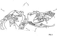
- Fig. 2 is a schematic illustration of a vehicle surround view 1.
- a vehicle model 2 comprising various vehicle components is depicted within a background 4.
- the background 4 is obtained from image sensors which are positioned around the vehicle.
- the background 4 is moving with respect to the vehicle. Therefore, the background 4 constitutes a dynamic surrounding of the vehicle model 2.
- the vehicle model 2 is adapted to dynamically display the properties of the various vehicle components.
- the wheels 10 are displayed in a state where they are rotating as indicated by the arrows in Fig. 2 .
- the displayed representation of the wheels 10 is adapted in order to depict a turning angle.
- the vehicle model 2 is approaching a parking space by turning left. Therefore, in Fig.
- the pair of front wheels are adapted with a turning angle indicating the left turn.
- the front lights 12 are illuminated.
- Front lights 12 are illuminated because the respective display control information indicates that the front lights of the vehicle are illuminated.
- the left turn indicator 13 flashes. This is because the user of the vehicle has switched the turn indicators on, a respective status information has been received, and the respective display control information has been determined accordingly.
- Further vehicle components depicted in Fig. 2 are the sun roof 11, the vehicle occupant 14, the vehicle body lacquering 15, the window pane 16, the steering wheel 17 and the rear lights 18.
- the sun roof 11 is depicted because in the vehicle there is a sun roof 11 present.
- the manufacturer or user may set the respective display control information via user configuration data, such that the sunroof is depicted.
- the display control information relating to sun roof 11 contains information on the opening state of the sun roof 11.
- the sun roof 11 is depicted, based on this display control information, as being half open.
- vehicle occupant 14 is determined to be present via some sensor data provided in the respective seat.
- the display control information indicates the presence of the vehicle occupant and therefore a graphical representation is provided within the vehicle surround view.
- the vehicle occupant is displayed in a user-defined manner.
- the user has provided image data, which allows to generate user configuration data to determine the display control information such that the vehicle occupant 14 is displayed according to the image data.
- Respective operations and configurations apply to the way in which other vehicle components are displayed.
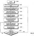
- Fig. 3 shows a flowchart indicating how the vehicle surround view is adapted based on display control information relating to vehicle components.
- the method starts with step 300.
- user configuration data for certain vehicle components is obtained.
- the user configuration data is obtained via some human interface device.
- the user may be provided with a graphical interface allowing him to specify the user configuration data of certain vehicle components.
- vehicle components could be the lacquering of the vehicle body or the color of vehicle interior.
- the user may specify parameters according to his likings.
- the user can personalize certain vehicle components based on the user configuration data. For example, the user can provide some image data for depicting the vehicle occupant according to such image data.
- the user configuration data in step 301 from a database.
- predefined user configuration data is provisioned.
- Such user configuration data may be preset, e.g. by the manufacturer of the vehicle.
- the manufacturer of the vehicle specifies certain user configuration data, such as the coloring of the vehicle body lacquering according to the vehicle body lacquering itself.
- the user configuration data may comprise the presence or absence of certain vehicle components or features thereof. For example, if a certain vehicle comprises a sun roof, the user configuration data indicates the presence of the sun roof.
- vehicle component status information is received.
- the status information comprises information on the operational state of different vehicle components.
- Such a status information may for example indicate the velocity of the vehicle, the turning angle of the steering wheel, the on-/off-state of the vehicle lighting, the opening state of window panes, etc.
- step 303 display control information is determined. For example, from the vehicle velocity and the steering wheel angle, display control information relating to the turning angle of the wheels is determined. From the status information of the window panes, display control information relating to the window panes themselves is determined. Sensor data contained in the status information of certain vehicle components, for example the presence or absence of vehicle occupants or the opening state of the trunk lid, are also used to determine the respective display control information in step 303.
- a virtual camera position of the vehicle surround view is established.
- the virtual camera position may be specified by a user or may be predefined by the system.
- a graphical representation of a vehicle model is calculated.
- the display control information is related to the graphical representation which, in turn, depends on the virtual camera position.
- a window pane is slightly open, depending on the virtual camera position, the window may be displayed differently in the vehicle model. If the virtual camera position is positioned directly above the vehicle, it may be hardly visible in the vehicle surround view that the window pane is open. However, if the virtual camera position is orientated such that the virtual camera faces directly the window pane, the slightly open position of the window pane may be more visible in the graphical representation.
- step 306 image sensor data is obtained and processed. This means that the different images sensors providing the background of the vehicle surround view are read out in order to provide the graphical representation in the vehicle surround view.
- step 307 the vehicle surround view is displayed or the display is refreshed in order to display the newly calculated image data.
- step 308 it is checked whether status information of certain vehicle components has changed. This means, for example, that the status information of a vehicle component has changed by a certain amount which makes it necessary to re-determine the display control information and therefore to update the vehicle model of the vehicle surround view. A threshold comparison of the status information or of the change in status information can be conducted. If it is determined in step 308 that the status information has changed accordingly, the method proceeds with step 302, where the vehicle component status information is newly received and based on this, in step 303, the display control information is newly determined.
- step 308 determines that the status information of a vehicle component has not changed or has changed only slightly. It is sufficient to proceed with step 306, where the image sensor data is obtained anew and processed in order to provide an updated graphical representation of the background.
Claims (7)
- Procédé de commande d'un dispositif de sortie optique (31) pour afficher une vue panoramique de véhicule (1) contenant un modèle de véhicule (2), ledit procédé comprenant :- la réception d'informations de statut sur l'au moins un composant de véhicule indiquant un état opérationnel actuel de l'au moins un composant de véhicule,- la détermination d'informations de commande d'affichage pour au moins un composant de véhicule (10-18),dans lequel les informations de commande d'affichage sont déterminées sur la base d'au moins les informations de statut reçues et des données de configuration utilisateur obtenues à partir d'une entrée utilisateur et qui spécifient en détail comment l'au moins un composant de véhicule se comporte,- l'établissement d'une position de caméra virtuelle de la vue panoramique de véhicule (1),- le calcul d'une représentation graphique de l'au moins un composant de véhicule basée sur la position de caméra virtuelle et les informations de commande d'affichage, dans lequel la représentation graphique est animée dynamiquement en fonction de l'état opérationnel actuel de l'au moins un composant de véhicule indiqué par les informations de commande d'affichage, et- la commande du dispositif de sortie optique (31) pour afficher la vue panoramique de véhicule (1) de sorte que le modèle de véhicule (2) soit adapté pour illustrer l'au moins un composant de véhicule (10-18) animé dynamiquement selon les informations de commande d'affichage.
- Procédé selon la revendication 1, dans lequel les informations de statut comprennent au moins une des suivantes : vitesse de rotation des roues, angle du volant, vitesse du véhicule, état opérationnel des phares, position de la vitre, position du toit ouvrant.
- Procédé selon l'une quelconque des revendications 1 ou 2, dans lequel ladite détermination des informations de commande d'affichage est répétée dans le temps lorsqu'un changement d'informations de statut est détecté.
- Procédé selon la revendication 1, dans lequel les données de configuration utilisateur sont stockées dans une base de données.
- Procédé selon l'une quelconque des revendications précédentes, dans lequel l'au moins un composant de véhicule est sélectionné dans un groupe comprenant : roue (10), volant (17), vitre (16), phares avant (12), phares arrière (18), toit ouvrant (11), vernis de carrosserie (15), clignotant (13), ou occupants du véhicule (14).
- Système de vue panoramique de véhicule (3) comprenant un processeur pour commander un dispositif de sortie optique (31) pour afficher une vue panoramique de véhicule (1) contenant un modèle de véhicule (2), dans lequel ledit processeur est configuré- pour recevoir des informations de statut sur l'au moins un composant de véhicule indiquant un état opérationnel actuel de l'au moins un composant de véhicule,- pour déterminer des informations de commande d'affichage pour au moins un composant de véhicule,dans lequel les informations de commande d'affichage sont déterminées sur la base d'au moins les informations de statut reçues et des données de configuration utilisateur obtenues à partir d'une entrée utilisateur et qui spécifient en détail comment l'au moins un composant de véhicule se comporte,- pour établir une position de caméra virtuelle de la vue panoramique de véhicule (1),- pour calculer une représentation graphique de l'au moins un composant de véhicule basée sur la position de caméra virtuelle et les informations de commande d'affichage, dans lequel la représentation graphique est animée dynamiquement en fonction de l'état opérationnel actuel de l'au moins un composant de véhicule indiqué par les informations de commande d'affichage, et- pour commander le dispositif de sortie optique (31) pour afficher la vue panoramique de véhicule (1) de sorte que le modèle de véhicule (2) soit adapté pour illustrer l'au moins un composant de véhicule animé dynamiquement selon les informations de commande d'affichage.
- Système de vue panoramique de véhicule (3) selon la revendication 6, dans lequel ledit processeur est configuré pour effectuer le procédé selon l'une quelconque des revendications 2 à 5.
Priority Applications (4)
| Application Number | Priority Date | Filing Date | Title |
|---|---|---|---|
| EP11185124.2A EP2581268B2 (fr) | 2011-10-13 | 2011-10-13 | Procédé de contrôle d'un dispositif à sortie optique pour afficher une visualisation panoramique de véhicule et système de visualisation panoramique de véhicule |
| JP2012227095A JP2013089245A (ja) | 2011-10-13 | 2012-10-12 | 車両周囲視野を表示するための光出力デバイスの制御方法および車両周囲視野システム |
| CN201210390188.6A CN103042972B (zh) | 2011-10-13 | 2012-10-15 | 控制显示车辆环景的光学输出装置的方法及车辆环景系统 |
| US13/651,964 US9244884B2 (en) | 2011-10-13 | 2012-10-15 | Method of controlling an optical output device for displaying a vehicle surround view and vehicle surround view system |
Applications Claiming Priority (1)
| Application Number | Priority Date | Filing Date | Title |
|---|---|---|---|
| EP11185124.2A EP2581268B2 (fr) | 2011-10-13 | 2011-10-13 | Procédé de contrôle d'un dispositif à sortie optique pour afficher une visualisation panoramique de véhicule et système de visualisation panoramique de véhicule |
Publications (3)
| Publication Number | Publication Date |
|---|---|
| EP2581268A1 EP2581268A1 (fr) | 2013-04-17 |
| EP2581268B1 EP2581268B1 (fr) | 2016-05-11 |
| EP2581268B2 true EP2581268B2 (fr) | 2019-09-11 |
Family
ID=44799821
Family Applications (1)
| Application Number | Title | Priority Date | Filing Date |
|---|---|---|---|
| EP11185124.2A Active EP2581268B2 (fr) | 2011-10-13 | 2011-10-13 | Procédé de contrôle d'un dispositif à sortie optique pour afficher une visualisation panoramique de véhicule et système de visualisation panoramique de véhicule |
Country Status (4)
| Country | Link |
|---|---|
| US (1) | US9244884B2 (fr) |
| EP (1) | EP2581268B2 (fr) |
| JP (1) | JP2013089245A (fr) |
| CN (1) | CN103042972B (fr) |
Families Citing this family (23)
| Publication number | Priority date | Publication date | Assignee | Title |
|---|---|---|---|---|
| DE102012025317A1 (de) * | 2012-12-22 | 2014-06-26 | Audi Ag | Fahrerassistenzsystem und Verfahren zum Freigeben eines autonomen oder pilotierten Garagenparkens |
| DE102014201801B4 (de) * | 2014-01-31 | 2021-11-25 | Bayerische Motoren Werke Aktiengesellschaft | Verfahren zur perspektivischen Darstellung eines Fahrzeugumfeldes mit einem Fahrzeug-Modell auf einer Fahrzeuganzeige und Anzeigesystem |
| CN104385987B (zh) * | 2014-11-14 | 2017-01-11 | 东风汽车有限公司 | 一种汽车监控方法及系统 |
| US11006095B2 (en) | 2015-07-15 | 2021-05-11 | Fyusion, Inc. | Drone based capture of a multi-view interactive digital media |
| US10222932B2 (en) | 2015-07-15 | 2019-03-05 | Fyusion, Inc. | Virtual reality environment based manipulation of multilayered multi-view interactive digital media representations |
| US10147211B2 (en) | 2015-07-15 | 2018-12-04 | Fyusion, Inc. | Artificially rendering images using viewpoint interpolation and extrapolation |
| US11095869B2 (en) | 2015-09-22 | 2021-08-17 | Fyusion, Inc. | System and method for generating combined embedded multi-view interactive digital media representations |
| US10242474B2 (en) * | 2015-07-15 | 2019-03-26 | Fyusion, Inc. | Artificially rendering images using viewpoint interpolation and extrapolation |
| US11783864B2 (en) | 2015-09-22 | 2023-10-10 | Fyusion, Inc. | Integration of audio into a multi-view interactive digital media representation |
| CN105403415B (zh) * | 2015-12-29 | 2018-01-16 | 腾讯科技(深圳)有限公司 | 一种车辆诊断系统的数据处理方法、装置和系统 |
| US10757375B2 (en) * | 2016-06-02 | 2020-08-25 | Sony Corporation | Display control device and display control method, display device, and moving body device |
| US10678240B2 (en) * | 2016-09-08 | 2020-06-09 | Mentor Graphics Corporation | Sensor modification based on an annotated environmental model |
| CN107878560A (zh) * | 2016-09-30 | 2018-04-06 | 法乐第(北京)网络科技有限公司 | 车轮状态实时显示方法和装置 |
| KR101949438B1 (ko) | 2016-10-05 | 2019-02-19 | 엘지전자 주식회사 | 차량용 디스플레이 장치 및 이를 포함하는 차량 |
| US11202017B2 (en) | 2016-10-06 | 2021-12-14 | Fyusion, Inc. | Live style transfer on a mobile device |
| US10313651B2 (en) | 2017-05-22 | 2019-06-04 | Fyusion, Inc. | Snapshots at predefined intervals or angles |
| US11069147B2 (en) | 2017-06-26 | 2021-07-20 | Fyusion, Inc. | Modification of multi-view interactive digital media representation |
| CN109525790B (zh) * | 2017-09-20 | 2021-06-25 | 杭州海康威视数字技术股份有限公司 | 视频文件生成方法及系统、播放方法及装置 |
| US10592747B2 (en) | 2018-04-26 | 2020-03-17 | Fyusion, Inc. | Method and apparatus for 3-D auto tagging |
| US10694105B1 (en) | 2018-12-24 | 2020-06-23 | Wipro Limited | Method and system for handling occluded regions in image frame to generate a surround view |
| JP7197674B2 (ja) * | 2019-02-27 | 2022-12-27 | 本田技研工業株式会社 | 操舵操作子 |
| JP7318265B2 (ja) * | 2019-03-28 | 2023-08-01 | 株式会社デンソーテン | 画像生成装置および画像生成方法 |
| CN110239437A (zh) * | 2019-05-08 | 2019-09-17 | 北京伏羲车联信息科技有限公司 | 车辆状态呈现方法及装置 |
Citations (4)
| Publication number | Priority date | Publication date | Assignee | Title |
|---|---|---|---|---|
| JPH0399952A (ja) † | 1989-09-12 | 1991-04-25 | Nissan Motor Co Ltd | 車両用周囲状況モニタ |
| US20080129539A1 (en) † | 2006-04-12 | 2008-06-05 | Toyota Jidosha Kabushiki Kaisha | Vehicle surrounding monitoring system and vehicle surrounding monitoring method |
| JP2008152628A (ja) † | 2006-12-19 | 2008-07-03 | Matsushita Electric Ind Co Ltd | 合成映像表示装置 |
| WO2010137684A1 (fr) † | 2009-05-29 | 2010-12-02 | 富士通テン株式会社 | Dispositif de production d'image et système d'affichage d'image |
Family Cites Families (37)
| Publication number | Priority date | Publication date | Assignee | Title |
|---|---|---|---|---|
| US6111582A (en) * | 1996-12-20 | 2000-08-29 | Jenkins; Barry L. | System and method of image generation and encoding using primitive reprojection |
| US7277123B1 (en) * | 1998-10-08 | 2007-10-02 | Matsushita Electric Industrial Co., Ltd. | Driving-operation assist and recording medium |
| US6178358B1 (en) * | 1998-10-27 | 2001-01-23 | Hunter Engineering Company | Three-dimensional virtual view wheel alignment display system |
| DE60009000T2 (de) | 1999-10-21 | 2005-03-10 | Matsushita Electric Industrial Co., Ltd., Kadoma | System zur Einparkhilfe |
| JP3865192B2 (ja) * | 2000-03-31 | 2007-01-10 | 本田技研工業株式会社 | 車両用表示装置 |
| EP1158804A3 (fr) * | 2000-05-24 | 2003-12-17 | Matsushita Electric Industrial Co., Ltd. | Appareil de rendu pour produire une image à afficher |
| EP1167120B1 (fr) * | 2000-06-30 | 2014-08-27 | Panasonic Corporation | Dispositif de rendu pour faciliter le stationnement d'un véhicule |
| US7375728B2 (en) * | 2001-10-01 | 2008-05-20 | University Of Minnesota | Virtual mirror |
| JP3645196B2 (ja) * | 2001-02-09 | 2005-05-11 | 松下電器産業株式会社 | 画像合成装置 |
| WO2004004320A1 (fr) * | 2002-07-01 | 2004-01-08 | The Regents Of The University Of California | Traitement numerique d'images video |
| WO2004015369A2 (fr) * | 2002-08-09 | 2004-02-19 | Intersense, Inc. | Systeme de suivi, d'etalonnage automatique et d'elaboration de plan |
| US6871121B2 (en) * | 2002-10-07 | 2005-03-22 | Blink Engineering Corp. | Entertainment system on-board a vehicle for visualizing on a display real-time vehicle data |
| US7589732B2 (en) * | 2002-11-05 | 2009-09-15 | Autodesk, Inc. | System and method of integrated spatial and temporal navigation |
| US6885939B2 (en) * | 2002-12-31 | 2005-04-26 | Robert Bosch Gmbh | System and method for advanced 3D visualization for mobile navigation units |
| US7619626B2 (en) * | 2003-03-01 | 2009-11-17 | The Boeing Company | Mapping images from one or more sources into an image for display |
| JP2007522981A (ja) * | 2004-02-20 | 2007-08-16 | シャープ株式会社 | 状況検出表示システム、状況検出表示方法、状況検出表示システム制御プログラム、および当該プログラムを記録した記録媒体 |
| JP2005268847A (ja) * | 2004-03-16 | 2005-09-29 | Olympus Corp | 画像生成装置、画像生成方法、および画像生成プログラム |
| US20060155429A1 (en) * | 2004-06-18 | 2006-07-13 | Applied Digital, Inc. | Vehicle entertainment and accessory control system |
| JP2006050263A (ja) | 2004-08-04 | 2006-02-16 | Olympus Corp | 画像生成方法および装置 |
| JP4657765B2 (ja) * | 2005-03-09 | 2011-03-23 | 三菱自動車工業株式会社 | ノーズビューシステム |
| JP4579132B2 (ja) * | 2005-11-01 | 2010-11-10 | アルパイン株式会社 | 車両/周囲画像提供装置 |
| JP5260298B2 (ja) * | 2005-11-11 | 2013-08-14 | フオルクスヴアーゲン アクチエンゲゼルシヤフト | 有利には自動車内に設けられる情報装置と、車両データを通知するための方法、とりわけ車両機能および該車両機能の操作に関する情報を通知するための方法 |
| JPWO2007086431A1 (ja) * | 2006-01-25 | 2009-06-18 | パナソニック株式会社 | 映像表示装置 |
| US9369679B2 (en) * | 2006-11-07 | 2016-06-14 | The Board Of Trustees Of The Leland Stanford Junior University | System and process for projecting location-referenced panoramic images into a 3-D environment model and rendering panoramic images from arbitrary viewpoints within the 3-D environment model |
| JPWO2008126227A1 (ja) * | 2007-03-29 | 2010-07-22 | 富士通マイクロエレクトロニクス株式会社 | 表示制御装置、情報処理装置、および表示制御プログラム |
| JP2009087228A (ja) * | 2007-10-02 | 2009-04-23 | Denso Corp | 画像表示装置 |
| JP5133783B2 (ja) * | 2008-05-30 | 2013-01-30 | アルパイン株式会社 | 車載装置 |
| DE102008034594B4 (de) * | 2008-07-25 | 2021-06-24 | Bayerische Motoren Werke Aktiengesellschaft | Verfahren sowie Informationssystem zur Information eines Insassen eines Fahrzeuges |
| US8188837B2 (en) * | 2008-08-08 | 2012-05-29 | General Motors Llc | Method of finding a key to a mobile vehicle |
| US20100057281A1 (en) * | 2008-08-29 | 2010-03-04 | Paccar Inc | Information display systems and methods for hybrid vehicles |
| US8441441B2 (en) * | 2009-01-06 | 2013-05-14 | Qualcomm Incorporated | User interface for mobile devices |
| WO2010099416A1 (fr) * | 2009-02-27 | 2010-09-02 | Magna Electronics | Système d'alerte pour véhicule |
| US8482486B2 (en) * | 2009-04-02 | 2013-07-09 | GM Global Technology Operations LLC | Rear view mirror on full-windshield head-up display |
| US8378800B2 (en) * | 2009-09-30 | 2013-02-19 | Dei Headquarters, Inc. | Security system and method for operating the same |
| US9150155B2 (en) * | 2010-01-13 | 2015-10-06 | Magna Electronics Inc. | Vehicular camera and method for periodic calibration of vehicular camera |
| JP5302227B2 (ja) * | 2010-01-19 | 2013-10-02 | 富士通テン株式会社 | 画像処理装置、画像処理システム、および、画像処理方法 |
| US8332093B2 (en) * | 2010-05-12 | 2012-12-11 | Toyota Motor Engineering & Manufacturing North America, Inc. | Virtual vehicle interface |
-
2011
- 2011-10-13 EP EP11185124.2A patent/EP2581268B2/fr active Active
-
2012
- 2012-10-12 JP JP2012227095A patent/JP2013089245A/ja active Pending
- 2012-10-15 US US13/651,964 patent/US9244884B2/en active Active
- 2012-10-15 CN CN201210390188.6A patent/CN103042972B/zh active Active
Patent Citations (5)
| Publication number | Priority date | Publication date | Assignee | Title |
|---|---|---|---|---|
| JPH0399952A (ja) † | 1989-09-12 | 1991-04-25 | Nissan Motor Co Ltd | 車両用周囲状況モニタ |
| US20080129539A1 (en) † | 2006-04-12 | 2008-06-05 | Toyota Jidosha Kabushiki Kaisha | Vehicle surrounding monitoring system and vehicle surrounding monitoring method |
| JP2008152628A (ja) † | 2006-12-19 | 2008-07-03 | Matsushita Electric Ind Co Ltd | 合成映像表示装置 |
| WO2010137684A1 (fr) † | 2009-05-29 | 2010-12-02 | 富士通テン株式会社 | Dispositif de production d'image et système d'affichage d'image |
| US20120069187A1 (en) † | 2009-05-29 | 2012-03-22 | Fujitsu Ten Limited | Image generating apparatus and image display system |
Also Published As
| Publication number | Publication date |
|---|---|
| CN103042972A (zh) | 2013-04-17 |
| US9244884B2 (en) | 2016-01-26 |
| US20140107888A1 (en) | 2014-04-17 |
| JP2013089245A (ja) | 2013-05-13 |
| EP2581268A1 (fr) | 2013-04-17 |
| EP2581268B1 (fr) | 2016-05-11 |
| CN103042972B (zh) | 2016-08-03 |
Similar Documents
| Publication | Publication Date | Title |
|---|---|---|
| EP2581268B2 (fr) | Procédé de contrôle d'un dispositif à sortie optique pour afficher une visualisation panoramique de véhicule et système de visualisation panoramique de véhicule | |
| US10766498B2 (en) | Method, apparatus, and computer readable storage medium having instructions for controlling a display of an augmented reality display device for a transportation vehicle | |
| JP6563798B2 (ja) | 視覚認知支援システムおよび視認対象物の検出システム | |
| KR102276096B1 (ko) | 디스플레이 유닛 상에 디스플레이하기 위한 부가 정보의 삽입을 계산하기 위한 방법, 상기 방법을 수행하기 위한 장치 그리고 자동차 및 컴퓨터 프로그램 | |
| US9649936B2 (en) | In-vehicle device, control method of in-vehicle device, and computer-readable storage medium | |
| US9360668B2 (en) | Dynamically calibrated head-up display | |
| US10040350B2 (en) | Control apparatus and related method | |
| US11021103B2 (en) | Method for enriching a field of view of a driver of a transportation vehicle with additional information, device for use in an observer transportation vehicle, device for use in an object, and transportation vehicle | |
| WO2018078732A1 (fr) | Appareil de commande d'affichage, appareil d'affichage et procédé de commande d'affichage | |
| JP2004535971A (ja) | ヘッドアップディスプレイシステム及び方法 | |
| WO2016125042A1 (fr) | Affichages cognitifs | |
| CN111417889A (zh) | 用于在机动车中提供显示的方法以及机动车 | |
| CN113924225A (zh) | 用于通过机动车辆中的驾驶员辅助系统对行驶方向执行修正的方法以及用于此的控制设备 | |
| JP2020526840A (ja) | 道路車両及びマニュアル運転に復帰する方法 | |
| EP3496996A1 (fr) | Procédé pour aider le conducteur d'un véhicule à moteur à manoeuvrer le véhicule à moteur avec une remorque, système d'assistance au conducteur et combinaison véhicule/remorque | |
| US11420680B2 (en) | Method for assisting a user of a motor vehicle when swerving around an obstacle, driver assistance device, and a motor vehicle | |
| EP3885195A1 (fr) | Système et procédé pour fournir un guidage visuel à l'aide de projection de lumière | |
| US11828947B2 (en) | Vehicle and control method thereof | |
| JP6428691B2 (ja) | 車両の室内指標表示装置 | |
| KR102541416B1 (ko) | 실시간 교통정보를 반영한 헤드업 디스플레이 영상 표시 방법 및 장치 | |
| JP2017171117A (ja) | 車両の室内指標表示装置 | |
| KR20230001923A (ko) | 운전자 시선 기반의 헤드업 디스플레이 영상 출력 제어 방법 및 장치 | |
| KR20170065739A (ko) | 헤드업 디스플레이 제어 장치 및 방법 | |
| KR20230129787A (ko) | 실내등 제어시스템 및 이의 제어방법 | |
| JP6288136B2 (ja) | 車両の室内指標表示装置 |
Legal Events
| Date | Code | Title | Description |
|---|---|---|---|
| PUAI | Public reference made under article 153(3) epc to a published international application that has entered the european phase |
Free format text: ORIGINAL CODE: 0009012 |
|
| AK | Designated contracting states |
Kind code of ref document: A1 Designated state(s): AL AT BE BG CH CY CZ DE DK EE ES FI FR GB GR HR HU IE IS IT LI LT LU LV MC MK MT NL NO PL PT RO RS SE SI SK SM TR |
|
| AX | Request for extension of the european patent |
Extension state: BA ME |
|
| 17P | Request for examination filed |
Effective date: 20131007 |
|
| 17Q | First examination report despatched |
Effective date: 20131113 |
|
| GRAP | Despatch of communication of intention to grant a patent |
Free format text: ORIGINAL CODE: EPIDOSNIGR1 |
|
| INTG | Intention to grant announced |
Effective date: 20151203 |
|
| GRAS | Grant fee paid |
Free format text: ORIGINAL CODE: EPIDOSNIGR3 |
|
| GRAA | (expected) grant |
Free format text: ORIGINAL CODE: 0009210 |
|
| AK | Designated contracting states |
Kind code of ref document: B1 Designated state(s): AL AT BE BG CH CY CZ DE DK EE ES FI FR GB GR HR HU IE IS IT LI LT LU LV MC MK MT NL NO PL PT RO RS SE SI SK SM TR |
|
| REG | Reference to a national code |
Ref country code: GB Ref legal event code: FG4D |
|
| REG | Reference to a national code |
Ref country code: CH Ref legal event code: EP |
|
| REG | Reference to a national code |
Ref country code: AT Ref legal event code: REF Ref document number: 798370 Country of ref document: AT Kind code of ref document: T Effective date: 20160515 |
|
| REG | Reference to a national code |
Ref country code: IE Ref legal event code: FG4D |
|
| REG | Reference to a national code |
Ref country code: DE Ref legal event code: R096 Ref document number: 602011026361 Country of ref document: DE |
|
| REG | Reference to a national code |
Ref country code: LT Ref legal event code: MG4D |
|
| REG | Reference to a national code |
Ref country code: NL Ref legal event code: MP Effective date: 20160511 |
|
| REG | Reference to a national code |
Ref country code: FR Ref legal event code: PLFP Year of fee payment: 6 |
|
| PG25 | Lapsed in a contracting state [announced via postgrant information from national office to epo] |
Ref country code: FI Free format text: LAPSE BECAUSE OF FAILURE TO SUBMIT A TRANSLATION OF THE DESCRIPTION OR TO PAY THE FEE WITHIN THE PRESCRIBED TIME-LIMIT Effective date: 20160511 Ref country code: LT Free format text: LAPSE BECAUSE OF FAILURE TO SUBMIT A TRANSLATION OF THE DESCRIPTION OR TO PAY THE FEE WITHIN THE PRESCRIBED TIME-LIMIT Effective date: 20160511 Ref country code: NL Free format text: LAPSE BECAUSE OF FAILURE TO SUBMIT A TRANSLATION OF THE DESCRIPTION OR TO PAY THE FEE WITHIN THE PRESCRIBED TIME-LIMIT Effective date: 20160511 Ref country code: NO Free format text: LAPSE BECAUSE OF FAILURE TO SUBMIT A TRANSLATION OF THE DESCRIPTION OR TO PAY THE FEE WITHIN THE PRESCRIBED TIME-LIMIT Effective date: 20160811 |
|
| REG | Reference to a national code |
Ref country code: AT Ref legal event code: MK05 Ref document number: 798370 Country of ref document: AT Kind code of ref document: T Effective date: 20160511 |
|
| PG25 | Lapsed in a contracting state [announced via postgrant information from national office to epo] |
Ref country code: RS Free format text: LAPSE BECAUSE OF FAILURE TO SUBMIT A TRANSLATION OF THE DESCRIPTION OR TO PAY THE FEE WITHIN THE PRESCRIBED TIME-LIMIT Effective date: 20160511 Ref country code: LV Free format text: LAPSE BECAUSE OF FAILURE TO SUBMIT A TRANSLATION OF THE DESCRIPTION OR TO PAY THE FEE WITHIN THE PRESCRIBED TIME-LIMIT Effective date: 20160511 Ref country code: ES Free format text: LAPSE BECAUSE OF FAILURE TO SUBMIT A TRANSLATION OF THE DESCRIPTION OR TO PAY THE FEE WITHIN THE PRESCRIBED TIME-LIMIT Effective date: 20160511 Ref country code: GR Free format text: LAPSE BECAUSE OF FAILURE TO SUBMIT A TRANSLATION OF THE DESCRIPTION OR TO PAY THE FEE WITHIN THE PRESCRIBED TIME-LIMIT Effective date: 20160812 Ref country code: SE Free format text: LAPSE BECAUSE OF FAILURE TO SUBMIT A TRANSLATION OF THE DESCRIPTION OR TO PAY THE FEE WITHIN THE PRESCRIBED TIME-LIMIT Effective date: 20160511 Ref country code: HR Free format text: LAPSE BECAUSE OF FAILURE TO SUBMIT A TRANSLATION OF THE DESCRIPTION OR TO PAY THE FEE WITHIN THE PRESCRIBED TIME-LIMIT Effective date: 20160511 Ref country code: PT Free format text: LAPSE BECAUSE OF FAILURE TO SUBMIT A TRANSLATION OF THE DESCRIPTION OR TO PAY THE FEE WITHIN THE PRESCRIBED TIME-LIMIT Effective date: 20160912 |
|
| PG25 | Lapsed in a contracting state [announced via postgrant information from national office to epo] |
Ref country code: IT Free format text: LAPSE BECAUSE OF FAILURE TO SUBMIT A TRANSLATION OF THE DESCRIPTION OR TO PAY THE FEE WITHIN THE PRESCRIBED TIME-LIMIT Effective date: 20160511 |
|
| PG25 | Lapsed in a contracting state [announced via postgrant information from national office to epo] |
Ref country code: EE Free format text: LAPSE BECAUSE OF FAILURE TO SUBMIT A TRANSLATION OF THE DESCRIPTION OR TO PAY THE FEE WITHIN THE PRESCRIBED TIME-LIMIT Effective date: 20160511 Ref country code: CZ Free format text: LAPSE BECAUSE OF FAILURE TO SUBMIT A TRANSLATION OF THE DESCRIPTION OR TO PAY THE FEE WITHIN THE PRESCRIBED TIME-LIMIT Effective date: 20160511 Ref country code: SK Free format text: LAPSE BECAUSE OF FAILURE TO SUBMIT A TRANSLATION OF THE DESCRIPTION OR TO PAY THE FEE WITHIN THE PRESCRIBED TIME-LIMIT Effective date: 20160511 Ref country code: DK Free format text: LAPSE BECAUSE OF FAILURE TO SUBMIT A TRANSLATION OF THE DESCRIPTION OR TO PAY THE FEE WITHIN THE PRESCRIBED TIME-LIMIT Effective date: 20160511 Ref country code: RO Free format text: LAPSE BECAUSE OF FAILURE TO SUBMIT A TRANSLATION OF THE DESCRIPTION OR TO PAY THE FEE WITHIN THE PRESCRIBED TIME-LIMIT Effective date: 20160511 |
|
| REG | Reference to a national code |
Ref country code: DE Ref legal event code: R026 Ref document number: 602011026361 Country of ref document: DE |
|
| PLBI | Opposition filed |
Free format text: ORIGINAL CODE: 0009260 |
|
| PG25 | Lapsed in a contracting state [announced via postgrant information from national office to epo] |
Ref country code: AT Free format text: LAPSE BECAUSE OF FAILURE TO SUBMIT A TRANSLATION OF THE DESCRIPTION OR TO PAY THE FEE WITHIN THE PRESCRIBED TIME-LIMIT Effective date: 20160511 Ref country code: SM Free format text: LAPSE BECAUSE OF FAILURE TO SUBMIT A TRANSLATION OF THE DESCRIPTION OR TO PAY THE FEE WITHIN THE PRESCRIBED TIME-LIMIT Effective date: 20160511 Ref country code: PL Free format text: LAPSE BECAUSE OF FAILURE TO SUBMIT A TRANSLATION OF THE DESCRIPTION OR TO PAY THE FEE WITHIN THE PRESCRIBED TIME-LIMIT Effective date: 20160511 Ref country code: BE Free format text: LAPSE BECAUSE OF FAILURE TO SUBMIT A TRANSLATION OF THE DESCRIPTION OR TO PAY THE FEE WITHIN THE PRESCRIBED TIME-LIMIT Effective date: 20160511 |
|
| PLAX | Notice of opposition and request to file observation + time limit sent |
Free format text: ORIGINAL CODE: EPIDOSNOBS2 |
|
| 26 | Opposition filed |
Opponent name: CONNAUGHT ELECTRONICS LTD. Effective date: 20170213 |
|
| PG25 | Lapsed in a contracting state [announced via postgrant information from national office to epo] |
Ref country code: SI Free format text: LAPSE BECAUSE OF FAILURE TO SUBMIT A TRANSLATION OF THE DESCRIPTION OR TO PAY THE FEE WITHIN THE PRESCRIBED TIME-LIMIT Effective date: 20160511 |
|
| REG | Reference to a national code |
Ref country code: CH Ref legal event code: PL |
|
| PG25 | Lapsed in a contracting state [announced via postgrant information from national office to epo] |
Ref country code: MC Free format text: LAPSE BECAUSE OF FAILURE TO SUBMIT A TRANSLATION OF THE DESCRIPTION OR TO PAY THE FEE WITHIN THE PRESCRIBED TIME-LIMIT Effective date: 20160511 |
|
| REG | Reference to a national code |
Ref country code: IE Ref legal event code: MM4A |
|
| PG25 | Lapsed in a contracting state [announced via postgrant information from national office to epo] |
Ref country code: CH Free format text: LAPSE BECAUSE OF NON-PAYMENT OF DUE FEES Effective date: 20161031 Ref country code: LI Free format text: LAPSE BECAUSE OF NON-PAYMENT OF DUE FEES Effective date: 20161031 |
|
| PLBB | Reply of patent proprietor to notice(s) of opposition received |
Free format text: ORIGINAL CODE: EPIDOSNOBS3 |
|
| PG25 | Lapsed in a contracting state [announced via postgrant information from national office to epo] |
Ref country code: LU Free format text: LAPSE BECAUSE OF NON-PAYMENT OF DUE FEES Effective date: 20161013 |
|
| REG | Reference to a national code |
Ref country code: FR Ref legal event code: PLFP Year of fee payment: 7 |
|
| PG25 | Lapsed in a contracting state [announced via postgrant information from national office to epo] |
Ref country code: IE Free format text: LAPSE BECAUSE OF NON-PAYMENT OF DUE FEES Effective date: 20161013 |
|
| PG25 | Lapsed in a contracting state [announced via postgrant information from national office to epo] |
Ref country code: HU Free format text: LAPSE BECAUSE OF FAILURE TO SUBMIT A TRANSLATION OF THE DESCRIPTION OR TO PAY THE FEE WITHIN THE PRESCRIBED TIME-LIMIT; INVALID AB INITIO Effective date: 20111013 Ref country code: CY Free format text: LAPSE BECAUSE OF FAILURE TO SUBMIT A TRANSLATION OF THE DESCRIPTION OR TO PAY THE FEE WITHIN THE PRESCRIBED TIME-LIMIT Effective date: 20160511 |
|
| PG25 | Lapsed in a contracting state [announced via postgrant information from national office to epo] |
Ref country code: MT Free format text: LAPSE BECAUSE OF NON-PAYMENT OF DUE FEES Effective date: 20161031 Ref country code: MK Free format text: LAPSE BECAUSE OF FAILURE TO SUBMIT A TRANSLATION OF THE DESCRIPTION OR TO PAY THE FEE WITHIN THE PRESCRIBED TIME-LIMIT Effective date: 20160511 Ref country code: TR Free format text: LAPSE BECAUSE OF FAILURE TO SUBMIT A TRANSLATION OF THE DESCRIPTION OR TO PAY THE FEE WITHIN THE PRESCRIBED TIME-LIMIT Effective date: 20160511 Ref country code: IS Free format text: LAPSE BECAUSE OF FAILURE TO SUBMIT A TRANSLATION OF THE DESCRIPTION OR TO PAY THE FEE WITHIN THE PRESCRIBED TIME-LIMIT Effective date: 20160511 |
|
| PG25 | Lapsed in a contracting state [announced via postgrant information from national office to epo] |
Ref country code: BG Free format text: LAPSE BECAUSE OF FAILURE TO SUBMIT A TRANSLATION OF THE DESCRIPTION OR TO PAY THE FEE WITHIN THE PRESCRIBED TIME-LIMIT Effective date: 20160511 |
|
| REG | Reference to a national code |
Ref country code: FR Ref legal event code: PLFP Year of fee payment: 8 |
|
| PG25 | Lapsed in a contracting state [announced via postgrant information from national office to epo] |
Ref country code: AL Free format text: LAPSE BECAUSE OF FAILURE TO SUBMIT A TRANSLATION OF THE DESCRIPTION OR TO PAY THE FEE WITHIN THE PRESCRIBED TIME-LIMIT Effective date: 20160511 |
|
| PUAH | Patent maintained in amended form |
Free format text: ORIGINAL CODE: 0009272 |
|
| STAA | Information on the status of an ep patent application or granted ep patent |
Free format text: STATUS: PATENT MAINTAINED AS AMENDED |
|
| 27A | Patent maintained in amended form |
Effective date: 20190911 |
|
| AK | Designated contracting states |
Kind code of ref document: B2 Designated state(s): AL AT BE BG CH CY CZ DE DK EE ES FI FR GB GR HR HU IE IS IT LI LT LU LV MC MK MT NL NO PL PT RO RS SE SI SK SM TR |
|
| REG | Reference to a national code |
Ref country code: DE Ref legal event code: R102 Ref document number: 602011026361 Country of ref document: DE |
|
| PGFP | Annual fee paid to national office [announced via postgrant information from national office to epo] |
Ref country code: FR Payment date: 20190919 Year of fee payment: 9 |
|
| PG25 | Lapsed in a contracting state [announced via postgrant information from national office to epo] |
Ref country code: FR Free format text: LAPSE BECAUSE OF NON-PAYMENT OF DUE FEES Effective date: 20201031 |
|
| P01 | Opt-out of the competence of the unified patent court (upc) registered |
Effective date: 20230526 |
|
| PGFP | Annual fee paid to national office [announced via postgrant information from national office to epo] |
Ref country code: GB Payment date: 20230920 Year of fee payment: 13 |
|
| PGFP | Annual fee paid to national office [announced via postgrant information from national office to epo] |
Ref country code: DE Payment date: 20230920 Year of fee payment: 13 |