EP2156417B1 - Dispositif pour recevoir et émettre des documents de valeur - Google Patents
Dispositif pour recevoir et émettre des documents de valeur Download PDFInfo
- Publication number
- EP2156417B1 EP2156417B1 EP08749304A EP08749304A EP2156417B1 EP 2156417 B1 EP2156417 B1 EP 2156417B1 EP 08749304 A EP08749304 A EP 08749304A EP 08749304 A EP08749304 A EP 08749304A EP 2156417 B1 EP2156417 B1 EP 2156417B1
- Authority
- EP
- European Patent Office
- Prior art keywords
- value
- transport
- documents
- memory
- temporary storage
- Prior art date
- Legal status (The legal status is an assumption and is not a legal conclusion. Google has not performed a legal analysis and makes no representation as to the accuracy of the status listed.)
- Not-in-force
Links
Images


Classifications
-
- B—PERFORMING OPERATIONS; TRANSPORTING
- B65—CONVEYING; PACKING; STORING; HANDLING THIN OR FILAMENTARY MATERIAL
- B65H—HANDLING THIN OR FILAMENTARY MATERIAL, e.g. SHEETS, WEBS, CABLES
- B65H29/00—Delivering or advancing articles from machines; Advancing articles to or into piles
- B65H29/006—Winding articles into rolls
-
- G—PHYSICS
- G07—CHECKING-DEVICES
- G07D—HANDLING OF COINS OR VALUABLE PAPERS, e.g. TESTING, SORTING BY DENOMINATIONS, COUNTING, DISPENSING, CHANGING OR DEPOSITING
- G07D11/00—Devices accepting coins; Devices accepting, dispensing, sorting or counting valuable papers
- G07D11/40—Device architecture, e.g. modular construction
-
- G—PHYSICS
- G07—CHECKING-DEVICES
- G07D—HANDLING OF COINS OR VALUABLE PAPERS, e.g. TESTING, SORTING BY DENOMINATIONS, COUNTING, DISPENSING, CHANGING OR DEPOSITING
- G07D11/00—Devices accepting coins; Devices accepting, dispensing, sorting or counting valuable papers
- G07D11/50—Sorting or counting valuable papers
Definitions
- the present invention relates to a device for accepting and outputting documents of value, in particular banknotes.
- leaf-shaped objects that represent, for example, a monetary value or an authorization and therefore should not be arbitrarily produced by unauthorized persons. They therefore have features which are not easy to manufacture, in particular to be copied, whose presence is an indication of the authenticity, i. the manufacture by an authorized agency.
- Important examples of such value documents are chip cards, coupons, checks, vouchers and in particular banknotes.
- Devices of the above type can be used to pay bills, for example in stores.
- the automated handling of used banknotes, especially those in bad condition, may in such devices lead to malfunctions that have to be eliminated manually by a service person.
- the elimination of such interference may require a considerable amount of time depending on the structure of the device. This has the disadvantage that the device can not be used for payments in the period until the fault is eliminated.
- the maintenance person can manage only a few such devices, which increases the total cost of ownership.
- the banknote sorting apparatus consists of at least three parts, with a centrally located part and at least two parts removable therefrom, which provides easy access to the banknotes Transport system is achieved.
- a banknote system for entering and dispensing banknotes and a method for controlling the banknote system are described.
- a bank note system for entering and dispensing banknotes and a method for controlling a banknote system are provided, with which a plurality of denominations can be processed and which is characterized by a space-saving expansion.
- a space-saving storage of banknotes with different denominations in a simple manner.
- the value of a banknote is determined, so that the nominal value of the deposited banknote is known.
- the determined face value of a banknote is preferably stored in a control unit, so that for each storage unit the order of the deposited banknotes with respect to their face value is known.
- a separate cassette does not have to be provided for each denomination in the banknote system according to the invention.
- a cash dispenser which has an issuing office, at least one storage location at which a trigger device is provided, and a transport device which connects the storage location with the issuing office. Further, in the cash dispenser, a control unit which determines the required number of deduction steps in accordance with a predetermined amount of money, and a check means are provided for detecting the number of bills withdrawn in a deduction step. If too many banknotes are withdrawn from the take-off device of the storage location in a withdrawal step, the test device detects the number of overdrawn banknotes and the control unit reduces accordingly the number of further deduction steps.
- US 5657846 there is described a cash validator transporting a bill to be checked along an enclosed path past a number of sensors for checking the bill.
- the enclosed path is defined between a fixed section of the validator and two hinged sections.
- the two hinged sections of the validator are movable to a maintenance position, thereby clearing the path and allowing access to components in the fixed sections and components in the hinged sections.
- US 2006/0202018 A1 For example, there are described an automated teller machine system and method having cash machines that accept checks and issue cash to users.
- the cash machines are operated to collect image data and magnetic data from checks entered in order to determine the authenticity of the checks and a user's entitlement to receive cash for such checks.
- Cash may be issued by the ATM to the user in exchange for checks entered.
- the ATMs spend cash on communication with a transaction computer.
- the present invention has for its object to provide a device for depositing documents of value, which allows easy elimination of disturbances in at least a portion of the device.
- the device is provided for accepting and outputting value documents of predetermined types. These can be, in particular, vouchers and banknotes. In particular, it may be provided for banknotes of various types, for example predetermined denominations of one or more currencies.
- the components of the device are then designed so that they can process value documents of the given types. Under the pivot axis is understood only a geometric axis.
- the memory device is used to store value documents and, in particular, can also be used to reissue at least one predetermined type of value documents stored in it, i. in particular have at least one recycling memory or input and output memory.
- the input transport device By dividing the input transport device into two parts, of which at least the first part of the input transport device between the operating position, in which a transport of documents of value can take place, and the ⁇ fnungswolf in which the transport path is accessible, about a first pivot axis pivotally supported on the device simple troubleshooting can also be done by less trained personnel.
- the first part may be hinged to the device, so that no parts of the device are removed in a fault elimination.
- a particularly good access to the second part of the input transport device or elements of the second part is advantageously obtained according to a first alternative in that the second part of the input transport means is pivotally supported about a second pivot axis on a stationary portion of the device.
- the second part of the input transport means is pivotally attached to the first part about a second pivot axis. In conjunction with the pivoting of the first part, this can result in a particularly good access to the transport path in the area of the testing device.
- the test device can be held arbitrarily on the device and in particular the input transport device.
- the first part may preferably carry the test device. This can then be swung out of the device.
- the first part may carry a drive device of the input transport device.
- At least one electrical connection of at least one device held in the first part may be configured to a stationary part of the device such that they do not need to be released for pivoting the part.
- This design has the advantage that an opening is made easier for less trained personnel, since electrical connections need not be solved and restored.
- the electrical connection or the electrical connections can be arranged near the pivot axis.
- the transport path can run arbitrarily relative to the direction of the pivoting movement.
- the transport path in the input transport device preferably runs parallel to a plane given by the pivoting movement about the first pivot axis. This has the advantage that the device can be made very narrow ..
- the second part of the input transport device can only have non-driven transport elements. This leads to a particularly simple construction of the device.
- the pivot axes may include any suitable angle, for example a right angle.
- the advantage of a particularly narrow design of the device can be obtained in that the pivot axes are parallel to each other.
- the first part of the input transport device can in principle be held pivotably on the device in different sections.
- a particularly good access can allow an embodiment in which the first part of the input transport device is articulated in the region of the beginning of the transport path to the device. This can then be swung out to a large extent, preferably almost completely out of the device.
- the second part can, as far as provided, also be pivotably mounted or articulated at different locations on the device. If a particularly stable arrangement is to be achieved, the second part of the input transport device can be articulated to the device in the region of the beginning of the transport path. In particular, the first part relative to the device and the second part can then be pivoted relative to the first part in the same direction to open the input transport device.
- the second part of the input transport device can be articulated to the device in the region of the end of the transport path.
- the transport path given by the input transport device can run as desired, but it is essentially designed to be horizontal, that is to say, except for deviations optionally enforced by the geometry of the inspection device.
- the parts in the operating position can be provided in or on the device any suitable locking devices.
- the locking can be done by means of suitable mechanical snap or locking connections, or by means of electrically controllable electromechanical or magnetic elements.
- the transport of value documents from the checking device to the storage device can run as desired, for example by means of a belt transport device.
- the value document transport system is a temporary storage device for occasionally buffering at least two checked value documents that are temporarily stored in the intermediate storage device between at least one assumption layer in the value documents transported by the examination device, and the Store associated storage locations in which at least some of the cached in the temporary storage value documents from the temporary storage device are transportable into the respective memory, is displaceable, and a transport device by means of which the temporary storage device between the acceptance position and the storage locations is movable includes.
- the temporary storage device is used for temporary recording by means of the examination device of checked value documents.
- the examination of the value documents need not be completed during the recording process, but it is sufficient that the testing device has detected at least one property of the value document, which is used to test the value document.
- the evaluation of the detection result can, even after the execution of the test device, also take place during the intermediate storage, but is preferably completed during the intermediate storage.
- the temporary storage device is moved between different coupling layers relative to the checking device and the storage device, in which at least one transport path section of the intermediate storage device is coupled or can be coupled to at least one corresponding transport path section of the storage device or storage device, such that transport from the checking device to the temporary storage device or between the temporary storage device and the storage device is possible.
- the coupling position for the acceptance of value documents from the examination device is the acceptance position, while the coupling layers for the exchange of value documents with the storage device are the storage layers.
- the use of the movable storage device by the temporary storage device allows a very trouble-free transport of the documents of value regardless of their condition, since they, once they have passed trouble-free in the temporary storage device, can be transported over a substantial part of the transport path in this.
- it can be dispensed with a suitable design of the device on switches for distributing the value documents on the memory of the memory device, which further increases the reliability.
- the memory device can in principle have any desired memory. However, since the memory device should also allow re-output of once-accepted value documents as far as possible, preferably at least one of the memories of the memory device is a memory from which value documents can be selectively output.
- At least one of the memories of the memory device can be a memory in which at least two value documents can be stored in an isolated form.
- the one memory may be a winding store. Winding storage have the advantage that they allow a scattered storage of a relatively large number of value documents in a small space and are less prone to failure.
- At least one of the memories of the memory device can be a memory in which value documents can be stored as stacks.
- Such memory are characterized by a particularly high storage capacity based on the space.
- such a memory can be used or formed as an input, output or input / output memory.
- a singler is preferably provided for the memory. The singler may be fixed to the memory or fixed to the device. The latter option allows the use of very simple stacked storage cartridges that are easily replaceable.
- the memory device has at least one output memory from which value documents are only output.
- this can be designed so that from this value documents can only be output during normal operation are.
- Such a memory may in particular be advantageous if banknotes of a particular denomination, for example the smallest denomination of a currency intended for the device, must typically be issued more frequently than they are accepted. A supply of these bills may then be provided which allows operation over an extended period of time before the device no longer contains banknotes of the smallest denomination and may need to be shut down.
- the memory and thus the memory location can be arranged arbitrarily relative to the assumption situation.
- a particularly simple construction results when the at least one assumption layer and the storage layers are located along a linear path.
- the transport device can have a linear guide element, along which the intermediate storage device is movably guided on a linear path between the at least one assumption layer and the storage layers.
- the route along which the intermediate storage device can be moved can in principle be aligned as desired.
- the linear distance with the vertical includes an angle less than 10 °, and most preferably extends substantially vertically.
- the term "vertical” is understood to mean that, in the event that the entire device is arranged horizontally, the vertical direction corresponding to the corresponding direction. runs parallel to the direction of fall.
- the memory of the memory device in the device can be firmly connected to this, so that this at best with tool from the Device can be removed.
- a holding device is provided with at least one receptacle for at least one of the two memories, and the memory is designed as connectable to the respective receptacle and detachable from this module again.
- the holding device has receptacles for all its memory and all memory of the storage device are provided as the respective receptacle connectable and detachable from this module again. In this way, a memory exchange can be done very easily, which facilitates the maintenance of the device.
- a particularly simple interchangeability even for not specially equipped for maintenance personnel results from the fact that the recording and the at least one memory are designed so that the at least one memory tool-free connectable to the respective recording and is detachable from this.
- the memory can for example be hung in the receptacle, - klinkt or snapped.
- a particularly simple and efficient production of the device results when the receptacles of the holding device are of the same design, since then identical memory modules can be used.
- a value document can be transported directly from the intermediate storage device into one of the memories of the storage device.
- the memory device may have a memory transport interface device for at least one of the at least two memories, by means of which a transport of a value document between the respective memory and the temporary memory device can take place.
- an interface device in connection with the transport of value documents hereinafter also referred to simply as an interface, is here and below understood a particular mechanical device that allows a supply or delivery of value documents to or from a device associated with the interface of the device, wherein for supplying or dispensing preferably a complementary Interface is used.
- This design has the advantage that by appropriate design of the interface device, the susceptibility to interference of the transport, in particular from the temporary storage device to the memories of the memory device can be reduced.
- memories that are already available on the market can be used as memory modules, which are designed for other types of valuable document transport.
- corresponding memory transport interfaces are provided for all the memories of the memory device.
- the at least one of the storage transport interface device is provided with a drive so that the storage transport interface device can transport a document of value and not just guide it.
- a particularly simple structure of the device with low susceptibility may result from the fact that memory transport interfaces are provided for the at least two memory and in the device for the memory transport interfaces, a common drive is provided.
- the device may be designed so that a belt-free transport takes place between the intermediate storage device and at least one of the memories. This allows a particularly simple construction of the device.
- the temporary storage device can have one or more arbitrary devices for the temporary storage of value documents, in particular, therefore, allow input and re-output of supplied value documents.
- the temporary storage device may have a temporary storage for at least two value documents which can only be input one after the other into the temporary storage or can be dispensed therefrom.
- the temporary storage may in particular also be a reel storage.
- the buffer in particular also the winding memory on a storage capacity for more than two documents of value, so that an assumption of a larger number of value documents can be done.
- the temporary storage device has a buffer for the occasional intermediate storage of at least two tested value documents.
- the temporary storage device has at least two latches. This allows greater variability in caching.
- one of the latches may be used for temporarily storing a value document for which the test device has acquired measured values, but an evaluation with regard to the denomination, validity or authenticity has still taken place.
- At least one of the at least two latches is preferably a buffer for a single value document.
- At least one of the at least two intermediate stores can store a buffer, in particular a winding storage, be for at least two documents of value, which can be entered only one after the other in the cache or output from this.
- the at least two latches may each be latches for a single value document, into or from which a value document can optionally be input or output.
- the temporary storage device for the temporary storage or each of the temporary storage devices may have a temporary storage transport interface, by means of which a value document can be supplied to the temporary storage device or to the respective intermediate storage devices and / or from the temporary storage device or the respective intermediate storage device Caching is removable.
- This interface which is an interface device as already explained above, can in particular be designed to be complementary to the interface device or the interface devices of the memory device and serves the same purpose.
- the temporary storage device has at least two intermediate storage transport points, a common drive is preferably provided for the temporary storage transport interfaces. This allows a particularly simple construction of the intermediate storage device with reduced mass.
- the transport device and the intermediate storage device preferably have mutually complementary guide elements, by means of which the intermediate storage device guided in process between the coupling layers along a predetermined curve.
- the transport device can in principle have any desired drive elements.
- the following alternative or complementary options are advantageous.
- the transport device together with the temporary storage device can form a linear electric motor.
- This alternative is characterized by the fact that the number of moving parts is particularly low.
- the transport device may comprise a drive device fixed relative to a basic element of the device.
- This embodiment has the advantage that the temporary storage device need not have a drive motor for transport, whereby their mass can be reduced.
- the transport device can in this case in particular comprise a belt connected to the intermediate storage device and / or a chain connected to the intermediate storage device which drives the drive device of the transport device.
- a belt while a toothed belt is preferably used. This embodiment allows a particularly simple construction of the transport device.
- the transport means may include a spindle and drive means for rotating the spindle and the buffer means an element interacting with the spindle, for example a pinion, so that the drive moves the intermediate storage device by turning the spindle.
- This embodiment has the advantage that a very accurate positioning of the temporary storage device is possible.
- the transport device may comprise a drive device connected to the temporary storage device. This option can allow a very simple setup.
- the transport device may in particular have a toothed rack firmly connected to the storage device and the temporary storage device has a pinion engaging in the toothed rack and driven by the drive device.
- the device preferably has an input transport device, by means of which individual value documents can be transported from an input tray by the checking device.
- This input transport device can in principle have any transport elements, for example rollers, rollers, belts, guide elements, and in particular a motor for driving at least one of the transport elements.
- the input transport device can have an input transport interface device, by means of which documents of value transported by the inspection device into the at least one acceptance layer located temporary storage device are transportable.
- This input transport interface may in particular be complementary to the temporary storage transport interface and preferably designed like the storage transport interface devices,
- the testing device can in principle be designed as desired. In particular, it only needs to allow a test during transport in a predetermined transport direction.
- the advantage of a particularly compact and simple structure can be achieved by designing the input transport device and / or the input transport interface device and the test device for bidirectional transport.
- this does not necessarily mean that the test equipment must also allow a test in bidirectional transport.
- This embodiment further offers the advantage that value documents which prove unacceptable in the test need not be output via an output path. Rather, they can be returned to an input tray.
- the device When using the device in a payment device in which deposited banknotes are also used to issue change, the number of accepted banknotes increases more and more.
- the device therefore preferably has a further memory with a storage position assigned thereto, in which value documents can be stored by the intermediate storage device in the corresponding storage position, but are not output from the value documents to the intermediate storage device.
- This memory can be used, in particular, for certain types of documents of value which are generally not intended to be reissued, for example vouchers or banknotes not recognized as genuine.
- the further memory may be arranged in the memory device. Since such documents of value only occur with low frequency in many application situations, the memory, like the recycling memories of the memory device, does not need to be emptied very frequently, so that an arrangement in memory device is favorable.
- such an input memory may be located outside the memory device, preferably within a vault area, separate from a portion of the device in which the memory device is located and serve as a tail memory into which the portion of the input not required for re-issuing change enters authentically recognized value documents, in particular banknotes, are stored and therefore must be emptied more frequently.
- the device When using the device in a payment device, it may often be the case that value documents, in particular banknotes of a certain type, for example a small denomination, are to be issued more frequently than they are accepted.
- the device may preferably have an output memory and / or a receptacle for an output memory, from which value documents can be transported individually to the intermediate storage device.
- the output memory is a stack memory, wherein the stack memory or the recording has a singler. Such stacks allow a particularly space-saving stacking of sheet-shaped documents of value.
- the tested value documents should be further processed depending on the result of the examination of the examination device.
- the checking device can be designed in particular to be able to recognize by means of the checking device according to predetermined criteria whether a value document has one of several predetermined types, for example vouchers or banknotes of predetermined denominations of one or more different predetermined currencies, and if the value document conforms to the criteria is to be treated as valid or real.
- the checking device can have at least one sensor for detecting at least one property of a value document whose signals are used in the testing of the predetermined criteria.
- the testing device can have a suitable signal processing device; but it is possible to use a different signal or data processing device of the device, which is in this respect attributable to the testing device.
- signals are generated which reflect the result of the test, for example the type of the document of value and its validity or authenticity.
- the device then preferably has a control device which activates the transport device as a function of at least the signals of the test device in order to use it to move the buffer device into coupling layers at least partially determined by the signals, in which a transport of a value document from the test device into the buffer device or a transport between the temporary storage device and the storage device can take place.
- the control device can in principle be designed as desired. However, it preferably has at least one processor for executing a computer program and a memory in which a computer program executable by the processor is stored. Instead of a processor, a plurality of parallel or hierarchically coupled processors and / or controllers and / or microprocessors and / or FPGA can be used.
- control device may be designed to control the transport device such that it moves the intermediate storage device into the acceptance position.
- the control device can perform this activation in particular in response to detection signals of a sensor, which detects the supply of a value document to the device.
- the sensor may be a corresponding light barrier.
- control device can be designed to detect by means of the examination device as value documents to be rejected, and to control the transport device upon detection of a value document to be rejected, that the intermediate storage device in which the value document is stored is moved from the acceptance position into an output position the value document can be output to an output device, and the temporary storage device, after reaching the output position, activates the temporary storage device in such a way that it outputs the value document to be rejected.
- control device can be further configured to determine the type and the validity or authenticity of a value document by means of the checking device, to control the intermediate storage device in the assumption position which stores this checked value document, and to store data containing the type and information about the validity or authenticity of the value document and its location in the buffer store play to save. This makes it possible to first accept all means of payment in the form of value documents in order to then carry out the issue of change.
- control device can be designed to control the transport device after the end of a supply of value documents in a storage step depending on the data representing the type and information about the validity or authenticity of cached value documents and their position in the buffer device the temporary storage device is moved in the type of storage locations corresponding to the type of cached value documents, and to control the temporary storage device and the storage device so that the value documents of the type assigned to the storage location are delivered to the storage device.
- a storage of accepted value documents corresponding to the type in particular recognized as genuine notes of the denomination and possibly the type of currency can be made so that they are suitable for issuing change.
- corresponding value document types may be assigned to the memories of the memory device for this purpose, so that the control device makes possible a storage in the memories separated according to type and a corresponding re-output.
- the end of a supply of value documents can be recognized, for example, by the fact that the total value of added value documents exceeds a predetermined amount, for example, a bill amount to be paid or a predetermined part thereof, or that no further value documents are supplied after a predetermined period of time.
- At least two of the memories of the memory device may each be assigned a predetermined type of value documents for disbursement
- the controller may be further configured in a disbursing step in response to a disbursement amount given in the controller and the number and the value in the storage device stored value documents in the form of banknotes of the predetermined type to determine a number and a type of value to be issued from the storage device value documents in the form of banknotes and to control the transport device so that it moves the temporary storage device according to the determined types successively in corresponding storage locations, and the Memory device and the latch device to be controlled so that upon reaching the storage layers, the predetermined number of banknotes of the corresponding type from the storage position in the intermediate Store memory device.
- the amount to be dispensed can in particular be entered into the control device or determined by the latter in dependence on an amount to be paid and the value, if appropriate, of further means of payment supplied to the device.
- control device in each case, if driven interfaces are provided, also control them accordingly.
- control device is preferably further configured to perform the output step before the storing step. This procedure is made possible by the use of a suitable temporary storage device and can significantly shorten the duration of a transaction from deposit of the first value document to the delivery of the last value document to be dispensed.
- the control device is preferably further configured to control the transport device in such a way that it stores the temporary storage device for receiving added value documents first assumption situation, then at least the buffer storage means to control so that the value document in the first, the first acquisition situation corresponding buffer to store, after determining the type, the denomination and the authenticity of the value document, depending on at least the transport means and the buffer storage device to control so that the value document is stored by the first temporary storage in the second temporary storage, or to output to a value document output device.
- the temporary storage device can be used to serve as a holding device in which a value document is held until the result of the examination is present.
- the output of an unacceptable value document can be done easily and quickly in this way.
- the controller may be further configured to not execute a payout and storage step when it has detected the end of a deposit or receives an abort signal that the customer has triggered via an input device of the device. but the transport device controls to move the temporary storage device from the assumption situation in the output position. If the temporary storage device is in this position, it controls it and the value document output device in such a way that the accepted value documents buffered in the temporary storage device are reissued. This has the advantage that a customer can undo an erroneous deposit and get back exactly the value documents paid by him.
- a payment device for paying bills in Fig. 1 in particular, including a device for accepting and issuing value documents, comprises in a housing 10 an invoice reader 12, a coin deposit and withdrawal section 14, a card payment section 16, a value document deposit and withdrawal section 18, and a part of the input and output sections Payout sections representing control device 20 for controlling the bill reader and said sections and for the evaluation of signals of the bill reader and said sections.
- the controller 20 is a part of the input and payout sections according to its function, it is in Fig. 1 shown for clarity only as an independent unit.
- the payment device and in particular the control device 20, are provided so that invoices can be paid by means of different means of payment, with change being returned if necessary.
- the payment device is adapted to a bill supplied by a customer, for example, a printed paper sheet on the data representing the invoice amount, on the invoice amount, for example, in machine-readable form, in the example in the form of a bar code, reproduced by means of for to read the reading of the data of suitable bill reader 12. Thereafter, the payment device accepts one or more payment methods from the customer for payment of the invoice amount.
- the three sections serve 14,16 and 18 in conjunction with the control device 20.
- the controller 20 determines whether the amount paid exceeds the invoice amount and determines if necessary the amount to be returned to the customer exchange money. The controller 20 then controls the coin input and payment section 14 and / or the value document input and output section 18 so that, as far as possible, these documents of value in the form of banknotes and the remaining portion of the non-billable portion of the currency Change amounts, coins are issued to the customer. Thereafter, the payment device may generate and issue a receipt confirming that the amount has been paid, or generating and issuing a signal indicating that the amount has been paid.
- the invoice reader 12, the coin payment and payment section 14, the card payment section 16 and functions corresponding to these components of the control device 20 can be designed in any suitable manner, in particular the person skilled in the known manner.
- the value document importing and disbursing section 18, which is an example of a value document input and output device and a device for accepting and outputting value documents, respectively, is described in a highly schematic manner Fig. 2 is illustrated in more detail.
- the section 18 could be adapted to accept banknotes of different denominations of different currencies.
- it is designed to issue value documents in the form of banknotes.
- a value document output device 24 for collecting and subsequently checking value documents in the form of banknotes and / or vouchers
- a first transport device 28 for transporting a linearly movably guided buffer device 30 to Isolated buffering of at least two checked value documents in the example in the vertical direction
- a memory device 32 more specifically an input and output or recycling memory device provided.
- the recycling memory device 32 is formed to have banknotes therein
- Three different denominations can be stored and reissued separately according to denominations and stored separately from the banknotes vouchers and banknotes not recognized as genuine. Vouchers and banknotes not recognized as real are no longer issued individually during operation.
- Each of the denominations as well as the vouchers and banknotes recognized as not genuine are each assigned an input and output opening or an input opening through which the storage or removal can take place.
- a receptacle 34 for a final memory 36 with an insertable into the receptacle 34 and removable from the receptacle 34 final memory 36 is provided.
- temporary storage device 30 serves to temporarily store or store verified value documents from value document acceptance device 26, to deliver temporarily stored value documents to storage device 32, end storage 36 or value document output device 24, and to temporarily dispense banknotes from storage device 32 and output thereof temporarily stored banknotes to the value document output device 24 and is moved by means of the transport device 28 between corresponding coupling layers, in which a transport of a value document between at least one transport path section of the buffer device 30 and transport path sections of the value document acceptance device 26, the memory device 32, the final memory 36 and / or the value document output device 24 can take place.
- the storage device 32 and the temporary storage device 30 make it possible to transport a final storage location L End , in which value documents from the intermediate storage device 30 can be transported to the final storage 36, and at least one output location L A in which value documents can be transported from the temporary storage device 30 to the value document output device 24.
- the coupling layers are in Fig. 2 represented by dashed representations of the latching means 30 in said layers.
- the operation of the value document acceptance device 26, the transport device 28, the buffer device 30 and the memory device 32 is controlled by signals of the control device 20, which also controls this in response to signals from not described in detail sensors and detectors in these devices, such as those for monitoring Transports, performs.
- the control device 20 in this embodiment comprises a memory 116 and a processor 118 and corresponding data or signal interfaces to the electrical devices of the device.
- the memory 116 instructions of a computer program are stored, in the execution of which the control device controls the respective electrical devices of the device by outputting control signals in such a way that they carry out the method described below.
- a customer enters an invoice receipt in the device from which the controller 20 recognizes by means of the bill reader 12 the amount to be paid. The customer then enters, as already described, means of payment for the payment of the invoice amount.
- a value document is supplied to the value document acceptance device 26, it imports the value document. It outputs a signal to the control device 20, which controls the transport device 28 so that it moves the temporary storage device 30 in the assumption situation L E , unless this already occupies this position.
- the value document acceptance device 26 determines, depending on the embodiment, by means of own evaluation devices and / or using the control device 20, whether the value document is a valid coupon or a banknote recognized as acceptable and genuine according to predetermined audit criteria and what value the value document has.
- the controller 20 detects signals representing the type, the result of the check for authenticity and the value of the value document, and stores the corresponding information.
- the value documents are supplied in this embodiment, after retraction and testing of the temporary storage device 30 in the assumption situation L E and cached in this.
- control device 20 determines that the last-added document of value was recognized as a valid coupon or banknote of a currency acceptable by the device, this stores the value of the document of value and the position in the temporary storage device 30.
- the control device 20 determines that the last-added value document was not recognized as a valid coupon or not as a banknote of a currency accepted by the device, the value acceptance device 26 is activated such that initially no further value documents are accepted. Further, it controls the transport device 28 so that it moves the temporary storage device 30 in the output position LA and outputs the last cached value document on the value document output device 24. Thereafter, the control device 20 controls the transport device 28 to the intermediate storage device 30 to move back into the assumption L E.
- the control device 20 then triggers a collection of another value document which is treated like the preceding one.
- the controller in response to signals from the value document acceptor 26 and the other sections, continuously determines the total value of the funds deposited and compares this with the amount to be paid. If the total value exceeds the amount to be paid, it controls the payment device in such a way that it issues a corresponding indication, for example by means of a display device not shown in the figures, to the customer or depositor and does not accept any further means of payment.
- the controller 20 controls the controller 20 in a storage step, depending on the location and type of cached in the buffer memory 30 value documents, the information about their authenticity and the level of the memory device 32 with respect to the individual denominations the transport device 28 so that they the temporary storage device moves to output the cached value documents into the corresponding coupling layers.
- Valid vouchers and banknotes that are not recognized as genuine are transported into the memory corresponding to the position Ls4 and into which only value documents are entered, while the banknotes of the three denominations recognized as genuine are stored separately according to denominations in the three corresponding recycling bins , Other than real recognized banknotes are stored in the final memory.
- the control is carried out in such a way according to the cached value documents that the transport device 30 the buffer memory means 30 successively in coupling layers according to the order of the value documents in the cache, the type, banknotes in particular the denomination, and banknotes of recognized authenticity of the next from the buffer device 30 at the memory device 32 or, if the denomination of the next value document to be output corresponds to none of the denominations provided for the memory device 32 or the memory device can no longer store another denomination value document, the value memory to be output to the final memory 36 a storage position L corresponding to the type and authenticity of the value document Si or L End moves and the temporary storage device 30 emits the value documents to be output in each case into the storage device 32 or the final storage 36.
- the memory device 28 or, if appropriate, the end memory 36 is correspondingly driven to record the value document and to store it. This completes the storage step.
- the controller 20 determines in the memory device 32 depending on the number and denomination stored banknotes, the invoice amount and the other supplied payment means, which notes are to be returned as change or part of the bill of exchange.
- control device After storing the last banknote to be issued of the change in the temporary storage device 30, the control device controls the transport device 28 such that it moves the temporary storage device 30 into the delivery position L A.
- the temporary storage device 30 controls the temporary storage device 30 and, if appropriate, the value document output device 24 to deliver the cached value documents to the value document output device 24.
- the output of the banknotes then takes place as change or part of the bill of exchange. This ends the output step.
- a second embodiment differs from the first embodiment only by the programming of the control device 20. Otherwise, the device is unchanged, so that the same reference numerals are used and the explanations on the structure in the first embodiment also apply here accordingly.
- control means determines the denomination and number of banknotes to be returned as in the first embodiment and performs the output step, i.
- the transport device 28 controls so that it moves the temporary storage device 30 in the lowest of the storage layers, which are assigned to the denominations of the issued banknotes. It then controls the transport device 28, the storage device 32 and the temporary storage device 30 such that the temporary storage device 30 sequentially stores corresponding storage positions in the individual denominations to be dispensed and corresponding banknotes are stored there from the storage device 32 into the temporary storage device 30.
- the intermediate storage device now contains, in particular, the most recently collected value documents. Upon completion of the output, the controller performs the storage step.
- control device 20 controls, depending on the position and the type of value documents cached in the temporary storage device 30, the information about their authenticity and the level of the Memory device 32 with respect to the individual denominations the transport device 28 so that it moves the temporary storage device for outputting the cached value documents in the corresponding coupling layers.
- the control is carried out as before according to the cached value documents that the transport device 28 the buffer memory 30 successively in coupling layers according to the order of the documents of value in the cache, the type, banknotes in particular the denomination, and banknotes of recognized authenticity of the next from the buffer storage device 30 to the memory device 32 or, if the denomination of the next value document to be output does not correspond to any of the denominations intended for the memory device 32, the value memory to be output to the final memory 36 stores the storage layer L Si or L End corresponding to the type and authenticity of the value document, and the buffer device 30 the value documents to be output in each case into the memory device 32 or the final memory 36.
- the memory device 28 or, if appropriate, the end memory 36 is correspondingly driven to record the value document and to store it.
- FIGS. 3 to 7 a specific, only exemplary embodiment of not part of the control device 20 of the value document input and output section 18 described in the two first embodiments.
- the same reference numerals are used for corresponding devices.
- the part A value document input and output section 18 without the controller 20 will be referred to as a value document module for the sake of convenience.
- the value document acceptance device 26 comprises along an input transport path T E an input pocket 38 for manually inputting individual value documents, a checking device 40 for determining a value of a value document and checking the validity or authenticity of a value document, an optional input transport interface 42 and an input transport device 44 for transport a value document 46 inserted into the input tray 38 passes along or passes through the input transport path on the tester 40 to the input transport interface 42.
- the last input transport path portion T A 'terminating in a coupling end at the input transport interface 42 is substantially horizontal in this example.
- the input tray 38 has a side stop, not shown, on which a customer aligns the value document 46 laterally during insertion and pushes further.
- the input transport device 44 has an input light barrier 47 for detecting a slot of a value document, driven transport rollers 48 and transport belt 50, which transport the value document 46 inserted into the input compartment through the checking device 40, which in this embodiment is designed to recognize banknotes of a predetermined currency and check for authenticity, which are aligned laterally according to the stop.
- the input transport device 44 has two parts 120 and 122, between which the transport path for the documents of value to be transported runs, which in this exemplary embodiment runs substantially horizontally in operation.
- the part 120 has the driven transport elements, in the example the transport rollers 48 and transport belt 50, thus forming a drive part, while the part 122, which is the counterpart to the part 120, more precisely a pressure member and not driven to the driven transport elements , Complementary transport elements 51, in the example pressure rollers and rigid guide elements.
- these parts 120 and 122 are arranged substantially parallel to each other and form between them the transport path for the value documents.
- the entire value document acceptance device 26 is on parallel side elements 124 of the skeleton 22 by means of an at least approximately orthogonal to the transport direction R of the transport path section T A 'and parallel to the determined by the drive and the pressure member 120 and 122 surface of the trans-port path extending Pivot axis 126, which is arranged in the region of the beginning of the transport path, between an operating position in which a value document along the partially enclosed by the parts 120 and 122 transport path to the buffer device 30 in the assumption position is transportable, and an opening position in which a manual Access is possible at least on both ends of the transport path, pivotally articulated.
- the entire value document acceptance device 26, as shown in FIG Fig. 4 shown, swung down.
- the two parts of the input transport means 120 and 122 are pivotally mounted relative to each other, so that by pivoting at least one of the parts relative to the other from an operative position to an open position the transport path T A in the input transport means 44 over an entire length outside the testing device 40 can be exposed.
- the pressure part 122 is hinged to the drive part 120 for this purpose.
- a parallel to the pivot axis 126 extending pivot axis 128 is disposed near the front side of the input conveyor 44 on the drive member 120, so that the pressure member 122 can be pivoted with downwardly pivoted input conveyor 44 upwards.
- a locking of the parts 120 and 122 in the operating position can be done by a corresponding locking device, such as a snap mechanism, not shown.
- the testing device 40 (cf. Fig. 3 ) comprises on the one hand a means for detecting coupons, not shown in the figures, recognizes the coupons, their validity and value determined and outputs corresponding signals to the controller 20, in the example a bar code reader for reading an encrypted bar code and decryption of the represented by the barcode Data representing the value of the voucher.
- the checking device 40 furthermore has a banknote validator 52 for determining the type, in particular the recognition of a predetermined currency and the denomination of banknotes and for checking the authenticity of banknotes according to predetermined criteria. For example, the banknote validator CashRay 90 sold by the applicant can be used.
- the test device 40 then outputs test signals to the control device 20 in accordance with the result of the test, so that it has data which, inter alia, reproduces the type, the validity or the value of the value document.
- the checked value document 46 is then transported to the input transport interface 42, which serves to transfer the value document to the temporary storage device 30 and has a pair of driven rollers 54 for this purpose.
- the location of these rollers defines, at least in part, an acceptance location for the temporary memory device 30 in which it must reside in order to receive a value document output from the input transport interface 42.
- the temporary storage device 30 for occasional intermediate storage of at least two value documents has on a base body 56 via a temporary storage transport interface 58, a downstream buffer memory 60 for receiving, occasional intermediate storage and delivery of isolated value documents via a Transport path section Tz, in the example designed as an exchangeable module winding memory 62, and a fixedly connected to the base 56 motor 64 for operating the winding memory 62th
- the temporary storage transport interface 58 has a pair of transport rollers 66 and a drive device 68 which is coupled to the pair of transport rollers 66 by means of a belt and a gear transmission and which, like the motor 64, is actuated at least indirectly by the control device 20 and is connected to the latter for signal transmission via corresponding devices ,
- the intermediate storage device 30 can be moved between different coupling layers by means of the transport device 28 along a linear direction, which in the example is substantially vertical depending on the inclination of the installation surface of the device (cf. Fig. 6 ).
- the transport device 28 for guiding the temporary storage device 30 along a linear direction via parallel to the base frame 22 fixed guide rails 70 and movable between the guide rails base 56 on both sides via complementary guide means 72, in the example guide carriage, in which the guide rails 70 engage ,
- the transport device 28 optionally has for guidance via a pair of racks 74 mounted in parallel on the skeleton 22, between which the intermediate storage device 30 is movable.
- racks 74 mounted in parallel on the skeleton 22, between which the intermediate storage device 30 is movable.
- complementary gears 76 are arranged on opposite sides of the racks, which engage with the racks 74 and prevent tilting of the latch device 30.
- a drive device connected to the basic structure 22 is provided in this embodiment, which moves the intermediate storage device 30.
- the coupling takes place via a toothed belt transmission.
- a drive means 78 which drives a shaft 80 with a gear pair, and at the other end an axis 82 with a gear pair on the shaft 80 corresponding gear pair.
- To the gear pairs run two endless toothed belts 84 which are fixed to the main body 56 of the latching means 30, so that by movement of the toothed belt 84, the latching means 30 along the skeleton 22 relative to the Werturgianddling issued 26, the Wert collectioniver 24 and in particular the memory means 32 and the end memory 36 is movable up and down.
- the memory device 32 has memory 86, in this embodiment, three recycling memory for receiving, storing and output of value documents, such as winding storage, via an L-shaped retainer 88 for the recycling memory 86 and held on the holding device 88, for each the recycling memory 86 via a storage transport interface 90, by means of which value documents between the respective recycling store and in a suitable coupling position in front of this intermediate storage device 30 back and forth transportable are.
- value documents such as winding storage
- the L-shaped holding device 88 has continuous receiving openings 92 for receiving the recycling storage 86; which are formed in the example by the gap between two mutually parallel L-shaped side walls 94.
- the recycling memories are implemented as tool-free removable and usable modules and in each case by means of first fastening devices, in the example mounting slots 96 in the side walls 94 and the first fastening means complementary first fastening means, in the example pins on the side walls of the recycling memory 86, on the holding device 88 releasably attachable. They can thus be easily exchanged.
- the holder of the recycling memory 86 is designed so that they each with an input / output port 98 for stored or stored documents of value, which is in a at a coupling end to the storage transport interface ending storage transport path section T S , the transport device 28 are facing while insertion or removal of the recycle can take place from the opposite direction.
- the memory transport interfaces 90 arranged in operation between the input-output openings 98 and the transport device 28 each comprise transport elements that are driven together. In the example, it is about a common belt drive 100 driven roller pairs 102, which are in the holding device 86, in the example in the side cheeks 94, stored.
- the storage transport interfaces 90, in the example the pairs of rollers 102 define storage positions which the temporary storage device 30, more precisely the temporary storage transport interface, for the exchange with the respective recycling memory, must assume in order that an exchange of a value document between the temporary storage device 30 and the respective recycling memory can take place.
- the side cheeks 94 are arranged so that the long legs with the mounting slots 96, and thus in particular the memory transport interfaces with their transport device 28 facing opening for documents of value, at least approximately parallel to the possible path of the intermediate storage device 30 are arranged.
- a receptacle 104 for a cassette 106 is optionally provided, which is used for receiving coupons and for receiving banknotes that were classified as non-genuine during the test.
- a memory transport interface is also provided for these, which is designed and arranged corresponding to the other memory transport interfaces of the memory device 32.
- the holding device 88 is further pivotably articulated to a lower, transversely to the direction of travel of the latching device 28 extending edge about an axis extending in the same direction, so that the memory device 32 between an operating position in which the memory transport interfaces are aligned so that a transport to the latching device is possible in one of the storage layers, and an opening position in which the storage transport interfaces are accessible, back and forth swiveled.
- All electrical connections of electrical devices of the memory device 32 for example, not shown electric motors for Drive the recycling memory 86 or the memory transport interfaces 90, to other parts of the device, in particular the control device 20 via a harness, not shown, which leads in the region of the pivot axis of the memory device 32 to the backbone 22.
- This arrangement makes it possible, on the one hand, to be able to easily exchange the recycling memories 86 without having to move further parts as a housing door.
- the holding device 88 with the recycling memories 86 and the cassette 106 ie the storage device 32, can be simply pivoted away from the transport device 28 to eliminate transport disturbances (cf. Fig. 7 ).
- transport disturbances cf. Fig. 7
- all other interfaces for the transfer of value documents between the temporary storage device 30 and the recycling memories 86 or the cassette 104 are therefore directly accessible. In this case, no electrical connections need to be solved, so that the elimination of congestion can be done very easily.
- the receptacle 34 is provided in a vault area 106 for the end storage 36 serving as an end cashier, which likewise has a storage transport interface which likewise defines a storage location and by means of which banknotes can be transported from the temporary storage facility to the end coffers.
- a free-fall cassette is provided as the end memory 36, wherein the receptacle 34 is designed accordingly.
- the safe area 106 is separated from the housing area in which the storage device is arranged, so that access to the safe area can take place independently of the other housing area. Both areas have separate locks, which only with appropriate Keys or permissions can be unlocked. In this way, the final memory can be removed without any manipulation of parts of the device is possible. Conversely, it can be ensured that access to the contents of the vault area is prevented when the device for eliminating disturbances is opened.
- the recycling memory 86, the receptacle 104 and the cassette 106 received therein and the receptacle 34 for the end memory 36 are formed so that the input transport path, the winding memory 62 and said memories or cassettes with their input and / or output openings lie in a plane, ie are not offset from each other.
- the value document output device 24 arranged above the checking device 40 to which value documents from the intermediate storage device via an output transport interface 108 which defines at least one output position of the buffer device 30 is used Caching device can be output.
- this is a simple output device with a bottom 110 and a resilient lid 112, at the end of a pinch roller 114 is formed, provided (see. Fig. 4 ).
- a checking device which is designed to check laterally oriented value documents
- a checking device which checks value documents which are transported centered with respect to the transport path.
- the input conveyor has then preferably via a device for centering the value documents.
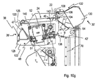
- FIGS. 8 to 11 Another embodiment is in the FIGS. 8 to 11 shown. It differs from the first embodiment by the formation of the temporary storage device, the formation of the input transport device, the arrangement of the recycling memory in the storage device and a corresponding change of the control device.
- the same reference numerals are used and the explanations and variants of the preceding embodiments are also applicable here.
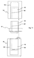
- Fig. 8a and 8b For the sake of clarity, the value document input and payment section 18 ', which is shown only very schematically, now has an intermediate storage device 30' (cf. Fig. 9 ) having two latches 130 and 132 and corresponding buffer transport interfaces 134 and 136.
- the buffer 132 is a buffer for a single value document and the buffer 130 is a buffer, in particular a coil, for at least two value documents that can be entered only occasionally successively in the buffer 130 or output from this.
- the transport device 28 moves the temporary storage device 30 'to use the intermediate storage device 130 together with the temporary storage transport interface 134 in the acquisition position L E1 or to use the intermediate storage device 134 together with the temporary storage transport interface 136 in FIG the assumption situation L E2 .
- the transport device 28 moves the temporary storage device 30 'to use the intermediate storage device 130 together with the temporary storage transport interface 134 in the acquisition position L E1 or to use the intermediate storage device 134 together with the temporary storage transport interface 136 in FIG the assumption situation L E2 .
- the transport device 28 moves the temporary storage device 30 'to use the intermediate storage device 130 together with the temporary storage transport interface 134 in the acquisition position L E1 or to use the intermediate storage device 134 together with the temporary storage transport interface 136 in FIG the assumption situation L E2 .
- the buffer 130 may be formed as a reel as in the first embodiment, while the second buffer memory 132 is a memory for a single document of value, in the example a repository on the buffer 130.
- the intermediate transport interfaces 134 and 136 are constructed the same. Further, they are driven by a common drive means 138 of the latching means 30 ', wherein also embodiments with a separate drive are conceivable.
- the intermediate memory 132 embodied as a single memory is designed so that it can store all value-document types permissible for the payment, in particular those having the greatest extent transversely to the transport direction.
- the buffer memory 130 only has to be designed to hold the value documents which are stored in the memory device.
- the input conveyor 44 ' is opposite the input conveyor 44 changed in two ways.
- the input transport device 44 '(cf. Fig. 10a ) via a modified input transport interface 42 'and via a first transport drive device 140, which drives the transport elements of the input transport device 44', which is unchanged except for the drive and the input transport interface 42 'with respect to the input transport device 44, and a second transport drive device 142 which controls the input transport interface 42'. drives.
- the second transport drive device 142 connected to and controlled by the modified control device 20 'for signal transmission is designed so that it can transport a value document to or from the intermediate storage device 30' in the holding region 146 in response to signals from the control device 20 '
- This embodiment the position of the switch 144 by a not shown, by the control device 20 'controlled point machine is changeable.
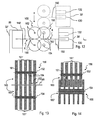
- the memory device 32 'differs from the memory device 32 only thereby; in that at least one of the recycling memories 86, namely that for the banknotes of the smallest extent transverse to the transport direction, relative to the buffer 130 of the buffer device 30 'is arranged in the corresponding storage position such that the center of stored banknotes transversely to the transport direction is in or the recycling memory is offset relative to the center of banknotes of the same type stored in the buffer 130.
- the offset is selected so that, when temporarily storing banknotes in the buffer 130 in which the banknotes are aligned with a predetermined edge parallel to the transport direction, and transferring the banknote of the type specified for the recycling store 86 to the recycling store, the distance of the center of the banknote in the buffer from the center in the recycling store of stored banknotes of the same type is reduced.
- the recycling memories 86 are all offset by the same amount in the same direction.
- the offset of the recycling memory 86 depending on the banknote types to be stored in these, for example denominations of banknotes of the same currency, may each be selected differently.
- FIG. 11 illustrates in the banknotes 166, 166 'of two different widths in the transport path from the inspection device 40 via the transport interfaces to the winding storage 130 of the buffer device 30' in the assumption layer L A1 with solid lines; IM in the winding storage 130 and in one of the recycling winding storage 86, which is drawn in the figure for the sake of clarity along the transport direction R shown in dashed lines. Due to the orientation of the banknotes along their longitudinal edge, they pass into the winding store 130 in which they are likewise stored aligned along their longitudinal edge. As a result, they are arranged asymmetrically in the winding 168. With only a few notes, the storage is not affected.
- the controller 20 is modified from the controller 20 to drive means of the value document input and output section by outputting control signals so as to perform the following procedure.
- euro banknotes are used as banknotes in denominations of 5 euros, 10 euros, 20 euros, 50 euros, 100 euros, 200 euros and 500 euros.
- the first five denominations each have different latitudes and longitudes increasing with denomination, the last three different lengths increasing with denomination, but equal widths.
- the recycling storage 86 serve to receive banknotes of the three denominations 5 euros, 10 euros and 20 euros.
- a payment can be made as follows (see also Fig. 10a to g ): A customer enters an invoice receipt into the device, from which the control device 20 'recognizes the amount to be paid by means of the invoice reader 12. The customer then enters, as already described, means of payment for the payment of the invoice amount.
- the processing of entered value documents should be described in more detail.
- a value document is supplied to the value-document acceptance device 26 ', it imports the value-document by means of the first transport-drive device 140. It outputs a signal to the control device 20 'which controls the transport device 28 so that it moves the temporary storage device 30' into the assumption position L E2 , provided that it is not already in this position. This is the assumption situation in which the entry transport interface 42 'faces the second staging transport interface 136, so that a value document can be stored in the staging memory 132.
- the control device 20 ' now controls the second transport drive device 142, if necessary, the switch 144 and the buffer device 30', in this example, the drive device 138 and thus the latch storage interface 136 so that the value document is transported through the interfaces in the buffer memory 132 , wherein in this embodiment, the rear end of the value document seen in the transport direction remains trapped in the buffer storage interface 136.
- the staging transport interface 136 may be considered part of the cache 132.
- the value document acceptance device 26 determines meanwhile, depending on the embodiment by means of own evaluation devices and / or using the control device 20 ', if the value document is a valid voucher or according to predetermined examination criteria as a banknote of a valid currency and recognized as real banknote and what value the value document Has. Further, the controller 20 'determines, based on signals from the validator 40, whether the value document has been skewed for further processing.
- control means 20 reads in signals representing the type, the result of the authenticity check and the value, and stores the corresponding data.
- the value acceptor 26 is actuated so that initially no further Value documents are accepted.
- the transport device 28 is driven so that it moves the latching means 30 'in the discharge position L A2 (see. Fig. 10b ) in which the staging transport interface 136 opposes the input of the value document output device 24, so that the value document can be output from the intermediate memory 132 to the value document output device 24.
- the buffer means 30 ' in this example, the drive means 138, so controlled that the cached value document is output from the buffer memory 132 to the value document output device 24, by means of which then a return to the Customers done. Thereafter, the control device 20 'controls the transport device 28 to move the temporary storage device 30' back to the acceptance position L E2 .
- control device 20 determines that the last-added document of value has been recognized as a valid coupon or banknote of a currency acceptable by the device, it compares, in the presence of a recognized banknote, as to whether its recognized value is greater than the largest denomination of the banknote banknotes to be stored in the storage device 28 ', and / or whether the storage device 28' can no longer store banknotes of this denomination.
- control device 20 controls the transport device 28 such that it moves the temporary storage device 30' into the final storage location L End2 , in which a value document stored in the temporary storage 130 can be transported into the final storage device 36 (cf. Fig. 10c ).
- the control device 20 performs a restoring of the value document from the intermediate memory 132 into the temporary memory 130 (cf. Fig. 10d to 10e ).
- the control device 20 controls the intermediate storage device 30', in this example the drive device 138, and the input transport interface 42 ', in this example the second transport drive device 142 and, if necessary, the switch 144 or its drive, the value document is output from the intermediate memory 132 into the holding region 146, wherein the rear edge of the value document in the transport direction remains clamped in the input transport interface 42 '(cf. Fig. 10d ).
- the controller 20 drives the conveyor 28 so in that the intermediate storage device 30 'moves into the acceptance position L E1 , in which a value document can be transported through the input transport interface 42' into the temporary storage device 130.
- the control device 20 'then stores data about the value of the value document, the type of the value document, information about the recognized authenticity of the value document and the position of the value document in the buffer device 30', in the example the buffer 130.
- controller 20 'initiates further retraction of another value document treated like the previous one.
- control means 20 in response to signals from the value document acceptor 26 and the other sections, continuously determines the total value of the funds deposited and compares this with the amount to be paid. If the total value exceeds the amount to be paid, it controls the payment device in such a way that it issues a corresponding indication, for example by means of a display device, not shown in the figures, to the depositor and does not accept any further means of payment.
- the control device 20 'then executes a storage step in which the assumed cached value documents in the storage device and / or the final memory are stored.
- the control device 20 ' depending on the location and the type of cached in the latch device 30' value documents and the level of the memory device 32, the transport device 28 so that these successively according to the type, in banknotes in particular the denomination of the next from the temporary storage means 30 'to the storage means 32' or the final storage 36 -aus hybrid value document anometer to a corresponding storage position and in this the next value document to the memory device 32 'or, if the memory device 32' is filled with notes of the denomination of the banknote to be dispensed to the end memory 36 emits.
- the memory device 32 'or the end memory 36 is driven accordingly to record the value document and to save.
- the storing step is ended when the accepted value documents stored in the temporary storage device 30 ', more specifically the temporary storage 130, are stored in the storage device 32' or the final storage 36.
- control means 20 determines which bills to return as change or part of the change, depending on the number and denomination of notes stored in the storage means 32', the amount invoiced and the other currency supplied.
- control device 20 ' In an output step, the control device 20 ', starting with the denomination stored in the memory device 32' at the bottom, then controls the transport device 28, the storage device 32 'and the buffer device 30' such that the buffer device 30 'successively in the individual denominations to be issued corresponding storage locations are moved and there corresponding banknotes from the memory device 32 'in the buffer memory 30', more precisely, the buffer 130, are stored.
- the control device 20' controls the transport device 28 such that it moves the temporary storage device 30 'into the delivery position L A1 , in which value documents can be output from the temporary storage 130 to the value document issuing device 26 ,
- the first temporary storage transport interface 134 and the output transport interface 108 are opposite each other.
- the temporary storage device 30 ' controls the temporary storage device 30 ', more precisely the drive device of the intermediate storage device 130 and the drive device 138 (cf. Fig. 10g ) to deliver the cached value documents to the value document output device 24.
- the output of the banknotes then takes place as change or part of the change. This ends the output step.
- transport device 28 moves to corresponding signals of the control device 20 'the temporary storage device 30' in the assumption L E2 .
- the issue of the bill of exchange in analogy to the second example of the method described above takes place before the storage of the accepted value documents in the storage device 32 'or the end memory 36.
- the steps of the method until the end of the deposit are the same as in the variant described immediately above. The last of these steps is that, when the total value exceeds the amount to be paid, the controller 20 'controls the payment device so that it outputs a corresponding indication, for example by means of a display device not shown in the figures, to the depositor and no further Accepts payment.
- the controller 20 ' determines which bills to return as change or part of the bill, depending on the number and denomination of bills stored in the storage means 32', the bill amount and the other currency supplied.
- the denomination stored in the memory device 32 'at the bottom it then controls the transport device 28, the memory device 32' and the buffer device 30 'such that the buffer device 30' successively moves respective storage layers into the individual denominations to be output and there corresponding banknotes from the memory device 32 'in the latch memory 30', more precisely, the latch 130, are stored (see. Fig. 10g ).
- the control device 20' controls the transport device 28 such that it moves the temporary storage device 30 'into the delivery position L A1 , in which value documents can be output from the temporary storage 130 to the value document issuing device 26 ,
- the first temporary storage transport interface 134 and the output transport interface 108 are opposite each other.
- it controls the temporary storage device 30 ', more precisely the drive device of the intermediate storage device 130 and the drive device 138 (cf. Fig. 10g ) to deliver the cached value documents to the value document output device 24.
- the output of the banknotes then takes place as change or part of the change.
- the intermediate storage device 30 ' more precisely the temporary storage 130, there are now only the paid-in value documents provided for storage in the storage device 32' and the final storage 36.
- the control device 20 ' controls the transport device 28 in such a way that they successively correspond to the value Type, in denomination banknotes, the value document to be output next from the temporary memory device 30 'to the memory device 32' or the final memory 36 moves to a corresponding storage position and into this the respective next document of value to the memory device 32 'or if the memory device 32' is filled with notes of the denomination of the banknote to be dispensed to the final memory 36.
- the memory device 32 'or the end memory 36 is driven accordingly to record the value document and to save.
- transport device 28 moves to corresponding signals of the control device 20 'the temporary storage device 30' in the assumption L E2 .
- a particularly favorable embodiment of the interfaces of the device which is also an example of a device for handling documents of value, is disclosed in US Pat Fig. 12 to 15 using the example of one of the recycling memories 86 of the memory device 32 as the first device, which has a transport path section 148 along which a value document is transported from the first device, and the buffers 130 and 132 as second devices which have a transport path section 150 along which a value document is transported to and / or out of the second devices.
- the first device could also be provided by the input transport device 44 ', the transport path section being the transport path section T A ' and the pair of rollers representing the input transport interface 42 '.
- the transport device 28 represents a movement device, by means of which the second transport path sections 150 along a predetermined curve, here the substantially vertically extending, given by the guide rails 70 trajectory of the buffer device 30 'relative to the memory device 32' and the memory 86 and thus the first transport path section 148 is movable so that in at least one coupling position of the devices to each other, namely in the case that the temporary storage device occupies one of the assumption, a document of value from the transport path portion 148 of the first device in the assumption position corresponding transport path section of the second device is transportable.
- the curved section extends in a plane given by the curved section and the transport direction R in the transport path sections.
- the axes of rotation 152 and 154 are therefore aligned parallel to each other.
- the projecting portions 162 of the circumference of the rollers of a pair constitute the document-carrying and clamping portions and do not engage the recessed groove-like portions 164 of the rollers, so that the document of value is not deformed (see FIG. FIGS. 12 and 13 ).
- the pairs of rollers 156 and 158 are now arranged and designed such that on the one hand in the respective receiving position corresponding rollers 160 and 160 'of the pairs of rollers 156 and 158 intermeshing intermesh (see. FIGS. 12 and 14 ).
- the intermediate storage device 30 'and thus the pairs of rollers 158 move in or out of the receiving position, they are guided past one another in a meshing manner (cf. FIGS. 12 and 14 ).
- the identically formed rollers of the roller pairs 158 also have a comb-like profile, but may differ from that of the other roles, so that a Kämm can be achieved (see. Fig. 14 ). Again, the prominent areas of the roles face each other.
- the input transport interface 44 ', the other storage transport interfaces 90 and the output transport interface 108 are formed except for the drive as the storage transport interface 90 and aligned in the direction of travel of the latch 33' and thus the second transport path sections 150 so that the recessed areas are aligned in this direction, so that the pairs of rollers 158 are intermeshed by the pairs of rollers of the input transport, storage transport and output transport interfaces in processes of the buffer device 30 '.
- the interfaces differ in the nature of their drive.
- a common drive means is provided for the storage transport interfaces, which coupled to the driven rollers via a belt.
- the input transport and output transport interfaces each have their own drive device, in the case of the input transport device a stepper motor.
- staging transport interfaces 134 and 136 have common drive means, at the staging storage transport interface 136 both rollers are mechanically coupled by gears, while at the staging transport interface 134 only the upper roller is driven.
- this distance d is about 1 mm.
- the rollers comprise in this embodiment, in each case a plurality of identically formed wheels 161 ', which are held on a rotatably mounted shaft 161 or axis at the same distance from each other.
- the wheels each form the protruding areas.
- the outer diameter of the rollers is chosen between 13 mm and 25 mm and in this example is 16 mm.
- At least the protruding surface areas of the rollers, in particular the driven rollers, are made of an elastic material, in the example of a resilient polymeric material, which deforms somewhat as a document of value passes through the roller pair.
- This configuration of the transport interfaces or transport interface devices is advantageous for all transport interfaces or interface devices of the devices of the exemplary embodiments, in particular, the acceptance, buffer, storage and output transport interface.
- Variants of the embodiments described above differ by the design of the memory device 32 or 32 'and the training, in the example programming the control device 20 or 20'. All other properties are unchanged, so that the reference numerals and the explanations apply accordingly here.
- the memory device 32 "differs from those of the previous embodiments in that it has a further receptacle 170 for an output memory for dispensing individual banknotes, which has a stacking cassette 172 for a larger storage capacity and compared to the capacity of the recycling memories 86 a singler 174 for separating the value documents from the stacking cassette.
- This stacking cassette can serve as a pure output memory for banknotes of one of the denominations which are also used in the recycling memories 86 are stored.
- this banknote can store particularly frequently paid-out denominations or banknotes of the smallest denomination.
- a memory transport interface 176 is again arranged.
- the control device is now compared with the control devices of the preceding embodiments in that it takes into account the number and denomination of the banknotes stored in the output memory in determining the type and the number of banknotes to be issued, and controls the transport device to determine whether it is withdrawn the determined number of banknotes of the smallest denomination from the corresponding memory 86 falls below a minimum fill level of this memory. It controls in the output step, the memory device and the temporary storage device then so that they remove only as many banknotes from the memory 86 in the corresponding storage location, that the minimum level is not exceeded. It also controls the transport device to move the temporary storage device in a corresponding coupling position in front of the storage transport interface for the output memory. It then controls the output memory, the corresponding memory and buffer transport interface and the buffer device so that the still needed number of banknotes to be issued is stored from the payout memory into the buffer device. The following sub-steps of the output step remain unchanged.
- the electrical connections run as in the first embodiment, so that opening can be done without disconnecting the electrical connections.
- FIG. 17 differs from the first embodiment only in that the second portion 214 of the input conveyor now at the front in the transport direction end of the first part 210 of the input transport device containing the testing device and the driven parts, and about a geometric pivot axis 212 between an operating and an opening position is pivotally hinged. As a result, the second part 214 can be pivoted downwards in the open position relative to the first part. All other devices are unchanged, so that the same reference numerals are used for them and the explanations to this also apply accordingly.
- FIG. 18 differs from the last embodiment only in that the first part 210 'and the second part 214' of the input transport device in each case at the front end in the transport direction is pivotable about a common geometric pivot axis 212 'between an operating and an open position hinged. As a result, the second part 214 'can be pivoted down in the open position relative to the first part. All other facilities are unchanged, so that the same reference numerals are used for these and the explanations to this also apply accordingly.
- At least one of the recycling memories is a stack with a singler.
- the singler can be part of the stack or part of the storage device.
- Such memories make it possible to store a particularly large number of value documents or banknotes. It is possible, for example, only run the recycling memory for the lowest denomination as a stack, since the largest output requirement is expected for this denomination.
- the alignment can thereby, depending on the design of the examination device, consist in a centering of the banknotes or a lateral orientation.
- the input tray is designed as an input tray for a pile of banknotes, which is followed by a singler for separating an inserted banknote stack.
- the value document output device is designed as an output device for output of value documents as a clamped bundle or loose bundle.
- end memory 36 is not a free-fall cassette but a stamped cassette or a safety bag and the device accordingly has a modified receptacle for these final memory types.
- Still other embodiments differ from the previously described embodiments solely in that no vouchers are processed, and that accordingly the test device has no corresponding device and the programming of the control device is changed accordingly.
- the value document output device 24 may also be arranged below the examination device.
- control device is modified.
- the modification consists in that, when the control device has detected the end of a deposit or receives a cancellation signal that the customer has triggered via an input device of the device, does not perform a payout and storage step but rather drives the transport device, the buffer device is made to move the assumption situation into the Ausgabelage. If the temporary storage device is in this position, it controls it and the value document output direction such that the accepted value documents buffered in the temporary storage device are reissued.
Claims (18)
- Procédé de réception et de délivrance de documents de valeur (46) comprenant
un équipement de vérification (40) pour la vérification de l'authenticité de documents de valeur (46) introduits,
un équipement de transport d'entrée (44; 44') pour le transport de documents de valeur le long d'un chemin de transport (TA) passant près de l'équipement de vérification (40) ou à travers ce dernier, et qui comporte une première et une seconde partie (120, 122; 210, 214; 210; 214'),
un équipement de stockage (32) qui comprend au moins deux réservoirs (86) pour le stockage d'au moins deux différents types de documents de valeur, de telle sorte qu'un document de valeur de chacun des deux types est optionnellement délivrable à partir de l'équipement de stockage (32) indépendamment de l'ordre dans lequel eut lieu l'entrée de documents de valeur dans l'équipement de stockage (32),
ainsi qu'un système de transport de documents de valeur (28, 30) pour le transport de documents de valeur vérifiés à l'équipement de stockage (32) ou de ce dernier à un équipement de délivrance de documents de valeur (24),
au moins la première partie (120; 210) de l'équipement de transport d'entrée (44; 44') étant maintenue au dispositif de manière pivotable autour d'un premier axe de pivotement (126; 212), entre une position de fonctionnement dans laquelle un transport de documents de valeur peut avoir lieu et une position d'ouverture dans laquelle le chemin de transport (TA) est accessible,
la première et la seconde partie (120, 122, 210, 214, 214') de l'équipement de transport d'entrée (44; 44') se faisant face lors du fonctionnement et formant entre elles le chemin de transport (TA), caractérisé en ce que la seconde partie (122) de l'équipement de transport d'entrée (44) est maintenue à une section stationnaire (124) du dispositif de manière pivotable autour d'un second axe de pivotement ou en ce que la seconde partie (122, 214, 214') de l'équipement de transport d'entrée (44; 44') est fixée à la première partie (120; 210; 210') de manière pivotable autour d'un second axe de pivotement (128; 212; 212'). - Dispositif selon la revendication 1, dans lequel la première partie (120; 210) supporte l'équipement de vérification (40).
- Dispositif selon la revendication 1 ou 2, dans lequel la première partie (120; 210) supporte un équipement d'entraînement (120) de l'équipement de transport d'entrée (44; 44').
- Dispositif selon une des revendications précédentes, dans lequel au moins une connexion électrique d'au moins un équipement tenu dans la première partie (120, 210), de préférence les connexions électriques de tous les équipements électriques tenus dans la première partie (120, 210) appartenant à une partie stationnaire du dispositif sont réalisées de telle manière que ces dernières n'ont pas besoin d'être détachées pour le pivotement de la partie (120, 210).
- Dispositif selon une des revendications précédentes, dans lequel le chemin de transport (TA) dans l'équipement de transport d'entrée (44, 44') a un tracé parallèle à un plan donné par le mouvement de pivotement autour du premier axe de pivotement (126, 212).
- Dispositif selon une des revendications précédentes, dans lequel la seconde partie (122; 214; 214') de l'équipement de transport d'entrée (44, 44') ne comporte que des éléments de transport non entraînés.
- Dispositif selon une des revendications précédentes, dans lequel les axes de pivotement (126, 128; 210, 212; 210, 212') ont un tracé parallèle l'un à l'autre.
- Dispositif selon une des revendications précédentes, dans lequel la première partie (120) de l'équipement de transport d'entrée (44; 44') est articulée au dispositif dans la zone du début du chemin de transport (TA).
- Dispositif selon une des revendications précédentes, dans lequel la seconde partie (122) de l'équipement de transport d'entrée (44; 44') est fixée à la première partie (120) de manière pivotable autour d'un second axe de pivotement (128) et dans lequel la seconde partie (122) de l'équipement de transport d'entrée (44; 44') est articulée au dispositif dans la zone du début du chemin de transport (TA).
- Dispositif selon une des revendications précédentes, dans lequel la seconde partie (214; 214') de l'équipement de transport d'entrée (44') est fixée à la première partie (210) de manière pivotable autour d'un second axe de pivotement (212') et dans lequel la seconde partie (214; 214') de l'équipement de transport d'entrée (44') est articulée au dispositif dans la zone de la fin du chemin de transport.
- Dispositif selon une des revendications précédentes, dans lequel le système de transport de documents de valeur (28, 30) comprend un équipement de stockage temporaire (30) pour le stockage temporaire sous forme déliassée d'au moins deux documents de valeur vérifiés qui est déplaçable entre au moins une position de réception dans laquelle des documents de valeur acheminés par l'équipement de vérification (40) sont temporairement stockables dans l'équipement de stockage temporaire (30) et des positions de stockage affectées aux réservoirs (86) dans lesquelles au moins quelques uns des documents de valeur temporairement stockés dans l'équipement de stockage temporaire (30) sont transportables à partir de l'équipement de stockage temporaire (30) jusque dans le réservoir respectif, et un équipement de transport (28) au moyen duquel l'équipement de stockage temporaire (30) peut être mû entre la position de réception et les positions de stockage.
- Dispositif selon la revendication 11, dans lequel au moins un des réservoirs (86) de l'équipement de stockage (32) est un réservoir à partir duquel des documents de valeur sont délivrables sous forme déliassée et qui est de préférence un réservoir à enroulement.
- Dispositif selon la revendication 11 ou 12, dans lequel au moins un des réservoirs (86) est un réservoir dans lequel au moins deux documents de valeur sont stockables sous forme déliassée et qui est de préférence un réservoir à enroulement.
- Dispositif selon une des revendications de 11 à 13, dans lequel l'équipement de stockage (32) comporte au moins un réservoir de délivrance (106) à partir duquel des documents de valeur ne sont que délivrés.
- Dispositif selon une des revendications de 11 à 14, dans lequel les au moins deux réservoirs (86) sont agencés de telle façon que la au moins une position de réception et les positions de stockage se trouvent le long d'un parcours linéaire, et dans lequel le parcours linéaire a de préférence essentiellement un tracé vertical.
- Dispositif selon une des revendications de 11 à 15, dans lequel un dispositif de maintien (88) comportant au moins un logement de réception (92) pour au moins un des deux réservoirs (86) est prévu, et le réservoir est prévu en tant que module rattachable au logement de réception respectif et enlevable à nouveau de ce dernier, et
dans lequel le logement de réception (92) et le réservoir sont de préférence réalisés de telle manière que c'est sans nécessiter d'outil que le réservoir peut être rattaché aux logements de réception (92) respectif ou en être enlevé. - Dispositif selon une des revendications de 11 à 16, dans lequel l'équipement de stockage temporaire (30) dispose d'un réservoir intermédiaire (30) pour au moins deux documents de valeur qui ne peuvent être que l'un après l'autre introduits dans le réservoir intermédiaire (30) ou délivrés à partir de ce dernier, et en ce que le réservoir intermédiaire (30) est de préférence un réservoir à enroulement.
- Dispositif selon une des revendications de 11 à 17, comportant un équipement de commande (20) qui, en fonction au moins des signaux de l'équipement de vérification (40), commande le dispositif de transport (28, 30) pour, au moyen de ce dernier, conduire l'équipement de réservoir intermédiaire (30) dans une position déterminée au moins partiellement par les signaux.
Applications Claiming Priority (2)
| Application Number | Priority Date | Filing Date | Title |
|---|---|---|---|
| DE102007020752A DE102007020752A1 (de) | 2007-05-03 | 2007-05-03 | Vorrichtung zur Annahme und zur Ausgabe von Wertdokumenten |
| PCT/EP2008/003562 WO2008135244A2 (fr) | 2007-05-03 | 2008-05-02 | Dispositif pour recevoir et émettre des documents de valeur |
Publications (2)
| Publication Number | Publication Date |
|---|---|
| EP2156417A2 EP2156417A2 (fr) | 2010-02-24 |
| EP2156417B1 true EP2156417B1 (fr) | 2013-01-16 |
Family
ID=39791121
Family Applications (1)
| Application Number | Title | Priority Date | Filing Date |
|---|---|---|---|
| EP08749304A Not-in-force EP2156417B1 (fr) | 2007-05-03 | 2008-05-02 | Dispositif pour recevoir et émettre des documents de valeur |
Country Status (5)
| Country | Link |
|---|---|
| US (1) | US8172066B2 (fr) |
| EP (1) | EP2156417B1 (fr) |
| CA (1) | CA2684704A1 (fr) |
| DE (1) | DE102007020752A1 (fr) |
| WO (1) | WO2008135244A2 (fr) |
Family Cites Families (22)
| Publication number | Priority date | Publication date | Assignee | Title |
|---|---|---|---|---|
| DE2506195B2 (de) * | 1974-02-22 | 1976-11-25 | Glory Kogyo KJC., Himeji, Hyogo (Japan) | Geraet zum ausgeben von aus banknoten zusammengestellten geldbetraegen |
| KR940011424B1 (ko) * | 1985-06-17 | 1994-12-15 | 가부시기가이샤 히다찌세이사꾸쇼 | 지폐류의 취급장치 및 그 취급방법 |
| DE4005291C2 (de) * | 1989-02-22 | 1995-06-29 | Nsm Ag | Einrichtung für die Prüfung und Speicherung von Banknoten bei einem selbstkassierenden Automaten |
| US6311819B1 (en) * | 1996-05-29 | 2001-11-06 | Cummins-Allison Corp. | Method and apparatus for document processing |
| KR970007741B1 (ko) * | 1993-03-31 | 1997-05-16 | 가부시끼가이샤 니뽄곤락스 | 지폐처리장치 |
| GB9319180D0 (en) * | 1993-09-16 | 1993-11-03 | Ncr Int Inc | Automated financial system |
| US5657846A (en) * | 1995-07-13 | 1997-08-19 | Cashcode Company Inc. | Currency validator with split housing |
| JP3336210B2 (ja) * | 1996-02-29 | 2002-10-21 | ローレルバンクマシン株式会社 | 紙幣処理機 |
| US7753189B2 (en) * | 2003-08-01 | 2010-07-13 | Cummins-Allison Corp. | Currency processing device, method and system |
| WO1999010847A1 (fr) * | 1997-08-27 | 1999-03-04 | Siemens Nixdorf Informationssysteme Ag | Distributeur automatique d'argent |
| DE19958017B4 (de) * | 1999-12-02 | 2013-08-14 | Giesecke & Devrient Gmbh | Vorrichtung zum Sortieren von Banknoten |
| JP4038321B2 (ja) * | 2000-02-25 | 2008-01-23 | 株式会社日本コンラックス | 紙幣処理装置 |
| GB2360385B (en) * | 2000-03-16 | 2003-11-05 | Mars Inc | Multi-denominational currency store |
| CA2357930A1 (fr) * | 2001-09-28 | 2003-03-28 | Cashcode Company Inc. | Accumulateur de billets de banque |
| JP4166133B2 (ja) * | 2003-09-16 | 2008-10-15 | 日立オムロンターミナルソリューションズ株式会社 | 紙幣取扱装置 |
| JP4566543B2 (ja) * | 2003-10-10 | 2010-10-20 | 日本金銭機械株式会社 | 有価紙葉鑑別装置 |
| US7628279B2 (en) * | 2004-10-04 | 2009-12-08 | Glory Kogyo Kabushiki Kaisha | Currency sorter |
| DE102004061467A1 (de) * | 2004-12-17 | 2006-06-29 | Wincor Nixdorf International Gmbh | Banknotensystem |
| US7246743B2 (en) * | 2005-03-09 | 2007-07-24 | Diebold Self-Service Systems Division Of Diebold, Incorporated | Check accepting and cash dispensing automated banking machine system and method |
| US7229010B2 (en) * | 2005-03-09 | 2007-06-12 | Diebold Self-Service Systems Division Of Diebold, Incorporated | Check accepting and cash dispensing automated banking machine system and method |
| CA2502344A1 (fr) * | 2005-03-24 | 2006-09-24 | Cashcode Company Inc. | Dispositif de validation avec cassette et case de recyclage |
| US7335903B1 (en) * | 2007-01-24 | 2008-02-26 | International Currency Technologies Corporation | Detachable bill acceptor mounting arrangement |
-
2007
- 2007-05-03 DE DE102007020752A patent/DE102007020752A1/de not_active Withdrawn
-
2008
- 2008-05-02 CA CA002684704A patent/CA2684704A1/fr not_active Abandoned
- 2008-05-02 WO PCT/EP2008/003562 patent/WO2008135244A2/fr active Application Filing
- 2008-05-02 EP EP08749304A patent/EP2156417B1/fr not_active Not-in-force
- 2008-05-02 US US12/149,480 patent/US8172066B2/en not_active Expired - Fee Related
Also Published As
| Publication number | Publication date |
|---|---|
| US20090000905A1 (en) | 2009-01-01 |
| EP2156417A2 (fr) | 2010-02-24 |
| US8172066B2 (en) | 2012-05-08 |
| CA2684704A1 (fr) | 2008-11-13 |
| DE102007020752A1 (de) | 2008-11-06 |
| WO2008135244A2 (fr) | 2008-11-13 |
| WO2008135244A3 (fr) | 2009-01-15 |
Similar Documents
| Publication | Publication Date | Title |
|---|---|---|
| EP1485883B1 (fr) | Dispositif de manipulation de billets de banque avec selecteur multi-chemin | |
| DE69935111T2 (de) | Maschine zur Einnahme und Ausgabe von Geldscheinen | |
| DE3325181C2 (fr) | ||
| DE60203513T2 (de) | Vorrichtung zur annahme von bogen und wiederverwendungssystem | |
| EP2122586B1 (fr) | Dispositif pour la réception et la délivrance de moyens de paiement semblables à du papier | |
| WO2007147608A2 (fr) | Système de traitement de documents de valeur | |
| DE3743386C2 (de) | Maschine zur Annahme und Abgabe von Banknoten | |
| WO2007147607A2 (fr) | Système de traitement de documents de valeur | |
| DE3736263C2 (fr) | ||
| DE60025252T2 (de) | Apparat zum verarbeiten von banknoten | |
| DE3321656A1 (de) | Automatische ein/auszahlvorrichtung | |
| DE3321657C2 (fr) | ||
| WO2007014803A1 (fr) | Systeme d'introduction et de distribution de billets | |
| EP2152619B1 (fr) | Appareil destiné à manipuler des documents de valeur | |
| WO2008148521A1 (fr) | Dispositif pour le paiement du montant donné d'une facture et procédé pour l'acceptation de documents de valeur et pour l'émission de documents de valeur enregistrés dans un dispositif de mémoire | |
| WO2008135242A1 (fr) | Dispositif de réception et d'émission de documents de valeur | |
| DE3402703C2 (fr) | ||
| EP2199988A2 (fr) | Dispositif de réception et d'émission de documents de valeur | |
| EP2156417B1 (fr) | Dispositif pour recevoir et émettre des documents de valeur | |
| WO2008071559A1 (fr) | Dispositif pour manipuler des billets de banque | |
| EP2147417A1 (fr) | Appareil pour accepter et distribuer des documents de valeur | |
| DE102011115136A1 (de) | Vorrichtung und Verfahren zur Bearbeitung von Banknoten | |
| DE102010037316A1 (de) | Vorrichtung zur Handhabung von Wertscheinen mit zwei Eingabe- und/oder Ausgabeeinheiten | |
| EP2419356A1 (fr) | Dispositif pour entrer un ou plusieurs documents de valeur | |
| EP0927973B1 (fr) | Dispositif et procédé pour l'acceptation, le stockage et le paiement de billets de banque |
Legal Events
| Date | Code | Title | Description |
|---|---|---|---|
| PUAI | Public reference made under article 153(3) epc to a published international application that has entered the european phase |
Free format text: ORIGINAL CODE: 0009012 |
|
| 17P | Request for examination filed |
Effective date: 20091203 |
|
| AK | Designated contracting states |
Kind code of ref document: A2 Designated state(s): AT BE BG CH CY CZ DE DK EE ES FI FR GB GR HR HU IE IS IT LI LT LU LV MC MT NL NO PL PT RO SE SI SK TR |
|
| AX | Request for extension of the european patent |
Extension state: AL BA MK RS |
|
| GRAP | Despatch of communication of intention to grant a patent |
Free format text: ORIGINAL CODE: EPIDOSNIGR1 |
|
| GRAS | Grant fee paid |
Free format text: ORIGINAL CODE: EPIDOSNIGR3 |
|
| DAX | Request for extension of the european patent (deleted) | ||
| GRAA | (expected) grant |
Free format text: ORIGINAL CODE: 0009210 |
|
| AK | Designated contracting states |
Kind code of ref document: B1 Designated state(s): AT BE BG CH CY CZ DE DK EE ES FI FR GB GR HR HU IE IS IT LI LT LU LV MC MT NL NO PL PT RO SE SI SK TR |
|
| REG | Reference to a national code |
Ref country code: GB Ref legal event code: FG4D Free format text: NOT ENGLISH |
|
| REG | Reference to a national code |
Ref country code: CH Ref legal event code: EP |
|
| REG | Reference to a national code |
Ref country code: IE Ref legal event code: FG4D Free format text: LANGUAGE OF EP DOCUMENT: GERMAN |
|
| REG | Reference to a national code |
Ref country code: AT Ref legal event code: REF Ref document number: 594240 Country of ref document: AT Kind code of ref document: T Effective date: 20130215 Ref country code: CH Ref legal event code: EP |
|
| REG | Reference to a national code |
Ref country code: DE Ref legal event code: R096 Ref document number: 502008009130 Country of ref document: DE Effective date: 20130314 |
|
| REG | Reference to a national code |
Ref country code: NL Ref legal event code: VDEP Effective date: 20130116 |
|
| REG | Reference to a national code |
Ref country code: LT Ref legal event code: MG4D |
|
| PG25 | Lapsed in a contracting state [announced via postgrant information from national office to epo] |
Ref country code: BG Free format text: LAPSE BECAUSE OF FAILURE TO SUBMIT A TRANSLATION OF THE DESCRIPTION OR TO PAY THE FEE WITHIN THE PRESCRIBED TIME-LIMIT Effective date: 20130416 Ref country code: IS Free format text: LAPSE BECAUSE OF FAILURE TO SUBMIT A TRANSLATION OF THE DESCRIPTION OR TO PAY THE FEE WITHIN THE PRESCRIBED TIME-LIMIT Effective date: 20130516 Ref country code: ES Free format text: LAPSE BECAUSE OF FAILURE TO SUBMIT A TRANSLATION OF THE DESCRIPTION OR TO PAY THE FEE WITHIN THE PRESCRIBED TIME-LIMIT Effective date: 20130427 Ref country code: SE Free format text: LAPSE BECAUSE OF FAILURE TO SUBMIT A TRANSLATION OF THE DESCRIPTION OR TO PAY THE FEE WITHIN THE PRESCRIBED TIME-LIMIT Effective date: 20130116 Ref country code: LT Free format text: LAPSE BECAUSE OF FAILURE TO SUBMIT A TRANSLATION OF THE DESCRIPTION OR TO PAY THE FEE WITHIN THE PRESCRIBED TIME-LIMIT Effective date: 20130116 Ref country code: NO Free format text: LAPSE BECAUSE OF FAILURE TO SUBMIT A TRANSLATION OF THE DESCRIPTION OR TO PAY THE FEE WITHIN THE PRESCRIBED TIME-LIMIT Effective date: 20130416 |
|
| PG25 | Lapsed in a contracting state [announced via postgrant information from national office to epo] |
Ref country code: PT Free format text: LAPSE BECAUSE OF FAILURE TO SUBMIT A TRANSLATION OF THE DESCRIPTION OR TO PAY THE FEE WITHIN THE PRESCRIBED TIME-LIMIT Effective date: 20130516 Ref country code: NL Free format text: LAPSE BECAUSE OF FAILURE TO SUBMIT A TRANSLATION OF THE DESCRIPTION OR TO PAY THE FEE WITHIN THE PRESCRIBED TIME-LIMIT Effective date: 20130116 Ref country code: PL Free format text: LAPSE BECAUSE OF FAILURE TO SUBMIT A TRANSLATION OF THE DESCRIPTION OR TO PAY THE FEE WITHIN THE PRESCRIBED TIME-LIMIT Effective date: 20130116 Ref country code: GR Free format text: LAPSE BECAUSE OF FAILURE TO SUBMIT A TRANSLATION OF THE DESCRIPTION OR TO PAY THE FEE WITHIN THE PRESCRIBED TIME-LIMIT Effective date: 20130417 Ref country code: FI Free format text: LAPSE BECAUSE OF FAILURE TO SUBMIT A TRANSLATION OF THE DESCRIPTION OR TO PAY THE FEE WITHIN THE PRESCRIBED TIME-LIMIT Effective date: 20130116 Ref country code: SI Free format text: LAPSE BECAUSE OF FAILURE TO SUBMIT A TRANSLATION OF THE DESCRIPTION OR TO PAY THE FEE WITHIN THE PRESCRIBED TIME-LIMIT Effective date: 20130116 Ref country code: LV Free format text: LAPSE BECAUSE OF FAILURE TO SUBMIT A TRANSLATION OF THE DESCRIPTION OR TO PAY THE FEE WITHIN THE PRESCRIBED TIME-LIMIT Effective date: 20130116 |
|
| PG25 | Lapsed in a contracting state [announced via postgrant information from national office to epo] |
Ref country code: HR Free format text: LAPSE BECAUSE OF FAILURE TO SUBMIT A TRANSLATION OF THE DESCRIPTION OR TO PAY THE FEE WITHIN THE PRESCRIBED TIME-LIMIT Effective date: 20130116 |
|
| PG25 | Lapsed in a contracting state [announced via postgrant information from national office to epo] |
Ref country code: RO Free format text: LAPSE BECAUSE OF FAILURE TO SUBMIT A TRANSLATION OF THE DESCRIPTION OR TO PAY THE FEE WITHIN THE PRESCRIBED TIME-LIMIT Effective date: 20130116 Ref country code: DK Free format text: LAPSE BECAUSE OF FAILURE TO SUBMIT A TRANSLATION OF THE DESCRIPTION OR TO PAY THE FEE WITHIN THE PRESCRIBED TIME-LIMIT Effective date: 20130116 Ref country code: SK Free format text: LAPSE BECAUSE OF FAILURE TO SUBMIT A TRANSLATION OF THE DESCRIPTION OR TO PAY THE FEE WITHIN THE PRESCRIBED TIME-LIMIT Effective date: 20130116 Ref country code: CZ Free format text: LAPSE BECAUSE OF FAILURE TO SUBMIT A TRANSLATION OF THE DESCRIPTION OR TO PAY THE FEE WITHIN THE PRESCRIBED TIME-LIMIT Effective date: 20130116 Ref country code: EE Free format text: LAPSE BECAUSE OF FAILURE TO SUBMIT A TRANSLATION OF THE DESCRIPTION OR TO PAY THE FEE WITHIN THE PRESCRIBED TIME-LIMIT Effective date: 20130116 |
|
| PLBE | No opposition filed within time limit |
Free format text: ORIGINAL CODE: 0009261 |
|
| STAA | Information on the status of an ep patent application or granted ep patent |
Free format text: STATUS: NO OPPOSITION FILED WITHIN TIME LIMIT |
|
| PG25 | Lapsed in a contracting state [announced via postgrant information from national office to epo] |
Ref country code: CY Free format text: LAPSE BECAUSE OF FAILURE TO SUBMIT A TRANSLATION OF THE DESCRIPTION OR TO PAY THE FEE WITHIN THE PRESCRIBED TIME-LIMIT Effective date: 20130116 |
|
| BERE | Be: lapsed |
Owner name: GIESECKE & DEVRIENT G.M.B.H. Effective date: 20130531 |
|
| REG | Reference to a national code |
Ref country code: DE Ref legal event code: R119 Ref document number: 502008009130 Country of ref document: DE |
|
| 26N | No opposition filed |
Effective date: 20131017 |
|
| PG25 | Lapsed in a contracting state [announced via postgrant information from national office to epo] |
Ref country code: IT Free format text: LAPSE BECAUSE OF FAILURE TO SUBMIT A TRANSLATION OF THE DESCRIPTION OR TO PAY THE FEE WITHIN THE PRESCRIBED TIME-LIMIT Effective date: 20130116 Ref country code: MC Free format text: LAPSE BECAUSE OF FAILURE TO SUBMIT A TRANSLATION OF THE DESCRIPTION OR TO PAY THE FEE WITHIN THE PRESCRIBED TIME-LIMIT Effective date: 20130116 |
|
| REG | Reference to a national code |
Ref country code: CH Ref legal event code: PL |
|
| GBPC | Gb: european patent ceased through non-payment of renewal fee |
Effective date: 20130502 |
|
| PG25 | Lapsed in a contracting state [announced via postgrant information from national office to epo] |
Ref country code: CH Free format text: LAPSE BECAUSE OF NON-PAYMENT OF DUE FEES Effective date: 20130531 Ref country code: LI Free format text: LAPSE BECAUSE OF NON-PAYMENT OF DUE FEES Effective date: 20130531 Ref country code: DE Free format text: LAPSE BECAUSE OF NON-PAYMENT OF DUE FEES Effective date: 20131203 |
|
| REG | Reference to a national code |
Ref country code: DE Ref legal event code: R097 Ref document number: 502008009130 Country of ref document: DE Effective date: 20131017 |
|
| REG | Reference to a national code |
Ref country code: IE Ref legal event code: MM4A |
|
| PG25 | Lapsed in a contracting state [announced via postgrant information from national office to epo] |
Ref country code: BE Free format text: LAPSE BECAUSE OF NON-PAYMENT OF DUE FEES Effective date: 20130531 |
|
| REG | Reference to a national code |
Ref country code: FR Ref legal event code: ST Effective date: 20140131 |
|
| REG | Reference to a national code |
Ref country code: DE Ref legal event code: R119 Ref document number: 502008009130 Country of ref document: DE Effective date: 20131203 |
|
| PG25 | Lapsed in a contracting state [announced via postgrant information from national office to epo] |
Ref country code: IE Free format text: LAPSE BECAUSE OF NON-PAYMENT OF DUE FEES Effective date: 20130502 Ref country code: GB Free format text: LAPSE BECAUSE OF NON-PAYMENT OF DUE FEES Effective date: 20130502 |
|
| PG25 | Lapsed in a contracting state [announced via postgrant information from national office to epo] |
Ref country code: FR Free format text: LAPSE BECAUSE OF NON-PAYMENT OF DUE FEES Effective date: 20130531 |
|
| REG | Reference to a national code |
Ref country code: AT Ref legal event code: MM01 Ref document number: 594240 Country of ref document: AT Kind code of ref document: T Effective date: 20130502 |
|
| PG25 | Lapsed in a contracting state [announced via postgrant information from national office to epo] |
Ref country code: AT Free format text: LAPSE BECAUSE OF NON-PAYMENT OF DUE FEES Effective date: 20130502 |
|
| PG25 | Lapsed in a contracting state [announced via postgrant information from national office to epo] |
Ref country code: MT Free format text: LAPSE BECAUSE OF FAILURE TO SUBMIT A TRANSLATION OF THE DESCRIPTION OR TO PAY THE FEE WITHIN THE PRESCRIBED TIME-LIMIT Effective date: 20130116 |
|
| PG25 | Lapsed in a contracting state [announced via postgrant information from national office to epo] |
Ref country code: TR Free format text: LAPSE BECAUSE OF FAILURE TO SUBMIT A TRANSLATION OF THE DESCRIPTION OR TO PAY THE FEE WITHIN THE PRESCRIBED TIME-LIMIT Effective date: 20130116 |
|
| PG25 | Lapsed in a contracting state [announced via postgrant information from national office to epo] |
Ref country code: HU Free format text: LAPSE BECAUSE OF FAILURE TO SUBMIT A TRANSLATION OF THE DESCRIPTION OR TO PAY THE FEE WITHIN THE PRESCRIBED TIME-LIMIT; INVALID AB INITIO Effective date: 20080502 Ref country code: LU Free format text: LAPSE BECAUSE OF NON-PAYMENT OF DUE FEES Effective date: 20130502 |