EP2152619B1 - Appareil destiné à manipuler des documents de valeur - Google Patents
Appareil destiné à manipuler des documents de valeur Download PDFInfo
- Publication number
- EP2152619B1 EP2152619B1 EP08749300.3A EP08749300A EP2152619B1 EP 2152619 B1 EP2152619 B1 EP 2152619B1 EP 08749300 A EP08749300 A EP 08749300A EP 2152619 B1 EP2152619 B1 EP 2152619B1
- Authority
- EP
- European Patent Office
- Prior art keywords
- value
- rolls
- transport
- temporary storage
- documents
- Prior art date
- Legal status (The legal status is an assumption and is not a legal conclusion. Google has not performed a legal analysis and makes no representation as to the accuracy of the status listed.)
- Not-in-force
Links
- 238000003860 storage Methods 0.000 claims description 313
- 230000008878 coupling Effects 0.000 claims description 55
- 238000010168 coupling process Methods 0.000 claims description 55
- 238000005859 coupling reaction Methods 0.000 claims description 55
- 238000004804 winding Methods 0.000 claims description 17
- 230000014759 maintenance of location Effects 0.000 claims description 15
- 239000013013 elastic material Substances 0.000 claims description 4
- 230000002452 interceptive effect Effects 0.000 claims 1
- 230000032258 transport Effects 0.000 description 314
- 230000015654 memory Effects 0.000 description 157
- 239000000872 buffer Substances 0.000 description 73
- 238000012432 intermediate storage Methods 0.000 description 53
- 238000004064 recycling Methods 0.000 description 42
- 238000012360 testing method Methods 0.000 description 28
- 230000008859 change Effects 0.000 description 21
- 238000000034 method Methods 0.000 description 14
- 230000008901 benefit Effects 0.000 description 11
- 230000000295 complement effect Effects 0.000 description 11
- 230000004044 response Effects 0.000 description 8
- 230000006870 function Effects 0.000 description 7
- 238000013461 design Methods 0.000 description 6
- 238000012545 processing Methods 0.000 description 6
- 238000010276 construction Methods 0.000 description 5
- 238000011156 evaluation Methods 0.000 description 5
- 239000000463 material Substances 0.000 description 5
- 230000003139 buffering effect Effects 0.000 description 4
- 238000004519 manufacturing process Methods 0.000 description 4
- 230000008569 process Effects 0.000 description 4
- 238000004590 computer program Methods 0.000 description 3
- 238000001514 detection method Methods 0.000 description 3
- 238000007689 inspection Methods 0.000 description 3
- 238000013475 authorization Methods 0.000 description 2
- 230000004888 barrier function Effects 0.000 description 2
- 230000009286 beneficial effect Effects 0.000 description 2
- 230000002457 bidirectional effect Effects 0.000 description 2
- 230000005540 biological transmission Effects 0.000 description 2
- 230000015572 biosynthetic process Effects 0.000 description 2
- 238000010586 diagram Methods 0.000 description 2
- 230000002349 favourable effect Effects 0.000 description 2
- 230000008676 import Effects 0.000 description 2
- 238000003780 insertion Methods 0.000 description 2
- 230000037431 insertion Effects 0.000 description 2
- 238000012423 maintenance Methods 0.000 description 2
- 230000008054 signal transmission Effects 0.000 description 2
- 238000012549 training Methods 0.000 description 2
- 238000012546 transfer Methods 0.000 description 2
- 230000001960 triggered effect Effects 0.000 description 2
- 230000004913 activation Effects 0.000 description 1
- 230000009056 active transport Effects 0.000 description 1
- XAGFODPZIPBFFR-UHFFFAOYSA-N aluminium Chemical compound [Al] XAGFODPZIPBFFR-UHFFFAOYSA-N 0.000 description 1
- 229910052782 aluminium Inorganic materials 0.000 description 1
- 238000011161 development Methods 0.000 description 1
- 230000018109 developmental process Effects 0.000 description 1
- 230000008030 elimination Effects 0.000 description 1
- 238000003379 elimination reaction Methods 0.000 description 1
- 238000007373 indentation Methods 0.000 description 1
- 238000009434 installation Methods 0.000 description 1
- 230000007246 mechanism Effects 0.000 description 1
- 238000003801 milling Methods 0.000 description 1
- 238000012986 modification Methods 0.000 description 1
- 230000004048 modification Effects 0.000 description 1
- 238000012544 monitoring process Methods 0.000 description 1
- 230000009467 reduction Effects 0.000 description 1
- 238000000926 separation method Methods 0.000 description 1
- 238000010008 shearing Methods 0.000 description 1
- 238000012795 verification Methods 0.000 description 1
- 230000037303 wrinkles Effects 0.000 description 1
Images


Classifications
-
- B—PERFORMING OPERATIONS; TRANSPORTING
- B65—CONVEYING; PACKING; STORING; HANDLING THIN OR FILAMENTARY MATERIAL
- B65H—HANDLING THIN OR FILAMENTARY MATERIAL, e.g. SHEETS, WEBS, CABLES
- B65H29/00—Delivering or advancing articles from machines; Advancing articles to or into piles
- B65H29/12—Delivering or advancing articles from machines; Advancing articles to or into piles by means of the nip between two, or between two sets of, moving tapes or bands or rollers
-
- B—PERFORMING OPERATIONS; TRANSPORTING
- B65—CONVEYING; PACKING; STORING; HANDLING THIN OR FILAMENTARY MATERIAL
- B65H—HANDLING THIN OR FILAMENTARY MATERIAL, e.g. SHEETS, WEBS, CABLES
- B65H29/00—Delivering or advancing articles from machines; Advancing articles to or into piles
- B65H29/006—Winding articles into rolls
-
- B—PERFORMING OPERATIONS; TRANSPORTING
- B65—CONVEYING; PACKING; STORING; HANDLING THIN OR FILAMENTARY MATERIAL
- B65H—HANDLING THIN OR FILAMENTARY MATERIAL, e.g. SHEETS, WEBS, CABLES
- B65H29/00—Delivering or advancing articles from machines; Advancing articles to or into piles
- B65H29/12—Delivering or advancing articles from machines; Advancing articles to or into piles by means of the nip between two, or between two sets of, moving tapes or bands or rollers
- B65H29/125—Delivering or advancing articles from machines; Advancing articles to or into piles by means of the nip between two, or between two sets of, moving tapes or bands or rollers between two sets of rollers
-
- B—PERFORMING OPERATIONS; TRANSPORTING
- B65—CONVEYING; PACKING; STORING; HANDLING THIN OR FILAMENTARY MATERIAL
- B65H—HANDLING THIN OR FILAMENTARY MATERIAL, e.g. SHEETS, WEBS, CABLES
- B65H3/00—Separating articles from piles
- B65H3/44—Simultaneously, alternately, or selectively separating articles from two or more piles
-
- B—PERFORMING OPERATIONS; TRANSPORTING
- B65—CONVEYING; PACKING; STORING; HANDLING THIN OR FILAMENTARY MATERIAL
- B65H—HANDLING THIN OR FILAMENTARY MATERIAL, e.g. SHEETS, WEBS, CABLES
- B65H83/00—Combinations of piling and depiling operations, e.g. performed simultaneously, of interest apart from the single operation of piling or depiling as such
- B65H83/02—Combinations of piling and depiling operations, e.g. performed simultaneously, of interest apart from the single operation of piling or depiling as such performed on the same pile or stack
- B65H83/025—Combinations of piling and depiling operations, e.g. performed simultaneously, of interest apart from the single operation of piling or depiling as such performed on the same pile or stack onto and from the same side of the pile or stack
-
- G—PHYSICS
- G07—CHECKING-DEVICES
- G07D—HANDLING OF COINS OR VALUABLE PAPERS, e.g. TESTING, SORTING BY DENOMINATIONS, COUNTING, DISPENSING, CHANGING OR DEPOSITING
- G07D11/00—Devices accepting coins; Devices accepting, dispensing, sorting or counting valuable papers
- G07D11/10—Mechanical details
- G07D11/12—Containers for valuable papers
- G07D11/135—Remote note containers
-
- G—PHYSICS
- G07—CHECKING-DEVICES
- G07D—HANDLING OF COINS OR VALUABLE PAPERS, e.g. TESTING, SORTING BY DENOMINATIONS, COUNTING, DISPENSING, CHANGING OR DEPOSITING
- G07D11/00—Devices accepting coins; Devices accepting, dispensing, sorting or counting valuable papers
- G07D11/40—Device architecture, e.g. modular construction
-
- B—PERFORMING OPERATIONS; TRANSPORTING
- B65—CONVEYING; PACKING; STORING; HANDLING THIN OR FILAMENTARY MATERIAL
- B65H—HANDLING THIN OR FILAMENTARY MATERIAL, e.g. SHEETS, WEBS, CABLES
- B65H2301/00—Handling processes for sheets or webs
- B65H2301/40—Type of handling process
- B65H2301/44—Moving, forwarding, guiding material
- B65H2301/447—Moving, forwarding, guiding material transferring material between transport devices
- B65H2301/4474—Pair of cooperating moving elements as rollers, belts forming nip into which material is transported
-
- B—PERFORMING OPERATIONS; TRANSPORTING
- B65—CONVEYING; PACKING; STORING; HANDLING THIN OR FILAMENTARY MATERIAL
- B65H—HANDLING THIN OR FILAMENTARY MATERIAL, e.g. SHEETS, WEBS, CABLES
- B65H2404/00—Parts for transporting or guiding the handled material
- B65H2404/10—Rollers
- B65H2404/13—Details of longitudinal profile
- B65H2404/131—Details of longitudinal profile shape
- B65H2404/1316—Details of longitudinal profile shape stepped or grooved
- B65H2404/13161—Regularly spaced grooves
-
- B—PERFORMING OPERATIONS; TRANSPORTING
- B65—CONVEYING; PACKING; STORING; HANDLING THIN OR FILAMENTARY MATERIAL
- B65H—HANDLING THIN OR FILAMENTARY MATERIAL, e.g. SHEETS, WEBS, CABLES
- B65H2404/00—Parts for transporting or guiding the handled material
- B65H2404/10—Rollers
- B65H2404/13—Details of longitudinal profile
- B65H2404/132—Details of longitudinal profile arrangement of segments along axis
- B65H2404/1321—Segments juxtaposed along axis
-
- B—PERFORMING OPERATIONS; TRANSPORTING
- B65—CONVEYING; PACKING; STORING; HANDLING THIN OR FILAMENTARY MATERIAL
- B65H—HANDLING THIN OR FILAMENTARY MATERIAL, e.g. SHEETS, WEBS, CABLES
- B65H2404/00—Parts for transporting or guiding the handled material
- B65H2404/10—Rollers
- B65H2404/13—Details of longitudinal profile
- B65H2404/133—Limited number of active elements on common axis
-
- B—PERFORMING OPERATIONS; TRANSPORTING
- B65—CONVEYING; PACKING; STORING; HANDLING THIN OR FILAMENTARY MATERIAL
- B65H—HANDLING THIN OR FILAMENTARY MATERIAL, e.g. SHEETS, WEBS, CABLES
- B65H2404/00—Parts for transporting or guiding the handled material
- B65H2404/10—Rollers
- B65H2404/14—Roller pairs
- B65H2404/141—Roller pairs with particular shape of cross profile
- B65H2404/1414—Roller pairs with particular shape of cross profile complementary relief
-
- B—PERFORMING OPERATIONS; TRANSPORTING
- B65—CONVEYING; PACKING; STORING; HANDLING THIN OR FILAMENTARY MATERIAL
- B65H—HANDLING THIN OR FILAMENTARY MATERIAL, e.g. SHEETS, WEBS, CABLES
- B65H2404/00—Parts for transporting or guiding the handled material
- B65H2404/10—Rollers
- B65H2404/14—Roller pairs
- B65H2404/141—Roller pairs with particular shape of cross profile
- B65H2404/1415—Roller pairs with particular shape of cross profile with male / female profiles
-
- B—PERFORMING OPERATIONS; TRANSPORTING
- B65—CONVEYING; PACKING; STORING; HANDLING THIN OR FILAMENTARY MATERIAL
- B65H—HANDLING THIN OR FILAMENTARY MATERIAL, e.g. SHEETS, WEBS, CABLES
- B65H2404/00—Parts for transporting or guiding the handled material
- B65H2404/10—Rollers
- B65H2404/14—Roller pairs
- B65H2404/142—Roller pairs arranged on movable frame
- B65H2404/1422—Roller pairs arranged on movable frame reciprocating
-
- B—PERFORMING OPERATIONS; TRANSPORTING
- B65—CONVEYING; PACKING; STORING; HANDLING THIN OR FILAMENTARY MATERIAL
- B65H—HANDLING THIN OR FILAMENTARY MATERIAL, e.g. SHEETS, WEBS, CABLES
- B65H2408/00—Specific machines
- B65H2408/10—Specific machines for handling sheet(s)
- B65H2408/11—Sorters or machines for sorting articles
- B65H2408/112—Sorters or machines for sorting articles with stationary location in space of the bins and in-feed member movable from bin to bin
-
- B—PERFORMING OPERATIONS; TRANSPORTING
- B65—CONVEYING; PACKING; STORING; HANDLING THIN OR FILAMENTARY MATERIAL
- B65H—HANDLING THIN OR FILAMENTARY MATERIAL, e.g. SHEETS, WEBS, CABLES
- B65H2701/00—Handled material; Storage means
- B65H2701/10—Handled articles or webs
- B65H2701/19—Specific article or web
- B65H2701/1912—Banknotes, bills and cheques or the like
Definitions
- the present invention relates to a device for handling value documents.
- leaf-shaped objects that represent, for example, a monetary value or an authorization and therefore should not be arbitrarily produced by unauthorized persons. They therefore have features which are not easy to manufacture, in particular to be copied, whose presence is an indication of the authenticity, i. the manufacture by an authorized agency.
- Important examples of such value documents are chip cards, coupons, vouchers, checks and in particular banknotes.
- a peculiarity of such value documents, in particular of banknotes, compared to new paper or stationery, is that their state, for example, by kinks, wrinkles, dog-ears or a considerable limpness, can vary widely.
- devices for handling documents of value are in particular devices for transporting and / or storing documents of value. Due to the peculiarity of value documents, in particular banknotes whose machine transport is prone to failure in such devices for handling value documents. Although value documents can be transported in isolated form with not very high susceptibility to failure by means of belt transport systems, but such systems are not very well suited for transport over small distances.
- the documents JP2006206208 A and JPH05178531 A each discloses a device for handling value documents.
- the document US4002280A discloses intermeshing intermeshing rolls between which photographic paper is transported in a developer tank.
- the present invention is therefore an object of the invention to provide a device for handling documents of value, which allows a simple troublesome transport of value documents with a simple structure.
- a transport path section is understood here and below as meaning any route, possibly even a very short one, along which a document of value is transported.
- the facilities may be, for example, storage for value documents or other transport facilities. With storage devices, the transport path sections can then be the sections along which a value document is transported into the actual storage space of the storage.
- each of the pairs of rollers seizes a document of value for transport and thus reduces the susceptibility to failure.
- a transverse to the transport path gap or transverse to the transport path very deep indentation is avoided at the same time, so that the lying in the transport direction of lying edges of value documents can not be easily folded over, even if the documents of value are limp , This results in a very safe transport.
- the device requires very little space.
- the object is achieved according to a second alternative by a device having the features of claim 2.
- the second alternative differs from the first alternative in that the two devices can be moved relative to one another by means of the movement device, which in addition to a drive device can also have in particular a guide for guiding the second device along the predetermined curve, so that the transport path section as required need only be temporarily coupled.
- a coupling takes place only in the coupling position, in which the devices and thus also the relative to the institutions firmly held pairs of roles for a value document transport between them are suitably positioned.
- the curve section in the device according to the second alternative can run as desired.
- the position and shape of the curved section can be determined, in particular, by the movement device, which for this purpose can have a drive device mechanically coupled to the second device and a guide or guide device, whose design forms the movement of the second device and thus the path of the Transport section of the second device or the position and the shape or the course of the second curve section determined.
- the curve section preferably runs in a plane to which in particular the transport directions in the transport path sections can run in parallel. If the curve section runs linearly and does not determine a plane, the plane is spanned by the curve section and the transport direction in one of the transport path sections.
- the apparatus may further comprise at least one further device having a transport path section along which a value document is transported to and / or from the further device and / or into the further device, and which is in a fixed position relative to the first device the curve section is arranged so that in at least one coupling position of the devices to each other a value document from the transport path portion of the further device in the second device and / or from the transport path section of the second device in the further device is transportable, wherein at a coupling end of the transport path the further device in a fixed position to the transport path portion rotatably mounted about a rotation axis pair of rollers, between the roles of a value document is clamped during transport and whose roles have a comb-like structure in a section through the axis of rotation, i st, and wherein the roller pairs are arranged and formed at the end of the transport paths of the further device and the second device so that the Rolls of the pair of rollers at the end of the transport path sections of the further device and the corresponding roles
- the transport direction in the transport section of the further device can also run at least approximately parallel to a plane which is determined by the curve section.
- the curve section is linear; the axis of rotation then run parallel.
- rollers are to be understood as meaning any rotatable elements having a circular cross section in a plane orthogonal to the axis of rotation, which may have any suitable length in a direction parallel to the axis of rotation.
- it may be rollers, in the roll surface of a comb-like profile, for example, by milling or prototypes is formed.
- a role can also be obtained by attaching wheels on a shaft or axle at a suitable distance from each other, which then form the comb-like structure.
- the roles for the first device and the further device can basically be designed differently. A particularly simple construction, however, results when the roles of the pairs of rollers for the first and the further device are the same. Next then match the transport properties.
- the transport paths need not necessarily be orthogonal to the curve section when the devices occupy the coupling position.
- a particularly low-interference operation is obtained, however, in that in the device in the coupling position by a gap formed between the rollers of a respective pair of rollers, or by a contact line along which the rollers of a respective pair of rollers touch, given lines in a plane lie with the coupling end of at least one of the transport path sections.
- the device may have drive means for rotating the roller for at least one roller of one of the roller pairs. Since the value document is trapped when passing the pairs of rolls, it can therefore be actively transported.
- the drive device for example, a directly or indirectly mechanically coupled to the driven roller motor can be used.
- the drive device preferably comprises a stepper motor.
- both rollers of a pair of rollers these are preferably rotated in the same direction, only one of the rollers is driven, is preferably the other, except by the usual influences of the storage of the roller, not braked or stopped separately by a braking device.
- the roller pairs has at least one driven roller.
- at least one of the rollers is driven in both pairs of rollers.
- the drive means are set up or controlled such that the transport speed of the pair of rollers lying in the direction of transport is greater than that of the pair of rollers meshing with it.
- a drive device for rotating at least one of the rollers of the respective roller pairs can be provided for both roller pairs.
- the device still has the further device and the additional pair of rollers associated therewith, a separate drive device can be provided for each of the pairs of rollers.
- the device according to the second alternative may have a common drive device, each having at least one roller of the roller pairs at the coupling end of the transport path sections of the first and the further device drives. This can significantly reduce the number of drive devices of the device. This reduction can be significant, especially for more than two roller pair devices, with which the second device is moved.
- the roles of a pair of rollers can mesh with corresponding roles of the other pair.
- the roles of the two pairs of rollers preferably engage as far into each other, that at meshing engagement protruding portions of the rollers of a pair of rollers in each extending through the axes of rotation of the rollers between 0.5 mm and 3 mm from the axis or recessed area of the rollers of the second roller pair.
- the outer diameter of the rollers is between 13 mm and 15 mm. While the footprint increases slightly over the use of smaller diameter rollers, it reduces the risk of interference caused by the leading edge of a document of value striking one of the rollers relatively far from the nip area between the rollers of a pair of rollers.
- the material can be chosen as desired on the surface of the rollers.
- the rollers of a roller pair may have different surface materials or a similar surface material.
- it is preferred that at least the protruding surface areas of at least the driven Rolls are made of an elastic material.
- a material whose deformability or elasticity, which is determined by the modulus of elasticity, is greater by at least a factor of 10 than that of pure aluminum by an elastic material.
- rollers of at least one pair of rollers can have different outer diameters.
- the rollers of at least one pair of rollers have the same outer diameter. This facilitates on the one hand the production and on the other hand also allows better transport properties.
- rollers of the roller pairs have the same outer diameter for the first and the second transport path section. This also reduces the risk of transport disruptions as there are fewer asymmetries in the transport path.
- the device according to the second alternative can be designed in particular for accepting, checking value documents and for outputting value documents, and further comprising: a A checking device for checking the authenticity of supplied value documents, a memory device comprising as first and further devices at least two memories for storing at least two different types of value documents, so that a value document of each of the two types regardless of the order of entry of value documents in the memory device can optionally be output from the memory device and the pairs of rollers each form memory transport interfaces, as a second means a buffer of a buffer storage means for isolated buffering of at least two tested Value documents that can be stored between at least one assumption situation, in which value documents stored in the intermediate storage device by the examination device, and storage layers representing the storage of associated coupling layers, in which at least some of the value documents cached in the intermediate storage device can be transported from the intermediate storage device into the respective storage is, wherein the corresponding pair of rollers
- This device is provided for accepting and outputting value documents of predetermined types. These can be, in particular, vouchers and banknotes. In particular, it may be provided for banknotes of various types, for example predetermined denominations of one or more currencies. The components of the device are then designed so that they can process value documents of the given types.
- the temporary storage device is used for temporary recording by means of the examination device of checked value documents.
- the examination of the value documents need not be completed during the recording process, but it is sufficient that the testing device has detected at least one property of the value document, which is used to test the value document.
- the evaluation of the detection result can, even after the execution of the test device, also take place during the intermediate storage, but is preferably completed during the intermediate storage.
- the temporary storage device is moved between different coupling layers relative to the checking device and the storage device, in which at least one transport path section of the intermediate storage device is coupled or can be coupled to at least one corresponding transport path section of the checking device or the storage device, such that transport from the checking device to the intermediate storage device or between the temporary storage device and the storage device is possible.
- the coupling position for the acceptance of value documents from the examination device is the acceptance position, while the coupling layers for the exchange of value documents with the storage device are the storage layers.
- the use of the movable storage device by the temporary storage device allows a very trouble-free transport of the documents of value regardless of their condition, since they, once they have passed trouble-free in the temporary storage device, can be transported over a substantial part of the transport path in this.
- it can be dispensed with a suitable design of the device on switches for distributing the value documents on the memory of the memory device, which further increases the reliability.
- the term of the transport interface is generally used for transport interface devices with mechanical elements, that is not to be confused with electrical interfaces.
- the pairs of roles thus form two complementary interfaces.
- the use of such pairs of rolls allows a particularly interference-free transport of documents of value.
- the memory device is used to store value documents and, in particular, can also be used to reissue at least one predetermined type of value documents stored in it, i. in particular have at least one recycling memory or input and output memory.
- the memory device can in principle have any desired memory. However, since the memory device should also allow re-output of once-accepted value documents as far as possible, preferably at least one of the memories of the memory device is a memory from which value documents can be selectively output.
- At least one of the memories of the memory device can be a memory in which at least two value documents can be stored in an isolated form.
- the one memory may be a winding store. Winding storage have the advantage that they allow a scattered storage of a relatively large number of value documents in a small space and are less prone to failure.
- At least one of the memories of the memory device can be a memory in which value documents can be stored as stacks.
- Such memory are characterized by a particularly high storage capacity based on the space.
- such a memory can be used as input, output or input / output memory.
- a singler is preferably provided for the memory. The singler may be fixed to the memory or fixed to the device. Last option allows the use of very simple stacked storage cartridges that are easily replaceable.
- the memory device has at least one output memory from which value documents are only output.
- this can be designed so that from this value documents can only be output during normal operation.
- Such a memory may in particular be advantageous if banknotes of a particular denomination, for example the smallest denomination of a currency intended for the device, must typically be issued more frequently than they are accepted. A supply of these bills may then be provided which allows operation over an extended period of time before the device no longer contains banknotes of the smallest denomination and may need to be shut down.
- the memory and thus the memory location can be arranged arbitrarily relative to the assumption situation.
- a particularly simple construction results when the at least one assumption layer and the storage layers are located along a linear path.
- the transport device can have a linear guide element, along which the intermediate storage device is movably guided on a linear path between the at least one assumption layer and the storage layers.
- the route along which the intermediate storage device can be moved can in principle be aligned as desired.
- the linear distance with the vertical includes an angle of less than 10 °, and most preferably runs substantially vertically.
- the term "vertical" is understood to mean that, in the event that the entire device is arranged horizontally, which extends the corresponding direction vertically, ie parallel to the direction of fall.
- the memory of the memory device in the device can be firmly connected to this, so that they can be removed with tools from the device if necessary.
- a holding device is provided with at least one receptacle for at least one of the two memories, and the memory is designed as connectable to the respective receptacle and detachable from this module again.
- the holding device has receptacles for all its memory and all memory of the storage device are provided as the respective receptacle connectable and detachable from this module again. In this way, a memory exchange can be done very easily, which facilitates the maintenance of the device.
- a particularly simple interchangeability even for not specially equipped for maintenance personnel results from the fact that the recording and the at least one memory are designed so that the at least one memory tool-free connectable to the respective recording and is detachable from this.
- the memory can for example be hung in the receptacle, - klinkt or snapped.
- a particularly simple and efficient production of the device results when the receptacles of the holding device are of the same design, since then identical memory modules can be used.
- the temporary storage device can have one or more arbitrary devices for the temporary storage of value documents, which therefore allow, in particular, input and re-output of supplied value documents.
- the temporary storage device may have a temporary storage for at least two value documents which can only be input one after the other into the temporary storage or can be dispensed therefrom.
- the temporary storage may in particular also be a reel storage.
- the buffer in particular also the winding memory on a storage capacity for more than two documents of value, so that an assumption of a larger number of value documents can be done.
- the temporary storage device has a buffer for the occasional intermediate storage of at least two tested value documents.
- the temporary storage device has at least two latches. This allows greater variability in caching.
- one of the latches may be used for temporarily storing a value document for which the test device has acquired measured values, but an evaluation with regard to the denomination, validity or authenticity has still taken place.
- At least one of the at least two latches is preferably a buffer for a single value document.
- a larger number of value documents in particular in the described use of the cache for a single document of value, can be transported to the memory device, of the at least two buffers at least one of an intermediate memory, in particular a winding memory for at least two documents of value, which can be entered only one after the other in the buffer or output from this.
- the at least two latches may each be latches for a single value document, into or from which a value document can optionally be input or output.
- the temporary storage device for the cache or each of the latches can have a buffer storage interface, by means of which a value document the cache or the respective latches fed and / or from the cache or the respective latches can be removed.
- This interface which is an interface device as already explained above, can in particular be designed to be complementary to the interface device or the interface devices of the memory device and serves the same purpose.
- the temporary storage device has at least two intermediate storage transport points, a common drive is preferably provided for the temporary storage transport interfaces. This allows a particularly simple construction of the intermediate storage device with reduced mass.
- the transport device and the intermediate storage device preferably have mutually complementary guide elements, by means of which the intermediate storage device is guided in processes between the coupling layers along a predetermined curve.
- the transport device can in principle have any desired drive elements.
- the following alternative or complementary options are advantageous.
- the transport device together with the temporary storage device can form a linear electric motor.
- This alternative is characterized by the fact that the number of moving parts is particularly low.
- the transport device may comprise a drive device fixed relative to a basic element of the device.
- This embodiment has the advantage that the temporary storage device need not have a drive motor for transport, whereby their mass can be reduced.
- the transport device can in this case in particular comprise a belt connected to the intermediate storage device and / or a chain connected to the intermediate storage device which drives the drive device of the transport device.
- a belt is preferably used a timing belt. This embodiment allows a particularly simple construction of the transport device.
- the transport means may comprise a spindle and a drive means for rotating the spindle and the buffer means having an interacting with the spindle element, for example a pinion, so that the drive moves by rotation of the spindle, the latching means.
- This embodiment has the advantage that a very accurate positioning of the temporary storage device is possible.
- the transport device may comprise a drive device connected to the temporary storage device. This option can allow a very simple setup.
- the transport device may in particular have a toothed rack firmly connected to the storage device and the temporary storage device has a pinion engaging in the toothed rack and driven by the drive device.
- the device preferably has an input transport device, by means of which individual value documents can be transported from an input tray by the checking device.
- This input transport device can in principle have any transport elements, for example rollers, rollers, belts, guide elements, and in particular a motor for driving at least one of the transport elements.
- the input transport device can have an input transport interface device, by means of which value documents transported by the inspection device can be transported into the temporary storage device located in the at least one acceptance layer.
- This input transport interface may in particular be complementary to the temporary storage transport interface and preferably designed like the storage transport interface devices,
- the testing device can in principle be designed as desired. In particular, it only needs to allow a test during transport in a predetermined transport direction.
- the advantage of a particularly compact and simple structure can be achieved by designing the input transport device and / or the input transport interface device and the test device for bidirectional transport.
- this does not necessarily mean that the test equipment must also allow a test in bidirectional transport.
- This embodiment further offers the advantage that value documents which prove unacceptable in the test need not be output via an output path. Rather, they can be returned to an input tray.
- the device When using the device in a payment device in which deposited banknotes are also used to issue change, the number of accepted banknotes increases more and more.
- the device therefore preferably has a further memory with a storage position assigned thereto, in the value documents from the intermediate storage device in the corresponding storage position can be stored, are issued from the value documents but not to the temporary storage device.
- This memory can be used, in particular, for certain types of documents of value which are generally not intended to be reissued, for example vouchers or banknotes not recognized as genuine.
- the further memory may be arranged in the memory device. Since such documents of value only occur with low frequency in many application situations, the memory, like the recycling memories of the memory device, does not need to be emptied very frequently, so that an arrangement in memory device is favorable.
- such an input memory may be located outside the memory device, preferably within a vault area, separate from a portion of the device in which the memory device is located and serve as a tail memory into which the portion of the input not required for re-issuing change enters authentically recognized value documents, in particular banknotes, are stored and therefore must be emptied more frequently.
- the device When using the device in a payment device, it may often be the case that value documents, in particular banknotes of a certain type, for example a small denomination, are to be issued more frequently than they are accepted.
- the device may preferably have an output memory and / or a receptacle for an output memory, separated from the value documents in the temporary storage device are transportable.
- the output memory is a stack memory, wherein the stack memory or the recording has a singler. Such stacks allow a particularly space-saving stacking of sheet-shaped documents of value.
- the tested value documents should be further processed depending on the result of the examination of the examination device.
- the checking device can be designed in particular to be able to recognize by means of the checking device according to predetermined criteria whether a value document has one of several predetermined types, for example vouchers or banknotes of predetermined denominations of one or more different predetermined currencies, and if the value document conforms to the criteria is to be treated as valid or real.
- the checking device can have at least one sensor for detecting at least one property of a value document whose signals are used in the testing of the predetermined criteria.
- the testing device can have a suitable signal processing device; but it is possible to use a different signal or data processing device of the device, which is in this respect attributable to the testing device.
- signals are generated which reflect the result of the test, for example the type of the document of value and its validity or authenticity.
- the device then preferably has a control device which activates the transport device as a function of at least the signals of the test device in order to use it to move the buffer device into coupling layers at least partially determined by the signals, in which a transport of a value document from the test device into the buffer device or a transport between the temporary storage device and the storage device can be done.
- the control device can in principle be designed as desired. However, it preferably has at least one processor for executing a computer program and a memory in which a computer program executable by the processor is stored. Instead of a processor, a plurality of parallel or hierarchically coupled processors and / or controllers and / or microprocessors and / or FPGA can be used.
- control device may be designed to control the transport device such that it moves the intermediate storage device into the acceptance position.
- the control device can perform this activation in particular in response to detection signals of a sensor, which detects the supply of a value document to the device.
- the sensor may be a corresponding light barrier.
- control device can be designed to detect by means of the examination device as value documents to be rejected, and to control the transport device upon detection of a value document to be rejected, that the intermediate storage device in which the value document is stored is moved from the acceptance position into an output position the value document can be output to an output device, and the temporary storage device, after reaching the output position, activates the temporary storage device in such a way that it outputs the value document to be rejected.
- control device can be further configured to determine the type and the validity or authenticity of a value document by means of the checking device, to control the intermediate storage device in the assumption position which stores this checked value document, and to store data containing the type and information about the validity or authenticity of the value document and its location in the buffer store play to save. This makes it possible to first accept all means of payment in the form of value documents in order to then carry out the issue of change.
- control device can be designed to control the transport device after the end of a supply of value documents in a storage step depending on the data representing the type and information about the validity or authenticity of cached value documents and their position in the buffer device the temporary storage device is moved in the type of storage locations corresponding to the type of cached value documents, and to control the temporary storage device and the storage device so that the value documents of the type assigned to the storage location are delivered to the storage device.
- a storage of accepted value documents corresponding to the type in particular recognized as genuine notes of the denomination and possibly the type of currency can be made so that they are suitable for issuing change.
- the storage of the storage device can corresponding value document types be assigned, so that the control device allows storage in the memories separated by type and a corresponding re-output.
- the end of a supply of value documents can be recognized, for example, by the fact that the total value of added value documents exceeds a predetermined amount, for example an invoice amount to be paid or a predetermined part thereof, or that no further value documents are supplied after a predetermined period of time.
- At least two of the memories of the memory device may each be assigned a predetermined type of value documents for disbursement
- the controller may be further configured in a disbursing step in response to a disbursement amount given in the controller and the number and the value in the storage device stored value documents in the form of banknotes of the predetermined type to determine a number and a type of value to be issued from the storage device value documents in the form of banknotes and to control the transport device so that it moves the temporary storage device according to the determined types successively in corresponding storage locations, and the Memory device and the latch device to be controlled so that upon reaching the storage layers, the predetermined number of banknotes of the corresponding type from the storage position in the intermediate Store memory device.
- the amount to be dispensed can in particular be entered into the control device or determined by the latter in dependence on an amount to be paid and the value, if appropriate, of further means of payment supplied to the device.
- control device in each case, if driven interfaces are provided, also control them accordingly.
- control device is preferably further configured to carry out the dispensing step before the storing step. This procedure is made possible by the use of a suitable temporary storage device and can significantly shorten the duration of a transaction from deposit of the first value document to the delivery of the last value document to be dispensed.
- the control device is preferably further configured to control the transport device in such a way that it stores the temporary storage device for receiving added value documents first assumption situation, then at least the buffer storage means to control so that the value document in the first, the first acquisition situation corresponding buffer to store, after determining the type, the denomination and the authenticity of the value document, depending on at least the transport means and the buffer storage device to control so that the value document is stored by the first temporary storage in the second temporary storage, or to output to a value document output device.
- the temporary storage device can be used to serve as a holding device in which a value document is held until the result of the examination is present.
- the output of an unacceptable value document can be done easily and quickly in this way.
- the controller may be further configured to receive, if it has detected the end of a deposit or receives a cancellation signal that the customer has triggered via an input device of the device, not performing a payout and storage step, but rather to drive the transport device to do so to move the temporary storage device from the assumption situation in the discharge position. If the temporary storage device is in this position, it controls it and the value document output device in such a way that the accepted value documents buffered in the temporary storage device are reissued. This has the advantage that a customer can undo an erroneous deposit and get back exactly the value documents paid by him.
- a payment device for paying bills in Fig.1 in particular, including a device for accepting and issuing value documents, comprises in a housing 10 an invoice reader 12, a coin deposit and withdrawal section 14, a card payment section 16, a value document deposit and withdrawal section 18, and a part of the input and output sections disbursement portion performing control means 20 for controlling the bill reader and said sections and for the evaluation of signals of the bill reader and said sections.
- the controller 20 is a part of the input and payout sections according to its function, it is in Fig.1 shown for clarity only as an independent unit.
- the payment device and in particular the control device 20, are provided so that invoices can be paid by means of different means of payment, with change being returned if necessary.
- the payment device is adapted to a bill supplied by a customer, for example, a printed paper sheet on the data representing the invoice amount, on the invoice amount, for example, in machine-readable form, in the example in the form of a bar code, reproduced by means of for to read the reading of the data of suitable bill reader 12. Thereafter, the payment device accepts one or more payment methods from the customer for payment of the invoice amount.
- the three sections serve 14,16 and 18 in connection with the control device 20.
- the controller 20 After determining the paid or over a card credited amount determines the controller 20, whether the paid amount exceeds the invoice amount and determines, if necessary, the amount of the return money to be returned to the customer.
- the control device 20 controls the Münzein -ausgabungs ⁇ section 14 and / or the Werturgiein- undressiereabêt 18 so that, as far as possible, by these documents of value in the form of banknotes and for the remaining, not by banknotes payable portion of Change amounts, coins are issued to the customer. Thereafter, the payment device may generate and issue a receipt confirming that the amount has been paid, or generating and issuing a signal indicating that the amount has been paid.
- the invoice reader 12, the coin payment and payment section 14, the card payment section 16 and functions corresponding to these components of the control device 20 can be designed in any suitable manner, in particular the person skilled in the known manner.
- the value document importing and disbursing section 18, which is an example of a value document input and output device and a device for accepting and outputting value documents, respectively, is described in a highly schematic manner Fig. 2 is illustrated in more detail.
- the portion 18 could be formed in other embodiments to banknotes different Denominations of different currencies.
- it is designed to issue value documents in the form of banknotes.
- a value document output device 24 for collecting and subsequently checking value documents in the form of banknotes and / or vouchers
- a first transport device 28 for transporting a linearly movably guided buffer device 30 to Isolated buffering of at least two checked value documents in the example in the vertical direction
- a memory device 32 more specifically an input and output or recycling memory device provided.
- the recycling memory means 32 is arranged to store and re-issue banknotes of three different denominations separately according to denominations, and to store coupons and banknotes which are not recognized as being genuine, separately from the banknotes. Vouchers and banknotes not recognized as real are no longer issued individually during operation.
- Each of the denominations as well as the vouchers and banknotes recognized as not genuine are each assigned an input and output opening or an input opening through which the storage or removal can take place.
- a receptacle 34 for a final memory 36 with an insertable into the receptacle 34 and removable from the receptacle 34 final memory 36 is provided.
- the temporary storage device 30 is used for temporarily recording or storing checked value documents from the value document acceptance device 26, for temporarily storing them Value documents to the memory device 32, the end memory 36 or the value document output device 24 and banknotes to be paid out from the memory device 32 and output of these temporarily stored banknotes to the value document output device 24 and is for this purpose by means of the transport device 28 between corresponding coupling layers proceed, in which a transport of a A value document can be effected between at least one transport path section of the buffer device 30 and transport path sections of the value document acceptance device 26, the memory device 32, the end memory 36 and / or the value document output device 24.
- first, at least one assumption layer L E , in which a value document can be transported between the value document acceptance device 26 and the temporary storage device 30, storage layers L Si (i 1, 2, 3, 4) whose Number and location of the number and location of the memory input and output ports of the memory device 32 and an exchange of value documents between the memory device 32 and the buffer device 30 allows a final memory location L End , are transported in the value documents from the buffer device 30 in the final memory 36 , as well as at least one output position L A , in which value documents can be transported from the intermediate storage device 30 to the value document output device 24.
- the coupling layers are in Fig. 2 represented by dashed representations of the latching means 30 in said layers.
- the operation of the value document acceptance device 26, the transport device 28, the temporary storage device 30 and the storage device 32 is controlled by signals of the control device 20, which they Control also in response to signals from sensors and detectors not described in detail in these facilities, such as those for monitoring the transport, performs.
- the control device 20 in this embodiment comprises a memory 116 and a processor 118 and corresponding data or signal interfaces to the electrical devices of the device.
- the memory 116 instructions of a computer program are stored, in the execution of which the control device controls the respective electrical devices of the device by outputting control signals in such a way that they carry out the method described below.
- a customer enters an invoice receipt in the device from which the controller 20 recognizes by means of the bill reader 12 the amount to be paid. The customer then enters, as already described, means of payment for the payment of the invoice amount.
- a value document is supplied to the value document acceptance device 26, it imports the value document. It outputs a signal to the control device 20, which controls the transport device 28 so that it moves the temporary storage device 30 in the assumption situation L E , unless this already occupies this position.
- the value document acceptance device 26 determines, depending on the embodiment, by means of own evaluation devices and / or using the control device 20, whether the value document is a valid coupon or a predetermined verification criteria is acceptable and genuinely recognized banknote and what value the value document has.
- the controller 20 detects signals representing the type, the result of the check for authenticity and the value of the value document, and stores the corresponding information.
- the value documents are supplied in this embodiment, after retraction and testing of the temporary storage device 30 in the assumption situation L E and cached in this.
- control device 20 determines that the last-added document of value was recognized as a valid coupon or banknote of a currency acceptable by the device, this stores the value of the document of value and the position in the temporary storage device 30.
- the control device 20 determines that the last-added value document was not recognized as a valid coupon or not as a banknote of a currency accepted by the device, the value acceptance device 26 is activated such that initially no further value documents are accepted. Further, it controls the transport device 28 so that it moves the temporary storage device 30 in the output position LA and outputs the last cached value document on the value document output device 24. Thereafter, the control device 20 controls the transport device 28 to the intermediate storage device 30 to move back to the assumption L E.
- the control device 20 then triggers a collection of another value document which is treated like the preceding one.
- the control device 20 determines signals of the value document acceptance device 26 and the other Sections continuously the total value of the paid-up funds and compares this with the amount to be paid. If the total value exceeds the amount to be paid, it controls the payment device in such a way that it issues a corresponding indication, for example by means of a display device not shown in the figures, to the customer or depositor and does not accept any further means of payment.
- the controller 20 controls the controller 20 in a storage step, depending on the location and type of cached in the buffer memory 30 value documents, the information about their authenticity and the level of the memory device 32 with respect to the individual denominations the transport device 28 so that they the temporary storage device moves to output the cached value documents into the corresponding coupling layers.
- Valid vouchers and banknotes that are not recognized as genuine are transported into the memory which corresponds to the position L S4 and into which only value documents are entered, while the banknotes of the three denominations recognized as genuine are stored separately according to denominations in the three corresponding recycling bins become. Other than real recognized banknotes are stored in the final memory.
- the control is carried out in such a way according to the cached value documents that the transport device 30 the buffer memory means 30 successively in coupling layers according to the order of the value documents in the cache, the type, banknotes in particular the denomination, and banknotes of recognized authenticity of the next from the buffer device 30 at the memory device 32 or, if the denomination of the next value document to be output, none of the denominations intended for the memory device 32 or the storage device can no longer store a further value document of the denomination, the final memory 36 issuing a value document corresponding to the type and the authenticity of the value document stores L Si or L End and the buffer device 30 loads the respective value documents to be output into the storage device 32 or the final memory 36 outputs. The memory device 32 or, if appropriate, the final memory 36 is driven accordingly to record the value document and to save. This completes the storage step.
- control device 20 determines which notes are to be returned as change or part of the change, depending on the number and denomination of notes stored in the storage means 32, the amount invoiced and the other means of payment supplied.
- control means controls the transport means 28 such that this moves in the output layer L O, the intermediate storage means 30th
- the temporary storage device 30 controls the temporary storage device 30 and, if appropriate, the value document output device 24 to deliver the cached value documents to the value document output device 24.
- the output of the banknotes then takes place as change or part of the bill of exchange. This ends the output step.
- a second embodiment differs from the first embodiment only by the programming of the control device 20. Otherwise, the device is unchanged, so that the same reference numerals are used and the explanations on the structure in the first embodiment also apply here accordingly.
- control device determines the denomination and number of banknotes to be returned as in the first embodiment and performs the output step, ie in particular the transport device 28 drives so that it moves the latching means 30 in the lowest of the storage layers, which are associated with the denominations of the banknotes to be issued. It then controls the transport device 28, the storage device 32 and the temporary storage device 30 so that the temporary storage device 30 successively in the individual denominations to be issued corresponding storage positions are moved and there corresponding banknotes are stored from the memory device 32 in the temporary storage device 30.
- the intermediate storage device now contains, in particular, the most recently collected value documents. Upon completion of the output, the controller performs the storage step.
- control device 20 controls the transport device 28 to output the temporary storage device the cached value documents moves into the corresponding coupling positions.
- the control is carried out as before according to the cached value documents that the transport device 28 the buffer memory 30 successively in coupling layers according to the order of the documents of value in the cache, the type, banknotes in particular the denomination, and banknotes of recognized authenticity of the next from the buffer storage device 30 to the memory device 32 or, if the denomination of the next value document to be output does not correspond to any of the denominations intended for the memory device 32, the value memory to be output to the final memory 36 stores the storage layer L Si or L End corresponding to the type and authenticity of the value document, and the buffer device 30 the value documents to be output in each case into the memory device 32 or the final memory 36.
- the memory device 32 or, if appropriate, the end memory 36 is driven accordingly to record the value document and save.
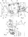
- FIGS. 3 to 7 a specific, only exemplary embodiment of not part of the control device 20 of the value document input and output section 18 described in the two first embodiments.
- the same reference numerals are used for corresponding devices.
- the part of a value document input and output section 18 without the control device 20 will be referred to as a value document module for simplicity's sake.
- the value document acceptance device 26 comprises along an input transport path T E an input pocket 38 for manually inputting individual value documents, a checking device 40 for determining a value of a value document and checking the validity or authenticity of a value document, an optional input transport interface 42 and an input transport device for transporting a the value document 46 inserted into the input tray 38 passes along or passes through the input transport path on the tester 40 to the input transport interface 42.
- the last input transport path portion T A 'terminating in a coupling end at the input transport interface 42 is substantially horizontal in this example.
- the input tray 38 has a side stop, not shown, on which a customer aligns the value document 46 laterally during insertion and pushes further.
- the input transport device has an input light barrier 47 for detecting a slot of a value document, driven transport rollers 48 and transport belt 50, which transport the inserted into the input tray value document 46 by the examining device 40, which is designed in this embodiment to recognize banknotes of a given currency and to check for authenticity, which are aligned laterally according to the stop.
- the input transport device has two parts 120 and 122, between which the transport path for the documents of value to be transported runs, which in this embodiment runs substantially horizontally in operation.
- the part 120 has the driven transport elements, in the example the transport rollers 48 and transport belt 50, thus forming a drive part, while the part 122, which is the counterpart to the part 120, more precisely a pressure member and not driven to the driven transport elements , Complementary transport elements 51, in the example pressure rollers and rigid guide elements.
- these parts 120 and 122 are arranged substantially parallel to each other and form between them the transport path for the value documents.
- the entire value document acceptance device 26 is connected to parallel side elements 124 of the skeleton 22 by means of an at least approximately orthogonal to the transport direction R of Transport path section T A 'and parallel to the determined by the drive and the pressure member 120 and 122 surface of the transport path path pivot axis 126 which is arranged in the region of the beginning of the transport path between an operating position in which a document of value along the of Parts 120 and 122 partially enclosed transport path to the buffer device 30 in the assumption position is transportable, and an opening position in which a manual access is possible at least on both ends of the transport path, hinged.
- the entire value document acceptance device 26, as shown in FIG Fig. 4 shown, swung down.
- the two parts of the input transport means 120 and 122 are pivotally mounted relative to each other, so that exposed by pivoting at least one of the parts relative to the other from an operating position to an open position, the transport path T A in the input transport means over its entire length outside of the test device 40 can be.
- the pressure part 122 is hinged to the drive part 120 for this purpose.
- a parallel to the pivot axis 126 extending pivot axis 128 is disposed near the front side of the input transport means on the drive member 120, so that the pressure member 122 can be pivoted in downwardly pivoted input transport means upwards.
- a locking of the parts 120 and 122 in the operating position can be done by a corresponding locking device, such as a snap mechanism, not shown.
- the testing device 40 (cf. Fig. 3 ) comprises on the one hand a means for detecting coupons, not shown in the figures, recognizes the coupons, their validity and value determined and outputs corresponding signals to the controller 20, in the example a bar code reader for reading an encrypted bar code and decryption of the represented by the barcode Data representing the value of the voucher.
- the checking device 40 furthermore has a banknote validator 52 for determining the type, in particular the recognition of a predetermined currency and the denomination of banknotes and for checking the authenticity of banknotes according to predetermined criteria. For example, the banknote validator CashRay 90 sold by the applicant can be used.
- the test device 40 then outputs test signals to the control device 20 in accordance with the result of the test, so that it has data which, inter alia, reproduces the type, the validity or the value of the value document.
- the checked value document 46 is then transported to the input transport interface 42, which serves to transfer the value document to the temporary storage device 30 and has a pair of driven rollers 54 for this purpose.
- the location of these rollers defines, at least in part, an acceptance location for the temporary memory device 30 in which it must reside in order to receive a value document output from the input transport interface 42.
- the temporary storage device 30 for occasional intermediate storage of at least two value documents has on a base body 56 via a temporary storage transport interface 58, a downstream buffer 60 for receiving, isolated buffering and delivery of isolated value documents on a transport path section, in the example designed as a replaceable module winding storage 62, and a fixedly connected to the main body 56 motor 64 for Operation of the winding store 62.
- the temporary storage transport interface 58 has a pair of transport rollers 66 and a drive device 68 which is coupled to the pair of transport rollers 66 by means of a belt and a gear transmission and which, like the motor 64, is actuated at least indirectly by the control device 20 and is connected to the latter for signal transmission via corresponding devices ,
- the intermediate storage device 30 can be moved between different coupling layers by means of the transport device 28 along a linear direction, which in the example is substantially vertical depending on the inclination of the installation surface of the device (cf. Fig. 6 ).
- the transport device 28 for guiding the temporary storage device 30 along a linear direction via parallel to the base frame 22 fixed guide rails 70 and movable between the guide rails base 56 on both sides via complementary guide means 72, in the example guide carriage, in which the guide rails 70 engage ,
- the transport device 28 optionally has for guidance via a pair of racks 74 mounted in parallel on the skeleton 22, between which the intermediate storage device 30 is movable.
- racks 74 mounted in parallel on the skeleton 22, between which the intermediate storage device 30 is movable.
- complementary gears 76 are arranged on opposite sides of the racks 74, which engage in the racks 74 and prevent tilting of the latching device 30.
- a drive device connected to the basic structure 22 is provided in this embodiment, which moves the intermediate storage device 30.
- the coupling takes place via a toothed belt transmission.
- a drive means 78 which drives a shaft 80 with a gear pair, and at the other end an axis 82 with a gear pair on the shaft 80 corresponding gear pair.
- To the gear pairs run two endless toothed belts 84 which are fixed to the main body 56 of the latching device 30, so that by movement of the toothed belt 84, the latching means 30 along the skeleton 22 relative to the value document acceptance means 26, the value document output device 24 and in particular the memory device 32 and the end memory 36 is movable up and down.
- the memory device 32 has memory 86, in this embodiment, three recycling memory for receiving, storing and output of value documents, such as winding storage, via an L-shaped retainer 88 for the recycling memory 86 and held on the holding device 88, for each the recycling memory 86 via a storage transport interface 90, by means of which value documents between the respective recycling memory and in a suitable coupling position located in front of this intermediate storage device 30 are transported back and forth.
- value documents such as winding storage
- the L-shaped holding device 88 has continuous receiving openings 92 for receiving the recycling memory 86, which are formed in the example by the gap between two mutually parallel L-shaped side walls 94.
- the recycling memories are implemented as tool-free removable and usable modules and in each case by means of first fastening devices, in the example mounting slots 96 in the side walls 94 and the first fastening means complementary first fastening means, in the example pins on the side walls of the recycling memory 86, on the holding device 88 releasably attachable. They can thus be easily exchanged.
- the holder of the recycling memory 86 is designed so that this each with an input / output port 98 for stored or stored value documents, which is located in a end of a coupling end to the storage transport interface storage transport path section, the Transport device 28 are facing, while an insertion or removal of the recycling memory can take place from the opposite direction.
- the memory transport interfaces 90 arranged in operation between the input-output openings 98 and the transport device 28 each comprise transport elements that are driven together. In the example, it is about a common belt drive 100 driven roller pairs 102, which are in the holding device 88, in the example in the side cheeks 94, stored.
- the storage transport interfaces 90, in the example the pairs of rollers 102 define storage locations which the temporary storage device 30, more precisely the temporary storage transport interface, must occupy for exchange with the respective recycling storage so that an exchange of a value document can be made between the temporary storage facility 30 and the respective recycling facility. Memory can be done.
- the side cheeks 94 are arranged so that the long legs with the mounting slots 96, and thus in particular the memory transport interfaces with their transport device 28 facing opening for documents of value, at least approximately parallel to the possible path of the intermediate storage device 30 are arranged.
- a receptacle 104 for a cassette 106 is optionally provided, which is used for receiving coupons and for receiving banknotes that were classified as non-genuine during the test.
- a memory transport interface is also provided for these, which is designed and arranged corresponding to the other memory transport interfaces of the memory device 32.
- the holding device 88 is further pivotably articulated to a lower, transversely to the direction of travel of the latching device 28 extending edge about an axis extending in the same direction, so that the memory device 32 between an operating position in which the memory transport interfaces are aligned so that a transport to the latching device is possible in one of the storage layers, and an opening position in which the storage transport interfaces are accessible, back and forth swiveled.
- All electrical connections of electrical devices of the memory device 32 for example, not shown electric motors for driving the recycling memory 86 or the memory transport interfaces 90, to other parts of the device, in particular the control device 20 via a harness, not shown, in the region of the pivot axis of the memory device 32 leads to the skeleton 22.
- This arrangement makes it possible, on the one hand, to be able to easily exchange the recycling memories 86 without having to move further parts as a housing door.
- the holding device 88 with the recycling memories 86 and the cassette 106, ie the storage device 32 can be simply pivoted away from the transport device 28 to eliminate transport disturbances (cf. Fig. 7 ).
- all other interfaces for the transfer of value documents between the intermediate storage device 30 and the recycling memories 86 or the cassette 106 are thus directly accessible. In this case, no electrical connections need to be solved, so that the elimination of congestion can be done very easily.
- the receptacle 34 is provided for serving as an end cash drawer 36, which also has a storage transport interface, which also defines a storage location and by means of which banknotes are transported from the buffer storage device in the terminal.
- a free-fall cassette is provided as the end memory 36, wherein the receptacle 34 is designed accordingly.
- the safe area 106 is separated from the housing area in which the storage device is arranged so that access to the safe area can be made independently of the other housing area. Both areas have separate locks that can only be unlocked with appropriate keys or authorizations. In this way, the final memory can be removed without any manipulation of parts of the device is possible. Conversely, it can be ensured that access to the contents of the vault area is prevented when the device for eliminating disturbances is opened.
- the recycling memory 86, the receptacle 104 and the cassette 106 received therein and the receptacle 34 for the end memory 36 are formed so that the input transport path, the winding memory 62 and said memories or cassettes with their input and / or output openings lie in a plane, ie are not offset from each other.
- the value-document output device 24 arranged above the checking device 40 is also used by the intermediate-storage device via an output transport interface 108, which defines at least one output position of the temporary storage device 30, value documents can be output from the temporary storage device.
- this is a simple output device with a bottom 110 and a resilient lid 112, at the end of a pinch roller 114 is formed, provided (see. Fig. 4 ).
- a checking device which is designed to check laterally oriented value documents
- a checking device which checks value documents which are transported centered with respect to the transport path.
- the input transport device then preferably has a device for centering the value documents.
- FIGS. 8 to 11 Another embodiment is in the FIGS. 8 to 11 shown. It differs from the first embodiment by the formation of the temporary storage device, the formation of the input transport device, the arrangement of the recycling memory in the storage device and a corresponding change of the control device.
- the same reference numerals are used and the explanations and variants of the preceding embodiments are also applicable here.
- Fig. 8a and 8b For the sake of clarity, the value document input and payment section 18 ', which is shown only very schematically, now has an intermediate storage device 30' (cf. Fig. 9 ) having two latches 130 and 132 and corresponding buffer transport interfaces 134 and 136.
- the buffer 132 is a buffer for a single value document and the buffer 130 is a buffer, in particular a coil, for at least two value documents that can be entered only occasionally successively in the buffer 130 or output from this.
- each of the input transport, storage transport cut and output transport interfaces there are two possible coupling layers for each of the input transport, storage transport cut and output transport interfaces, i. Acceptance, storage or discharge layers of the temporary storage transport 30 '.
- the buffer 130 may be formed as a reel as in the first embodiment, while the second buffer memory 132 is a memory for a single document of value, in the example a repository on the buffer 130.
- the intermediate transport interfaces 134 and 136 are constructed the same. Further, they are replaced by a common drive device 138 of the temporary storage device 30 'driven, whereby embodiments with a separate drive are conceivable.
- the intermediate memory 132 embodied as a single memory is designed so that it can store all value-document types permissible for the payment, in particular those having the greatest extent transversely to the transport direction.
- the buffer memory 130 only has to be designed to hold the value documents which are stored in the memory device.
- the input transport device is changed over the input transport device in two ways.
- the input transport device (cf. Fig. 10a ) via a modified input transport interface 42 'and via a first transport drive device 140 that drives the transport elements of the input transport device, which is unchanged from the input transport device except for the drive and the input transport interface 42', and a second transport drive device 142 which drives the input transport interface 42 '.
- the incoming transport device now has in the transport path via a check device 40 downstream switch, which can be transported between the first position in which a value document from the inspection device 40 through an input transport path section T A 'via the input transport interface 42' to the buffer device 30 'in one of the assumption (see. Fig. 10a ), and a second layer in which a value document from the temporary storage device 30 'in one of the Assumption levels in a holding area 146 under or next to the test device 40 can be transported (see. Fig. 10c ), is manufacturable and manufacturable.
- the second transport drive device 142 connected to and controlled by the modified control device 20 'for signal transmission is designed so that it can transport a value document to or from the intermediate storage device 30' in the holding region 146 in response to signals from the control device 20 '
- the position of the switch by a not shown, controlled by the control device 20 'switch machine is changeable.
- the offset is selected so that, when temporarily storing banknotes in the buffer 130 in which the banknotes are aligned with a predetermined edge parallel to the transport direction, and transferring the banknote of the type specified for the recycling store 86 to the recycling store, the distance of the center of the banknote in the buffer from the center in the recycling store of stored banknotes of the same type is reduced.
- the recycling memories 86 are all offset by the same amount in the same direction.
- the offset of the recycling memory 86 depending on the banknote types to be stored in these, for example denominations of banknotes of the same currency, may each be selected differently.
- FIG. 10 illustrates in the banknotes 166, 166 'of two different widths in the transport path from the inspection device 40 via the transport interfaces to the winding storage 130 of the buffer device 30' in the assumption layer L A1 with solid lines; IM in the winding storage 130 and in one of the recycling winding storage 86, which is drawn in the figure for the sake of clarity along the transport direction R shown in dashed lines.
- the banknotes Due to the orientation of the banknotes along their longitudinal edge, they pass into the winding store 130 in which they are likewise stored aligned along their longitudinal edge. As a result, they are arranged asymmetrically in the winding 168. With only a few notes, the storage is not affected. When transported to the recycling store, the situation changes in the Fig. 11 not shown, so that the banknotes would also be stored asymmetrically in the winding 168 along its longitudinal edge without the offset. However, in particular when using winding storages with two films running in parallel, a disturbance may occur in the case of the narrow banknotes 160 in the number of value documents possibly occurring in the recycling memories 86. As a result of the offset, the narrow banknotes move further into the center of the reel, so that a lower susceptibility to interference can be achieved even with a large number of stored banknotes.
- the controller 20 is modified from the controller 20 to drive means of the value document input and output section by outputting control signals so as to perform the following procedure.
- euro banknotes are used as banknotes in denominations of 5 euros, 10 euros, 20 euros, 50 euros, 100 euros, 200 euros and 500 euros.
- the first five denominations each have different latitudes and longitudes increasing with denomination, the last three different lengths increasing with denomination, but equal widths.
- the recycling storage 86 serve to receive banknotes of the three denominations 5 euros, 10 euros and 20 euros.
- a value document is supplied to the value-document acceptance device 26 ', it imports the value-document by means of the first transport-drive device 140. It outputs a signal to the control device 20 'which controls the transport device 28 so that it moves the temporary storage device 30' into the assumption position L E2 , provided that it is not already in this position. This is the assumption situation in which the entry transport interface 42 'faces the second staging transport interface 136, so that a value document can be stored in the staging memory 132.
- the control device 20 ' now controls the second transport drive device 142, if necessary, the switch and the temporary storage device 30', in this example the drive device 138 and thus the temporary storage transport interface 136 so that the value document is transported through the interfaces into the temporary storage 132, wherein in this embodiment, the rear end of the value document seen in the transport direction remains trapped in the staging transport interface 136.
- the staging transport interface 136 may be considered part of the cache 132.
- the value document acceptance device 26 determines meanwhile, depending on the embodiment by means of own evaluation devices and / or using the control device 20 ', if the value document is a valid voucher or according to predetermined examination criteria as a banknote of a valid currency and recognized as real banknote and what value the value document Has. Further, the controller 20 'determines, based on signals from the validator 40, whether the value document has been skewed for further processing.
- control means 20 reads in signals representing the type, the result of the authenticity check and the value, and stores the corresponding data.
- the value acceptance device 26 is driven so that initially no further value documents are accepted.
- the transport device 28 is driven so that it moves the latching means 30 'in the discharge position L A2 (see. Fig. 10b ) in which the staging transport interface 136 opposes the input of the value document output device 24, so that the value document can be output from the intermediate memory 132 to the value document output device 24.
- the intermediate storage device 30 ' in this example more precisely the drive device 138, is actuated so that the cached value document is output from the intermediate memory 132 to the value document output device 24, by means of which a return to the customer takes place. Thereafter, the control device 20 'controls the transport device 28 to move the temporary storage device 30' back to the acceptance position L E2 .
- control device 20 determines that the last-added document of value has been recognized as a valid coupon or banknote of a currency acceptable by the device, it compares, in the presence of a recognized banknote, as to whether its recognized value is greater than the largest denomination of the banknote bank notes to be stored in the storage device 32 'and / or whether the storage device 32' can no longer store banknotes of this denomination.
- the control device 20 performs a restoring of the value document from the intermediate memory 132 into the temporary memory 130 (cf. Fig. 10d to 10e ).
- the control means 20 controls the buffer means 30', in this example the drive means 138, and the input transport interface 42 ', in this example the second transport drive means 142 and, if necessary, the switch or its drive, so that the value document is output from the intermediate memory 132 into the holding region 146, wherein the trailing edge of the value document in the transport direction remains clamped in the input transport interface 42 '(cf. Fig. 10d ).
- the control device 20 controls the transport device 28 such that it moves the temporary storage device 30' into the acceptance position L E1 , in which a value document can be transported into the temporary storage device 130 through the input transport interface 42 '.
- the control device 20 'then stores data about the value of the value document, the type of the value document, information about the recognized authenticity of the value document and the position of the value document in the buffer device 30', in the example the buffer 130.
- controller 20 'initiates further retraction of another value document treated like the previous one.
- control means 20 in response to signals from the value document acceptor 26 and the other sections, continuously determines the total value of the funds deposited and compares this with the amount to be paid. If the total value exceeds the amount to be paid, it controls the payment device in such a way that it issues a corresponding indication, for example by means of a display device, not shown in the figures, to the depositor and does not accept any further means of payment.
- the control device 20 'then executes a storage step in which the assumed cached value documents are stored in the storage device and / or the final storage.
- the control device 20 ' depending on the location and the type of cached in the latch device 30' value documents and the level of the memory device 32, the transport device 28 so that these successively according to the type, in banknotes in particular the denomination of the next from the temporary storage device 30 'to the memory device 32' or the final memory 36 to be issued value document an axle a corresponding storage position and in this the next document of value to the memory device 32 'or, if the memory device 32' filled with banknotes of the denomination of the banknote to be dispensed the final memory 36 outputs.
- the memory device 32 'or the end memory 36 is driven accordingly to record the value document and to save.
- the storage step is completed when the assumed ones stored in the temporary storage device 30 ', more specifically, the temporary storage 130 Value documents are stored in the memory device 32 'or the final memory 36.
- control means 20 determines which bills to return as change or part of the change, depending on the number and denomination of notes stored in the storage means 32', the amount invoiced and the other currency supplied.
- the controller 20 ' In an output step, the controller 20 ', starting with the denomination stored at the bottom of the storage device 32', then controls the transport 28, the storage 32 'and the buffer 30' so; the temporary storage device 30 'successively stores respective storage layers in the individual denominations to be dispensed, and corresponding banknotes from the storage device 32' are stored there in the intermediate storage device 30 ', more precisely the intermediate storage device 130.
- the control device 20' controls the transport device 28 such that it moves the temporary storage device 30 'into the delivery position L A1 , in which value documents can be output from the temporary storage 130 to the value document issuing device 26 ,
- the first temporary storage transport interface 134 and the output transport interface 108 are opposite each other.
- the temporary storage device 30 ' controls the temporary storage device 30 ', more precisely the drive device of the intermediate storage device 130 and the drive device 138 (cf. Fig. 10g ), the cached value documents to the Value document output device 24.
- the output of the banknotes then takes place as change or part of the change. This ends the output step.
- transport device 28 moves to corresponding signals of the control device 20 'the temporary storage device 30' in the assumption L E2 .
- the issue of the bill of exchange in analogy to the second example of the method described above takes place before the storage of the accepted value documents in the storage device 32 'or the end memory 36.
- the steps of the method until the end of the deposit are the same as in the variant described immediately above. The last of these steps is that, when the total value exceeds the amount to be paid, the controller 20 'controls the payment device so that it outputs a corresponding indication, for example by means of a display device not shown in the figures, to the depositor and no further Accepts payment.
- the controller 20 ' determines which bills to return as change or part of the bill, depending on the number and denomination of bills stored in the storage means 32', the bill amount and the other currency supplied.
- the storage device 32 ' controls the transport device 28, the storage device 32 'and the temporary storage device 30' then so that the temporary storage device 30 'successively stores in the individual denominations to be issued corresponding storage positions and there corresponding banknotes from the memory device 32' in the temporary storage device 30 ', more precisely the temporary memory 130, are stored (see. Fig. 10g ).
- the control device 20' controls the transport device 28 such that it moves the temporary storage device 30 'into the delivery position L A1 , in which value documents can be output from the temporary storage 130 to the value document issuing device 26 ,
- the first temporary storage transport interface 134 and the output transport interface 108 are opposite each other.
- the temporary storage device 30 ' controls the temporary storage device 30 ', more precisely the drive device of the intermediate storage device 130 and the drive device 138 (cf. Fig. 10g ) to deliver the cached value documents to the value document output device 24.
- the output of the banknotes then takes place as change or part of the change.
- the intermediate storage device 30 ' more precisely the temporary storage 130, there are now only the paid-in value documents provided for storage in the storage device 32' and the final storage 36.
- the control device 20 controls the value documents and the fill level of the storage device 32 as a function of the position and type of the value documents cached in the intermediate storage device 30', in the example more precisely the intermediate storage device 130 the transport device 28 in such a way that it successively according to the type, in denomination banknotes, the next issued from the buffer means 30 'to the memory device 32' or the final memory 36 value document anaide a corresponding storage position and in this the next value document the memory device 32 'or, if the memory device 32' is filled with banknotes of the denomination of the banknote to be dispensed, to the final memory 36 emits.
- the memory device 32 'or the end memory 36 is driven accordingly to record the value document and to save.
- transport device 28 moves to corresponding signals of the control device 20 'the temporary storage device 30' in the assumption L E2 .
- a particularly favorable embodiment of the interfaces of the device which is also an example of a device for handling documents of value is in the Fig. 12 to 15 using the example of one of the recycling memories 86 of the memory device 32 as the first device, which has a transport path section 148 along which a value document is transported from the first device, and the buffers 130 and 132 as second devices which have a transport path section 150 along which a value document is transported to and / or out of the second devices.
- the first device could also be provided by the input transport device, wherein the transport path section the transport path section T A 'and the pair of rollers represent the input transport interface 42'.
- the transport device 28 represents a movement device, by means of which the second transport path sections 150 along a predetermined curve, here the substantially vertically extending, given by the guide rails 70 trajectory of the buffer device 30 'relative to the memory device 32' and the memory 86 and thus the first transport path section 148 is movable so that in at least one coupling position of the devices to each other, namely in the case that the temporary storage device occupies one of the assumption, a document of value from the transport path portion 148 of the first device in the assumption position corresponding transport path section of the second device is transportable.
- the curved section extends in a plane given by the curved section and the transport direction R in the transport path sections.
- the axes of rotation 152 and 154 are therefore aligned parallel to each other.
- the projecting portions 162 of the circumference of the rollers of a pair constitute the document-carrying and clamping portions and do not engage the recessed groove-like portions 164 of the rollers, so that the document of value is not deformed (see FIG. FIGS. 12 and 13 ).
- the pairs of rollers 156 and 158 are now arranged and designed such that on the one hand in the respective receiving position corresponding rollers 160 and 160 'of the pairs of rollers 156 and 158 intermeshing intermesh (see. FIGS. 12 and 14 ).
- the intermediate storage device 30 'and thus the pairs of rollers 158 move in or out of the receiving position, they are guided past one another in a meshing manner (cf. FIGS. 12 and 14 ).
- the identically formed rollers of the roller pairs 158 likewise have a comb-like profile, which, however, may differ from that of the other rollers, so that meshing can be achieved (cf. Fig. 14 ).
- the prominent areas of the roles face each other.
- a gap-free coupling of the transport path sections which is seen parallel to the transport direction, can be achieved, which permits a very low-interference operation.
- the input transport interface, the other memory transport interfaces 90, and the output transport interface 108 are all but the drive as the storage transport interface 90 is formed and aligned in the traversing direction of the buffer device 30 'and thus the second transport path sections 150 so that the recessed areas are aligned in this direction, so that the pairs of rollers 158 in the process of the buffer device 30' meshing through the pairs of rollers of physicallystransport , Storage transport and output transport interfaces.
- the interfaces differ in the nature of their drive.
- Only one roller is driven at each of the storage transport, input transport and output transport interfaces.
- a common drive device is provided for the storage transport interfaces, which coupled to the driven rollers via a belt.
- the input transport and output transport interfaces each have their own drive device, in the case of the input transport device a stepper motor.
- staging transport interfaces 134 and 136 have common drive means, at the staging storage transport interface 136 both rollers are mechanically coupled by gears, while at the staging transport interface 134 only the upper roller is driven.
- the coupling layer lie through a gap formed between the rollers of a respective pair of rollers, or through a line of contact along which the rollers of a respective one Touch pair of rolls, given lines in a plane with the coupling end of the transport path sections.
- the rollers comprise in this embodiment, in each case a plurality of identically formed wheels 161 ', which are held on a rotatably mounted shaft 161 or axis at the same distance from each other.
- the wheels each form the protruding areas.
- the outer diameter of the rollers is chosen between 13 mm and 25 mm and in this example is 16 mm.
- At least the protruding surface areas of the rollers, in particular the driven rollers, are made of an elastic material, in the example of a resilient polymeric material, which deforms somewhat as a document of value passes through the roller pair.
- This configuration of the transport interfaces or transport interface devices is advantageous for all transport interfaces or interface devices of the devices of the exemplary embodiments, in particular, the acceptance, buffer, storage and output transport interface.
- Variants of the embodiments described above differ by the design of the memory device 32 or 32 'and the training, in the example programming the control device 20 or 20'. All other properties are unchanged, so that the reference numerals and the explanations apply accordingly here.
- the memory device 32 "differs from those of the previous embodiments in that it has a further receptacle 170 for an output memory for dispensing individual banknotes, which has a stacking cassette 172 for a larger storage capacity and compared to the capacity of the recycling memories 86 a singler 174 for singling the documents of value from the stacking cassette.
- This stacking cassette can serve as a pure dispenser for banknotes of one of the denominations which are also stored in the recycling memories 86. In particular, this can store banknotes of frequently denominated denominations or banknotes of the smallest denomination.
- a memory transport interface 176 is again arranged.
- the control means is now modified from the control means of the preceding embodiments in that, in determining the type and number of bills to be dispensed, it takes into account the number and denomination of bills stored in the dispenser, and controls the conveyor to determine whether or not to pick the determined number of banknotes of the smallest denomination from the corresponding memory 86 falls below a minimum fill level of this memory. She controls in the output step the Storage device and the temporary storage device then so that they remove only as many banknotes from the memory 86 in the corresponding storage location, that the minimum level is not exceeded. It also controls the transport device to move the temporary storage device in a corresponding coupling position in front of the storage transport interface for the output memory. It then controls the output memory, the corresponding memory and buffer transport interface and the buffer device so that the still needed number of banknotes to be issued is stored from the payout memory into the buffer device. The following sub-steps of the output step remain unchanged.
- At least one of the recycling memories is a stack with a singler.
- the singler can be part of the stack or part of the storage device.
- Such memories make it possible to store a particularly large number of value documents or banknotes. It is possible, for example, only run the recycling memory for the lowest denomination as a stack, since the largest output requirement is expected for this denomination.
- the orientation may, depending on the design of the examination device, consist in a centering of the banknotes or a lateral orientation.
- the input tray is designed as an input tray for a pile of banknotes, which is followed by a singler for separating an inserted banknote stack.
- value document output device is designed as an output device for output of value documents as a clamped bundle or loose bundle.
- end memory 36 is not a free-fall cassette but a stamped cassette or a safety bag and the device accordingly has a modified receptacle for these final memory types.
- Still other embodiments differ from the previously described embodiments solely in that no vouchers are processed, and that accordingly the test device has no corresponding device and the programming of the control device is changed accordingly.
- the value document output device 24 may also be arranged below the examination device.
- control device is modified.
- the modification consists in that, when the control device has detected the end of a deposit or receives a cancellation signal that the customer has triggered via an input device of the device, does not perform a payout and storage step but rather drives the transport device, the buffer device is made to move the assumption situation into the Ausgabelage. If the temporary storage device is in this position, it controls it and the value document output device in such a way that the accepted value documents buffered in the temporary storage device are reissued.
- a further embodiment results when the first and second devices are not movable relative to each other, but are arranged in a fixed relative position to each other.
- a device for handling value documents for bridging longer sections is shown schematically. It is another rotatably mounted about a rotation axis roller pair provided between whose roles a value document is trapped during transport and whose roles in a section through the axis of rotation have a comb-like structure, and which meshes with the pair of rollers for the first or second device.
- the additional pair of rollers is formed as the second pair of rollers 158.
Landscapes
- Engineering & Computer Science (AREA)
- Mechanical Engineering (AREA)
- Physics & Mathematics (AREA)
- General Physics & Mathematics (AREA)
- Delivering By Means Of Belts And Rollers (AREA)
Claims (47)
- Appareil de manipulation de documents de valeur (46) comportant
au moins un premier dispositif (86) comportant un segment de chemin de transport (148) le long duquel un document de valeur (46) est transporté vers et/ou à partir du premier dispositif (86) et/ou dans le premier dispositif (86),
au moins un deuxième dispositif (30) comportant un segment de chemin de transport (150) le long duquel un document de valeur (46) est transporté vers et/ou à partir du deuxième dispositif (30) et/ou dans le deuxième dispositif (30),
cependant que les dispositifs (30, 86) sont agencés de telle façon qu'un document de valeur (46) peut être transporté du segment de chemin de transport (148) du premier dispositif (86) à celui du deuxième dispositif (30) et/ou du segment de chemin de transport (150) du deuxième dispositif (30) à celui du premier dispositif (86), et
respectivement à une extrémité de couplage (K) du segment respectif de chemin de transport (148, 150), dans une position fixe par rapport au segment respectif de chemin de transport (148, 150), une paire de rouleaux (156, 158) dont les rouleaux (160, 160'), respectivement montés de manière à pouvoir tourner autour d'un axe de rotation (152, 154), retiennent durant le transport un document de valeur (46) en le coinçant entre eux,
caractérisé en ce
que les rouleaux (160, 160') présentent, en coupe à travers l'axe de rotation (152, 154), une structure en forme de peigne,
cependant que les paires de rouleaux (156, 158) sont agencées et conçues de telle façon que les rouleaux (160) d'une première des paires de rouleaux (156) et les rouleaux correspondants (160') d'une deuxième des paires de rouleaux (158) s'imbriquent à la manière de peignes dans la position de couplage. - Appareil de manipulation de documents de valeur (46) comportant
au moins un premier dispositif (86) comportant un segment de chemin de transport (148) le long duquel un document de valeur (46) est transporté vers et/ou à partir du premier dispositif (86) et/ou dans le premier dispositif (86),
au moins un deuxième dispositif (30) comportant un segment de chemin de transport (150) le long duquel un document de valeur (46) est transporté vers et/ou à partir du deuxième dispositif (30) et/ou dans le deuxième dispositif (30),
caractérisé par un dispositif de déplacement (28) au moyen duquel le deuxième segment de chemin de transport (150) peut être déplacé le long d'une courbe prédéterminée relativement au premier segment de chemin de transport (148), de telle sorte que, dans au moins une position de couplage des dispositifs (30, 86) l'un par rapport à l'autre, un document de valeur (46) peut être transporté du segment de chemin de transport (148) du premier dispositif (86) à celui (150) du deuxième dispositif (30) et/ou du segment de chemin de transport (150) du deuxième dispositif (30) à celui du premier dispositif (86), et par
respectivement à une extrémité de couplage (K) du segment respectif de chemin de transport (148, 150), dans une position fixe par rapport au segment respectif de chemin de transport (148, 150), une paire de rouleaux (156, 158) dont les rouleaux (160, 160'), respectivement montés de manière à pouvoir tourner autour d'un axe de rotation (152, 154), guident et retiennent durant le transport un document de valeur (46) en le coinçant entre eux, et dont les rouleaux (160, 160') présentent, en coupe à travers l'axe de rotation (152, 154), une structure en forme de peigne,
cependant que les paires de rouleaux (156, 158) sont agencées et conçues de telle façon que les rouleaux (160) d'une première des paires de rouleaux (156) et les rouleaux correspondants (160') d'une deuxième des paires de rouleaux (158) s'imbriquent à la manière de peignes dans la position de couplage
et sont, pendant un déplacement vers ou depuis la position de couplage, guidés de telle façon qu'ils passent, à la manière de peignes, l'un près de l'autre. - Appareil selon la revendication 2, dans lequel le segment de la courbe s'étend dans un plan.
- Appareil selon la revendication 2 ou 3, lequel comporte au moins un autre dispositif (86) comportant un segment de chemin de transport (148) le long duquel un document de valeur (46) est transporté vers et/ou à partir de l'autre dispositif (86) et/ou dans l'autre dispositif (86), et qui est agencé dans une position fixe relativement au premier dispositif (86) le long du segment de la courbe, de telle sorte que, dans au moins une position de couplage des dispositifs (30, 86) les uns avec les autres, un document de valeur (46) peut être transporté du segment de chemin de transport (148) de l'autre dispositif (86) à celui du deuxième dispositif (30) et/ou du segment de chemin de transport (150) du deuxième dispositif (30) à celui de l'autre dispositif (86),
cependant que,
à une extrémité de couplage (K) du chemin de transport (148) de l'autre dispositif (86), dans une position fixe par rapport au segment de chemin de transport (148),
une paire de rouleaux (156) dont les rouleaux (160), respectivement montés de manière à pouvoir tourner autour d'un axe de rotation (152), retiennent durant le transport un document de valeur (46) en le coinçant entre eux, et dont les rouleaux (160) présentent, en coupe à travers l'axe de rotation (152), une structure en forme de peigne, est agencée,
cependant que les paires de rouleaux (156, 158), à l'extrémité du segment de chemin de transport (148, 150) de l'autre dispositif (86) et du deuxième dispositif (30), sont agencées et conçues de telle façon que les rouleaux (160) de la paire de rouleaux (156) à l'extrémité du segment de chemin de transport (148) de l'autre dispositif (86) et les rouleaux correspondants (160') de la paire de rouleaux (158) à l'extrémité du segment de chemin de transport (150) du deuxième dispositif (30) s'imbriquent à la manière de peignes dans la position de couplage et sont, pendant un déplacement vers ou depuis la position de couplage, guidés de telle façon qu'ils passent, à la manière de peignes, l'un près de l'autre. - Appareil selon la revendication 4, dans lequel les rouleaux des paires de rouleaux pour le premier et le deuxième dispositif (86) sont conçus de manière identique.
- Appareil selon une des revendications précédentes, dans lequel, dans la position de couplage, par une fente conçue entre les rouleaux (160) d'une paire de rouleaux respective (156) ou par une ligne de contact le long de laquelle les rouleaux (160) d'une paire de rouleaux respective (156) se touchent, des lignes données se trouvent dans un plan avec l'extrémité de couplage (K) d'au moins un des segments de chemin de transport (148, 150).
- Appareil selon une des revendications précédentes, lequel, pour au moins un rouleau d'une des paires de rouleaux, comporte un dispositif d'entraînement (68) destiné à faire tourner les rouleaux.
- Appareil selon la revendication 7, dans lequel le dispositif d'entraînement comprend un moteur pas-à-pas.
- Appareil selon une des revendications précédentes, dans lequel les mouvements de rotation des rouleaux d'au moins une des paires de rouleaux sont couplés, de préférence mécaniquement.
- Appareil selon une des revendications précédentes, dans lequel, pour les deux paires de rouleaux, respectivement un dispositif d'entraînement destiné à faire tourner au moins un des rouleaux des paires de rouleaux respectives est prévu.
- Appareil selon la revendication 4 ou selon une des revendications de 5 à 10 et la revendication 4, lequel comporte un dispositif commun d'entraînement qui entraîne respectivement au moins un rouleau des paires de rouleaux à une extrémité de couplage (K) des segments de chemin de transport (148) du premier et de l'autre dispositif (86).
- Appareil selon une des revendications précédentes, dans lequel les rouleaux (160, 160') des deux paires de rouleaux (156, 158) s'imbriquent à tel point que, lors d'une imbrication, l'éloignement des zones proéminentes des rouleaux (160) de la une paire de rouleaux (156) par rapport à l'axe (154) ou à la zone plus profonde des rouleaux (160') de la deuxième paire de rouleaux (158) est, dans un plan évoluant respectivement entre les axes de rotation (152) des rouleaux (160), situé entre 0,5 mm et 3mm.
- Appareil selon une des revendications précédentes, dans lequel le diamètre extérieur des rouleaux (160, 160') se situe entre 13 mm et 25 mm.
- Appareil selon une des revendications précédentes, dans lequel les rouleaux d'au moins une paire de rouleaux (156, 158) présentent un diamètre extérieur identique.
- Appareil selon la revendication 14, dans lequel les rouleaux (160, 160') des paires de rouleaux (156, 158) pour le premier et le deuxième segment de chemin de transport (148, 150) présentent un diamètre extérieur identique.
- Appareil selon une des revendications précédentes, dans lequel au moins les zones de surface proéminentes d'au moins les rouleaux entraînés consistent en un matériau élastique.
- Appareil selon la revendication 2 ou selon une des revendications de 3 à 16 et la revendication 2, lequel est conçu pour la réception et la vérification de documents de valeur (46) ainsi que pour la délivrance de documents de valeur (46), et comporte en outre :un dispositif de vérification (40) destiné à la vérification de l'authenticité de documents de valeur (46) introduits,un dispositif de réservoir (32) qui, en tant que premier et autres dispositifs, comprend au moins deux réservoirs (86) pour l'entreposage d'au moins deux différents types de documents de valeur (46), de telle sorte qu'un document de valeur (46) de chacun des deux types peut, indépendamment de l'ordre de l'insertion de documents de valeur (46) dans le dispositif de réservoir (32), être délivré au choix depuis le dispositif de réservoir (32), et que les paires de rouleaux (102) constituent respectivement des points de segment de transport de réservoir (90),en tant que deuxième dispositif, un réservoir intermédiaire d'un dispositif de réservoir (30) intermédiaire destiné à l'entreposage intermédiaire, sous forme déliassée, d'au moins deux documents de valeur (46) vérifiés,lequel, entre au moins une position de réception (LE) dans laquelle des documents de valeur (46) amenés depuis le dispositif de vérification (40) peuvent être entreposés intermédiairement dans le dispositif de réservoir intermédiaire (30), et des positions d'entreposage (LS1, LS2) représentant des positions de couplage affectées aux réservoirs (86) dans lesquelles au moins quelques uns des documents de valeur (46) entreposés intermédiairement dans le dispositif de réservoir intermédiaire (30) peuvent être transportés depuis le dispositif de réservoir intermédiaire (30) jusque dans le réservoir (86) respectif, peut être déplacé,cependant que la paire de rouleaux (66) correspondantes est une partie d'une passerelle de transport de réservoir intermédiaire (58), et,en tant que dispositif de déplacement, un dispositif de transport (28) au moyen duquel le dispositif de réservoir intermédiaire (30) est déplaçable entre la position de réception (LE) et les positions d'entreposage (LS1, LS2).
- Appareil selon la revendication 17, dans lequel au moins un des réservoirs (86) est un réservoir (86) à partir duquel des documents de valeur (46) peuvent être délivrés sous forme déliassée.
- Appareil selon une des revendications 17 ou 18, dans lequel au moins un des réservoirs (86) est un réservoir (86) dans lequel au moins deux documents de valeur peuvent être entreposés sous forme déliassée.
- Appareil selon la revendication 18 ou 19, dans lequel le un réservoir (86) est un réservoir à enroulement.
- Appareil selon une des revendications précédentes de 17 à 20, dans lequel au moins un des réservoirs (86) est un réservoir dans lequel des documents de valeur peuvent être entreposés sous forme de piles.
- Appareil selon la revendication 21, dans lequel, pour le réservoir (86), une déliasseuse est prévue.
- Appareil selon une des revendications de 17 à 22, dans lequel le dispositif de réservoir (32") comporte au moins un réservoir de délivrance à partir duquel des documents de valeur sont seulement délivrés.
- Appareil selon une des revendications de 17 à 23, dans lequel les au moins deux réservoirs (86) sont agencés de telle façon que la au moins une position de réception (LE) et les positions d'entreposage (LS1, LS2) se trouvent le long d'un trajet linéaire.
- Appareil selon la revendication 24, dans lequel le trajet linéaire s'étend essentiellement verticalement.
- Appareil selon une des revendications de 17 à 25, dans lequel un dispositif de retenue (88) muni d'au moins un logement de réception (92) est prévu pour au moins un des deux réservoirs (86), et dans lequel le au moins un réservoir (86) est réalisé sous forme de module pouvant être relié au logement de réception (92) respectif puis en être à nouveau détaché.
- Appareil selon la revendication 26, dans lequel le logement de réception (92) et le au moins un réservoir (86) sont conçus de telle façon que c'est sans outil que le au moins un réservoir (86) peut être relié au logement de réception (92) respectif puis en être détaché.
- Appareil selon une des revendications de 17 à 27, dans lequel le dispositif de réservoir intermédiaire (30') dispose d'un réservoir intermédiaire (130) pour au moins deux documents de valeur (46) qui ne peuvent que l'un après l'autre être insérés dans le réservoir intermédiaire (130) ou délivrés à partir de ce dernier.
- Appareil selon une des revendications de 17 à 28, dans lequel le dispositif de réservoir intermédiaire (30') dispose d'au moins deux réservoirs intermédiaires (130, 132).
- Appareil selon la revendications 29, dans lequel, des au moins deux réservoirs intermédiaires (130, 132), au moins un est un réservoir intermédiaire (132) pour un document de valeur individuel (46).
- Appareil selon la revendications 29 ou 30, dans lequel, des au moins deux réservoirs intermédiaires (130, 132), au moins un est un réservoir intermédiaire (130), en particulier un réservoir à enroulement, pour au moins deux documents de valeur (46) qui ne peuvent que l'un après l'autre être insérés dans le réservoir intermédiaire (130) ou délivrés à partir de ce dernier.
- Appareil selon une des revendications de 29 à 30, dans lequel les au moins deux réservoirs intermédiaires sont respectivement des réservoirs intermédiaires pour un document de valeur individuel (46) dans lesquels ou à partir desquels, au choix, un document de valeur (46) peut être inséré ou délivré.
- Appareil selon une des revendications de 29 à 31, dans lequel le dispositif de réservoir intermédiaire (30') comporte pour chacun des réservoirs intermédiaires (130, 132) une passerelle de transport de réservoir intermédiaire (134, 136) au moyen de laquelle un document de valeur (46) peut être amené au réservoir intermédiaire (130, 132) ou aux réservoirs intermédiaires respectifs (130, 132) et/ou être retiré du réservoir intermédiaire (130, 132) ou des réservoirs intermédiaires respectifs (130, 132).
- Appareil selon la revendication 32, dans lequel, pour les passerelles de transport de réservoir intermédiaire (134, 136), un entraînement (138) commun est prévu.
- Appareil selon une des revendications de 17 à 33, dans lequel le dispositif de transport constitue conjointement avec le dispositif de réservoir intermédiaire un moteur électrique linéaire.
- Appareil selon une des revendications de 17 à 33, dans lequel le dispositif de transport (28) comprend un dispositif d'entraînement (78) agencé de manière fixe relativement à un élément de base (22) de l'appareil.
- Appareil selon la revendication 35, dans lequel le dispositif de transport (28) comprend une courroie (84) reliée au dispositif de réservoir intermédiaire (30') et/ou une chaîne reliée au dispositif de réservoir intermédiaire, laquelle entraîne le dispositif d'entraînement (78) du dispositif de transport (28).
- Appareil selon une des revendications de 17 à 36, dans lequel le dispositif de transport (28) comporte une broche ainsi qu'un dispositif d'entraînement destiné à faire tourner la broche, et le dispositif de réservoir intermédiaire comporte un élément interagissant avec la broche, de telle sorte que c'est en faisant tourner la broche que l'entraînement déplace le dispositif de réservoir intermédiaire.
- Appareil selon une des revendications de 17 à 37, dans lequel le dispositif de transport comprend un dispositif d'entraînement relié au dispositif de réservoir intermédiaire.
- Appareil selon la revendication 38, dans lequel le dispositif de transport comporte une crémaillère reliée de manière fixe au dispositif de réservoir, et le dispositif de réservoir intermédiaire comporte un pignon, entraîné par le dispositif d'entraînement, qui s'engage dans la crémaillère.
- Appareil selon une des revendications de 17 à 38, lequel comporte un dispositif de transport d'entrée (44) au moyen duquel des documents de valeur individuels (46) peuvent être transportés depuis un casier d'insertion (38) à travers le dispositif de vérification (40).
- Appareil selon la revendication 40, dans lequel le dispositif de dispositif de transport d'entrée (44) comporte un dispositif de passerelle de transport d'entrée (42) au moyen duquel des documents de valeur (46) ayant commencé à être transportés par le dispositif de vérification (40) peuvent être transportés dans le dispositif de réservoir intermédiaire (30) se trouvant dans la au moins une position de réception.
- Appareil selon la revendication 40 ou 41, dans lequel le dispositif de transport d'entrée (44) et/ou le dispositif de passerelle de transport d'entrée (42) ainsi que le dispositif de vérification (40) sont conçus pour un transport bidirectionnel, ce qui ne signifie néanmoins pas nécessairement que le dispositif de vérification doive permettre aussi une vérification dans le cas d'un transport bidirectionnel.
- Appareil selon une des revendications de 17 à 42, lequel comporte un autre réservoir (106) ayant un position d'entreposage (L24) lui étant affectée, dans lequel des documents de valeur (46) peuvent être entreposés depuis le dispositif de réservoir intermédiaire (30) dans la position d'entreposage (L24) correspondante, mais à partir duquel des documents de valeur (46) ne peuvent pas être remis au dispositif de réservoir intermédiaire (30).
- Appareil selon la revendication 43, dans lequel l'autre réservoir (106) est agencé dans le dispositif de réservoir (32).
- Appareil selon une des revendications de 17 à 44, lequel comporte un réservoir de délivrance et/ou un logement de réception (170) pour un réservoir de délivrance depuis lequel des documents de valeur (46) peuvent être transportés sous forme déliassée dans le dispositif de réservoir intermédiaire (30).
- Appareil selon la revendication 45, dans lequel le réservoir de délivrance est un réservoir à empilement, le réservoir à empilement ou le logement de réception (170) possédant une déliasseuse (174).
Applications Claiming Priority (2)
| Application Number | Priority Date | Filing Date | Title |
|---|---|---|---|
| DE102007020778A DE102007020778A1 (de) | 2007-05-03 | 2007-05-03 | Vorrichtung zur Handhabung von Wertdokumenten |
| PCT/EP2008/003558 WO2008135240A1 (fr) | 2007-05-03 | 2008-05-02 | Appareil destiné manipuler des documents de valeur |
Publications (2)
| Publication Number | Publication Date |
|---|---|
| EP2152619A1 EP2152619A1 (fr) | 2010-02-17 |
| EP2152619B1 true EP2152619B1 (fr) | 2017-09-06 |
Family
ID=39712116
Family Applications (1)
| Application Number | Title | Priority Date | Filing Date |
|---|---|---|---|
| EP08749300.3A Not-in-force EP2152619B1 (fr) | 2007-05-03 | 2008-05-02 | Appareil destiné à manipuler des documents de valeur |
Country Status (5)
| Country | Link |
|---|---|
| US (1) | US7922173B2 (fr) |
| EP (1) | EP2152619B1 (fr) |
| CA (1) | CA2684668C (fr) |
| DE (1) | DE102007020778A1 (fr) |
| WO (1) | WO2008135240A1 (fr) |
Families Citing this family (4)
| Publication number | Priority date | Publication date | Assignee | Title |
|---|---|---|---|---|
| DE102009035183A1 (de) | 2009-07-29 | 2011-02-10 | Giesecke & Devrient Gmbh | Vorrichtung zur Handhabung von Wertdokumenten |
| US8876110B2 (en) * | 2011-11-10 | 2014-11-04 | Assa Abloy Ab | Credential manufacturing device substrate shuttle |
| TW201406562A (zh) * | 2012-08-15 | 2014-02-16 | Hon Hai Prec Ind Co Ltd | 列印文檔儲存裝置 |
| US20160234139A1 (en) * | 2015-02-09 | 2016-08-11 | Angela Christine Botner | Classification Based Email Construction, Work Flow, and Dashboard Rendering |
Citations (3)
| Publication number | Priority date | Publication date | Assignee | Title |
|---|---|---|---|---|
| US4002280A (en) * | 1976-05-12 | 1977-01-11 | Colenta American Corporation | Film transport apparatus utilizing rollers to provide a U-path |
| JPH05178531A (ja) * | 1991-12-27 | 1993-07-20 | Laurel Bank Mach Co Ltd | 紙葉類処理機 |
| JP2006206208A (ja) * | 2005-01-25 | 2006-08-10 | Oki Electric Ind Co Ltd | 紙葉類処理装置 |
Family Cites Families (22)
| Publication number | Priority date | Publication date | Assignee | Title |
|---|---|---|---|---|
| AT340826B (de) * | 1975-12-12 | 1978-01-10 | Gao Ges Automation Org | Transportsystem fur flaches fordergut, wie geldscheine, belege u.dgl. |
| US4725372A (en) * | 1980-10-27 | 1988-02-16 | The Dow Chemical Company | Aqueous wellbore service fluids |
| US4695389A (en) * | 1984-03-16 | 1987-09-22 | Dowell Schlumberger Incorporated | Aqueous gelling and/or foaming agents for aqueous acids and methods of using the same |
| JPH02249832A (ja) * | 1989-03-20 | 1990-10-05 | Fuji Xerox Co Ltd | 用紙搬送装置 |
| DE4417050A1 (de) * | 1994-05-14 | 1995-11-16 | Kodak Ag | Vorrichtung zum Transport von blattförmigem Aufzeichnungsmaterial |
| US5551516A (en) * | 1995-02-17 | 1996-09-03 | Dowell, A Division Of Schlumberger Technology Corporation | Hydraulic fracturing process and compositions |
| US5964295A (en) * | 1996-10-09 | 1999-10-12 | Schlumberger Technology Corporation, Dowell Division | Methods and compositions for testing subterranean formations |
| GB9626835D0 (en) | 1996-12-24 | 1997-02-12 | Ncr Int Inc | Apparatus for detecting the passage of multiple superposed sheets along a feed path |
| JP3547283B2 (ja) * | 1997-03-26 | 2004-07-28 | 株式会社リコー | 用紙反転装置 |
| US5887653A (en) * | 1997-08-15 | 1999-03-30 | Plainsman Technology, Inc. | Method for clay stabilization |
| US6186339B1 (en) * | 1999-03-25 | 2001-02-13 | Cashcode Company | Combination bill accepting and bill dispensing device |
| US6437040B2 (en) * | 1999-09-01 | 2002-08-20 | Rhodia Chimie | Water-soluble block copolymers comprising a hydrophilic block and a hydrophobic block |
| US6857485B2 (en) * | 2000-02-11 | 2005-02-22 | M-I Llc | Shale hydration inhibition agent and method of use |
| US6762154B2 (en) * | 2000-09-21 | 2004-07-13 | Schlumberger Technology Corporation | Viscoelastic surfactant fluids stable at high brine concentrations |
| JP5193409B2 (ja) * | 2001-09-21 | 2013-05-08 | 株式会社東芝 | 紙葉類処理装置と紙葉類処理装置の点検方法とテスト媒体 |
| US6787506B2 (en) * | 2002-04-03 | 2004-09-07 | Nalco Energy Services, L.P. | Use of dispersion polymers as friction reducers in aqueous fracturing fluids |
| EP1433728A1 (fr) * | 2002-12-23 | 2004-06-30 | Mars Incorporated | Convoyeur pour billets de banque |
| ES2389561T3 (es) | 2003-03-10 | 2012-10-29 | Diebold, Incorporated | Máquina bancaria automática de dispensación de efectivo y método |
| US7311303B2 (en) * | 2003-07-25 | 2007-12-25 | Hewlett-Packard Development Company, L.P. | Apparatus and method for distributing print media |
| US7084092B2 (en) * | 2003-08-25 | 2006-08-01 | M-I L.L.C. | Shale hydration inhibition agent and method of use |
| US7192907B2 (en) * | 2003-09-03 | 2007-03-20 | M-I L.L.C. | High performance water-based drilling mud and method of use |
| JP4524258B2 (ja) * | 2006-02-17 | 2010-08-11 | 日立オムロンターミナルソリューションズ株式会社 | 通帳搬送ローラ装置 |
-
2007
- 2007-05-03 DE DE102007020778A patent/DE102007020778A1/de not_active Withdrawn
-
2008
- 2008-05-02 US US12/149,481 patent/US7922173B2/en not_active Expired - Fee Related
- 2008-05-02 EP EP08749300.3A patent/EP2152619B1/fr not_active Not-in-force
- 2008-05-02 CA CA2684668A patent/CA2684668C/fr active Active
- 2008-05-02 WO PCT/EP2008/003558 patent/WO2008135240A1/fr active Application Filing
Patent Citations (3)
| Publication number | Priority date | Publication date | Assignee | Title |
|---|---|---|---|---|
| US4002280A (en) * | 1976-05-12 | 1977-01-11 | Colenta American Corporation | Film transport apparatus utilizing rollers to provide a U-path |
| JPH05178531A (ja) * | 1991-12-27 | 1993-07-20 | Laurel Bank Mach Co Ltd | 紙葉類処理機 |
| JP2006206208A (ja) * | 2005-01-25 | 2006-08-10 | Oki Electric Ind Co Ltd | 紙葉類処理装置 |
Also Published As
| Publication number | Publication date |
|---|---|
| EP2152619A1 (fr) | 2010-02-17 |
| US20090051102A1 (en) | 2009-02-26 |
| DE102007020778A1 (de) | 2008-11-06 |
| CA2684668A1 (fr) | 2008-11-13 |
| CA2684668C (fr) | 2012-10-30 |
| WO2008135240A8 (fr) | 2008-12-31 |
| US7922173B2 (en) | 2011-04-12 |
| WO2008135240A1 (fr) | 2008-11-13 |
Similar Documents
| Publication | Publication Date | Title |
|---|---|---|
| EP1485883B1 (fr) | Dispositif de manipulation de billets de banque avec selecteur multi-chemin | |
| DE69935111T2 (de) | Maschine zur Einnahme und Ausgabe von Geldscheinen | |
| DE60203513T2 (de) | Vorrichtung zur annahme von bogen und wiederverwendungssystem | |
| EP2036052A2 (fr) | Système de traitement de documents de valeur | |
| DE3917699A1 (de) | Banknotenannahme- und -ausgabemaschine | |
| DE3915030A1 (de) | Vorrichtung zum behandeln von banknoten | |
| DE3743386C2 (de) | Maschine zur Annahme und Abgabe von Banknoten | |
| WO2007147607A2 (fr) | Système de traitement de documents de valeur | |
| DE3321657C2 (fr) | ||
| DE68925287T2 (de) | Banknotenverarbeitungsvorrichtung | |
| EP2152619B1 (fr) | Appareil destiné à manipuler des documents de valeur | |
| DE3321637C2 (fr) | ||
| WO2008148521A1 (fr) | Dispositif pour le paiement du montant donné d'une facture et procédé pour l'acceptation de documents de valeur et pour l'émission de documents de valeur enregistrés dans un dispositif de mémoire | |
| WO2008135242A1 (fr) | Dispositif de réception et d'émission de documents de valeur | |
| EP2199988A2 (fr) | Dispositif de réception et d'émission de documents de valeur | |
| EP0106109B1 (fr) | Dispositif pour le transport et l'empilage de billets de banque dans une machine de vente | |
| EP2156417B1 (fr) | Dispositif pour recevoir et émettre des documents de valeur | |
| WO2008135241A1 (fr) | Appareil pour accepter et distribuer des documents de valeur | |
| DE102011115136A1 (de) | Vorrichtung und Verfahren zur Bearbeitung von Banknoten | |
| EP2419356B1 (fr) | Dispositif pour entrer un ou plusieurs documents de valeur | |
| DE102010037316A1 (de) | Vorrichtung zur Handhabung von Wertscheinen mit zwei Eingabe- und/oder Ausgabeeinheiten | |
| WO2009100825A1 (fr) | Dispositif pour réceptionner et délivrer des billets de banque | |
| DE60123473T2 (de) | Maschine und verfahren zum ausgeben von banknoten | |
| WO2009083139A1 (fr) | Installation de réception et d'émission de billets de banque | |
| WO2017162321A1 (fr) | Guichet automatique bancaire |
Legal Events
| Date | Code | Title | Description |
|---|---|---|---|
| PUAI | Public reference made under article 153(3) epc to a published international application that has entered the european phase |
Free format text: ORIGINAL CODE: 0009012 |
|
| 17P | Request for examination filed |
Effective date: 20091203 |
|
| AK | Designated contracting states |
Kind code of ref document: A1 Designated state(s): AT BE BG CH CY CZ DE DK EE ES FI FR GB GR HR HU IE IS IT LI LT LU LV MC MT NL NO PL PT RO SE SI SK TR |
|
| AX | Request for extension of the european patent |
Extension state: AL BA MK RS |
|
| DAX | Request for extension of the european patent (deleted) | ||
| RIC1 | Information provided on ipc code assigned before grant |
Ipc: B65H 83/02 20060101ALI20170208BHEP Ipc: B65H 3/44 20060101ALI20170208BHEP Ipc: B65H 29/00 20060101ALI20170208BHEP Ipc: G07D 11/00 20060101ALI20170208BHEP Ipc: B65H 29/12 20060101AFI20170208BHEP |
|
| GRAP | Despatch of communication of intention to grant a patent |
Free format text: ORIGINAL CODE: EPIDOSNIGR1 |
|
| INTG | Intention to grant announced |
Effective date: 20170321 |
|
| GRAS | Grant fee paid |
Free format text: ORIGINAL CODE: EPIDOSNIGR3 |
|
| GRAA | (expected) grant |
Free format text: ORIGINAL CODE: 0009210 |
|
| RAP1 | Party data changed (applicant data changed or rights of an application transferred) |
Owner name: GIESECKE+DEVRIENT CURRENCY TECHNOLOGY GMBH |
|
| AK | Designated contracting states |
Kind code of ref document: B1 Designated state(s): AT BE BG CH CY CZ DE DK EE ES FI FR GB GR HR HU IE IS IT LI LT LU LV MC MT NL NO PL PT RO SE SI SK TR |
|
| REG | Reference to a national code |
Ref country code: GB Ref legal event code: FG4D Free format text: NOT ENGLISH |
|
| REG | Reference to a national code |
Ref country code: CH Ref legal event code: EP Ref country code: AT Ref legal event code: REF Ref document number: 925641 Country of ref document: AT Kind code of ref document: T Effective date: 20170915 |
|
| REG | Reference to a national code |
Ref country code: IE Ref legal event code: FG4D Free format text: LANGUAGE OF EP DOCUMENT: GERMAN |
|
| REG | Reference to a national code |
Ref country code: CH Ref legal event code: NV Representative=s name: PATENTANWAELTE SCHAAD, BALASS, MENZL AND PARTN, CH |
|
| REG | Reference to a national code |
Ref country code: DE Ref legal event code: R096 Ref document number: 502008015600 Country of ref document: DE |
|
| REG | Reference to a national code |
Ref country code: NL Ref legal event code: MP Effective date: 20170906 |
|
| REG | Reference to a national code |
Ref country code: LT Ref legal event code: MG4D |
|
| PG25 | Lapsed in a contracting state [announced via postgrant information from national office to epo] |
Ref country code: LT Free format text: LAPSE BECAUSE OF FAILURE TO SUBMIT A TRANSLATION OF THE DESCRIPTION OR TO PAY THE FEE WITHIN THE PRESCRIBED TIME-LIMIT Effective date: 20170906 Ref country code: NO Free format text: LAPSE BECAUSE OF FAILURE TO SUBMIT A TRANSLATION OF THE DESCRIPTION OR TO PAY THE FEE WITHIN THE PRESCRIBED TIME-LIMIT Effective date: 20171206 Ref country code: HR Free format text: LAPSE BECAUSE OF FAILURE TO SUBMIT A TRANSLATION OF THE DESCRIPTION OR TO PAY THE FEE WITHIN THE PRESCRIBED TIME-LIMIT Effective date: 20170906 Ref country code: FI Free format text: LAPSE BECAUSE OF FAILURE TO SUBMIT A TRANSLATION OF THE DESCRIPTION OR TO PAY THE FEE WITHIN THE PRESCRIBED TIME-LIMIT Effective date: 20170906 Ref country code: SE Free format text: LAPSE BECAUSE OF FAILURE TO SUBMIT A TRANSLATION OF THE DESCRIPTION OR TO PAY THE FEE WITHIN THE PRESCRIBED TIME-LIMIT Effective date: 20170906 |
|
| PG25 | Lapsed in a contracting state [announced via postgrant information from national office to epo] |
Ref country code: LV Free format text: LAPSE BECAUSE OF FAILURE TO SUBMIT A TRANSLATION OF THE DESCRIPTION OR TO PAY THE FEE WITHIN THE PRESCRIBED TIME-LIMIT Effective date: 20170906 Ref country code: ES Free format text: LAPSE BECAUSE OF FAILURE TO SUBMIT A TRANSLATION OF THE DESCRIPTION OR TO PAY THE FEE WITHIN THE PRESCRIBED TIME-LIMIT Effective date: 20170906 Ref country code: BG Free format text: LAPSE BECAUSE OF FAILURE TO SUBMIT A TRANSLATION OF THE DESCRIPTION OR TO PAY THE FEE WITHIN THE PRESCRIBED TIME-LIMIT Effective date: 20171206 Ref country code: GR Free format text: LAPSE BECAUSE OF FAILURE TO SUBMIT A TRANSLATION OF THE DESCRIPTION OR TO PAY THE FEE WITHIN THE PRESCRIBED TIME-LIMIT Effective date: 20171207 |
|
| PG25 | Lapsed in a contracting state [announced via postgrant information from national office to epo] |
Ref country code: NL Free format text: LAPSE BECAUSE OF FAILURE TO SUBMIT A TRANSLATION OF THE DESCRIPTION OR TO PAY THE FEE WITHIN THE PRESCRIBED TIME-LIMIT Effective date: 20170906 |
|
| PG25 | Lapsed in a contracting state [announced via postgrant information from national office to epo] |
Ref country code: PL Free format text: LAPSE BECAUSE OF FAILURE TO SUBMIT A TRANSLATION OF THE DESCRIPTION OR TO PAY THE FEE WITHIN THE PRESCRIBED TIME-LIMIT Effective date: 20170906 Ref country code: RO Free format text: LAPSE BECAUSE OF FAILURE TO SUBMIT A TRANSLATION OF THE DESCRIPTION OR TO PAY THE FEE WITHIN THE PRESCRIBED TIME-LIMIT Effective date: 20170906 Ref country code: CZ Free format text: LAPSE BECAUSE OF FAILURE TO SUBMIT A TRANSLATION OF THE DESCRIPTION OR TO PAY THE FEE WITHIN THE PRESCRIBED TIME-LIMIT Effective date: 20170906 |
|
| REG | Reference to a national code |
Ref country code: FR Ref legal event code: PLFP Year of fee payment: 11 |
|
| PG25 | Lapsed in a contracting state [announced via postgrant information from national office to epo] |
Ref country code: IT Free format text: LAPSE BECAUSE OF FAILURE TO SUBMIT A TRANSLATION OF THE DESCRIPTION OR TO PAY THE FEE WITHIN THE PRESCRIBED TIME-LIMIT Effective date: 20170906 Ref country code: IS Free format text: LAPSE BECAUSE OF FAILURE TO SUBMIT A TRANSLATION OF THE DESCRIPTION OR TO PAY THE FEE WITHIN THE PRESCRIBED TIME-LIMIT Effective date: 20180106 Ref country code: EE Free format text: LAPSE BECAUSE OF FAILURE TO SUBMIT A TRANSLATION OF THE DESCRIPTION OR TO PAY THE FEE WITHIN THE PRESCRIBED TIME-LIMIT Effective date: 20170906 Ref country code: SK Free format text: LAPSE BECAUSE OF FAILURE TO SUBMIT A TRANSLATION OF THE DESCRIPTION OR TO PAY THE FEE WITHIN THE PRESCRIBED TIME-LIMIT Effective date: 20170906 |
|
| REG | Reference to a national code |
Ref country code: DE Ref legal event code: R097 Ref document number: 502008015600 Country of ref document: DE |
|
| PLBE | No opposition filed within time limit |
Free format text: ORIGINAL CODE: 0009261 |
|
| STAA | Information on the status of an ep patent application or granted ep patent |
Free format text: STATUS: NO OPPOSITION FILED WITHIN TIME LIMIT |
|
| PG25 | Lapsed in a contracting state [announced via postgrant information from national office to epo] |
Ref country code: DK Free format text: LAPSE BECAUSE OF FAILURE TO SUBMIT A TRANSLATION OF THE DESCRIPTION OR TO PAY THE FEE WITHIN THE PRESCRIBED TIME-LIMIT Effective date: 20170906 |
|
| 26N | No opposition filed |
Effective date: 20180607 |
|
| PG25 | Lapsed in a contracting state [announced via postgrant information from national office to epo] |
Ref country code: SI Free format text: LAPSE BECAUSE OF FAILURE TO SUBMIT A TRANSLATION OF THE DESCRIPTION OR TO PAY THE FEE WITHIN THE PRESCRIBED TIME-LIMIT Effective date: 20170906 |
|
| PG25 | Lapsed in a contracting state [announced via postgrant information from national office to epo] |
Ref country code: MT Free format text: LAPSE BECAUSE OF FAILURE TO SUBMIT A TRANSLATION OF THE DESCRIPTION OR TO PAY THE FEE WITHIN THE PRESCRIBED TIME-LIMIT Effective date: 20170906 |
|
| REG | Reference to a national code |
Ref country code: BE Ref legal event code: MM Effective date: 20180531 |
|
| PG25 | Lapsed in a contracting state [announced via postgrant information from national office to epo] |
Ref country code: MC Free format text: LAPSE BECAUSE OF FAILURE TO SUBMIT A TRANSLATION OF THE DESCRIPTION OR TO PAY THE FEE WITHIN THE PRESCRIBED TIME-LIMIT Effective date: 20170906 |
|
| REG | Reference to a national code |
Ref country code: IE Ref legal event code: MM4A |
|
| PG25 | Lapsed in a contracting state [announced via postgrant information from national office to epo] |
Ref country code: LU Free format text: LAPSE BECAUSE OF NON-PAYMENT OF DUE FEES Effective date: 20180502 |
|
| PG25 | Lapsed in a contracting state [announced via postgrant information from national office to epo] |
Ref country code: IE Free format text: LAPSE BECAUSE OF NON-PAYMENT OF DUE FEES Effective date: 20180502 |
|
| PG25 | Lapsed in a contracting state [announced via postgrant information from national office to epo] |
Ref country code: BE Free format text: LAPSE BECAUSE OF NON-PAYMENT OF DUE FEES Effective date: 20180531 |
|
| PGFP | Annual fee paid to national office [announced via postgrant information from national office to epo] |
Ref country code: DE Payment date: 20190531 Year of fee payment: 12 |
|
| PGFP | Annual fee paid to national office [announced via postgrant information from national office to epo] |
Ref country code: CH Payment date: 20190523 Year of fee payment: 12 |
|
| PGFP | Annual fee paid to national office [announced via postgrant information from national office to epo] |
Ref country code: PT Payment date: 20190527 Year of fee payment: 15 |
|
| PG25 | Lapsed in a contracting state [announced via postgrant information from national office to epo] |
Ref country code: TR Free format text: LAPSE BECAUSE OF FAILURE TO SUBMIT A TRANSLATION OF THE DESCRIPTION OR TO PAY THE FEE WITHIN THE PRESCRIBED TIME-LIMIT Effective date: 20170906 |
|
| PG25 | Lapsed in a contracting state [announced via postgrant information from national office to epo] |
Ref country code: PT Free format text: LAPSE BECAUSE OF FAILURE TO SUBMIT A TRANSLATION OF THE DESCRIPTION OR TO PAY THE FEE WITHIN THE PRESCRIBED TIME-LIMIT Effective date: 20170906 Ref country code: HU Free format text: LAPSE BECAUSE OF FAILURE TO SUBMIT A TRANSLATION OF THE DESCRIPTION OR TO PAY THE FEE WITHIN THE PRESCRIBED TIME-LIMIT; INVALID AB INITIO Effective date: 20080502 |
|
| PG25 | Lapsed in a contracting state [announced via postgrant information from national office to epo] |
Ref country code: CY Free format text: LAPSE BECAUSE OF FAILURE TO SUBMIT A TRANSLATION OF THE DESCRIPTION OR TO PAY THE FEE WITHIN THE PRESCRIBED TIME-LIMIT Effective date: 20170906 |
|
| REG | Reference to a national code |
Ref country code: DE Ref legal event code: R119 Ref document number: 502008015600 Country of ref document: DE |
|
| REG | Reference to a national code |
Ref country code: AT Ref legal event code: MM01 Ref document number: 925641 Country of ref document: AT Kind code of ref document: T Effective date: 20200502 |
|
| PG25 | Lapsed in a contracting state [announced via postgrant information from national office to epo] |
Ref country code: AT Free format text: LAPSE BECAUSE OF NON-PAYMENT OF DUE FEES Effective date: 20200502 Ref country code: LI Free format text: LAPSE BECAUSE OF NON-PAYMENT OF DUE FEES Effective date: 20200531 Ref country code: CH Free format text: LAPSE BECAUSE OF NON-PAYMENT OF DUE FEES Effective date: 20200531 |
|
| PG25 | Lapsed in a contracting state [announced via postgrant information from national office to epo] |
Ref country code: DE Free format text: LAPSE BECAUSE OF NON-PAYMENT OF DUE FEES Effective date: 20201201 |
|
| PGFP | Annual fee paid to national office [announced via postgrant information from national office to epo] |
Ref country code: GB Payment date: 20220523 Year of fee payment: 15 Ref country code: FR Payment date: 20220523 Year of fee payment: 15 |
|
| GBPC | Gb: european patent ceased through non-payment of renewal fee |
Effective date: 20230502 |
|
| PG25 | Lapsed in a contracting state [announced via postgrant information from national office to epo] |
Ref country code: GB Free format text: LAPSE BECAUSE OF NON-PAYMENT OF DUE FEES Effective date: 20230502 |
|
| PG25 | Lapsed in a contracting state [announced via postgrant information from national office to epo] |
Ref country code: FR Free format text: LAPSE BECAUSE OF NON-PAYMENT OF DUE FEES Effective date: 20230531 |