EP2152128B1 - Method for preparing a food liquid contained in a capsule by centrifugation and device adapted for such method - Google Patents
Method for preparing a food liquid contained in a capsule by centrifugation and device adapted for such method Download PDFInfo
- Publication number
- EP2152128B1 EP2152128B1 EP08760011A EP08760011A EP2152128B1 EP 2152128 B1 EP2152128 B1 EP 2152128B1 EP 08760011 A EP08760011 A EP 08760011A EP 08760011 A EP08760011 A EP 08760011A EP 2152128 B1 EP2152128 B1 EP 2152128B1
- Authority
- EP
- European Patent Office
- Prior art keywords
- capsule
- water
- liquid
- food
- substance
- Prior art date
- Legal status (The legal status is an assumption and is not a legal conclusion. Google has not performed a legal analysis and makes no representation as to the accuracy of the status listed.)
- Active
Links
Images


Classifications
-
- A—HUMAN NECESSITIES
- A47—FURNITURE; DOMESTIC ARTICLES OR APPLIANCES; COFFEE MILLS; SPICE MILLS; SUCTION CLEANERS IN GENERAL
- A47J—KITCHEN EQUIPMENT; COFFEE MILLS; SPICE MILLS; APPARATUS FOR MAKING BEVERAGES
- A47J31/00—Apparatus for making beverages
- A47J31/06—Filters or strainers for coffee or tea makers ; Holders therefor
-
- A—HUMAN NECESSITIES
- A47—FURNITURE; DOMESTIC ARTICLES OR APPLIANCES; COFFEE MILLS; SPICE MILLS; SUCTION CLEANERS IN GENERAL
- A47J—KITCHEN EQUIPMENT; COFFEE MILLS; SPICE MILLS; APPARATUS FOR MAKING BEVERAGES
- A47J31/00—Apparatus for making beverages
- A47J31/22—Centrifuges for producing filtered coffee
-
- A—HUMAN NECESSITIES
- A47—FURNITURE; DOMESTIC ARTICLES OR APPLIANCES; COFFEE MILLS; SPICE MILLS; SUCTION CLEANERS IN GENERAL
- A47J—KITCHEN EQUIPMENT; COFFEE MILLS; SPICE MILLS; APPARATUS FOR MAKING BEVERAGES
- A47J31/00—Apparatus for making beverages
- A47J31/24—Coffee-making apparatus in which hot water is passed through the filter under pressure, i.e. in which the coffee grounds are extracted under pressure
- A47J31/34—Coffee-making apparatus in which hot water is passed through the filter under pressure, i.e. in which the coffee grounds are extracted under pressure with hot water under liquid pressure
- A47J31/36—Coffee-making apparatus in which hot water is passed through the filter under pressure, i.e. in which the coffee grounds are extracted under pressure with hot water under liquid pressure with mechanical pressure-producing means
- A47J31/3604—Coffee-making apparatus in which hot water is passed through the filter under pressure, i.e. in which the coffee grounds are extracted under pressure with hot water under liquid pressure with mechanical pressure-producing means with a mechanism arranged to move the brewing chamber between loading, infusing and ejecting stations
- A47J31/3623—Cartridges being employed
- A47J31/3628—Perforating means therefor
-
- B—PERFORMING OPERATIONS; TRANSPORTING
- B65—CONVEYING; PACKING; STORING; HANDLING THIN OR FILAMENTARY MATERIAL
- B65D—CONTAINERS FOR STORAGE OR TRANSPORT OF ARTICLES OR MATERIALS, e.g. BAGS, BARRELS, BOTTLES, BOXES, CANS, CARTONS, CRATES, DRUMS, JARS, TANKS, HOPPERS, FORWARDING CONTAINERS; ACCESSORIES, CLOSURES, OR FITTINGS THEREFOR; PACKAGING ELEMENTS; PACKAGES
- B65D81/00—Containers, packaging elements, or packages, for contents presenting particular transport or storage problems, or adapted to be used for non-packaging purposes after removal of contents
-
- B—PERFORMING OPERATIONS; TRANSPORTING
- B65—CONVEYING; PACKING; STORING; HANDLING THIN OR FILAMENTARY MATERIAL
- B65D—CONTAINERS FOR STORAGE OR TRANSPORT OF ARTICLES OR MATERIALS, e.g. BAGS, BARRELS, BOTTLES, BOXES, CANS, CARTONS, CRATES, DRUMS, JARS, TANKS, HOPPERS, FORWARDING CONTAINERS; ACCESSORIES, CLOSURES, OR FITTINGS THEREFOR; PACKAGING ELEMENTS; PACKAGES
- B65D85/00—Containers, packaging elements or packages, specially adapted for particular articles or materials
- B65D85/70—Containers, packaging elements or packages, specially adapted for particular articles or materials for materials not otherwise provided for
- B65D85/804—Disposable containers or packages with contents which are mixed, infused or dissolved in situ, i.e. without having been previously removed from the package
- B65D85/8043—Packages adapted to allow liquid to pass through the contents
- B65D85/8052—Details of the outlet
-
- B—PERFORMING OPERATIONS; TRANSPORTING
- B65—CONVEYING; PACKING; STORING; HANDLING THIN OR FILAMENTARY MATERIAL
- B65D—CONTAINERS FOR STORAGE OR TRANSPORT OF ARTICLES OR MATERIALS, e.g. BAGS, BARRELS, BOTTLES, BOXES, CANS, CARTONS, CRATES, DRUMS, JARS, TANKS, HOPPERS, FORWARDING CONTAINERS; ACCESSORIES, CLOSURES, OR FITTINGS THEREFOR; PACKAGING ELEMENTS; PACKAGES
- B65D85/00—Containers, packaging elements or packages, specially adapted for particular articles or materials
- B65D85/70—Containers, packaging elements or packages, specially adapted for particular articles or materials for materials not otherwise provided for
- B65D85/804—Disposable containers or packages with contents which are mixed, infused or dissolved in situ, i.e. without having been previously removed from the package
- B65D85/8043—Packages adapted to allow liquid to pass through the contents
- B65D85/8055—Means for influencing the liquid flow inside the package
-
- A—HUMAN NECESSITIES
- A47—FURNITURE; DOMESTIC ARTICLES OR APPLIANCES; COFFEE MILLS; SPICE MILLS; SUCTION CLEANERS IN GENERAL
- A47J—KITCHEN EQUIPMENT; COFFEE MILLS; SPICE MILLS; APPARATUS FOR MAKING BEVERAGES
- A47J31/00—Apparatus for making beverages
- A47J31/18—Apparatus in which ground coffee or tea-leaves are immersed in the hot liquid in the beverage container
- A47J31/20—Apparatus in which ground coffee or tea-leaves are immersed in the hot liquid in the beverage container having immersible, e.g. rotatable, filters
-
- A—HUMAN NECESSITIES
- A47—FURNITURE; DOMESTIC ARTICLES OR APPLIANCES; COFFEE MILLS; SPICE MILLS; SUCTION CLEANERS IN GENERAL
- A47J—KITCHEN EQUIPMENT; COFFEE MILLS; SPICE MILLS; APPARATUS FOR MAKING BEVERAGES
- A47J31/00—Apparatus for making beverages
- A47J31/24—Coffee-making apparatus in which hot water is passed through the filter under pressure, i.e. in which the coffee grounds are extracted under pressure
- A47J31/34—Coffee-making apparatus in which hot water is passed through the filter under pressure, i.e. in which the coffee grounds are extracted under pressure with hot water under liquid pressure
- A47J31/36—Coffee-making apparatus in which hot water is passed through the filter under pressure, i.e. in which the coffee grounds are extracted under pressure with hot water under liquid pressure with mechanical pressure-producing means
- A47J31/3604—Coffee-making apparatus in which hot water is passed through the filter under pressure, i.e. in which the coffee grounds are extracted under pressure with hot water under liquid pressure with mechanical pressure-producing means with a mechanism arranged to move the brewing chamber between loading, infusing and ejecting stations
- A47J31/3609—Loose coffee being employed
- A47J31/3614—Means to perform transfer from a loading position to an infusing position
Definitions
- the present invention relates to a device and capsule system for preparing a food liquid from a food substance contained in a receptacle by passing water through the substance using centrifugal forces.
- the cup quality can vary a lot.
- German patent application DE 102005007852 the machine comprises a removable holder into which an open cup-shaped part of the receptacle is placed; the other part or lid being attached to a driving axis of the machine.
- a disadvantage is the intensive manual handling.
- Another disadvantage is the difficulty to control quality of the coffee due to a lack of control for the dosing of the powder and a lack of control of the freshness of the coffee powder.
- US-A-5566605 discloses an extraction cell of the centrifugal type for a hot beverage preparation machine having a drum and a cover and sealing and filtration means constituted by at least one deformable seal.
- the invention relates to a liquid food preparation device for preparing a liquid food from a food substance contained in a single-use capsule, removably insertable in the device, by passing water through the substance in the capsule, comprising a water injection head in the capsule and a capsule holder for holding the capsule in the device, characterized in that it comprises:
- the said opening means for providing the liquid delivery outlet(s) is at least one piercing member and/or cutting member and/or burning member.
- the water injecting head comprises a non-moving water injector and a rotary engaging member for engaging the capsule in closure onto the capsule holder.
- the engaging member thus rotates in conjunction with the capsule holder during centrifugation of the capsule in the device.
- the opening means of the liquid delivery outlet(s), e.g., piercing members or other means, can be part of the rotary engaging member of the water injection head.
- the opening means of the liquid delivery e.g., piercing members or other means, can be part of the capsule holder.
- the opening means comprises a series of opening means, e.g., piercing members or other means, distributed along a substantially circular path about the central axis.
- the opening means e.g., piercing members, engages the capsule in such a way that the rotational momentum can be transmitted from the device to the capsule.
- the opening members e.g. piercing members
- the opening members can be arranged in the device in such a manner to pierce the outlet(s) of the capsule during closure of the device about the capsule.
- the opening members are mounted on the rotary engaging member or capsule holder to open the capsule, e.g., pierce the liquid inlet(s) in the capsule, during relative engagement or closure of the rotary engaging member and the capsule holder about the capsule.
- piercing members are placed sufficiently in relief relative to the surface of the water injection head to pierce the capsule when the head approaches and engages the capsule in closure.
- the series of piercing members comprises at least four members for forming at least four small liquid delivery outlets at the periphery of the capsule.
- the piercing members can be distributed at 90-degree intervals therefore providing a homogeneous liquid delivery at the periphery of the capsule.
- the piercing members can engage the capsule and so participate to transfer the rotational momentum to the capsule during rotation.
- the opening members are configured to create the liquid delivery outlet(s) of the capsule after a certain quantity of water is filled in the capsule.
- the capsule may comprise a perforable membrane made of an aluminium and/or polymer materials.
- the puncturable membrane can have a thickness between 10 and 200 microns.
- the water injector also comprises an opening means such as a piercing member.
- the opening means can be a piercing member arranged as a hollow piercing tube for injecting water in the centre of the capsule.
- the piercing member of the water injector has a diameter of less than 5 mm, preferably, between 0.9 and 2.9 mm. Indeed, the pressure in the capsule increases from the centre to the periphery. The pressure of water in the centre can be close to zero but can gradually increase outwardly. Therefore, a small diameter of the injector provides a small inlet in the capsule to reduce the pressure at the inlet side of the capsule.
- the driving means of the capsule holder can be directly connected to the capsule holder or indirectly connected to the capsule holder.
- a direct connection to the capsule holder can be obtained by a rotational drive assembly comprising a rotary motor and a drive transmission connecting the motor to the bottom of the capsule holder.
- the drive transmission may comprise a suitable gear reduction or amplification to provide the correct transmission rate to the capsule holder in function of the motor speed.
- An indirect connection to the capsule holder can be obtained by transmission of the rotational momentum from the water injection head to the capsule holder.
- the drive transmission of the rotational drive assembly is connected directly to the upper side of the water injection head, in particular to the rotary engaging member of the head.
- the device of the invention may receive capsules made of rigid, semi-rigid and/or soft materials.
- the capsule may be made of materials such as plastics, aluminium, cellulose-based materials or other biodegradable materials, and combinations therefore.
- the capsule has a peripheral wall made of a pierceable membrane.
- the membrane can form a sealing lid covering a cup-shaped body which receives the food substance to be brewed.
- a valve means is arranged downstream of the opening means of the at least one liquid delivery outlet of the capsule.
- the valve means may comprise an annular closure ring and an elastic means for elastically engaging the ring in closure onto a peripheral part, e.g., an edge, of the capsule.
- the invention also relates to a method for preparing a food liquid from a food substance contained in a single-use capsule by passing water through the substance comprising:
- the at least one liquid delivery outlet is obtained by piercing the capsule in the device.
- the capsule can be a gas tightly sealed capsule comprising ingredients such as ground coffee, instant coffee, leaf tea, cocoa, chocolate, a creamer, sweetener, and combinations thereof which can be preserved in protected atmosphere conditions for an extended period of time. The capsule is thus opened at the time of use in the device.
- At least one liquid delivery outlet is obtained by piercing a sealing membrane of the capsule.
- the membrane can be formed of plastic and/or metal material.
- the at least one inlet opening is carried out by mechanical piercing effect of the capsule, e.g., with an external piercing means of the device being displaced relatively to the capsule.
- piercing is carried out when the capsule is inserted in the device such as by effect of the device closing about the capsule.
- water is introduced in the capsule through an opening of less than 5 mm, preferably between 0.9 and 2.9 mm.
- a sufficiently small water inlet is preferred in the capsule in order to reduce the internal pressure of liquid at the inlet side of the capsule and therefore avoid leakage problems.
- water is introduced in the centre of the capsule after having pierced a water inlet in the centre of the capsule.
- the food liquid delivered from the capsule is passed via a flow restriction means.
- the flow restriction means can be configured for providing a pressure drop of at least 0.5 bar of relative pressure during centrifugation.
- the flow restriction means is configured for providing a pressure drop of between 1 and 6 bar, most preferably between 1.5 and 4 bar, of relative pressure during centrifugation.
- a flow restriction within the flow path of the centrifuged liquid enables to control the release of the centrifuged liquid for improving the interaction of water with the substance within the capsule as well as providing eventually foam to the liquid by the pressure release and the shear stresses which are created at the restriction.
- the flow restriction means enables to maintain a pressure of several bars at the periphery of the enclosure and to retard the release of the liquid.
- the liquid delivered from the capsule opens a valve for opening when a certain pressure is exerted on the valve by the centrifuged liquid.
- the valve also regulates the flow of liquid and it reduces the risk of blocking the small outlets provided in the capsule by small size particles, e.g., coffee fines, in particular, at relatively low pressure values.
- the valve can be part of the capsule or can be part of the device.
- the system of the invention provides a solution for preparing a food liquid wherein a controlled release of the food liquid can be carried out.
- the release of liquid can be delayed until a certain pressure is exerted on the valve means.
- a delayed opening of the valve means enables to improve the interaction between water and the substance contained in the capsule and reduces the risk of the flow blocking in the capsule.
- valve means provides a restriction which may improve the creation of foam or coffee crema.
- the valve means can be formed by at least one engaging portion of the device which moves relatively to an engaging portion of the capsule under the effect of the pressurized liquid for making a thin annular laminating passage for the liquid.
- the laminating passage also enables to create a liquid jet of relatively high velocity that impacts on a wall of the device.
- a relatively high amount of foam can be created both due to the restriction that is created by the valve means and by the impact of the liquid on the impact surface of the device at a relatively high velocity during centrifugation.
- the restriction caused by the valve means can differ in amplitude.
- valve means can be calibrated or adjusted to selectively open a liquid passage through the device at a threshold of pressure in the capsule.
- the liquid delivered from the capsule can also be filtered by filtering means provided in the capsule.
- filtering means provided in the capsule.
- the term "food liquid” has here a broad meaning and encompasses: a culinary liquid such as soup or sauce, a beverage liquid such as coffee extract (obtained from ground and/or instant coffee powder), liquid chocolate, milk (obtained from powder and/or liquid concentrate), tea extract (obtained from instant and/or leaf), etc., or a nutritional liquid such as an infant formula and combinations thereof.
- brewing or “brewed” is not to be taken in the narrow sense of extracting under pressure a liquid from a non-entirely soluble substance (such as ground coffee or leaf tea) but is to be taken in a broader sense as encompassing the interaction processes of a food substance and a liquid, preferably water, including the processes of extraction, infusion, adsorption, dissolution, dilution, dispersion, mixing, emulsifying, foaming and the like.
- piercing is to be taken in its broad sense and it includes the mechanical and/or thermal processing for providing a through-opening in a wall of the capsule.
- a preferred capsule 1 of the invention generally comprises a dished body 2 onto which is sealed a sealing foil 3.
- the sealing foil 3 is sealed onto a peripheral rim 4 of the body at a sealing annular portion 5.
- the rim 4 can extend outwards forming a small annular portion, e.g., of about 2-5 mm.
- the dished body comprises a bottom wall 6 and a side wall 7 which preferably widens in direction of the large open end of the body opposed to the bottom wall.
- the dished body is preferably rigid or semi-rigid.
- the sealing foil 3 can be formed of a food grade plastics, e.g., polypropylene, with a gas barrier layer such as EVOH and the like or aluminium alloy or a complex of plastic and aluminium alloy.
- the sealing foil 3 can be made of a thinner material such as a plastic laminate also including a barrier layer or aluminium alloy or a combination of plastic and aluminium alloy.
- the sealing foil is usually of a thickness between 50 and 250 microns, for example.
- the sealing foil member can be pierced for creating the water inlet and the beverage outlet(s) as will be described later in the description.
- the capsule of the invention comprises an inner member forming a lid 8 which is inserted in the dished body.
- the lid 8 and body 2 delimit together an internal enclosure 14 for receiving the food substance 22.
- the capsule forms a symmetry of revolution around a central axis A.
- the capsule may not necessarily have a circular section around axis A but may take another form such as a square or a polygonal form.
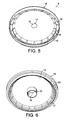
- the lid 8 is illustrated in figures 5 and 6 .
- the lid can take the form of a disc of plastic comprising a central portion 9 and a peripheral portion 10.
- the central portion can be substantially flat and may comprise a inlet port 11 for enabling the introduction of a water injection member of the beverage production device.
- the inlet port can extend by a tubular inlet portion 13 which serves for ensuring the water is guided toward the direction of the bottom of the body to ensure complete wetting of the substance in the enclosure and so reduced risk of leaving for example "dry powder spots".
- the inlet port is closed by a breakable or puncturable closure part 15. This part serves to prevent substance of the enclosure from filling the interstice between the upper surface of the lid and the sealing foil.
- the lid further comprises a peripheral portion 10 including a collecting recess 16.
- the collecting recess forms a U-shape in transversal section ( figure 3 ) which opens in the direction of the sealing foil.
- the recess is preferably continuously extending at the periphery of the lid although it can be replaced by several discontinuous recessed portions which may be separated by reinforcing elements or walls, for example.
- the collecting recess comprises an inner peripheral portion of wall 17 into which is provided a series of outlet openings 18 forming a fluid communication between the enclosure 14 and the collecting recess 16.
- the outlet openings also form a restriction in the flow of the centrifuged liquid in the enclosure.
- the centrifuged liquid is forced to pass the openings which can be sized as a function of the type of beverage to be produced. For instance, for espresso or ristretto coffee extract, it can be advantageous to provide smaller openings than for lungo or "Americano" coffee extract. For a same rotational speed, smaller openings create a higher resistance to the centrifuged liquid which remains longer in the capsule. As a consequence, the interaction between water and the coffee particles is higher and liquid can charge more in coffee solids.
- the openings may be slots or holes which are distributed at intervals in the inner peripheral portion of wall 17.
- the number of slots can range of from 5 to 200, preferably of from 10 to 100.
- These slots have preferably a width that is smaller than the statistical average size of the particles of the substance.
- the slots have a width of less than 500 microns for a substance which is ground coffee.
- the slots may extend if necessary on the central portion 9 or in the bottom of the recess 16.
- the slots can be replaced by holes of circular section having a diameter smaller than the statistical average size of the particles of the substance.
- the collecting recess 16 forms a peripheral groove of small depth, e.g., between 2 and 10 mm to allow the introduction of piercing members through the sealing foil to produce outlets for the brewed liquid which is produced in the capsule as will explained later in the description.
- the collecting recess 16 further comprises an outer peripheral portion 19 forming an edge bearing onto a seat portion 20 of the dished body.
- the outer portion 19 can be engaged in the seat portion 20 by a more or less tight fit engagement.
- An additional sealing portion 21 extending along the internal surface of the side wall of the body and in the direction of the bottom of the dished body can extend from the recess to create further sealing against possible ingress of liquid between the lid and the inner surface of the body of the capsule.
- the form of the collecting recessed means can take different configurations without departing from the scope of the invention.
- the recess 16 can be formed by the lid 8 and the side wall 7 of the dished body (as illustrated in figure 13 ).
- the outer peripheral portion 19 can be omitted.
- the series of outlet openings e.g., slots 18, are preferably placed at or close to the widening part of the enclosure relative to the central axis A. Therefore, the centrifuged liquid will tend to be guided along the inner surface of the side wall of the body, up to the inner side 12 of the lid, and then through the slots.
- the lid 8 is fully closed by the sealing foil 3 when it is sealed onto the rim of the dished body.
- the sealing foil could cover only the collecting recess including the region of the slots.
- the lid 8 can be a rigid or semi-rigid member made of thermoformed or injected plastic for instance.
- this part could also be made of a flexible membrane which is sealed to the inner surface of the dished body without departing from the scope of the invention.
- a filter wall can also be placed inside the enclosure against the inside surface 12 of the lid.
- a filter wall can provide an improved filtration, for example, for substance of very thin particle size and/or for delaying the release of the centrifuged liquid out of the enclosure by creating a higher pressure drop.
- a filter wall can be a paper filter or thin plastic film which is glued onto the surface 12 of the lid. The lid can be simply inserted in the dished shaped body or be fixed by any suitable connection means such as by ultrasonic welding.
- the system comprises a capsule 1 as aforementioned and a beverage preparation device 23.
- the device has a module 24 into which a capsule can be inserted.
- the capsule contains a food substance for being brewed and the capsule is removed from the module after use for being discarded (e.g., for waste or recycling of the organic and inorganic raw materials).
- the module 24 is in fluid communication with a water supply such as a water reservoir 25.
- a fluid transport means such as a pump 26 is provided in the fluid circuit 27 between the module and the water supply.
- a water heater 28 is further provided to heat water in the fluid circuit before water enters the module.
- the water heater can be inserted in the fluid circuit to heat fresh water coming from the reservoir or alternatively can be in the water reservoir that becomes a water boiler in such case.
- water can also be taken directly from a domestic water supply via a water plug connection.
- Water can be fed in the module 24 at low pressure or even at gravity pressure.
- a pressure of between 0 and 2 bar above atmospheric pressure can be envisaged at the water inlet of the module. Water at higher pressure than 2 bar could also be delivered if a pressure pump is utilized such a piston pump.
- the brewing module 24 can comprise two main capsule encasing sub-assemblies 29, 30; mainly comprising a water injection sub-assembly or water injection head and a liquid receiving subassembly including a capsule holder.
- the two subassemblies form positioning and centring means for the capsule in the device.
- the two assemblies' closes together to encase a capsule therein for example by a bayonet-type connection system 31.
- the liquid receiving subassembly 30 comprises a liquid duct 32, for example, protruding on a side of the subassembly for guiding the centrifuged liquid coming out of the capsule to a service receptacle such as a cup or glass.
- the liquid duct is in communication with a liquid receiver 33 forming a cylindrical wall placed at a short distance about a capsule holder formed by a rotating drum 34 into which the capsule is inserted as illustrated in figure 8 .
- the liquid receiver defines with the drum an intermediate cavity 63 for collecting the liquid as will be explained later in the description. Below the liquid receiving subassembly 30, are placed means for driving the capsule receiving drum 34 in rotation inside the subassembly.
- the driving means comprise preferably a rotary motor 40 which can be supplied by electricity or gas power.
- the water injection subassembly comprises a water inlet side comprising a water inlet 35 communicating upstream with the water fluid circuit 27.
- the rotary drum 34 is shaped as a hollow capsule holder with an internal cavity 36 complementary shaped to receive the capsule.
- the rotary drum 34 prolongs itself axially by a rotating shaft 37 which is maintained in rotational relationship relative to an outer base 38 of the liquid receiver 33 by a rotational guiding means 39 like a ball bearing or needle bearing. Therefore, the rotary drum is designed to rotate around a median axis I whereas the outer base 38 of the receiver is fixed relative to the device.
- the liquid receiver 33 can be fixed to a housing 43 of the motor by bolts 44 for example.
- a mechanical coupling 41 is placed at the interface between the rotating shaft 37 of the drum and the shaft 42 of the motor 40.
- the water injection subassembly 29 comprises a centrally arranged water injector 45 which is fixed relative to longitudinal axis I of the device.
- the water injector comprises a central tubular member 46 for transporting water from the inlet 35 to a water outlet 47 that is intended to protrude inside the enclosure 14 of the capsule.
- the water outlet is formed of a puncturing means 48 such as a sharp tubular tip that is able to create a puncture hole through the closing foil of the capsule and through the eventual breakable part of the tubular inlet 13 of the lid.
- the engaging part 49 has a central bore for receiving the water injector and rotational guiding means such as a ball or needle bearing 50 inserted between the part 49 and the injector 45.
- the engaging part further comprises outlet piercing members 51, 52, 53, 54 protruding from a disc-shaped engaging wall 55 of the part 49.
- the piercing members can be small cylindrical portions with a slanted cutting surface able to cut or perforate small holes in the sealing foil 3 of the capsule.
- the piercing members are arranged at the periphery of the wall 55, preferably evenly distributed to provide several openings in the capsule for the centrifuged liquid to leave the capsule forming several streams of liquid.
- the water injection subassembly 29 further comprises a valve system 56 for controlling the flow of liquid that is discharged from the device.
- the valve system 56 can be arranged on the capsule rotary engaging part 49 in the form of an annular engaging portion 57 which is biased under the force of elastic loading means 58 such as springs.
- the annular engaging portion 57 includes a pressing peripheral surface 59 which applies a closing force on the peripheral rim 4 of the capsule to be able to restrict the flow of liquid under the force of the elastic loading means.
- the surface 59 can form a cone or "V" for increasing the sealing pressure in a localized area.
- the engaging portion 57 further comprise an internal base portion 60.
- the elastic loading means 58 is thus inserted in a space located between the base portion 60 and a counter-force portion 61 of the engaging part 49. Therefore, at a rest position, the engaging portion 57 of the valve system keeps closing on the rim of the capsule under the compressive effect of the resilient means 58.
- the capsule engaging subassembly 29 may further comprise a tubular portion of skirt 62 which protrudes in the internal annular chamber 63 of the liquid receiving subassembly 30 when the two subassemblies are closed relatively one another about a capsule.
- This tubular portion of skirt 62 forms an impact wall for the centrifuged liquid under pressure that passes through the valve system.
- This portion 62 is preferably fixed on the subassembly 29.
- the subassembly further comprises a handling portion 64 for facilitating the connection on the liquid receiving subassembly 30.
- This handling portion 64 can have a knurled peripheral surface for handling.
- the handling portion can be fixed on the fixed base of the subassembly 29 by screws 67.
- This portion could of course be replaced by a lever mechanism or a similar handling means.
- connection means are provided for the relative connection of the two subassemblies 29, 30.
- small pins 65 are provided on the side of the tubular surface of the water injection subassembly 29 which can engage side locking openings 66 on the tubular surface of the liquid receiving subassembly 30. Therefore, connection between the two subassemblies can be carried out by a rotational angular or helical closure movement for enabling the pins to engage the oblong openings 66.
- other connection means can be envisaged to replace this bayonet-type connection means.
- a threading means or a translational closure means can be envisaged by any person skilled in the art.
- the capsule system of the invention works basically according to the following principle.
- the capsule device is opened by moving the two subassemblies 29, 30 relatively one another, e.g., by disconnecting the bayonet-type connection and separating the two subassemblies' 29, 30.
- a single-use sealed capsule 1 containing a food substance can inserted in the device, i.e., placed in the cavity of the rotating drum 36.
- the capsule can be placed in the device while the capsule being gastight closed by the sealing foil 3.
- the device is then closed by the subassembly 29 being connected back onto the subassembly 30 and locked by the connection means.
- the capsule In the locked position, the capsule is opened by the water injector that pierces through the sealing foil of the capsule and introducing itself through the water inlet 35 of the capsule. At the same time, several liquid outlets are pierced at the periphery of the sealing foil by the outlet piercing members 51-54. Water can thus be introduced in the capsule via the central water injector 45. Venting holes can be produced in the injection subassemblies to allow gas to escape the capsule while water is introduced in.
- the capsule can be driven in rotation by activating the rotary motor 40. The start of the centrifugal operation can be carried out at the same time as water injection start being introduced in the capsule or slightly after or before this water injection operation starts.
- the centrifugation is carried out by rotating the capsule around the central axis I of rotation of the device that is preferably aligned to the central axis A of the capsule.
- the rotational speed is preferably of from 1000 to 12000 round-per-minutes (rpm), more preferably of from 1500 to 8000 rpm.
- a control unit can be provided in the device for setting the rotational speed according to the nature of the liquid to be brewed and/or the substance in the capsule.
- the substance such as coffee powder
- the centrifugal forces exert themselves uniformly on the mass of the substance. Consequently, the water distribution is also more uniform compared to usual methods using a pressure pump to exert the pressure in the capsule.
- there is lower risk of preferential flow path through the substance which could lead to areas which are not properly wetted and so not properly brewed, dispersed or dissolved.
- ground coffee powder the liquid that reaches the internal sidewall of the capsule is a liquid extract. This liquid extract is then forced to flow upwards along the internal surface of the sidewall of the capsule. The widening of the sidewall 7 of the capsule promotes the upward flow of the liquid in the capsule in direction of the openings.
- outlet openings 18 of the enclosure of the capsule are sized as a function of the substance stored in the capsule.
- Small openings such as slots of small width or holes of small diameter tend to provide a filtering function to retain the solid particles in the enclosure of the capsule while allowing only the liquid extract to pass the openings.
- the openings may also provide a flow restriction that impacts on the interaction of water with the substance and on the creation of foam or crema on the top of the beverage. These holes also form sufficient restrictions that create shear forces and consequently generate foam or coffee crema.
- Some gas contained in the capsule can become entrapped in the liquid and forms, due to the pressure release after the flow restriction, a multitude of small bubbles in the liquid.
- valve system 56 of the device can start opening as pressure of liquid increases on the valve when leaving the capsule. Therefore, a certain time delay before opening can be controlled by the valve system to enable sufficient interaction between water and the substance contained in the capsule. This controlled delay depends on various parameters such as the centrifugal speed, the force exerted by the elastic loading means (i.e., spring stiffness), the pressure drop as created by the substance and outlet openings, etc.
- the opening of the valve system occurs by the pressing surface 59 of the valve system lifting as pressure of liquid increases on its internal surface. It can be noted that the capsule of the rim can also be substantially flexible to flex under the effect of the pressure of liquid.
- the relative movement between the pressing surface and the capsule create a small passage for the liquid to escape out of the small interstice upstream of the valve system.
- a jet of liquid can be formed that impacts on the internal surface of the portion of skirt 62. The liquid starts to fill the cavity 68 of the liquid receiving subassembly and liquid can drain through the liquid duct 32 to be collected in a cup or glass placed underneath.
- the valve system 56 differs in that the elastic loading means is obtained by a rubber elastic O-ring 69 inserting between a pinching surface 59 and a fixed portion 61 of the water injection subassembly 29.
- the O-ring is maintained between two concave portions 70, 71 of the valve system.
- the pinching surface can be shaped with a sharp tip or edge that can create a concentration of forces on the rim.
- the elastic loading means and the pinching portion are the same element.
- the pinching portion can be made of rubber-elastic material.
- the water injector can be a simple water inlet in the capsule with no puncture means.
- the capsule is pre-opened before it is inserted in the device, i.e., the sealing foil is removed by peeling, or a central hole is perforated before the capsule is inserted in the device.
- a sealing engagement of the water injector can be performed by a sealing means 72 which applies a certain sealing pressure on the top surface of the capsule. Therefore, water is prevented from leaking along the top surface of the capsule and from by-passing the capsule to release directly through the liquid outlet.
- the capsule of the invention can take various embodiments such as the one illustrated in figures 14 and 15 .
- the general structure of the capsule is the same as for the previous embodiment except that the outlet openings are formed by a filter paper, a woven or non-woven portion or another meshed or porous membrane 72.
- the lid 8 which is inserted in the dished body 2 comprises a circumferential band of a porous material.
- the porous material provides restriction of the flow, creating a certain pressure drop, e.g., between 0.5 and 4 bar, and leading to a filtering of the solid particles.
- the size of the pores of the material can be chosen to retain also the coffee fines, i.e., the particles of particle size as low as 90 microns.
- the pressure drop is also obtained when the overall open surface of the porous band is lower than 50% of the total surface area of the surface of the band.
- the paper, fabric, meshed or porous material can be formed of a band or bands which can be welded or otherwise combined to the lid.
- the recess 16 can be filled by a porous compressible material to provide a filtering function as well.
- the material could be sponge or fabric.
- the capsule in the system of the invention may also comprise an enclosure which is formed of a dished body 2 and a porous wall 80.
- the dished body comprises a main cavity 82 for storing the food substance and a peripheral recess 81 for receiving the liquid extract that traverses the porous wall 80 during the centrifugation process.
- the recess 81 is delimited by an inner edge 83 and an outer rim 84 .
- the porous wall 80 can be attached to an inner edge 83 of the recess 81.
- a gastight foil membrane 86 is preferably attached onto the outer rim 84 of the body.
- the inner edge is preferably placed below the outer rim in order to let a free space 85 between porous wall 80 and the foil membrane 86.
- the porous wall can be sealed by heat or ultrasonic welding onto the inner edge 83.
- the porous wall 80 can have openings (i.e., pores) along its whole surface or along a peripheral portion of wall only.
- Figure 16 shows a portion of the wall 87 which normally have the openings whereas the central portion 88 is free of openings.
- the pressure is dependent on various factors, in particular, the rotating speed of the capsule in the device, the radius at the peripheral portion of wall 87 (specially, determining the relative centrifugal force "g" at the portion 87) and the size of the openings.
- the size of the openings is preferably comprised between 1 and 600 microns. More preferably, the size of the openings is comprised between 10 and 200 microns forming a flow restriction means which creates a certain drop of pressure during the centrifugation of the capsule along its central axis.
- the overall surface area of the pores of the porous wall should be lower than 50% of the total surface area of said wall, most preferably lower than 40%.
- the capsule of figures 16 and 17 can be pierced in its centre 89 for injecting water in the enclosure 82 containing the substance. As a result both the outer foil 86 and the inner wall 80 are pierced.
- the capsule is inserted in a device as described before.
- the capsule is driven in centrifugal rotation at a determined speed, e.g., between 1000 and 16000 rpm, more preferably between 5000 and 12000 rpm.
- the brewing or dissolution process takes place in the enclosure by water traversing the substance.
- the food liquid traverses the porous portion of wall 87, (eventually also part of the portion 88 if porous) and leaves the enclosure via the interspace 85 then via the annular recess 81.
- the liquid is allowed to leave the capsule via pierced holes made in the foil above the recess 81.
- Figure 18 shows a similar capsule but with the inner porous wall 80 comprising a central portion 880 which is sealed to the external gastight foil 86 and a peripheral portion 870 which is distant from the foil 86.
- the peripheral portion 870 comprises the outlet openings of the enclosure.
- the central portion 880 may have openings or may be free of openings. In this embodiment, no liquid is allowed to go between the outer foil 86 and the inner portion of wall 880 since both are sealed together. If a sufficient pressure drop is created at the portions of wall 870 in the capsule, the device may not necessarily be provided with an additional flow restriction means such as the valve described previously.
- the flow restriction means in the capsule suffices to maintain a sufficient pressure in the enclosure and so obtain a good interaction between the substance, e.g., ground coffee and water.
- good espresso-type coffee with crema can be produced with a capsule comprising a woven polymer membrane comprising pores within a range of between 10 to 200 microns.
- peripheral portion of the capsule comprising the restriction means can be substantially oriented perpendicularly to the axis of rotation as in the examples of figures 16 to 18 or inclined relative to said axis as in the example of figures 1 to 6 .
- the flow restriction can be obtained or complemented by chicanes in the capsule and/or in the device or a similar structure forming a tortuous flow path for the liquid.
- the system capsule of the invention provide remarkable brewing results with solid contents which are higher than with usual systems.
- the results are very reproducible from capsule to capsule.
- crema is also remarkably improved with a creamier, more stable and thicker texture.
- the pressure drop of the restriction means can be measured by a pressure measurement test consisting of filling water under pressure in the capsule and measuring the pressure of water at the injection point at which liquid is allowed to pass the restriction means, i.e., the valve system.
Abstract
Description
- The present invention relates to a device and capsule system for preparing a food liquid from a food substance contained in a receptacle by passing water through the substance using centrifugal forces.
- It is known to prepare beverages wherein a mixture consisting of brewed coffee and coffee powder is separated with centrifugal forces. Such a mixture is obtained by bringing hot water and coffee powder together for a defined time. The water is then forced through a screen, on which screen powder material is present.
- Existing systems consist of placing the coffee powder in a receptacle which is usually a non-removable part of a machine such as in
EP 0367 600B1 . Such devices have many disadvantages. Firstly, the coffee powder must be properly dosed manually in the receptacle. Secondly, the centrifuged coffee waste becomes dry and it must be removed by scraping the surface of the receptacle. As a result, the coffee preparation requires a lot of manual handling and is so very time consuming. Usually coffee freshness can also vary a lot and this can impact on the cup quality because coffee comes generally from bulk package or coffee is ground from beans in the receptacle itself. - Also, depending on the manual dosage of coffee and the brewing conditions (e.g., centrifugal speed, receptacle size) the cup quality can vary a lot.
- Therefore, these systems have never reached an important commercial success.
- In German patent application
DE 102005007852 , the machine comprises a removable holder into which an open cup-shaped part of the receptacle is placed; the other part or lid being attached to a driving axis of the machine. However, a disadvantage is the intensive manual handling. Another disadvantage is the difficulty to control quality of the coffee due to a lack of control for the dosing of the powder and a lack of control of the freshness of the coffee powder. - Other devices for brewing coffee by centrifuge forces are described in
WO 2006/112691 ;FR2624364 EP0367600 ;GB2253336 FR2686007 EP0749713 ;DE4240429 ;EP0651963 ;FR2726988 DE4439252 ;EP0367600 ;FR2132310 FR2513106 FR2487661 DE3529053 ;FR2535597 WO2007/041954 ;DE3529204 ;DE3719962 ;FR2685186 DE3241606 andUS-A-4545296 . - In particular,
US-A-5566605 discloses an extraction cell of the centrifugal type for a hot beverage preparation machine having a drum and a cover and sealing and filtration means constituted by at least one deformable seal. - However, the effect of centrifugal forces to brew coffee or prepare other food substances presents many advantages compared to the normal brewing methods using pressure pumps. For example, in "espresso" coffee-type brewing methods, it is very difficult to master all the parameters which influence the quality of extraction of the delivered coffee extract. These parameters are typically the pressure, the flow rate which decreases with the pressure, the compaction of the coffee powder which also influences the flow characteristics and which depends on the coffee ground particle size, the temperature, the water flow distribution and so on.
- Therefore, there is a need for proposing a new capsule system and a method adapted therefore for which the extraction parameters can be better and more independently controlled and therefore can be better mastered for controlling quality of the delivered food liquid.
- At the same time, there is a need for a way of preparing a food liquid which is more convenient compared to the prior art centrifugal coffee preparation devices and which provides a better in-cup quality with a higher control of important quality parameters such as freshness and accurate dosage of the substance in the receptacle.
- Therefore, the invention relates to a liquid food preparation device for preparing a liquid food from a food substance contained in a single-use capsule, removably insertable in the device, by passing water through the substance in the capsule, comprising a water injection head in the capsule and a capsule holder for holding the capsule in the device,
characterized in that it comprises: - a water injector, as part of the water injection head, arranged for introducing water along a central axis relative to the capsule holder,
- means for driving the capsule holder in centrifugation around an axis of rotation (I) aligned with said central axis of the capsule holder and,
- at least one opening means for providing at least one liquid delivery outlet in the capsule; said opening means being placed in a position relatively offset to said central axis of the capsule holder.
- In a mode, the said opening means for providing the liquid delivery outlet(s) is at least one piercing member and/or cutting member and/or burning member.
- More particularly, the water injecting head comprises a non-moving water injector and a rotary engaging member for engaging the capsule in closure onto the capsule holder. The engaging member thus rotates in conjunction with the capsule holder during centrifugation of the capsule in the device.
- In one mode, the opening means of the liquid delivery outlet(s), e.g., piercing members or other means, can be part of the rotary engaging member of the water injection head.
- In an alternative possible configuration, the opening means of the liquid delivery, e.g., piercing members or other means, can be part of the capsule holder.
- In a mode, the opening means comprises a series of opening means, e.g., piercing members or other means, distributed along a substantially circular path about the central axis.
- The opening means, e.g., piercing members, engages the capsule in such a way that the rotational momentum can be transmitted from the device to the capsule.
- In a first mode, the opening members, e.g. piercing members, can be arranged in the device in such a manner to pierce the outlet(s) of the capsule during closure of the device about the capsule. In particular, the opening members are mounted on the rotary engaging member or capsule holder to open the capsule, e.g., pierce the liquid inlet(s) in the capsule, during relative engagement or closure of the rotary engaging member and the capsule holder about the capsule. For instance, piercing members are placed sufficiently in relief relative to the surface of the water injection head to pierce the capsule when the head approaches and engages the capsule in closure. Preferably, the series of piercing members comprises at least four members for forming at least four small liquid delivery outlets at the periphery of the capsule. The piercing members can be distributed at 90-degree intervals therefore providing a homogeneous liquid delivery at the periphery of the capsule.
- The piercing members can engage the capsule and so participate to transfer the rotational momentum to the capsule during rotation.
- In another mode, the opening members are configured to create the liquid delivery outlet(s) of the capsule after a certain quantity of water is filled in the capsule.
- The capsule may comprise a perforable membrane made of an aluminium and/or polymer materials. In particular, the puncturable membrane can have a thickness between 10 and 200 microns.
- In a possible aspect of the invention, the water injector also comprises an opening means such as a piercing member. The opening means can be a piercing member arranged as a hollow piercing tube for injecting water in the centre of the capsule.
- The piercing member of the water injector has a diameter of less than 5 mm, preferably, between 0.9 and 2.9 mm. Indeed, the pressure in the capsule increases from the centre to the periphery. The pressure of water in the centre can be close to zero but can gradually increase outwardly. Therefore, a small diameter of the injector provides a small inlet in the capsule to reduce the pressure at the inlet side of the capsule.
- The driving means of the capsule holder can be directly connected to the capsule holder or indirectly connected to the capsule holder. A direct connection to the capsule holder can be obtained by a rotational drive assembly comprising a rotary motor and a drive transmission connecting the motor to the bottom of the capsule holder. The drive transmission may comprise a suitable gear reduction or amplification to provide the correct transmission rate to the capsule holder in function of the motor speed. An indirect connection to the capsule holder can be obtained by transmission of the rotational momentum from the water injection head to the capsule holder. In this case, the drive transmission of the rotational drive assembly is connected directly to the upper side of the water injection head, in particular to the rotary engaging member of the head.
- The device of the invention may receive capsules made of rigid, semi-rigid and/or soft materials. The capsule may be made of materials such as plastics, aluminium, cellulose-based materials or other biodegradable materials, and combinations therefore. Preferably, the capsule has a peripheral wall made of a pierceable membrane. The membrane can form a sealing lid covering a cup-shaped body which receives the food substance to be brewed.
- In a mode, a valve means is arranged downstream of the opening means of the at least one liquid delivery outlet of the capsule. The valve means may comprise an annular closure ring and an elastic means for elastically engaging the ring in closure onto a peripheral part, e.g., an edge, of the capsule.
- The invention also relates to a method for preparing a food liquid from a food substance contained in a single-use capsule by passing water through the substance comprising:
- driving the capsule in centrifugal rotation while introducing water in the centre of capsule,
- passing water through the substance to form a food liquid,
- opening at least one liquid delivery outlet in the capsule which is peripherally offset relative to the centre of the capsule and delivering said liquid from said at least one liquid delivery outlet.
- In a possible aspect of the method, the at least one liquid delivery outlet is obtained by piercing the capsule in the device. Thus, the capsule can be a gas tightly sealed capsule comprising ingredients such as ground coffee, instant coffee, leaf tea, cocoa, chocolate, a creamer, sweetener, and combinations thereof which can be preserved in protected atmosphere conditions for an extended period of time. The capsule is thus opened at the time of use in the device.
- According to an aspect of the method, at least one liquid delivery outlet is obtained by piercing a sealing membrane of the capsule. The membrane can be formed of plastic and/or metal material.
- In a mode of the invention, the at least one inlet opening is carried out by mechanical piercing effect of the capsule, e.g., with an external piercing means of the device being displaced relatively to the capsule.
- In this case, piercing is carried out when the capsule is inserted in the device such as by effect of the device closing about the capsule.
- According to the method, water is introduced in the capsule through an opening of less than 5 mm, preferably between 0.9 and 2.9 mm. As aforementioned, a sufficiently small water inlet is preferred in the capsule in order to reduce the internal pressure of liquid at the inlet side of the capsule and therefore avoid leakage problems.
- Preferably, water is introduced in the centre of the capsule after having pierced a water inlet in the centre of the capsule.
- According to an aspect of the invention, the food liquid delivered from the capsule is passed via a flow restriction means. The flow restriction means can be configured for providing a pressure drop of at least 0.5 bar of relative pressure during centrifugation. Preferably, the flow restriction means is configured for providing a pressure drop of between 1 and 6 bar, most preferably between 1.5 and 4 bar, of relative pressure during centrifugation. A flow restriction within the flow path of the centrifuged liquid enables to control the release of the centrifuged liquid for improving the interaction of water with the substance within the capsule as well as providing eventually foam to the liquid by the pressure release and the shear stresses which are created at the restriction. More particularly, the flow restriction means enables to maintain a pressure of several bars at the periphery of the enclosure and to retard the release of the liquid.
- More particularly, the liquid delivered from the capsule opens a valve for opening when a certain pressure is exerted on the valve by the centrifuged liquid. The valve also regulates the flow of liquid and it reduces the risk of blocking the small outlets provided in the capsule by small size particles, e.g., coffee fines, in particular, at relatively low pressure values.
- The valve can be part of the capsule or can be part of the device.
- As a result, the system of the invention provides a solution for preparing a food liquid wherein a controlled release of the food liquid can be carried out. For example, the release of liquid can be delayed until a certain pressure is exerted on the valve means. A delayed opening of the valve means enables to improve the interaction between water and the substance contained in the capsule and reduces the risk of the flow blocking in the capsule.
- For coffee, for example, it may be advantageous to optimize interaction of water and the ground coffee particles to obtain a good extraction of the coffee and aroma compounds. Moreover, the valve means provides a restriction which may improve the creation of foam or coffee crema.
- The valve means can be formed by at least one engaging portion of the device which moves relatively to an engaging portion of the capsule under the effect of the pressurized liquid for making a thin annular laminating passage for the liquid. The laminating passage also enables to create a liquid jet of relatively high velocity that impacts on a wall of the device. As a result, a relatively high amount of foam can be created both due to the restriction that is created by the valve means and by the impact of the liquid on the impact surface of the device at a relatively high velocity during centrifugation. Depending on the amount of pressure exerted on the valve means by the centrifuged liquid, the restriction caused by the valve means can differ in amplitude.
- In a possible mode, the valve means can be calibrated or adjusted to selectively open a liquid passage through the device at a threshold of pressure in the capsule.
- The liquid delivered from the capsule can also be filtered by filtering means provided in the capsule. Such a configuration has many advantages because the device is simplified, the filter does not require cleaning since it is discarded with the capsule. The term "food liquid" has here a broad meaning and encompasses: a culinary liquid such as soup or sauce, a beverage liquid such as coffee extract (obtained from ground and/or instant coffee powder), liquid chocolate, milk (obtained from powder and/or liquid concentrate), tea extract (obtained from instant and/or leaf), etc., or a nutritional liquid such as an infant formula and combinations thereof.
- The terms "brewing" or "brewed" is not to be taken in the narrow sense of extracting under pressure a liquid from a non-entirely soluble substance (such as ground coffee or leaf tea) but is to be taken in a broader sense as encompassing the interaction processes of a food substance and a liquid, preferably water, including the processes of extraction, infusion, adsorption, dissolution, dilution, dispersion, mixing, emulsifying, foaming and the like.
- The term "piercing" is to be taken in its broad sense and it includes the mechanical and/or thermal processing for providing a through-opening in a wall of the capsule.
- Additional features of the invention will appear in the detailed description of the figures which follows.
-
Figure 1 is a perspective view from above of a capsule of the invention; -
Figure 2 is a perspective view from below of the capsule of the invention; -
Figure 3 is perspective view of the capsule with the sealing foil removed; -
Figure 4 is a cross section view of the capsule of the invention; -
Figure 5 is a perspective view of the lid from above of the capsule of the invention; -
Figure 6 is a perspective view of the lid from below of the capsule offigure 4 ; -
Figure 7 is a perspective view of the beverage production device of the invention; -
Figure 8 is a perspective view of the beverage production module in open mode; -
Figure 9 is a cross-sectional view along line A-A of the beverage production module in a closed mode about the capsule; -
Figure 10 is an enlarged view of the view offigure 9 ; -
Figure 11 is a view of the water injection assembly of the module offigures 9 and10 ; -
Figure 12 is a cross sectional view of a beverage production module similar tofigure 9 but for another embodiment of the invention; -
Figure 13 is a detail view of the module offigure 12 ; -
Figure 14 is a cross section view of a variant of the capsule of the invention; -
Figure 15 is a view from underside of the lid of the capsule offigure 14 ; -
Figure 16 is a perspective cross sectional view of a capsule according to another mode of the invention; -
Figure 17 is a cross sectional view of the capsule offigure 16 ; -
Figure 18 is a cross sectional view of a capsule according to still another mode. - As shown in
figures 1 and 2 , apreferred capsule 1 of the invention generally comprises a dishedbody 2 onto which is sealed a sealingfoil 3. The sealingfoil 3 is sealed onto a peripheral rim 4 of the body at a sealingannular portion 5. The rim 4 can extend outwards forming a small annular portion, e.g., of about 2-5 mm. The dished body comprises abottom wall 6 and aside wall 7 which preferably widens in direction of the large open end of the body opposed to the bottom wall. The dished body is preferably rigid or semi-rigid. It can be formed of a food grade plastics, e.g., polypropylene, with a gas barrier layer such as EVOH and the like or aluminium alloy or a complex of plastic and aluminium alloy. The sealingfoil 3 can be made of a thinner material such as a plastic laminate also including a barrier layer or aluminium alloy or a combination of plastic and aluminium alloy. The sealing foil is usually of a thickness between 50 and 250 microns, for example. The sealing foil member can be pierced for creating the water inlet and the beverage outlet(s) as will be described later in the description. - In relation to the embodiment of
figures 3 to 6 , the capsule of the invention comprises an inner member forming alid 8 which is inserted in the dished body. Thelid 8 andbody 2 delimit together aninternal enclosure 14 for receiving thefood substance 22. Preferably, the capsule forms a symmetry of revolution around a central axis A. However, it should be noted that the capsule may not necessarily have a circular section around axis A but may take another form such as a square or a polygonal form. Thelid 8 is illustrated infigures 5 and 6 . The lid can take the form of a disc of plastic comprising acentral portion 9 and aperipheral portion 10. The central portion can be substantially flat and may comprise ainlet port 11 for enabling the introduction of a water injection member of the beverage production device. In theinternal side 12 of the lid, the inlet port can extend by atubular inlet portion 13 which serves for ensuring the water is guided toward the direction of the bottom of the body to ensure complete wetting of the substance in the enclosure and so reduced risk of leaving for example "dry powder spots". Preferably, the inlet port is closed by a breakable orpuncturable closure part 15. This part serves to prevent substance of the enclosure from filling the interstice between the upper surface of the lid and the sealing foil. The lid further comprises aperipheral portion 10 including a collectingrecess 16. The collecting recess forms a U-shape in transversal section (figure 3 ) which opens in the direction of the sealing foil. The recess is preferably continuously extending at the periphery of the lid although it can be replaced by several discontinuous recessed portions which may be separated by reinforcing elements or walls, for example. The collecting recess comprises an inner peripheral portion ofwall 17 into which is provided a series ofoutlet openings 18 forming a fluid communication between theenclosure 14 and the collectingrecess 16. - The outlet openings also form a restriction in the flow of the centrifuged liquid in the enclosure. The centrifuged liquid is forced to pass the openings which can be sized as a function of the type of beverage to be produced. For instance, for espresso or ristretto coffee extract, it can be advantageous to provide smaller openings than for lungo or "Americano" coffee extract. For a same rotational speed, smaller openings create a higher resistance to the centrifuged liquid which remains longer in the capsule. As a consequence, the interaction between water and the coffee particles is higher and liquid can charge more in coffee solids.
- As illustrated in this example, the openings may be slots or holes which are distributed at intervals in the inner peripheral portion of
wall 17. For example, the number of slots can range of from 5 to 200, preferably of from 10 to 100. These slots have preferably a width that is smaller than the statistical average size of the particles of the substance. For example, the slots have a width of less than 500 microns for a substance which is ground coffee. The slots may extend if necessary on thecentral portion 9 or in the bottom of therecess 16. The slots can be replaced by holes of circular section having a diameter smaller than the statistical average size of the particles of the substance. - The collecting
recess 16 forms a peripheral groove of small depth, e.g., between 2 and 10 mm to allow the introduction of piercing members through the sealing foil to produce outlets for the brewed liquid which is produced in the capsule as will explained later in the description. The collectingrecess 16 further comprises an outerperipheral portion 19 forming an edge bearing onto aseat portion 20 of the dished body. Theouter portion 19 can be engaged in theseat portion 20 by a more or less tight fit engagement. An additional sealingportion 21 extending along the internal surface of the side wall of the body and in the direction of the bottom of the dished body can extend from the recess to create further sealing against possible ingress of liquid between the lid and the inner surface of the body of the capsule. Of course, the form of the collecting recessed means can take different configurations without departing from the scope of the invention. For example, therecess 16 can be formed by thelid 8 and theside wall 7 of the dished body (as illustrated infigure 13 ). In this case, the outerperipheral portion 19 can be omitted. - As illustrated in the figures, the series of outlet openings, e.g.,
slots 18, are preferably placed at or close to the widening part of the enclosure relative to the central axis A. Therefore, the centrifuged liquid will tend to be guided along the inner surface of the side wall of the body, up to theinner side 12 of the lid, and then through the slots. Thelid 8 is fully closed by the sealingfoil 3 when it is sealed onto the rim of the dished body. In a possible alternative, the sealing foil could cover only the collecting recess including the region of the slots. - It should be noticed that the
lid 8 can be a rigid or semi-rigid member made of thermoformed or injected plastic for instance. However, this part could also be made of a flexible membrane which is sealed to the inner surface of the dished body without departing from the scope of the invention. - It can also be noticed that a filter wall can also be placed inside the enclosure against the
inside surface 12 of the lid. A filter wall can provide an improved filtration, for example, for substance of very thin particle size and/or for delaying the release of the centrifuged liquid out of the enclosure by creating a higher pressure drop. A filter wall can be a paper filter or thin plastic film which is glued onto thesurface 12 of the lid. The lid can be simply inserted in the dished shaped body or be fixed by any suitable connection means such as by ultrasonic welding. - The system including a capsule of the invention and a beverage preparation device is illustrated in
figures 7 and8 and described now. - Thus, the system comprises a
capsule 1 as aforementioned and abeverage preparation device 23. The device has amodule 24 into which a capsule can be inserted. The capsule contains a food substance for being brewed and the capsule is removed from the module after use for being discarded (e.g., for waste or recycling of the organic and inorganic raw materials). Themodule 24 is in fluid communication with a water supply such as awater reservoir 25. A fluid transport means such as apump 26 is provided in thefluid circuit 27 between the module and the water supply. Awater heater 28 is further provided to heat water in the fluid circuit before water enters the module. The water heater can be inserted in the fluid circuit to heat fresh water coming from the reservoir or alternatively can be in the water reservoir that becomes a water boiler in such case. Of course, water can also be taken directly from a domestic water supply via a water plug connection. - Water can be fed in the
module 24 at low pressure or even at gravity pressure. For example, a pressure of between 0 and 2 bar above atmospheric pressure can be envisaged at the water inlet of the module. Water at higher pressure than 2 bar could also be delivered if a pressure pump is utilized such a piston pump. - The
brewing module 24 can comprise two maincapsule encasing sub-assemblies - The two assemblies' closes together to encase a capsule therein for example by a bayonet-
type connection system 31. Theliquid receiving subassembly 30 comprises aliquid duct 32, for example, protruding on a side of the subassembly for guiding the centrifuged liquid coming out of the capsule to a service receptacle such as a cup or glass. The liquid duct is in communication with aliquid receiver 33 forming a cylindrical wall placed at a short distance about a capsule holder formed by arotating drum 34 into which the capsule is inserted as illustrated infigure 8 . The liquid receiver defines with the drum anintermediate cavity 63 for collecting the liquid as will be explained later in the description. Below theliquid receiving subassembly 30, are placed means for driving thecapsule receiving drum 34 in rotation inside the subassembly. - The driving means comprise preferably a
rotary motor 40 which can be supplied by electricity or gas power. - The water injection subassembly comprises a water inlet side comprising a
water inlet 35 communicating upstream with thewater fluid circuit 27. - In relation to
figures 9 and10 , therotary drum 34 is shaped as a hollow capsule holder with aninternal cavity 36 complementary shaped to receive the capsule. Therotary drum 34 prolongs itself axially by a rotatingshaft 37 which is maintained in rotational relationship relative to anouter base 38 of theliquid receiver 33 by a rotational guiding means 39 like a ball bearing or needle bearing. Therefore, the rotary drum is designed to rotate around a median axis I whereas theouter base 38 of the receiver is fixed relative to the device. Theliquid receiver 33 can be fixed to ahousing 43 of the motor bybolts 44 for example. Amechanical coupling 41 is placed at the interface between therotating shaft 37 of the drum and theshaft 42 of themotor 40. - Considering the
water injection subassembly 29, as illustrated infigures 10 and11 , it comprises a centrally arrangedwater injector 45 which is fixed relative to longitudinal axis I of the device. The water injector comprises acentral tubular member 46 for transporting water from theinlet 35 to awater outlet 47 that is intended to protrude inside theenclosure 14 of the capsule. The water outlet is formed of a puncturing means 48 such as a sharp tubular tip that is able to create a puncture hole through the closing foil of the capsule and through the eventual breakable part of thetubular inlet 13 of the lid. - About the water injector is mounted a capsule
rotary engaging part 49. The engagingpart 49 has a central bore for receiving the water injector and rotational guiding means such as a ball orneedle bearing 50 inserted between thepart 49 and theinjector 45. The engaging part further comprisesoutlet piercing members wall 55 of thepart 49. The piercing members can be small cylindrical portions with a slanted cutting surface able to cut or perforate small holes in the sealingfoil 3 of the capsule. The piercing members are arranged at the periphery of thewall 55, preferably evenly distributed to provide several openings in the capsule for the centrifuged liquid to leave the capsule forming several streams of liquid. - According to one aspect of the invention, the
water injection subassembly 29 further comprises avalve system 56 for controlling the flow of liquid that is discharged from the device. Thevalve system 56 can be arranged on the capsulerotary engaging part 49 in the form of an annular engagingportion 57 which is biased under the force of elastic loading means 58 such as springs. The annular engagingportion 57 includes a pressingperipheral surface 59 which applies a closing force on the peripheral rim 4 of the capsule to be able to restrict the flow of liquid under the force of the elastic loading means. Thesurface 59 can form a cone or "V" for increasing the sealing pressure in a localized area. The engagingportion 57 further comprise aninternal base portion 60. The elastic loading means 58 is thus inserted in a space located between thebase portion 60 and acounter-force portion 61 of theengaging part 49. Therefore, at a rest position, the engagingportion 57 of the valve system keeps closing on the rim of the capsule under the compressive effect of theresilient means 58. - The
capsule engaging subassembly 29 may further comprise a tubular portion ofskirt 62 which protrudes in the internalannular chamber 63 of theliquid receiving subassembly 30 when the two subassemblies are closed relatively one another about a capsule. This tubular portion ofskirt 62 forms an impact wall for the centrifuged liquid under pressure that passes through the valve system. Thisportion 62 is preferably fixed on thesubassembly 29. The subassembly further comprises a handlingportion 64 for facilitating the connection on theliquid receiving subassembly 30. This handlingportion 64 can have a knurled peripheral surface for handling. The handling portion can be fixed on the fixed base of thesubassembly 29 byscrews 67. - This portion could of course be replaced by a lever mechanism or a similar handling means.
- As already mentioned, connection means are provided for the relative connection of the two
subassemblies small pins 65 are provided on the side of the tubular surface of thewater injection subassembly 29 which can engageside locking openings 66 on the tubular surface of theliquid receiving subassembly 30. Therefore, connection between the two subassemblies can be carried out by a rotational angular or helical closure movement for enabling the pins to engage theoblong openings 66. Of course, other connection means can be envisaged to replace this bayonet-type connection means. For instance, a threading means or a translational closure means can be envisaged by any person skilled in the art. - The capsule system of the invention works basically according to the following principle. The capsule device is opened by moving the two
subassemblies capsule 1 containing a food substance can inserted in the device, i.e., placed in the cavity of therotating drum 36. The capsule can be placed in the device while the capsule being gastight closed by the sealingfoil 3. The device is then closed by thesubassembly 29 being connected back onto thesubassembly 30 and locked by the connection means. In the locked position, the capsule is opened by the water injector that pierces through the sealing foil of the capsule and introducing itself through thewater inlet 35 of the capsule. At the same time, several liquid outlets are pierced at the periphery of the sealing foil by the outlet piercing members 51-54. Water can thus be introduced in the capsule via thecentral water injector 45. Venting holes can be produced in the injection subassemblies to allow gas to escape the capsule while water is introduced in. The capsule can be driven in rotation by activating therotary motor 40. The start of the centrifugal operation can be carried out at the same time as water injection start being introduced in the capsule or slightly after or before this water injection operation starts. - For instance, it might be advantageous for brewing ground coffee, to allow during several seconds that water fills in the capsule before starting the centrifugal operation by rotating the capsule. Thus, water can properly infiltrate in the coffee before, the liquid is centrifuged thereby avoiding coffee area to remain dry in the coffee portion. The centrifugation is carried out by rotating the capsule around the central axis I of rotation of the device that is preferably aligned to the central axis A of the capsule. The rotational speed is preferably of from 1000 to 12000 round-per-minutes (rpm), more preferably of from 1500 to 8000 rpm. A control unit can be provided in the device for setting the rotational speed according to the nature of the liquid to be brewed and/or the substance in the capsule. The higher the rotational speed, the higher the pressure is exerted at the peripheral wall of the capsule and the more substance is compacted on the sidewall of the capsule. It is important to notice that higher rotational speeds promote brewing of coffee extract containing a lower solid content since the residence time of liquid in the coffee bed is shorter. Lower rotational speeds provide coffee of higher strength (coffee solid content) since the residence time of liquid in the capsule is longer. Brewing takes place in the capsule by water traversing the substance thereby providing an extraction or partial or total dispersion or dissolution of the substance. As a result, a centrifuged liquid is allowed to pass through the plurality of
outlet openings 18 provided in the capsule, e.g., through thelid 8. - Under the effect of centrifugal forces, the substance, such as coffee powder, tends to compact itself radially against the
peripheral walls sidewall 7 of the capsule promotes the upward flow of the liquid in the capsule in direction of the openings. - These
outlet openings 18 of the enclosure of the capsule are sized as a function of the substance stored in the capsule. Small openings such as slots of small width or holes of small diameter tend to provide a filtering function to retain the solid particles in the enclosure of the capsule while allowing only the liquid extract to pass the openings. Also as aforementioned, the openings may also provide a flow restriction that impacts on the interaction of water with the substance and on the creation of foam or crema on the top of the beverage. These holes also form sufficient restrictions that create shear forces and consequently generate foam or coffee crema. Some gas contained in the capsule can become entrapped in the liquid and forms, due to the pressure release after the flow restriction, a multitude of small bubbles in the liquid. - Also, the
valve system 56 of the device can start opening as pressure of liquid increases on the valve when leaving the capsule. Therefore, a certain time delay before opening can be controlled by the valve system to enable sufficient interaction between water and the substance contained in the capsule. This controlled delay depends on various parameters such as the centrifugal speed, the force exerted by the elastic loading means (i.e., spring stiffness), the pressure drop as created by the substance and outlet openings, etc. The opening of the valve system occurs by thepressing surface 59 of the valve system lifting as pressure of liquid increases on its internal surface. It can be noted that the capsule of the rim can also be substantially flexible to flex under the effect of the pressure of liquid. Therefore, the relative movement between the pressing surface and the capsule create a small passage for the liquid to escape out of the small interstice upstream of the valve system. At relatively high rotational speeds, a jet of liquid can be formed that impacts on the internal surface of the portion ofskirt 62. The liquid starts to fill the cavity 68 of the liquid receiving subassembly and liquid can drain through theliquid duct 32 to be collected in a cup or glass placed underneath. - In the other mode of the invention illustrated in
figures 12 and 13 , the same numeral references have been taken to identify the same or equivalent technical means. In this mode, thevalve system 56 differs in that the elastic loading means is obtained by a rubber elastic O-ring 69 inserting between a pinchingsurface 59 and a fixedportion 61 of thewater injection subassembly 29. The O-ring is maintained between twoconcave portions surface 59 to create a passage between the rim 4 of the capsule and the pinching surface. The pinching surface can be shaped with a sharp tip or edge that can create a concentration of forces on the rim. Of course, it could be imagined that the elastic loading means and the pinching portion are the same element. For example, the pinching portion can be made of rubber-elastic material. - In the mode of
figures 12 or 13 , the water injector can be a simple water inlet in the capsule with no puncture means. In this case, the capsule is pre-opened before it is inserted in the device, i.e., the sealing foil is removed by peeling, or a central hole is perforated before the capsule is inserted in the device. Furthermore, a sealing engagement of the water injector can be performed by a sealing means 72 which applies a certain sealing pressure on the top surface of the capsule. Therefore, water is prevented from leaking along the top surface of the capsule and from by-passing the capsule to release directly through the liquid outlet. - The capsule of the invention can take various embodiments such as the one illustrated in
figures 14 and 15 . The general structure of the capsule is the same as for the previous embodiment except that the outlet openings are formed by a filter paper, a woven or non-woven portion or another meshed orporous membrane 72. Thus, thelid 8 which is inserted in the dishedbody 2 comprises a circumferential band of a porous material. The porous material provides restriction of the flow, creating a certain pressure drop, e.g., between 0.5 and 4 bar, and leading to a filtering of the solid particles. In particular, the size of the pores of the material can be chosen to retain also the coffee fines, i.e., the particles of particle size as low as 90 microns. The pressure drop is also obtained when the overall open surface of the porous band is lower than 50% of the total surface area of the surface of the band. The paper, fabric, meshed or porous material can be formed of a band or bands which can be welded or otherwise combined to the lid. - In another possible mode, the
recess 16 can be filled by a porous compressible material to provide a filtering function as well. For example, the material could be sponge or fabric. - According to
figures 16 and 17 , the capsule in the system of the invention may also comprise an enclosure which is formed of a dishedbody 2 and aporous wall 80. The dished body comprises amain cavity 82 for storing the food substance and aperipheral recess 81 for receiving the liquid extract that traverses theporous wall 80 during the centrifugation process. Therecess 81 is delimited by aninner edge 83 and anouter rim 84 . Theporous wall 80 can be attached to aninner edge 83 of therecess 81. Agastight foil membrane 86 is preferably attached onto theouter rim 84 of the body. The inner edge is preferably placed below the outer rim in order to let afree space 85 betweenporous wall 80 and thefoil membrane 86. The porous wall can be sealed by heat or ultrasonic welding onto theinner edge 83. - The
porous wall 80 can have openings (i.e., pores) along its whole surface or along a peripheral portion of wall only.Figure 16 shows a portion of thewall 87 which normally have the openings whereas thecentral portion 88 is free of openings. - In a different mode the two
portions - The pressure is dependent on various factors, in particular, the rotating speed of the capsule in the device, the radius at the peripheral portion of wall 87 (specially, determining the relative centrifugal force "g" at the portion 87) and the size of the openings. The size of the openings is preferably comprised between 1 and 600 microns. More preferably, the size of the openings is comprised between 10 and 200 microns forming a flow restriction means which creates a certain drop of pressure during the centrifugation of the capsule along its central axis. The overall surface area of the pores of the porous wall should be lower than 50% of the total surface area of said wall, most preferably lower than 40%.
- The capsule of
figures 16 and 17 can be pierced in itscentre 89 for injecting water in theenclosure 82 containing the substance. As a result both theouter foil 86 and theinner wall 80 are pierced. The capsule is inserted in a device as described before. The capsule is driven in centrifugal rotation at a determined speed, e.g., between 1000 and 16000 rpm, more preferably between 5000 and 12000 rpm. The brewing or dissolution process takes place in the enclosure by water traversing the substance. As a result of the centrifugal effect, the food liquid traverses the porous portion ofwall 87, (eventually also part of theportion 88 if porous) and leaves the enclosure via theinterspace 85 then via theannular recess 81. The liquid is allowed to leave the capsule via pierced holes made in the foil above therecess 81. -
Figure 18 shows a similar capsule but with the innerporous wall 80 comprising acentral portion 880 which is sealed to the externalgastight foil 86 and aperipheral portion 870 which is distant from thefoil 86. In this example, theperipheral portion 870 comprises the outlet openings of the enclosure. Thecentral portion 880 may have openings or may be free of openings. In this embodiment, no liquid is allowed to go between theouter foil 86 and the inner portion ofwall 880 since both are sealed together. If a sufficient pressure drop is created at the portions ofwall 870 in the capsule, the device may not necessarily be provided with an additional flow restriction means such as the valve described previously. In this case, the flow restriction means in the capsule suffices to maintain a sufficient pressure in the enclosure and so obtain a good interaction between the substance, e.g., ground coffee and water. For example, good espresso-type coffee with crema can be produced with a capsule comprising a woven polymer membrane comprising pores within a range of between 10 to 200 microns. - It can be noted that the peripheral portion of the capsule comprising the restriction means, e.g., openings, can be substantially oriented perpendicularly to the axis of rotation as in the examples of
figures 16 to 18 or inclined relative to said axis as in the example offigures 1 to 6 . - In another possible mode, the flow restriction can be obtained or complemented by chicanes in the capsule and/or in the device or a similar structure forming a tortuous flow path for the liquid.
- The system capsule of the invention provide remarkable brewing results with solid contents which are higher than with usual systems. The results are very reproducible from capsule to capsule. Surprisingly, crema is also remarkably improved with a creamier, more stable and thicker texture.
- It can be noted that the pressure drop of the restriction means can be measured by a pressure measurement test consisting of filling water under pressure in the capsule and measuring the pressure of water at the injection point at which liquid is allowed to pass the restriction means, i.e., the valve system.
- Of course, the invention may encompass many variants which are included in the scope of the patent claims that follow.
Claims (15)
- Liquid food preparation device (23) for preparing a liquid food from a food substance contained in a single-use capsule (1), removably insertable in the device, by passing water through the substance in the capsule, comprising a water injection head (28) for injecting water in the capsule and a capsule holder (34) for holding the capsule in the device, the device comprising:a water injector (45), as part of the water injection head (29), arranged for introducing water along a central axis relative to the capsule holder (34), andmeans (40) for driving the capsule holder (34) in centrifugation around an axis of rotation (I) aligned with said central axis of the capsule holder,characterized in that it comprise at least one opening means (51, 52, 53, 54) for providing at least one liquid delivery outlet in the capsule; said opening means being placed in a position relatively offset to said central axis of the capsule holder.
- Device according to claim 1, wherein the said opening means comprises at least one piercing member and/or cutting member and/or burning member.
- Device according to claim 2, wherein said opening means comprises a series of piercing members distributed along a substantially circular path about the central axis.
- Device according to claim 3, wherein the series of piercing members comprises at least four members for forming at least four small liquid delivery outlets at the periphery of the capsule.
- Device according to any of the preceding claims, wherein the opening means are mounted on the rotary engaging member or capsule holder to open the capsule, e.g., pierce the liquid inlet(s) in the capsule, during relative engagement or closure of the rotary engaging member and the capsule holder about the capsule.
- Device according to any of the preceding claims, wherein the water injector comprises a piercing member.
- Device according to claim 6, wherein the piercing member is arranged as a hollow piercing tube for injecting water in the centre of the capsule.
- Device according to claim 7, wherein the piercing member has a diameter of less than 5 mm, preferably, between 0.9 and 2.9 mm.
- Method for preparing a food liquid from a food substance contained in a single-use capsule by passing water through the substance comprising:driving the capsule in centrifugal rotation while introducing water in the centre of capsule,passing water through the substance to form a food liquid,opening at least one liquid delivery outlet in the capsule which is peripherally offset relative to the centre of the capsule and delivering said liquid from said at least one liquid delivery outlet, wherein the at least one liquid delivery outlet is obtained by piercing the capsule.
- Method according to claims 10, wherein the at least one liquid delivery outlet is obtained by piercing a sealing membrane of the capsule.
- Method according to any of claims 9 to 10, wherein water is introduced in the capsule through an opening of less than 5 mm, preferably between 0.9 and 2.9 mm.
- Method according to any of claims 9 to 11, wherein water is introduced in the centre of the capsule after having pierced a water inlet in the centre of the capsule.
- System comprising a device for preparing a liquid food from a food substance contained in a single-use capsule, removably insertable in the device, by passing water through the substance in the capsule, comprising a water injection head for injecting water in the capsule and a capsule holder for holding the capsule in the device,
the system comprising
a single-use capsule containing a food substance to be inserted in the device and,
the device comprising
a water injector, as part of the water injection head, arranged for introducing water along a central axis relative to the capsule holder, and
means for driving the capsule holder in centrifugation around an axis of rotation (I) aligned with said central axis of the capsule holder ;
characterized in that the device comprises at least one opening means for providing at least one liquid delivery outlet in the capsule; said opening means being placed in a position relatively offset to said central axis of the capsule holder. - System according to claim 13, wherein the capsule comprises a perforable membrane made of aluminium and/or polymer materials.
- System according to claim 14, wherein the perforable membrane has a thickness between 10 and 200 microns.
Priority Applications (5)
| Application Number | Priority Date | Filing Date | Title |
|---|---|---|---|
| EP10182965A EP2316309B1 (en) | 2007-06-05 | 2008-05-26 | Method for preparing a food liquid by centrifugation |
| PL10182965T PL2316309T3 (en) | 2007-06-05 | 2008-05-26 | Method for preparing a food liquid by centrifugation |
| PL08760011T PL2152128T3 (en) | 2007-06-05 | 2008-05-26 | Method for preparing a food liquid contained in a capsule by centrifugation and device adapted for such method |
| EP08760011A EP2152128B1 (en) | 2007-06-05 | 2008-05-26 | Method for preparing a food liquid contained in a capsule by centrifugation and device adapted for such method |
| DK10182965.3T DK2316309T3 (en) | 2007-06-05 | 2008-05-26 | Process for preparing a liquid food by centrifugation |
Applications Claiming Priority (4)
| Application Number | Priority Date | Filing Date | Title |
|---|---|---|---|
| EP07109579A EP2000062B1 (en) | 2007-06-05 | 2007-06-05 | Method for preparing a beverage or liquid food and system using brewing centrifugal force |
| EP08102147 | 2008-02-29 | ||
| PCT/EP2008/056412 WO2008148656A1 (en) | 2007-06-05 | 2008-05-26 | Method for preparing a food liquid contained in a capsule by centrifugation and device adapted for such method |
| EP08760011A EP2152128B1 (en) | 2007-06-05 | 2008-05-26 | Method for preparing a food liquid contained in a capsule by centrifugation and device adapted for such method |
Related Child Applications (1)
| Application Number | Title | Priority Date | Filing Date |
|---|---|---|---|
| EP10182965.3 Division-Into | 2010-09-30 |
Publications (2)
| Publication Number | Publication Date |
|---|---|
| EP2152128A1 EP2152128A1 (en) | 2010-02-17 |
| EP2152128B1 true EP2152128B1 (en) | 2011-01-12 |
Family
ID=39673219
Family Applications (4)
| Application Number | Title | Priority Date | Filing Date |
|---|---|---|---|
| EP08759911A Active EP2155021B1 (en) | 2007-06-05 | 2008-05-22 | Capsule system, device and method for preparing a food liquid contained in a receptacle by centrifugation |
| EP10182958A Active EP2316310B1 (en) | 2007-06-05 | 2008-05-22 | System and method for preparing a food liquid from a food substance contained in a receptacle by centrifugation |
| EP08760011A Active EP2152128B1 (en) | 2007-06-05 | 2008-05-26 | Method for preparing a food liquid contained in a capsule by centrifugation and device adapted for such method |
| EP10182965A Active EP2316309B1 (en) | 2007-06-05 | 2008-05-26 | Method for preparing a food liquid by centrifugation |
Family Applications Before (2)
| Application Number | Title | Priority Date | Filing Date |
|---|---|---|---|
| EP08759911A Active EP2155021B1 (en) | 2007-06-05 | 2008-05-22 | Capsule system, device and method for preparing a food liquid contained in a receptacle by centrifugation |
| EP10182958A Active EP2316310B1 (en) | 2007-06-05 | 2008-05-22 | System and method for preparing a food liquid from a food substance contained in a receptacle by centrifugation |
Family Applications After (1)
| Application Number | Title | Priority Date | Filing Date |
|---|---|---|---|
| EP10182965A Active EP2316309B1 (en) | 2007-06-05 | 2008-05-26 | Method for preparing a food liquid by centrifugation |
Country Status (23)
| Country | Link |
|---|---|
| US (2) | US9226611B2 (en) |
| EP (4) | EP2155021B1 (en) |
| JP (2) | JP5243536B2 (en) |
| KR (2) | KR101482810B1 (en) |
| CN (2) | CN101686771B (en) |
| AR (1) | AR066856A1 (en) |
| AT (3) | ATE503408T1 (en) |
| AU (2) | AU2008258705B2 (en) |
| BR (2) | BRPI0812339B1 (en) |
| CA (2) | CA2687894C (en) |
| CL (1) | CL2008001655A1 (en) |
| DE (2) | DE602008005878D1 (en) |
| DK (2) | DK2316310T3 (en) |
| ES (2) | ES2387261T3 (en) |
| HK (4) | HK1138491A1 (en) |
| IL (2) | IL202055A0 (en) |
| MX (2) | MX2009012665A (en) |
| PL (4) | PL2155021T3 (en) |
| PT (3) | PT2316310E (en) |
| RU (2) | RU2479242C2 (en) |
| TW (1) | TW200908917A (en) |
| WO (2) | WO2008148646A1 (en) |
| ZA (2) | ZA201000045B (en) |
Families Citing this family (172)
| Publication number | Priority date | Publication date | Assignee | Title |
|---|---|---|---|---|
| PT1886942E (en) * | 2006-08-04 | 2010-01-13 | Lavazza Luigi Spa | Sealed capsule for the preparation of a beverage, in particular espresso coffee |
| WO2008148646A1 (en) * | 2007-06-05 | 2008-12-11 | Nestec S.A. | Capsule system, device and method for preparing a food liquid contained in a receptacle by centrifugation |
| CA2688378C (en) | 2007-06-05 | 2017-03-07 | Nestec S.A. | Single-use capsule for preparing a food liquid by centrifugation |
| EP2155019B1 (en) | 2007-06-05 | 2011-04-06 | Nestec S.A. | Method for preparing a beverage or liquid food |
| PT2152608E (en) | 2007-06-05 | 2013-01-24 | Nestec Sa | Capsule and method for preparing a food liquid by centrifugation |
| US8431175B2 (en) * | 2007-06-05 | 2013-04-30 | Nestec S.A. | Method for preparing a beverage or food liquid and system using brewing centrifugal force |
| US11832755B2 (en) * | 2007-07-13 | 2023-12-05 | Adrian Rivera | Brewing material container for a beverage brewer |
| US8043645B2 (en) | 2008-07-09 | 2011-10-25 | Starbucks Corporation | Method of making beverages with enhanced flavors and aromas |
| CA2734935C (en) | 2008-09-02 | 2015-02-10 | Nestec S.A. | Controlled beverage production device using centrifugal forces |
| DK2330953T3 (en) | 2008-09-02 | 2015-07-27 | Nestec Sa | PROCEDURE FOR PREPARING A LIQUID FOOD CONTAINED IN A CENTRIFUGATION AND SYSTEM Capsule ADAPTED TO SUCH A PROCEDURE |
| WO2010066705A1 (en) * | 2008-12-09 | 2010-06-17 | Nestec S.A. | Capsule for preparing a beverage by centrifugation in a beverage preparation device and device adapted therefore |
| PT2378931E (en) | 2008-12-09 | 2013-02-14 | Nestec Sa | Liquid food preparation system for preparing a liquid food by centrifugation |
| PL2393404T3 (en) | 2009-02-06 | 2014-04-30 | Nestec Sa | Device and method using centrifugation for extracting a liquid and heat loss compensating means |
| EP2364930B1 (en) | 2009-03-19 | 2018-12-05 | Nestec S.A. | Capsule for preparing coffee in a device comprising a cartridge holder with relief and recessed elements |
| KR20120030554A (en) * | 2009-06-17 | 2012-03-28 | 사라 리/디이 비.브이. | Capsule, system and method for preparing a beverage |
| EP2367736B1 (en) | 2009-06-17 | 2013-05-29 | Koninklijke Douwe Egberts B.V. | System and method for preparing a predetermined quantity of beverage |
| PT2284101E (en) * | 2009-08-05 | 2011-11-30 | Nestec Sa | Capsule with relief-shaped sealing member |
| ES2423294T3 (en) | 2009-08-19 | 2013-09-19 | Nestec S.A. | Capsule for the preparation of a coffee extract provided with a structure that facilitates water injection drilling |
| CN104545474B (en) | 2009-08-28 | 2017-05-31 | 雀巢产品技术援助有限公司 | The capsule system of beverage is prepared by centrifugal process |
| US8658232B2 (en) | 2009-08-28 | 2014-02-25 | Nestec S.A. | Capsule system for the preparation of beverages by centrifugation |
| RU2534901C2 (en) | 2009-12-08 | 2014-12-10 | Нестек С.А. | Capsule system with flow rate control means |
| AU2010330196B2 (en) | 2009-12-08 | 2014-07-31 | Nestec S.A. | System, set of capsules and method for preparing a beverage by centrifugation |
| DK2528485T3 (en) | 2010-01-29 | 2015-08-24 | Nestec Sa | CAPSULE AND SYSTEM FOR PRODUCING A DRINK FOR SPIN IN A beverage preparation device |
| CN102843937B (en) * | 2010-03-01 | 2015-03-25 | 康克迪亚咖啡有限公司 | Accelerated low pressure brewer |
| CN103108577B (en) * | 2010-07-16 | 2016-02-17 | 雀巢产品技术援助有限公司 | For being prepared the equipment of beverage by centrifugal action |
| HUE037108T2 (en) * | 2010-07-22 | 2018-08-28 | K Fee System Gmbh | Portion capsule having an identifier |
| CN103249335B (en) * | 2010-11-09 | 2017-07-28 | 拉维特技术有限责任公司 | For modulating the system based on inner bag with formulated drink |
| US20150079240A1 (en) * | 2010-11-09 | 2015-03-19 | Gian Matteo Lo Foro | Capsule based system for preparing and dispensing a beverage |
| CN103221320B (en) * | 2010-11-11 | 2015-10-21 | 雀巢产品技术援助有限公司 | For capsule, beverage production machines and system prepared by nutrition product |
| US8573115B2 (en) * | 2010-11-15 | 2013-11-05 | Conair Corporation | Brewed beverage appliance and method |
| AU2011335120A1 (en) | 2010-11-30 | 2013-06-06 | Nestec S.A. | Capsule and method for the preparation of a beverage by centrifugation |
| EP2645907B1 (en) | 2010-11-30 | 2014-06-18 | Nestec S.A. | Capsule for the preparation of a beverage in beverage production device |
| EP2667758B1 (en) | 2011-01-24 | 2015-09-09 | Nestec S.A. | Capsule and method for the preparation of a beverage by centrifugation |
| EP2668115B1 (en) | 2011-01-27 | 2015-10-07 | Nestec S.A. | Pod and package for preparing a beverage by centrifugation |
| CA2824174C (en) | 2011-01-27 | 2017-10-03 | Nestec S.A. | Capsule for the preparation of a beverage by centrifugation and method of preparation using such capsule |
| JP5833672B2 (en) * | 2011-01-28 | 2015-12-16 | ネステク ソシエテ アノニム | Beverage production system and capsule with pressing ring |
| BR112013020483A2 (en) | 2011-02-16 | 2016-10-25 | Nestec Sa | beverage preparation container comprising an improved perforable sheet and method for preparing a beverage |
| TR201202636U (en) | 2011-03-14 | 2012-10-22 | Cupsystem Company B.V. | System for the preparation of an Arabian beverage. |
| AU2012234246A1 (en) | 2011-04-01 | 2013-09-19 | Nestec S.A. | Beverage capsule for preparing a beverage by centrifugation in a beverage preparation device |
| JP2014509541A (en) * | 2011-04-01 | 2014-04-21 | ネステク ソシエテ アノニム | Kit for preparing beverages in a centrifuge |
| US10252852B2 (en) | 2011-04-22 | 2019-04-09 | Jbt Food & Dairy Systems B.V. | Adaptive packaging for food processing systems |
| US9241510B2 (en) | 2011-04-23 | 2016-01-26 | Ics Solutions B.V. | Apparatus and method for optimizing and controlling food processing system performance |
| US8893518B2 (en) | 2011-04-25 | 2014-11-25 | Ics Solutions B.V. | Accelerating, optimizing and controlling product cooling in food processing systems |
| US8707855B2 (en) | 2011-05-09 | 2014-04-29 | Eko Brands, Llc | Beverage Brewing Device |
| US20120285330A1 (en) * | 2011-05-09 | 2012-11-15 | Eko Brands, Llc | Beverage brewing device |
| US9955711B2 (en) | 2011-05-20 | 2018-05-01 | Jbt Food & Dairy Systems B.V. | Method and apparatus for increased product throughput capacity, improved quality and enhanced treatment and product packaging flexibility in a continuous sterilizing system |
| US9675202B2 (en) | 2011-07-12 | 2017-06-13 | Nestec S.A. | Pivotally closing beverage ingredient holder with piercer |
| US8936819B2 (en) | 2011-07-12 | 2015-01-20 | Nestec S.A. | Actuator for closing a beverage ingredient holder and method of using same |
| CA2841241A1 (en) | 2011-07-12 | 2013-01-17 | Nestec S.A. | Pivotally closing beverage ingredient holder with a lock |
| WO2013020940A1 (en) * | 2011-08-09 | 2013-02-14 | Nestec S.A. | Beverage collector for collecting centrifuged liquid and centrifugal beverage machine using such collector |
| US9131729B2 (en) | 2011-09-28 | 2015-09-15 | Ics Solutions B.V. | Safe and efficient thermal transfer media for processing of food and drink products |
| WO2013060656A1 (en) * | 2011-10-24 | 2013-05-02 | Nestec S.A. | Modular capsule kit with variable volume |
| WO2013060654A1 (en) * | 2011-10-24 | 2013-05-02 | Nestec S.A. | Capsule for the preparation of a beverage by centrifugation with a sealing flange |
| EP2776341B1 (en) | 2011-11-07 | 2016-12-21 | Nestec S.A. | Capsule for preparing a beverage with enhanced sealing means |
| US10034570B2 (en) | 2011-11-09 | 2018-07-31 | LaVit Technology LLC | Capsule based system for preparing and dispensing a beverage |
| US10080459B2 (en) | 2011-11-09 | 2018-09-25 | La Vit Technology Llc | Capsule-based system for preparing and dispensing a beverage |
| ITMO20120025A1 (en) * | 2012-02-03 | 2013-08-04 | Sarong Spa | CAPPULE FOR BEVERAGES |
| US10150610B2 (en) | 2012-01-12 | 2018-12-11 | Sarong Societa' Per Azioni | Capsule for beverage |
| ITMO20120006A1 (en) * | 2012-01-12 | 2013-07-13 | Sarong Spa | CAPPULE FOR BEVERAGES |
| ITBO20120103A1 (en) * | 2012-03-05 | 2013-09-06 | Macchiavelli Srl | CAPS FOR INFUSION PRODUCTS |
| ITVR20120043A1 (en) * | 2012-03-14 | 2013-09-15 | Coffee Star S A | DRINK PRODUCTION SYSTEM |
| US9248956B2 (en) * | 2012-04-25 | 2016-02-02 | Nestec S. A. | Capsule for the preparation of a beverage by centrifugation |
| RU2624714C2 (en) | 2012-05-16 | 2017-07-05 | Нестек С.А. | Capsule for preparing beverage by centrifuging in device for brewing |
| WO2014053439A1 (en) * | 2012-10-05 | 2014-04-10 | Nestec S.A. | Check valve, injection assembly, and beverage preparation machine. |
| EP2906087B1 (en) | 2012-10-09 | 2016-08-31 | Nestec S.A. | Beverage production device with perforating means and method for extracting a beverage from such device |
| US10039411B2 (en) * | 2012-11-29 | 2018-08-07 | Nestec S.A. | Device for preparing a beverage from a capsule with a closure system involving two closure stages |
| DE102012111684A1 (en) * | 2012-11-30 | 2014-06-05 | K-Fee System Gmbh | Portion capsule for producing a cream-free coffee beverage |
| CN104968243B9 (en) * | 2012-12-06 | 2018-02-16 | 雀巢产品技术援助有限公司 | For preparing the apparatus and method of beverage by centrifugal process |
| CA2894581A1 (en) * | 2012-12-14 | 2014-06-19 | Psr Profitable Strategic Redeployment Sarl | Capsule for preparing a drink |
| US9955813B2 (en) | 2012-12-20 | 2018-05-01 | Nestec S.A. | Variable transmission for closing a receptacle holder |
| ES2676459T3 (en) | 2012-12-20 | 2018-07-19 | Nestec S.A. | Double ramp to close a receptacle holder |
| ITBS20130054A1 (en) | 2013-04-16 | 2014-10-17 | Capitani Srl | CAPSULE ADAPTER OR POD FOR INFUSION GROUPS |
| KR102149076B1 (en) * | 2013-05-17 | 2020-08-27 | 인터컨티넨탈 그레이트 브랜즈 엘엘씨 | A beverage preparation system, a capsule and a method for forming a beverage |
| GB201308927D0 (en) | 2013-05-17 | 2013-07-03 | Kraft Foods R & D Inc | A beverage preparation system, a capsule and a method for forming a beverage |
| NZ714915A (en) * | 2013-05-29 | 2017-02-24 | K Fee System Gmbh | Single serve capsule having a liquid distributor |
| ES2609653T3 (en) * | 2013-06-24 | 2017-04-21 | Nestec S.A. | A capsule to prepare edible compositions |
| CN103405156B (en) * | 2013-08-05 | 2015-07-08 | 宁波全景电器技术有限公司 | Hydraulic driving structure of coffee machine |
| USD750481S1 (en) * | 2013-09-27 | 2016-03-01 | Gino Rapparini | Capsule for making beverages |
| USD750482S1 (en) * | 2013-09-27 | 2016-03-01 | Gino Rapparini | Capsule for making beverages |
| CN105848539A (en) | 2013-12-23 | 2016-08-10 | 雀巢产品技术援助有限公司 | Simple ergonomic user-interface for a beverage machine |
| MX2016010550A (en) * | 2014-02-19 | 2016-12-15 | Nestec Sa | A capsule kit for use in a food preparation machine. |
| US20150257586A1 (en) * | 2014-03-11 | 2015-09-17 | Starbucks Corporation Dba Starbucks Coffee Company | Single-serve beverage production machine |
| US9504348B2 (en) | 2014-03-11 | 2016-11-29 | Starbucks Corporation | Cartridge ejection systems and methods for single-serve beverage production machines |
| US9439532B2 (en) | 2014-03-11 | 2016-09-13 | Starbucks Corporation | Beverage production machines with multi-chambered basket units |
| CN106103312A (en) * | 2014-03-24 | 2016-11-09 | 雀巢产品技术援助有限公司 | Coffee capsule and use this capsule to prepare the system of coffee-extract |
| JP6640734B2 (en) * | 2014-05-12 | 2020-02-05 | ソシエテ・デ・プロデュイ・ネスレ・エス・アー | Beverage brewing unit, especially for machines for preparing beverages from capsules |
| GB201420262D0 (en) | 2014-11-14 | 2014-12-31 | Kraft Foods R & D Inc | A method of forming a cup-shaped body for a beverage capsule |
| US10543977B2 (en) * | 2014-12-23 | 2020-01-28 | Starbucks Corporation | Pressure regulated beverage cartridges |
| CN107105932B (en) * | 2015-01-07 | 2019-12-20 | 皇家飞利浦有限公司 | Apparatus and method for preparing a beverage |
| BR112017024485B1 (en) * | 2015-05-15 | 2022-02-15 | Koninklijke Douwe Egberts B.V. | CAPSULE, AND, SYSTEM FOR PREPARING A DRINKING BEVERAGE FROM A CAPSULE, AND, USE OF A CAPSULE |
| WO2016186492A1 (en) | 2015-05-15 | 2016-11-24 | Koninklijke Douwe Egberts B.V. | A capsule, a system for preparing a potable beverage from such a capsule and use of such a capsule in a beverage preparation device |
| NL2016777B1 (en) | 2015-05-15 | 2017-01-31 | Douwe Egberts Bv | A capsule, a system for preparing a potable beverage from such a capsule and use of such a capsule in a beverage preparation device |
| PL3134331T3 (en) | 2015-05-15 | 2018-12-31 | Koninklijke Douwe Egberts B.V. | A capsule, a system for preparing a potable beverage from such a capsule and use of such a capsule in a beverage preparation device. |
| ES2743023T3 (en) | 2015-05-15 | 2020-02-18 | Douwe Egberts Bv | A capsule, a system for preparing a drinkable beverage from said capsule and use of said capsule in a beverage preparation device |
| PL3134332T3 (en) * | 2015-05-15 | 2019-11-29 | Douwe Egberts Bv | A capsule, a system for preparing a potable beverage from such a capsule and use of such a capsule in a beverage preparation device |
| PT3307648T (en) * | 2015-06-09 | 2020-05-26 | K Fee System Gmbh | Portion capsule, system and method for producing a beverage |
| JP6580714B2 (en) | 2015-06-10 | 2019-09-25 | ケイ‐フィー システム ゲーエムベーハー | Potion capsule using 3-layer nonwoven fabric |
| US9968217B2 (en) | 2015-06-16 | 2018-05-15 | Starbucks Corporation | Beverage preparation systems with brew chamber securing mechanisms |
| US10602874B2 (en) | 2015-06-16 | 2020-03-31 | Starbucks Corporation Dba Starbucks Coffee Company | Beverage preparation systems with brew chamber access mechanisms |
| US10342377B2 (en) | 2015-06-16 | 2019-07-09 | Starbucks Corporation | Beverage preparation systems with adaptable brew chambers |
| MX2018000149A (en) | 2015-07-13 | 2018-03-23 | K Fee System Gmbh | Filter element having a cut-out. |
| US10869502B2 (en) * | 2015-07-31 | 2020-12-22 | 14Th Round Inc. | Disposable assembly for vaporizing e-liquid and a method of using the same |
| ITUB20153161A1 (en) | 2015-08-19 | 2017-02-19 | Lavazza Luigi Spa | CARTRIDGE FOR THE PREPARATION OF A LIQUID PRODUCT AND PROCEDURE FOR REALIZING IT |
| CA2998669C (en) | 2015-09-18 | 2020-01-07 | K-Fee System Gmbh | Adapter for a single serve capsule |
| CA2995766A1 (en) | 2015-09-18 | 2017-03-23 | Nestec S.A. | Removal of a capsule from a capsule holder |
| TW201722325A (en) * | 2015-10-23 | 2017-07-01 | 耐斯泰克公司 | Device for preparing a beverage by centrifugation comprising a valve in the beverage draining means |
| ITUB20155389A1 (en) * | 2015-11-09 | 2017-05-09 | Sarong Spa | CAPPULE FOR BEVERAGES |
| US10004354B2 (en) * | 2015-12-30 | 2018-06-26 | Conair Corporation | Coffee making appliance for brewing coffee |
| US10542839B2 (en) | 2015-12-30 | 2020-01-28 | Conair Corporation | Coffee making appliance |
| FR3047401B1 (en) | 2016-02-04 | 2018-02-16 | Seb S.A. | BEVERAGE DISPENSING MACHINE WITH A 180 ° SWING PODOT RECEPTACLE IN HOURLY AND ANTIHORNALLY |
| NL2016779B1 (en) | 2016-05-13 | 2017-11-16 | Douwe Egberts Bv | A capsule and a system for preparing a potable beverage from such a capsule |
| NL2016780B1 (en) | 2016-05-13 | 2017-11-16 | Douwe Egberts Bv | A capsule, a system for preparing a potable beverage from such a capsule and use of such a capsule in a beverage preparation device |
| PT109389A (en) * | 2016-05-16 | 2017-12-06 | Novadelta - Comércio E Indústria De Cafés S A | AROMATIC DRINKS PREPARATION SYSTEM WITH OPTIMIZED DRINK DISCHARGE DISPOSAL AND OPERATION PROCEDURE OF THE SYSTEM |
| EP3457900B1 (en) * | 2016-05-17 | 2020-07-15 | Société des Produits Nestlé S.A. | Beverage preparation device |
| IL246656A0 (en) | 2016-07-07 | 2016-09-29 | Solo Gelato Ltd | Appliance and capsule containing a food product |
| ES2791948T5 (en) | 2016-07-19 | 2024-03-26 | Delica Ag | Capsule for the preparation of a liquid food |
| US11330931B2 (en) | 2016-09-29 | 2022-05-17 | Levo Oil Infusion | Apparatus and method for infusing and dispensing oils, and drying and heating infusing materials |
| US20190142209A1 (en) | 2017-11-16 | 2019-05-16 | LEVO Oil Infusion, Inc. | Apparatus and method for infusing oils |
| NL2019254B9 (en) | 2016-10-07 | 2018-09-10 | Douwe Egberts Bv | A capsule, a system for preparing a potable beverage from such a capsule and use of such a capsule in a beverage preparation device |
| AU2017359300B2 (en) | 2016-11-09 | 2022-03-31 | Pepsico, Inc. | Carbonated beverage makers, methods, and systems |
| WO2018162440A1 (en) * | 2017-03-08 | 2018-09-13 | Nestec S.A. | Method for the preparation of a beverage from a capsule with prewetting |
| ES2892333T3 (en) * | 2017-04-18 | 2022-02-03 | Novadelta Comercio E Ind De Cafes Lda | Beverage dispensing system with optimized beverage discharge arrangement |
| NL2019253B1 (en) | 2017-07-14 | 2019-01-28 | Douwe Egberts Bv | Assembly of a capsule and a brew chamber, brew chamber, beverage preparation machine, capsule and use of a capsule. |
| GB2570367B (en) | 2018-01-26 | 2020-02-12 | Ne Innovations Ltd | Dispensing apparatus and method |
| IT201800002769A1 (en) * | 2018-02-16 | 2019-08-16 | Ascendo Medienagentur Ag | MACHINE AND METHOD FOR THE PRODUCTION OF BEVERAGES USING SINGLE-DOSE CAPSULES |
| CN108784360B (en) * | 2018-07-30 | 2023-10-31 | 宁波三A集团电器有限公司 | Coffee machine brewing structure with fool-proof function |
| CN112512390B (en) | 2018-08-09 | 2023-08-25 | 雀巢产品有限公司 | Cup support easy to insert |
| CA3128445A1 (en) | 2019-04-05 | 2020-10-08 | Societe Des Produits Nestle S.A. | Beverage preparation device with thermally optimised architecture |
| CN110200500B (en) * | 2019-06-03 | 2022-02-01 | 九阳股份有限公司 | Method for removing residual water in food processing machine |
| WO2020254545A1 (en) | 2019-06-20 | 2020-12-24 | Société des Produits Nestlé SA | Beverage preparation device with simple multi-thermal conditioning |
| FR3101757B1 (en) | 2019-10-14 | 2023-09-22 | Baumaniere | METHOD FOR THE AROMATIC PREPARATION OF INGREDIENTS FROM ANY NATURAL FOOD COMPONENT CONTAINED IN AN INDIVIDUAL CAPSULE FOR STANDARD PERCOLATION DEVICE |
| EP4076102A1 (en) | 2019-12-16 | 2022-10-26 | Société des Produits Nestlé S.A. | Beverage machine with visible beverage management |
| WO2021122492A1 (en) | 2019-12-16 | 2021-06-24 | Société des Produits Nestlé SA | Fluid line external to outside beverage machine housing |
| US20230036537A1 (en) | 2019-12-16 | 2023-02-02 | Societe Des Produits Nestle S.A. | Beverage machine with separable fluid module |
| WO2021122498A1 (en) | 2019-12-16 | 2021-06-24 | Société des Produits Nestlé SA | Thermally unconditionned beverage preparation machine |
| EP4076104A1 (en) | 2019-12-16 | 2022-10-26 | Société des Produits Nestlé S.A. | Beverage machine carriable single-handed |
| EP4076098A1 (en) | 2019-12-16 | 2022-10-26 | Société des Produits Nestlé S.A. | Beverage machine with separable beverage processing unit |
| WO2021122493A1 (en) | 2019-12-16 | 2021-06-24 | Société des Produits Nestlé SA | Beverage machine with an off-set actuator |
| WO2021122494A1 (en) | 2019-12-16 | 2021-06-24 | Société des Produits Nestlé SA | Beverage machine with simple water driving |
| CN114828700A (en) | 2019-12-16 | 2022-07-29 | 雀巢产品有限公司 | Beverage machine with beverage collector |
| JP2023505259A (en) | 2019-12-16 | 2023-02-08 | ソシエテ・デ・プロデュイ・ネスレ・エス・アー | Beverage machine with actuated water supply valve |
| CN115003610B (en) * | 2020-01-27 | 2023-10-31 | 韦德公司 | Package for preparing nutritional products by mixing a process stream with an edible substance |
| USD927250S1 (en) | 2020-03-23 | 2021-08-10 | Eko Brands, Llc | Reusable filter cartridge |
| US20230141710A1 (en) | 2020-03-24 | 2023-05-11 | Societe Des Produits Nestle S.A. | Beverage preparation machine with handy power management |
| RU2747134C1 (en) * | 2020-04-21 | 2021-04-28 | Виталий Павлович Панкратов | Coffee machine capsule holder |
| US11825857B2 (en) | 2020-10-21 | 2023-11-28 | Zayde Al-Naquib | Method for batch production of espresso coffee |
| US11805934B1 (en) * | 2020-10-21 | 2023-11-07 | Adrian Rivera | Brewing material lid and container for a beverage brewer |
| WO2023285374A1 (en) | 2021-07-16 | 2023-01-19 | Societe Des Produits Nestle S.A. | Container and beverage or foodstuff preparation system comprising the container |
| WO2023285548A1 (en) | 2021-07-16 | 2023-01-19 | Societe Des Produits Nestle S.A. | Beverage or foodstuff preparation system |
| KR20240035761A (en) | 2021-07-16 | 2024-03-18 | 소시에떼 데 프로듀이 네슬레 소시에떼아노님 | Containers, beverage or food production systems, uses for said containers, and methods of forming containers |
| WO2023285378A1 (en) | 2021-07-16 | 2023-01-19 | Societe Des Produits Nestle S.A. | Beverage or foodstuff preparation system |
| TW202319009A (en) | 2021-09-22 | 2023-05-16 | 瑞士商雀巢製品股份有限公司 | Beverage or foodstuff preparation system |
| TW202329857A (en) | 2021-09-30 | 2023-08-01 | 瑞士商雀巢製品股份有限公司 | Beverage or foodstuff preparation system |
| TW202315822A (en) | 2021-09-30 | 2023-04-16 | 瑞士商雀巢製品股份有限公司 | Beverage or foodstuff preparation system |
| TW202322735A (en) | 2021-09-30 | 2023-06-16 | 瑞士商雀巢製品股份有限公司 | Beverage or foodstuff container and preparation system |
| TW202329858A (en) | 2021-09-30 | 2023-08-01 | 瑞士商雀巢製品股份有限公司 | Beverage or foodstuff preparation system |
| TW202327498A (en) | 2021-09-30 | 2023-07-16 | 瑞士商雀巢製品股份有限公司 | Beverage or foodstuff preparation system |
| WO2023057612A1 (en) | 2021-10-08 | 2023-04-13 | Société des Produits Nestlé S.A. | Beverage preparation machine with simple ergonomic opening-closure |
| WO2023061991A1 (en) | 2021-10-13 | 2023-04-20 | Société des Produits Nestlé S.A. | Ergonomic beverage machine |
| TW202329860A (en) | 2021-12-01 | 2023-08-01 | 瑞士商雀巢製品股份有限公司 | Beverage or foodstuff container and preparation system |
| WO2023118246A1 (en) | 2021-12-22 | 2023-06-29 | Société des Produits Nestlé S.A. | Beverage preparation with a flexible outlet valve |
| WO2023118100A1 (en) | 2021-12-22 | 2023-06-29 | Société des Produits Nestlé S.A. | Beverage or foodstuff preparation system |
| WO2023118244A1 (en) | 2021-12-22 | 2023-06-29 | Société des Produits Nestlé S.A. | Beverage preparation with a stable outlet valve |
| WO2023118245A1 (en) | 2021-12-22 | 2023-06-29 | Société des Produits Nestlé S.A. | Beverage preparation with compact conditioning chamber |
| WO2023118249A1 (en) | 2021-12-22 | 2023-06-29 | Société des Produits Nestlé S.A. | Beverage preparation by stable capsule centrifugation |
| WO2023118247A1 (en) | 2021-12-22 | 2023-06-29 | Société des Produits Nestlé S.A. | Beverage preparation with simple capsule transfer |
| WO2023118248A1 (en) | 2021-12-22 | 2023-06-29 | Société des Produits Nestlé S.A. | Beverage preparation by centrifugation with reliable capsule transfer |
| TW202402222A (en) | 2022-03-31 | 2024-01-16 | 瑞士商雀巢製品股份有限公司 | Beverage or foodstuff preparation system |
| WO2023198819A1 (en) | 2022-04-14 | 2023-10-19 | Société des Produits Nestlé S.A. | Centrifugal chamber with capsule opening elements |
| WO2023198823A1 (en) | 2022-04-14 | 2023-10-19 | Société des Produits Nestlé S.A. | Centrifugal chamber with capsule positioning guide |
| WO2023198821A1 (en) | 2022-04-14 | 2023-10-19 | Société des Produits Nestlé S.A. | Centrifugal beverage chamber with closure fastener |
| WO2024023021A1 (en) | 2022-07-25 | 2024-02-01 | Société des Produits Nestlé S.A. | Beverage or foodstuff container and preparation system |
Family Cites Families (163)
| Publication number | Priority date | Publication date | Assignee | Title |
|---|---|---|---|---|
| US2899886A (en) * | 1959-08-18 | rodth | ||
| US239659A (en) | 1881-04-05 | Vania | ||
| US1963476A (en) * | 1932-04-15 | 1934-06-19 | Alva T Smith | Coffee extractor |
| US2641918A (en) * | 1949-06-03 | 1953-06-16 | Maytag Co | Washing machine with rotatable tub having a centrifugally operated valve |
| US2778739A (en) * | 1954-07-16 | 1957-01-22 | Sealpak Corp | Package for beverage infusion material |
| AT197553B (en) | 1956-02-25 | 1958-05-10 | Philips Nv | Device for preparing coffee filtrate |
| US2952202A (en) * | 1956-03-05 | 1960-09-13 | Frank J Renner | Apparatus for making coffee |
| DE1135635B (en) * | 1958-01-15 | 1962-08-30 | Piero Gennari | Machine for the production of coffee drinks |
| SU135608A1 (en) * | 1960-07-08 | 1960-11-30 | С.И. Гаевский | Coffee maker |
| US3233535A (en) | 1962-12-27 | 1966-02-08 | Havajava Mfg Company | Centrifugal coffee brewer |
| US3269298A (en) * | 1963-10-16 | 1966-08-30 | John F Grundmann | Fluid flow control apparatus |
| GB1247854A (en) * | 1967-10-26 | 1971-09-29 | Ditchburn Organisation Ltd | A method and apparatus for infusing tea, coffee and the like |
| US3590723A (en) * | 1968-08-14 | 1971-07-06 | Sunbeam Corp | Coffee maker |
| US3654852A (en) * | 1970-04-22 | 1972-04-11 | Jose Rosan Sr | Apparatus and method for extracting the essence from a food substance by controlled agitation |
| DE2151920A1 (en) | 1971-04-03 | 1973-04-26 | Guenther Hultsch | COFFEE MACHINE WITH GRINDING DEVICE |
| US3812773A (en) * | 1971-04-03 | 1974-05-28 | G Hultsch | Coffee making machine with grinding device and centrifuge drum |
| FR2132310B1 (en) | 1971-04-03 | 1975-06-20 | Hultsch Guenther | |
| BE778159A (en) * | 1972-01-18 | 1972-05-16 | Veken Germaine V D | PACKAGING FOR PRECAUTIONS CAPSULES. |
| JPS5532567B2 (en) | 1973-06-19 | 1980-08-26 | ||
| DE2428188C3 (en) * | 1973-07-09 | 1979-01-25 | Cailliot, Serge Leon Louis, Neuillysur-Seine | Coffee machine with lowerable centrifuge container |
| US3985069A (en) | 1973-12-03 | 1976-10-12 | Cavalluzzi Frank J | Coffee beverage drip brewer |
| DE2524610A1 (en) | 1975-06-03 | 1976-12-23 | Manfred Dipl Ing Meyer | COFFEE MACHINE AND PROCESS FOR PREPARING COFFEE |
| CH605293A5 (en) * | 1976-12-17 | 1978-09-29 | Nestle Sa | |
| DE3029546C2 (en) | 1980-08-04 | 1984-02-16 | Bosch-Siemens Hausgeräte GmbH, 7000 Stuttgart | Electric coffee machine with a coffee filter in the form of a centrifuge drum |
| AU553564B2 (en) * | 1980-12-27 | 1986-07-24 | Kataoka Bussan K.K. | Filter assembly for coffee maker |
| JPS614091Y2 (en) | 1981-03-27 | 1986-02-07 | ||
| US4426919A (en) * | 1981-07-06 | 1984-01-24 | Robert S. Smith | Automatic brewing apparatus |
| AT391257B (en) | 1981-09-22 | 1990-09-10 | Bosch Siemens Hausgeraete | ELECTRIC COFFEE MACHINE WITH A CENTRIFUGAL FILTER |
| AT387138B (en) | 1981-09-22 | 1988-12-12 | Bosch Siemens Hausgeraete | COFFEE MACHINE, ESPECIALLY ELECTRIC COFFEE MACHINE, WITH A CENTRIFUGAL FILTER |
| DE3137651A1 (en) | 1981-09-22 | 1983-04-14 | Bosch-Siemens Hausgeräte GmbH, 7000 Stuttgart | Outlet for a beverage-making apparatus |
| JPS5913237U (en) * | 1982-07-16 | 1984-01-26 | 東芝機器株式会社 | coffee extraction equipment |
| BE894031A (en) * | 1982-08-04 | 1983-02-04 | Guerin A | Coffee or tea making machine using centrifugal infusion - has rotating container for bulk coffee or tea with hot water injected into centre and emerging round periphery |
| JPS5982817A (en) | 1982-08-20 | 1984-05-14 | ボツシユシ−メンス・ハウスゲレ−テ・ゲゼルシヤフト・ミツト・ベシユレンクテル・ハフツング | Electric coffee maker having centrifugal filter |
| IT1164338B (en) | 1982-08-20 | 1987-04-08 | Bosch Siemens Hausgeraete | ELECTRIC COFFEE MACHINE WITH A CENTRIFUGAL FILTER |
| DE3241606A1 (en) | 1982-08-27 | 1984-03-01 | Bosch-Siemens Hausgeräte GmbH, 7000 Stuttgart | Electric coffee machine with a centrifugal filter |
| DE3241562A1 (en) | 1982-11-10 | 1984-05-24 | Bosch-Siemens Hausgeräte GmbH, 7000 Stuttgart | Electric coffee machine with a centrifugal filter |
| JPS5982817U (en) | 1982-11-26 | 1984-06-04 | 株式会社ノーリツ | Flowmeter |
| US4545296A (en) * | 1984-06-19 | 1985-10-08 | Ben Shmuel Sonja | Centrifugal apparatus for making coffee |
| KR870002636A (en) | 1985-08-08 | 1987-04-06 | 로버트 씨. 술리반 | Method of Forming Semiconductor Component by Adhesive Component Bond Adhesive |
| DE3529053A1 (en) | 1985-08-13 | 1987-02-19 | Bosch Siemens Hausgeraete | Electric coffee machine with a centrifugal filter |
| DE3529204A1 (en) | 1985-08-14 | 1987-02-26 | Bosch Siemens Hausgeraete | Electric coffee maker with a centrifugal filter |
| CH668544A5 (en) * | 1986-04-24 | 1989-01-13 | Nestle Sa | CARTRIDGE COFFEE EXTRACTION DEVICE. |
| CH668545A5 (en) * | 1986-06-27 | 1989-01-13 | Nestle Sa | METHOD FOR EXTRACTION OF CLOSED CARTRIDGES FOR THE PREPARATION OF BEVERAGES. |
| DE3623952A1 (en) | 1986-07-16 | 1988-01-28 | Erich H Dipl Ing Woltermann | FILTER FOR PORTIONED BREWING COFFEE OR TEA |
| JPS6334581U (en) | 1986-08-20 | 1988-03-05 | ||
| DE3719962C1 (en) | 1987-06-15 | 1988-06-01 | Samaro Eng & Handel | Electric coffee machine having a centrifugal filter |
| FR2617389B1 (en) | 1987-06-30 | 1991-05-24 | Desaltera | FILTER CARTRIDGE AND MACHINE FOR THE PREPARATION OF AN EXPRESS BEVERAGE |
| DE8716337U1 (en) | 1987-12-10 | 1989-04-06 | Bosch-Siemens Hausgeraete Gmbh, 8000 Muenchen, De | |
| JP2655422B2 (en) * | 1988-06-30 | 1997-09-17 | 日本電気株式会社 | Individually selected call receiver with display |
| JP2731186B2 (en) | 1988-11-02 | 1998-03-25 | 株式会社東芝 | Beverage extractor |
| JPH02189115A (en) * | 1989-01-17 | 1990-07-25 | Toshiba Corp | Coffee extractor |
| US4962693A (en) | 1988-11-02 | 1990-10-16 | Kabushiki Kaisha Toshiba | Centrifugal brewing type coffee maker |
| GB2227405A (en) | 1988-11-25 | 1990-08-01 | Sankey Vending Ltd | Apparatus for preparing an infusion |
| JPH02189114A (en) | 1989-01-17 | 1990-07-25 | Toshiba Corp | Coffee extractor |
| US5047252A (en) * | 1989-02-22 | 1991-09-10 | Nestec S.A. | Beverage infusion device and method |
| GB2253336A (en) | 1991-03-08 | 1992-09-09 | Sankey Vending Ltd | Apparatus for preparing an infusion |
| TW199884B (en) | 1991-05-08 | 1993-02-11 | Sociere Des Produits Nestle S A | |
| DE69216159T2 (en) | 1991-07-05 | 1997-04-10 | Nestle Sa | Stable coffee cassette and process for its manufacture |
| US5327815A (en) * | 1991-07-05 | 1994-07-12 | Nestec S.A. | Device for use in beverage extraction machines |
| DK0521187T3 (en) * | 1991-07-05 | 1996-03-18 | Nestle Sa | Device for extraction of cartridges that can be adapted to all espresso machines |
| ES2065583T3 (en) * | 1991-07-05 | 1995-02-16 | Nestle Sa | OPEN FLEXIBLE CONTAINER AND MANUFACTURING PROCEDURE. |
| US5144487A (en) | 1991-09-03 | 1992-09-01 | Pacific Laser | Portable laser device for alignment tasks |
| US5265517A (en) * | 1991-10-09 | 1993-11-30 | Industria Columbiana De Electronicos Y Electrodomesticos, Incelt S.A. Of Carrera | Method and apparatus for brewing coffee |
| FR2685186B1 (en) | 1991-12-23 | 1995-03-17 | Seb Sa | EXTRACTION CELL FOR COFFEE MACHINE TYPE HOT BEVERAGE FOR EXAMPLE. |
| FR2686007B1 (en) | 1992-01-10 | 1995-04-14 | Seb Sa | MIXED MACHINE FOR THE PREPARATION OF HOT BEVERAGES SUCH AS A MIXED COFFEE MAKER. |
| US5240722A (en) * | 1992-05-06 | 1993-08-31 | Panagiotis Louridas | Prepared package for making a hot beverage |
| PT870457E (en) * | 1992-07-20 | 2004-07-30 | Nestle Sa | EXTRACTION PROCESS IN CLOSED FLEXIBLE STICKERS AND ITS DEVICE |
| US5325765A (en) * | 1992-09-16 | 1994-07-05 | Keurig, Inc. | Beverage filter cartridge |
| DE4240429A1 (en) * | 1992-12-02 | 1994-06-09 | Braun Ag | Hot beverage machine with controlled inlet to centrifugal filter - has four-position rotary control knob for successive preheating of cups and centrifuge by steam from auxiliary boiler and main heater |
| IT1263761B (en) | 1993-01-19 | 1996-08-29 | DEVICE FOR THE PRODUCTION OF FOAMING STEAM, ESPECIALLY FOR EQUIPMENT FOR THE PRODUCTION OF HOT DRINKS | |
| US5566605A (en) * | 1993-11-09 | 1996-10-22 | Seb S.A. | Centrifugal type extraction cell having a deformable sealing joint for a hot beverage preparation machine |
| FR2712163B1 (en) | 1993-11-09 | 1996-01-12 | Seb Sa | Centrifugal extraction cell for a hot beverage preparation machine with a deformable seal. |
| BR9408356A (en) * | 1993-12-20 | 1997-08-26 | Mediterraneenne Cafes | Automatic machine for brewing hot drinks |
| EP0709131B1 (en) * | 1994-10-26 | 1999-05-12 | Societe Des Produits Nestle S.A. | Mixing of fluids |
| DE4439252A1 (en) | 1994-11-03 | 1996-05-09 | Stemme Otto | Filter capsule for the preparation of tea or coffee |
| DE4441026A1 (en) | 1994-11-17 | 1996-05-23 | Bosch Siemens Hausgeraete | Coffee-making machine with centrifugal filter |
| US5773067A (en) * | 1994-12-23 | 1998-06-30 | Societe Agricole De Produits De Base | Method for production of metered amounts of drinks, especially coffee |
| IT235629Y1 (en) | 1995-05-19 | 2000-07-12 | Vado Giovanni Antonio | APPARATUS OF DIMENSIONS CONTAINED FOR CENTRIFUGAL SEPARATION. |
| NL1000655C2 (en) | 1995-06-23 | 1996-12-24 | Sara Lee De Nv | Device for preparing a beverage by extraction of a base material. |
| DE69615001T2 (en) * | 1996-05-10 | 2002-03-21 | Nestle Sa | Closed cartridge with zones of reduced thickness |
| US6007853A (en) | 1997-03-07 | 1999-12-28 | Dbf, Inc. | Disposable beverage infuser |
| JP2000262405A (en) * | 1999-03-18 | 2000-09-26 | Soc Prod Nestle Sa | Sealed cartridge for drink extraction |
| US7017775B2 (en) * | 1999-08-10 | 2006-03-28 | S.C. Johnson & Son, Inc. | Container lid including venting and denesting features, and container having such a lid |
| JP2001061663A (en) | 1999-08-24 | 2001-03-13 | Toyo Seikan Kaisha Ltd | Sealed container for beverage preparation |
| US6607762B2 (en) | 2000-02-18 | 2003-08-19 | Keurig, Incorporated | Disposable single serve beverage filter cartridge |
| RU2220640C2 (en) * | 2000-03-15 | 2004-01-10 | Фианара Интернэшнл Б.В. | Apparatus for feeding of packaged doses of coffee powder into cooking unit of coffee machine |
| TWI236360B (en) * | 2000-06-30 | 2005-07-21 | Nestle Sa | Capsule cage |
| CH707774B1 (en) * | 2000-08-31 | 2014-09-30 | Pasta E Sughi Sa | A method for preparing pre-prepared meals. |
| DE60009495T2 (en) * | 2000-09-26 | 2004-08-19 | Société des Produits Nestlé S.A. | Pack for beverage preparation with extraction under pressure |
| EP1203554A1 (en) | 2000-11-03 | 2002-05-08 | Societe Des Produits Nestle S.A. | Device for extracting food material stored in a reloading cartridge |
| US6895479B2 (en) | 2000-11-15 | 2005-05-17 | Texas Instruments Incorporated | Multicore DSP device having shared program memory with conditional write protection |
| ES2224998T3 (en) * | 2000-11-28 | 2005-03-16 | Societe Des Produits Nestle S.A. | PERCOLATION DEVICE. |
| US6736049B2 (en) * | 2000-12-11 | 2004-05-18 | Gilson, Inc. | High pressure low volume pump |
| JP2002189115A (en) | 2000-12-20 | 2002-07-05 | Canon Inc | Apparatus for manufacturing color filter and method for manufacturing color filter using the same |
| US6777007B2 (en) | 2002-07-06 | 2004-08-17 | Edward Z. Cai | Pod and method for making fluid comestible |
| JP2003144973A (en) | 2001-11-09 | 2003-05-20 | Horyo Corp | Centrifuge |
| ATE321708T1 (en) | 2002-01-16 | 2006-04-15 | Nestle Sa | CLOSED CAPSULE WITH OPENING MEANS |
| US6786134B2 (en) * | 2002-02-07 | 2004-09-07 | The Coca-Cola Company | Coffee and tea dispenser |
| US20050188854A1 (en) * | 2002-02-07 | 2005-09-01 | The Coca-Cola Co. | Coffee and tea dispenser |
| DE20221780U1 (en) * | 2002-03-14 | 2007-10-18 | Caffita System S.P.A., Gaggio Montano | Portion capsule with a particulate extractable by water substance for the preparation of a beverage |
| US6729753B2 (en) | 2002-04-03 | 2004-05-04 | Nestec S.A. | Mixing device for reconstituting dehydrated food particles |
| US7770512B2 (en) | 2002-05-01 | 2010-08-10 | Courtesy Products, Llc | Disposable brew basket for electric coffee maker |
| FR2842092B1 (en) * | 2002-07-12 | 2004-12-24 | Seb Sa | COFFEE MACHINE OPERATING WITH DOSES |
| EP1549185B1 (en) | 2002-10-03 | 2006-09-13 | Tuttoespresso S.p.a. | Dispensing assembly for preparing beverages from soluble products |
| RU2299666C2 (en) * | 2002-10-03 | 2007-05-27 | Туттоэспрессо С.П.А. | Method and apparatus for preparing of beverages from soluble products |
| ITTO20021031A1 (en) | 2002-11-29 | 2004-05-30 | Elbi Int Spa | DEVICE FOR DISPENSING AT LEAST ONE AGENT OF |
| GB2397498B (en) | 2003-01-24 | 2006-01-04 | Kraft Foods R & D Inc | Cartridge and method for the preparation of beverages |
| US20060196364A1 (en) * | 2003-07-22 | 2006-09-07 | The Coca-Cola Company | Coffee & Tea Pod |
| US8327754B2 (en) * | 2003-07-22 | 2012-12-11 | The Coca-Cola Company | Coffee and tea pod |
| US7074445B2 (en) * | 2003-10-30 | 2006-07-11 | Frito-Lay North America, Inc. | Method for adhering large seasoning bits to a food substrate |
| ITCO20030012U1 (en) | 2003-12-29 | 2005-06-30 | Ilenaig Sas Di Giannelli Giuseppe | CAPSULE CONDENSED BEVERAGES |
| DE102004002005A1 (en) * | 2004-01-14 | 2005-08-11 | Schifferle, René | Portion capsule with ground coffee for making a coffee beverage |
| GB2411106B (en) * | 2004-02-17 | 2006-11-22 | Kraft Foods R & D Inc | Cartridge for the preparation of beverages |
| MY138658A (en) | 2004-02-20 | 2009-07-31 | Nestec Sa | System for dispensing short and long coffee beverages |
| EP1609398A1 (en) * | 2004-06-25 | 2005-12-28 | Nestec S.A. | Verfahren zum Verbessern der Produktion von Schaum während der Herstellung von Getränken ausgehend von einer Kartusche und Vorrichtung zur Durchführung des Verfahrens |
| ITTO20040441A1 (en) | 2004-06-29 | 2004-09-29 | Sgl Italia Srl | METHOD AND INFUSION DEVICE FOR THE SELECTIVE REALIZATION OF AN "AMERICAN" AND "ESPRESSO" TYPE COFFEE FROM A SAME CAPTAIN CONTAINING COFFEE POWDER. |
| US20060003075A1 (en) * | 2004-07-02 | 2006-01-05 | Meador Keith J | Method and apparatus for preparing a beverage |
| JP2008504835A (en) * | 2004-07-02 | 2008-02-21 | ビッグ ドラム イベリカ ソシエダッド アノニマ | Viscous food weighing container |
| GB2416480B (en) | 2004-07-27 | 2007-12-27 | Kraft Foods R & D Inc | A system for the preparation of beverages |
| DK1700548T4 (en) * | 2004-10-25 | 2019-02-11 | Nestec Sa | Beverage Production System |
| DE202004021229U1 (en) * | 2004-11-19 | 2007-03-29 | Tchibo Gmbh | Coffee machine for brewing coffee comprises a control unit for preparing different pressures for compressed water |
| DE102004056317A1 (en) * | 2004-11-22 | 2006-05-24 | Schifferle, René | Beverage machine for producing a hot beverage by brewing and extracting substances packaged in a capsule |
| AU2006210110B2 (en) | 2005-02-07 | 2012-04-19 | Société des Produits Nestlé S.A. | Device for preparing a drink from a capsule by injection of a pressurized fluid and capsule-holder adapted therefore |
| DE102005007852A1 (en) | 2005-02-21 | 2006-08-31 | Wiesauplast Kunststoff Und Formenbau Gmbh & Co. Kg | Coffee maker in particular working with centrifugal forces, comprising lid permanently joined to drive shaft |
| DE102005016297A1 (en) * | 2005-04-08 | 2006-10-12 | Tchibo Gmbh | portion capsule |
| US8039033B2 (en) | 2005-04-22 | 2011-10-18 | Coffee Innovation Group B.V. | Method and device for preparing coffee |
| EP1749464A1 (en) | 2005-08-01 | 2007-02-07 | Saeco IPR Limited | Control panel for an automatic machine for preparing hot beverages and automatic machine comprising such a control panel |
| CN2817642Y (en) * | 2005-09-14 | 2006-09-20 | 王婉娟 | Structure of automatic drinking cup |
| WO2007041954A1 (en) | 2005-10-11 | 2007-04-19 | Zhiping Li | Coffee maker |
| EP1774878B1 (en) | 2005-10-14 | 2008-01-23 | Nestec S.A. | Method for preparing a beverage from a capsule |
| EP1775234B1 (en) | 2005-10-14 | 2008-07-30 | Nestec S.A. | Capsule for the preparation of a beverage |
| ITBO20060041A1 (en) * | 2006-01-26 | 2007-07-27 | Aroma System S R L | FILTERING PACKAGE FOR INFUSION PRODUCTS. |
| FR2896703B1 (en) | 2006-01-27 | 2008-07-25 | Oreal | PROCESS FOR PREPARING A COSMETIC COMPOSITION, ASSEMBLY AND RECHARGE FOR IMPLEMENTING SUCH A METHOD |
| SE531266C2 (en) * | 2006-02-15 | 2009-02-03 | Emstone Ab | Expansion device for directed wedge-shaped cracking of stone, rock, concrete or similar material |
| AR060176A1 (en) | 2006-03-28 | 2008-05-28 | Tuttoespresso Spa | PROCEDURE AND DEVICE FOR THE PREPARATION OF A DRINK UNDER CONTROLLED PRESSURE |
| US20080014860A1 (en) * | 2006-07-14 | 2008-01-17 | Lynn Byron Heitman | Method and apparatus for eliminating register boxes, improving penetration sealing, improving airflow and reducing the labor costs to install ceiling registers |
| US8313152B2 (en) * | 2006-11-22 | 2012-11-20 | Osum Oil Sands Corp. | Recovery of bitumen by hydraulic excavation |
| ATE474798T1 (en) * | 2007-01-15 | 2010-08-15 | Swiss Caffe Asia Ltd | CAPSULE, MEANS FOR PENETRATING THE BOTTOM OF A CAPSULE AND DEVICE FOR PREPARING A BEVERAGE |
| PL1980501T3 (en) | 2007-04-13 | 2010-06-30 | Caffitaly System Spa | Capsule for preparing drinks |
| PT2152608E (en) * | 2007-06-05 | 2013-01-24 | Nestec Sa | Capsule and method for preparing a food liquid by centrifugation |
| WO2008148646A1 (en) * | 2007-06-05 | 2008-12-11 | Nestec S.A. | Capsule system, device and method for preparing a food liquid contained in a receptacle by centrifugation |
| CA2688378C (en) | 2007-06-05 | 2017-03-07 | Nestec S.A. | Single-use capsule for preparing a food liquid by centrifugation |
| EP2155019B1 (en) | 2007-06-05 | 2011-04-06 | Nestec S.A. | Method for preparing a beverage or liquid food |
| DK2210539T3 (en) | 2007-06-05 | 2016-07-18 | Nestec Sa | Device and system for preparing a beverage using brygningscentrifugalkraft |
| US8431175B2 (en) * | 2007-06-05 | 2013-04-30 | Nestec S.A. | Method for preparing a beverage or food liquid and system using brewing centrifugal force |
| DE102007026633B4 (en) * | 2007-06-06 | 2009-04-02 | Atotech Deutschland Gmbh | Apparatus and method for the electrolytic treatment of plate-shaped goods |
| JP5082676B2 (en) * | 2007-08-23 | 2012-11-28 | 株式会社サタケ | Optical grain sorter |
| ATE540881T1 (en) | 2007-09-03 | 2012-01-15 | Psr Profitable Strategic Redeployment Sarl | CAPSULE FOR PREPARING A DRINK |
| ES2369960T3 (en) | 2008-02-29 | 2011-12-09 | Nestec S.A. | APPARATUS AND PROCEDURE TO PREPARE A DRINK BY CENTRIFUGATION. |
| EP2259705B1 (en) | 2008-02-29 | 2011-12-14 | Nestec S.A. | Method and system for preparing a liquid extract from a cell using centrifugal forces |
| RU2501727C2 (en) | 2008-04-30 | 2013-12-20 | Нестек С.А. | Sealed capsule, designed for containing beverage ingredients in it and equipped with membrane from inlet face |
| CN102088870A (en) * | 2008-07-08 | 2011-06-08 | 雀巢产品技术援助有限公司 | Portion-controlled nutrition system and method using capsules |
| US9021938B2 (en) * | 2008-07-25 | 2015-05-05 | Gideon Duvall | System and method for brewing beverages |
| US8151694B2 (en) * | 2008-08-01 | 2012-04-10 | Keurig, Incorporated | Beverage forming apparatus with centrifugal pump |
| CA2734935C (en) | 2008-09-02 | 2015-02-10 | Nestec S.A. | Controlled beverage production device using centrifugal forces |
| DK2330953T3 (en) | 2008-09-02 | 2015-07-27 | Nestec Sa | PROCEDURE FOR PREPARING A LIQUID FOOD CONTAINED IN A CENTRIFUGATION AND SYSTEM Capsule ADAPTED TO SUCH A PROCEDURE |
| WO2010038213A2 (en) | 2008-10-03 | 2010-04-08 | Ethical Coffee Company Sa | Capsule for preparing a drink and device |
| WO2010041179A2 (en) | 2008-10-08 | 2010-04-15 | Ethical Coffee Company Sa | Capsule for preparing a beverage |
| PT2378931E (en) * | 2008-12-09 | 2013-02-14 | Nestec Sa | Liquid food preparation system for preparing a liquid food by centrifugation |
| US8069767B2 (en) * | 2009-05-19 | 2011-12-06 | The United States Of America As Represented By The Secretary Of The Navy | Gun mount and ejection system |
| ES2423294T3 (en) * | 2009-08-19 | 2013-09-19 | Nestec S.A. | Capsule for the preparation of a coffee extract provided with a structure that facilitates water injection drilling |
| US8658232B2 (en) * | 2009-08-28 | 2014-02-25 | Nestec S.A. | Capsule system for the preparation of beverages by centrifugation |
| US8361527B2 (en) * | 2010-09-02 | 2013-01-29 | Keurig, Incorporated | Beverage cartridge |
-
2008
- 2008-05-22 WO PCT/EP2008/056310 patent/WO2008148646A1/en active Application Filing
- 2008-05-22 PT PT10182958T patent/PT2316310E/en unknown
- 2008-05-22 PL PL08759911T patent/PL2155021T3/en unknown
- 2008-05-22 EP EP08759911A patent/EP2155021B1/en active Active
- 2008-05-22 DE DE602008005878T patent/DE602008005878D1/en active Active
- 2008-05-22 RU RU2009149190/12A patent/RU2479242C2/en active
- 2008-05-22 MX MX2009012665A patent/MX2009012665A/en active IP Right Grant
- 2008-05-22 ES ES10182958T patent/ES2387261T3/en active Active
- 2008-05-22 CN CN2008800191586A patent/CN101686771B/en active Active
- 2008-05-22 DK DK10182958.8T patent/DK2316310T3/en active
- 2008-05-22 AU AU2008258705A patent/AU2008258705B2/en active Active
- 2008-05-22 CA CA2687894A patent/CA2687894C/en active Active
- 2008-05-22 JP JP2010510727A patent/JP5243536B2/en active Active
- 2008-05-22 KR KR1020097025453A patent/KR101482810B1/en active IP Right Grant
- 2008-05-22 BR BRPI0812339-0A patent/BRPI0812339B1/en active IP Right Grant
- 2008-05-22 US US12/602,562 patent/US9226611B2/en active Active
- 2008-05-22 AT AT08759911T patent/ATE503408T1/en active
- 2008-05-22 PL PL10182958T patent/PL2316310T3/en unknown
- 2008-05-22 EP EP10182958A patent/EP2316310B1/en active Active
- 2008-05-26 AU AU2008258715A patent/AU2008258715B2/en active Active
- 2008-05-26 EP EP08760011A patent/EP2152128B1/en active Active
- 2008-05-26 JP JP2010510733A patent/JP5400038B2/en active Active
- 2008-05-26 PT PT08760011T patent/PT2152128E/en unknown
- 2008-05-26 AT AT08760011T patent/ATE494818T1/en active
- 2008-05-26 US US12/602,553 patent/US9271598B2/en active Active
- 2008-05-26 CA CA2687504A patent/CA2687504C/en active Active
- 2008-05-26 ES ES10182965T patent/ES2385302T3/en active Active
- 2008-05-26 CN CN2008800191374A patent/CN101677707B/en active Active
- 2008-05-26 RU RU2009149166/12A patent/RU2461348C2/en active
- 2008-05-26 BR BRPI0812261A patent/BRPI0812261B1/en active IP Right Grant
- 2008-05-26 PL PL08760011T patent/PL2152128T3/en unknown
- 2008-05-26 WO PCT/EP2008/056412 patent/WO2008148656A1/en active Application Filing
- 2008-05-26 DK DK10182965.3T patent/DK2316309T3/en active
- 2008-05-26 AT AT10182965T patent/ATE556629T1/en active
- 2008-05-26 PT PT10182965T patent/PT2316309E/en unknown
- 2008-05-26 MX MX2009013228A patent/MX2009013228A/en active IP Right Grant
- 2008-05-26 EP EP10182965A patent/EP2316309B1/en active Active
- 2008-05-26 DE DE602008004508T patent/DE602008004508D1/en active Active
- 2008-05-26 KR KR1020097025386A patent/KR101536013B1/en active IP Right Grant
- 2008-05-26 PL PL10182965T patent/PL2316309T3/en unknown
- 2008-06-04 AR ARP080102372A patent/AR066856A1/en not_active Application Discontinuation
- 2008-06-05 TW TW097120963A patent/TW200908917A/en unknown
- 2008-06-05 CL CL2008001655A patent/CL2008001655A1/en unknown
-
2009
- 2009-11-11 IL IL202055A patent/IL202055A0/en active IP Right Grant
- 2009-11-16 IL IL202161A patent/IL202161A/en active IP Right Grant
-
2010
- 2010-01-04 ZA ZA2010/00045A patent/ZA201000045B/en unknown
- 2010-01-04 ZA ZA2010/00044A patent/ZA201000044B/en unknown
- 2010-05-11 HK HK10104558.4A patent/HK1138491A1/en unknown
- 2010-07-26 HK HK10107149.3A patent/HK1140658A1/en not_active IP Right Cessation
-
2011
- 2011-11-03 HK HK11111867.4A patent/HK1157163A1/en unknown
- 2011-11-03 HK HK11111866.5A patent/HK1157162A1/en unknown
Also Published As
Similar Documents
| Publication | Publication Date | Title |
|---|---|---|
| EP2152128B1 (en) | Method for preparing a food liquid contained in a capsule by centrifugation and device adapted for such method | |
| US9968111B2 (en) | Capsule and method for preparing a food liquid by centrifugation | |
| EP2152607B1 (en) | Single-use capsule for preparing a food liquid by centrifugation | |
| CA2734679C (en) | Method for preparing a food liquid contained in a capsule by centrifugation and system adapted for such method | |
| AU2009289674B9 (en) | Method for preparing a food liquid contained in a capsule by centrifugation and system adapted for such method |
Legal Events
| Date | Code | Title | Description |
|---|---|---|---|
| PUAI | Public reference made under article 153(3) epc to a published international application that has entered the european phase |
Free format text: ORIGINAL CODE: 0009012 |
|
| 17P | Request for examination filed |
Effective date: 20100105 |
|
| AK | Designated contracting states |
Kind code of ref document: A1 Designated state(s): AT BE BG CH CY CZ DE DK EE ES FI FR GB GR HR HU IE IS IT LI LT LU LV MC MT NL NO PL PT RO SE SI SK TR |
|
| AX | Request for extension of the european patent |
Extension state: AL BA MK RS |
|
| 17Q | First examination report despatched |
Effective date: 20100412 |
|
| GRAP | Despatch of communication of intention to grant a patent |
Free format text: ORIGINAL CODE: EPIDOSNIGR1 |
|
| DAX | Request for extension of the european patent (deleted) | ||
| REG | Reference to a national code |
Ref country code: HK Ref legal event code: DE Ref document number: 1140658 Country of ref document: HK |
|
| GRAS | Grant fee paid |
Free format text: ORIGINAL CODE: EPIDOSNIGR3 |
|
| GRAA | (expected) grant |
Free format text: ORIGINAL CODE: 0009210 |
|
| AK | Designated contracting states |
Kind code of ref document: B1 Designated state(s): AT BE BG CH CY CZ DE DK EE ES FI FR GB GR HR HU IE IS IT LI LT LU LV MC MT NL NO PL PT RO SE SI SK TR |
|
| REG | Reference to a national code |
Ref country code: GB Ref legal event code: FG4D |
|
| REG | Reference to a national code |
Ref country code: CH Ref legal event code: EP |
|
| REG | Reference to a national code |
Ref country code: PT Ref legal event code: SC4A Free format text: AVAILABILITY OF NATIONAL TRANSLATION Effective date: 20110120 |
|
| REG | Reference to a national code |
Ref country code: IE Ref legal event code: FG4D |
|
| REF | Corresponds to: |
Ref document number: 602008004508 Country of ref document: DE Date of ref document: 20110224 Kind code of ref document: P |
|
| REG | Reference to a national code |
Ref country code: DE Ref legal event code: R096 Ref document number: 602008004508 Country of ref document: DE Effective date: 20110224 |
|
| REG | Reference to a national code |
Ref country code: ES Ref legal event code: FG2A Ref document number: 2356414 Country of ref document: ES Kind code of ref document: T3 Effective date: 20110407 |
|
| REG | Reference to a national code |
Ref country code: NL Ref legal event code: T3 |
|
| REG | Reference to a national code |
Ref country code: SE Ref legal event code: TRGR |
|
| REG | Reference to a national code |
Ref country code: NO Ref legal event code: T2 Effective date: 20110112 |
|
| REG | Reference to a national code |
Ref country code: GR Ref legal event code: EP Ref document number: 20110400828 Country of ref document: GR Effective date: 20110513 |
|
| LTIE | Lt: invalidation of european patent or patent extension |
Effective date: 20110112 |
|
| REG | Reference to a national code |
Ref country code: PL Ref legal event code: T3 |
|
| REG | Reference to a national code |
Ref country code: HK Ref legal event code: GR Ref document number: 1140658 Country of ref document: HK |
|
| PG25 | Lapsed in a contracting state [announced via postgrant information from national office to epo] |
Ref country code: LT Free format text: LAPSE BECAUSE OF FAILURE TO SUBMIT A TRANSLATION OF THE DESCRIPTION OR TO PAY THE FEE WITHIN THE PRESCRIBED TIME-LIMIT Effective date: 20110112 Ref country code: LV Free format text: LAPSE BECAUSE OF FAILURE TO SUBMIT A TRANSLATION OF THE DESCRIPTION OR TO PAY THE FEE WITHIN THE PRESCRIBED TIME-LIMIT Effective date: 20110112 Ref country code: IS Free format text: LAPSE BECAUSE OF FAILURE TO SUBMIT A TRANSLATION OF THE DESCRIPTION OR TO PAY THE FEE WITHIN THE PRESCRIBED TIME-LIMIT Effective date: 20110512 Ref country code: HR Free format text: LAPSE BECAUSE OF FAILURE TO SUBMIT A TRANSLATION OF THE DESCRIPTION OR TO PAY THE FEE WITHIN THE PRESCRIBED TIME-LIMIT Effective date: 20110112 |
|
| REG | Reference to a national code |
Ref country code: HU Ref legal event code: AG4A Ref document number: E010872 Country of ref document: HU |
|
| PG25 | Lapsed in a contracting state [announced via postgrant information from national office to epo] |
Ref country code: SI Free format text: LAPSE BECAUSE OF FAILURE TO SUBMIT A TRANSLATION OF THE DESCRIPTION OR TO PAY THE FEE WITHIN THE PRESCRIBED TIME-LIMIT Effective date: 20110112 Ref country code: CY Free format text: LAPSE BECAUSE OF FAILURE TO SUBMIT A TRANSLATION OF THE DESCRIPTION OR TO PAY THE FEE WITHIN THE PRESCRIBED TIME-LIMIT Effective date: 20110112 Ref country code: FI Free format text: LAPSE BECAUSE OF FAILURE TO SUBMIT A TRANSLATION OF THE DESCRIPTION OR TO PAY THE FEE WITHIN THE PRESCRIBED TIME-LIMIT Effective date: 20110112 Ref country code: BG Free format text: LAPSE BECAUSE OF FAILURE TO SUBMIT A TRANSLATION OF THE DESCRIPTION OR TO PAY THE FEE WITHIN THE PRESCRIBED TIME-LIMIT Effective date: 20110412 |
|
| PG25 | Lapsed in a contracting state [announced via postgrant information from national office to epo] |
Ref country code: DK Free format text: LAPSE BECAUSE OF FAILURE TO SUBMIT A TRANSLATION OF THE DESCRIPTION OR TO PAY THE FEE WITHIN THE PRESCRIBED TIME-LIMIT Effective date: 20110112 Ref country code: EE Free format text: LAPSE BECAUSE OF FAILURE TO SUBMIT A TRANSLATION OF THE DESCRIPTION OR TO PAY THE FEE WITHIN THE PRESCRIBED TIME-LIMIT Effective date: 20110112 |
|
| PLBE | No opposition filed within time limit |
Free format text: ORIGINAL CODE: 0009261 |
|
| STAA | Information on the status of an ep patent application or granted ep patent |
Free format text: STATUS: NO OPPOSITION FILED WITHIN TIME LIMIT |
|
| PG25 | Lapsed in a contracting state [announced via postgrant information from national office to epo] |
Ref country code: SK Free format text: LAPSE BECAUSE OF FAILURE TO SUBMIT A TRANSLATION OF THE DESCRIPTION OR TO PAY THE FEE WITHIN THE PRESCRIBED TIME-LIMIT Effective date: 20110112 Ref country code: RO Free format text: LAPSE BECAUSE OF FAILURE TO SUBMIT A TRANSLATION OF THE DESCRIPTION OR TO PAY THE FEE WITHIN THE PRESCRIBED TIME-LIMIT Effective date: 20110112 Ref country code: CZ Free format text: LAPSE BECAUSE OF FAILURE TO SUBMIT A TRANSLATION OF THE DESCRIPTION OR TO PAY THE FEE WITHIN THE PRESCRIBED TIME-LIMIT Effective date: 20110112 |
|
| 26N | No opposition filed |
Effective date: 20111013 |
|
| PG25 | Lapsed in a contracting state [announced via postgrant information from national office to epo] |
Ref country code: MC Free format text: LAPSE BECAUSE OF NON-PAYMENT OF DUE FEES Effective date: 20110531 Ref country code: MT Free format text: LAPSE BECAUSE OF FAILURE TO SUBMIT A TRANSLATION OF THE DESCRIPTION OR TO PAY THE FEE WITHIN THE PRESCRIBED TIME-LIMIT Effective date: 20110112 |
|
| REG | Reference to a national code |
Ref country code: DE Ref legal event code: R097 Ref document number: 602008004508 Country of ref document: DE Effective date: 20111013 |
|
| PG25 | Lapsed in a contracting state [announced via postgrant information from national office to epo] |
Ref country code: LU Free format text: LAPSE BECAUSE OF NON-PAYMENT OF DUE FEES Effective date: 20110526 |
|
| REG | Reference to a national code |
Ref country code: FR Ref legal event code: PLFP Year of fee payment: 9 |
|
| REG | Reference to a national code |
Ref country code: FR Ref legal event code: PLFP Year of fee payment: 10 |
|
| REG | Reference to a national code |
Ref country code: FR Ref legal event code: PLFP Year of fee payment: 11 |
|
| REG | Reference to a national code |
Ref country code: NL Ref legal event code: PD Owner name: SOCIETE DES PRODUITS NESTLE S.A.; CH Free format text: DETAILS ASSIGNMENT: CHANGE OF OWNER(S), MERGE; FORMER OWNER NAME: NESTEC S.A. Effective date: 20190620 |
|
| REG | Reference to a national code |
Ref country code: NO Ref legal event code: CHAD Owner name: SOCIETE DES PRODUITS NESTLE S.A., CH Ref country code: NO Ref legal event code: CREP Representative=s name: BRYN AARFLOT AS, STORTINGSGATA 8, 0161 OSLO, NORGE |
|
| REG | Reference to a national code |
Ref country code: CH Ref legal event code: PFUS Owner name: SOCIETE DES PRODUITS NESTLE S.A., CH Free format text: FORMER OWNER: NESTEC S.A., CH |
|
| REG | Reference to a national code |
Ref country code: GB Ref legal event code: 732E Free format text: REGISTERED BETWEEN 20190801 AND 20190807 Ref country code: HU Ref legal event code: GB9C Owner name: SOCIETE DES PRODUITS NESTLE S.A., CH Free format text: FORMER OWNER(S): NESTEC S.A., CH |
|
| REG | Reference to a national code |
Ref country code: AT Ref legal event code: PC Ref document number: 494818 Country of ref document: AT Kind code of ref document: T Owner name: SOCIETE DES PRODUITS NESTLE S.A., CH Effective date: 20190918 |
|
| REG | Reference to a national code |
Ref country code: BE Ref legal event code: PD Owner name: SOCIETE DES PRODUITS NESTLE S.A.; CH Free format text: DETAILS ASSIGNMENT: CHANGE OF OWNER(S), CESSION; FORMER OWNER NAME: NESTEC S.A. Effective date: 20190712 |
|
| REG | Reference to a national code |
Ref country code: ES Ref legal event code: PC2A Owner name: SOCIETE DES PRODUITS NESTLE S.A. Effective date: 20191217 |
|
| REG | Reference to a national code |
Ref country code: DE Ref legal event code: R082 Ref document number: 602008004508 Country of ref document: DE Representative=s name: MITSCHERLICH, PATENT- UND RECHTSANWAELTE PARTM, DE Ref country code: DE Ref legal event code: R081 Ref document number: 602008004508 Country of ref document: DE Owner name: SOCIETE DES PRODUITS NESTLE S.A., CH Free format text: FORMER OWNER: NESTEC S.A., VEVEY, CH |
|
| REG | Reference to a national code |
Ref country code: NO Ref legal event code: CREP Representative=s name: ZACCO NORWAY AS, POSTBOKS 2003 VIKA, 0125 OSLO |
|
| REG | Reference to a national code |
Ref country code: FR Ref legal event code: PLFP Year of fee payment: 16 |
|
| PGFP | Annual fee paid to national office [announced via postgrant information from national office to epo] |
Ref country code: SE Payment date: 20230314 Year of fee payment: 16 Ref country code: PL Payment date: 20230315 Year of fee payment: 16 |
|
| PGFP | Annual fee paid to national office [announced via postgrant information from national office to epo] |
Ref country code: NL Payment date: 20230417 Year of fee payment: 16 |
|
| P01 | Opt-out of the competence of the unified patent court (upc) registered |
Effective date: 20230527 |
|
| PGFP | Annual fee paid to national office [announced via postgrant information from national office to epo] |
Ref country code: PT Payment date: 20230601 Year of fee payment: 16 Ref country code: NO Payment date: 20230510 Year of fee payment: 16 Ref country code: IT Payment date: 20230412 Year of fee payment: 16 Ref country code: IE Payment date: 20230412 Year of fee payment: 16 Ref country code: FR Payment date: 20230411 Year of fee payment: 16 Ref country code: ES Payment date: 20230605 Year of fee payment: 16 Ref country code: DE Payment date: 20230331 Year of fee payment: 16 Ref country code: CH Payment date: 20230602 Year of fee payment: 16 |
|
| PGFP | Annual fee paid to national office [announced via postgrant information from national office to epo] |
Ref country code: TR Payment date: 20230524 Year of fee payment: 16 Ref country code: HU Payment date: 20230419 Year of fee payment: 16 Ref country code: GR Payment date: 20230419 Year of fee payment: 16 Ref country code: AT Payment date: 20230425 Year of fee payment: 16 |
|
| PGFP | Annual fee paid to national office [announced via postgrant information from national office to epo] |
Ref country code: BE Payment date: 20230418 Year of fee payment: 16 |
|
| PGFP | Annual fee paid to national office [announced via postgrant information from national office to epo] |
Ref country code: GB Payment date: 20230406 Year of fee payment: 16 |