EP2151568A2 - Zylinderblock mit einer Zylinderlaufbüchse und Herstellungsverfahren dafür - Google Patents
Zylinderblock mit einer Zylinderlaufbüchse und Herstellungsverfahren dafür Download PDFInfo
- Publication number
- EP2151568A2 EP2151568A2 EP09012291A EP09012291A EP2151568A2 EP 2151568 A2 EP2151568 A2 EP 2151568A2 EP 09012291 A EP09012291 A EP 09012291A EP 09012291 A EP09012291 A EP 09012291A EP 2151568 A2 EP2151568 A2 EP 2151568A2
- Authority
- EP
- European Patent Office
- Prior art keywords
- cylinder
- liner
- film
- cylinder block
- cylinder liner
- Prior art date
- Legal status (The legal status is an assumption and is not a legal conclusion. Google has not performed a legal analysis and makes no representation as to the accuracy of the status listed.)
- Granted
Links
- 238000000034 method Methods 0.000 title claims description 34
- 238000004519 manufacturing process Methods 0.000 title claims description 13
- 238000010586 diagram Methods 0.000 claims description 57
- 238000005266 casting Methods 0.000 claims description 46
- 238000005507 spraying Methods 0.000 claims description 10
- 238000002485 combustion reaction Methods 0.000 claims description 7
- 229910010293 ceramic material Inorganic materials 0.000 claims description 5
- 239000007921 spray Substances 0.000 claims description 2
- 230000007423 decrease Effects 0.000 abstract description 2
- 230000008901 benefit Effects 0.000 description 43
- 239000000463 material Substances 0.000 description 42
- 230000015572 biosynthetic process Effects 0.000 description 27
- XEEYBQQBJWHFJM-UHFFFAOYSA-N Iron Chemical compound [Fe] XEEYBQQBJWHFJM-UHFFFAOYSA-N 0.000 description 22
- 239000003795 chemical substances by application Substances 0.000 description 22
- 238000005259 measurement Methods 0.000 description 21
- 238000006243 chemical reaction Methods 0.000 description 12
- 239000000446 fuel Substances 0.000 description 12
- 239000000203 mixture Substances 0.000 description 12
- 239000006082 mold release agent Substances 0.000 description 12
- 239000000126 substance Substances 0.000 description 12
- 229910052742 iron Inorganic materials 0.000 description 11
- 238000009413 insulation Methods 0.000 description 9
- 238000009750 centrifugal casting Methods 0.000 description 8
- 238000011156 evaluation Methods 0.000 description 8
- 238000012360 testing method Methods 0.000 description 8
- 229910000838 Al alloy Inorganic materials 0.000 description 7
- 229910001018 Cast iron Inorganic materials 0.000 description 7
- 238000010438 heat treatment Methods 0.000 description 7
- 239000002245 particle Substances 0.000 description 7
- 239000011819 refractory material Substances 0.000 description 7
- 239000000725 suspension Substances 0.000 description 7
- 239000011230 binding agent Substances 0.000 description 6
- 238000013329 compounding Methods 0.000 description 6
- 239000011347 resin Substances 0.000 description 6
- 229920005989 resin Polymers 0.000 description 6
- XLYOFNOQVPJJNP-UHFFFAOYSA-N water Substances O XLYOFNOQVPJJNP-UHFFFAOYSA-N 0.000 description 6
- OKTJSMMVPCPJKN-UHFFFAOYSA-N Carbon Chemical compound [C] OKTJSMMVPCPJKN-UHFFFAOYSA-N 0.000 description 5
- 238000004512 die casting Methods 0.000 description 5
- 239000010439 graphite Substances 0.000 description 5
- 229910002804 graphite Inorganic materials 0.000 description 5
- 239000003973 paint Substances 0.000 description 5
- 239000004094 surface-active agent Substances 0.000 description 5
- 229910052582 BN Inorganic materials 0.000 description 4
- PZNSFCLAULLKQX-UHFFFAOYSA-N Boron nitride Chemical compound N#B PZNSFCLAULLKQX-UHFFFAOYSA-N 0.000 description 4
- XAGFODPZIPBFFR-UHFFFAOYSA-N aluminium Chemical compound [Al] XAGFODPZIPBFFR-UHFFFAOYSA-N 0.000 description 4
- 229910052782 aluminium Inorganic materials 0.000 description 4
- 230000000694 effects Effects 0.000 description 4
- 238000012986 modification Methods 0.000 description 4
- 230000004048 modification Effects 0.000 description 4
- 239000010705 motor oil Substances 0.000 description 4
- 238000007750 plasma spraying Methods 0.000 description 4
- 239000011148 porous material Substances 0.000 description 4
- 235000019353 potassium silicate Nutrition 0.000 description 4
- 230000008569 process Effects 0.000 description 4
- NTHWMYGWWRZVTN-UHFFFAOYSA-N sodium silicate Chemical compound [Na+].[Na+].[O-][Si]([O-])=O NTHWMYGWWRZVTN-UHFFFAOYSA-N 0.000 description 4
- 229910045601 alloy Inorganic materials 0.000 description 3
- 239000000956 alloy Substances 0.000 description 3
- PNEYBMLMFCGWSK-UHFFFAOYSA-N aluminium oxide Inorganic materials [O-2].[O-2].[O-2].[Al+3].[Al+3] PNEYBMLMFCGWSK-UHFFFAOYSA-N 0.000 description 3
- 239000011248 coating agent Substances 0.000 description 3
- 238000000576 coating method Methods 0.000 description 3
- 238000012545 processing Methods 0.000 description 3
- 238000009864 tensile test Methods 0.000 description 3
- MCMNRKCIXSYSNV-UHFFFAOYSA-N Zirconium dioxide Chemical compound O=[Zr]=O MCMNRKCIXSYSNV-UHFFFAOYSA-N 0.000 description 2
- 239000000919 ceramic Substances 0.000 description 2
- 239000000567 combustion gas Substances 0.000 description 2
- 230000006866 deterioration Effects 0.000 description 2
- 238000001035 drying Methods 0.000 description 2
- SZVJSHCCFOBDDC-UHFFFAOYSA-N ferrosoferric oxide Chemical compound O=[Fe]O[Fe]O[Fe]=O SZVJSHCCFOBDDC-UHFFFAOYSA-N 0.000 description 2
- 239000011344 liquid material Substances 0.000 description 2
- 239000000843 powder Substances 0.000 description 2
- 229910021364 Al-Si alloy Inorganic materials 0.000 description 1
- 229910018182 Al—Cu Inorganic materials 0.000 description 1
- 0 C*1C2=CCC(C3)CC2C3C1 Chemical compound C*1C2=CCC(C3)CC2C3C1 0.000 description 1
- 101001075931 Halobacterium salinarum (strain ATCC 700922 / JCM 11081 / NRC-1) 50S ribosomal protein L6 Proteins 0.000 description 1
- 239000005909 Kieselgur Substances 0.000 description 1
- 229910000861 Mg alloy Inorganic materials 0.000 description 1
- 229910019142 PO4 Inorganic materials 0.000 description 1
- VYPSYNLAJGMNEJ-UHFFFAOYSA-N Silicium dioxide Chemical compound O=[Si]=O VYPSYNLAJGMNEJ-UHFFFAOYSA-N 0.000 description 1
- 239000000853 adhesive Substances 0.000 description 1
- AZDRQVAHHNSJOQ-UHFFFAOYSA-N alumane Chemical group [AlH3] AZDRQVAHHNSJOQ-UHFFFAOYSA-N 0.000 description 1
- 238000013459 approach Methods 0.000 description 1
- 238000005422 blasting Methods 0.000 description 1
- 230000007613 environmental effect Effects 0.000 description 1
- 238000004299 exfoliation Methods 0.000 description 1
- 229940056319 ferrosoferric oxide Drugs 0.000 description 1
- JEGUKCSWCFPDGT-UHFFFAOYSA-N h2o hydrate Chemical compound O.O JEGUKCSWCFPDGT-UHFFFAOYSA-N 0.000 description 1
- 238000007749 high velocity oxygen fuel spraying Methods 0.000 description 1
- 238000010030 laminating Methods 0.000 description 1
- 239000007788 liquid Substances 0.000 description 1
- 239000000155 melt Substances 0.000 description 1
- 239000003960 organic solvent Substances 0.000 description 1
- 239000010452 phosphate Substances 0.000 description 1
- NBIIXXVUZAFLBC-UHFFFAOYSA-K phosphate Chemical compound [O-]P([O-])([O-])=O NBIIXXVUZAFLBC-UHFFFAOYSA-K 0.000 description 1
- 230000009467 reduction Effects 0.000 description 1
- 229910052710 silicon Inorganic materials 0.000 description 1
- 239000010703 silicon Substances 0.000 description 1
- 239000010455 vermiculite Substances 0.000 description 1
- 229910052902 vermiculite Inorganic materials 0.000 description 1
- 235000019354 vermiculite Nutrition 0.000 description 1
Images


Classifications
-
- F—MECHANICAL ENGINEERING; LIGHTING; HEATING; WEAPONS; BLASTING
- F02—COMBUSTION ENGINES; HOT-GAS OR COMBUSTION-PRODUCT ENGINE PLANTS
- F02F—CYLINDERS, PISTONS OR CASINGS, FOR COMBUSTION ENGINES; ARRANGEMENTS OF SEALINGS IN COMBUSTION ENGINES
- F02F1/00—Cylinders; Cylinder heads
-
- B—PERFORMING OPERATIONS; TRANSPORTING
- B22—CASTING; POWDER METALLURGY
- B22D—CASTING OF METALS; CASTING OF OTHER SUBSTANCES BY THE SAME PROCESSES OR DEVICES
- B22D19/00—Casting in, on, or around objects which form part of the product
- B22D19/0081—Casting in, on, or around objects which form part of the product pretreatment of the insert, e.g. for enhancing the bonding between insert and surrounding cast metal
-
- B—PERFORMING OPERATIONS; TRANSPORTING
- B22—CASTING; POWDER METALLURGY
- B22D—CASTING OF METALS; CASTING OF OTHER SUBSTANCES BY THE SAME PROCESSES OR DEVICES
- B22D19/00—Casting in, on, or around objects which form part of the product
- B22D19/0009—Cylinders, pistons
-
- C—CHEMISTRY; METALLURGY
- C23—COATING METALLIC MATERIAL; COATING MATERIAL WITH METALLIC MATERIAL; CHEMICAL SURFACE TREATMENT; DIFFUSION TREATMENT OF METALLIC MATERIAL; COATING BY VACUUM EVAPORATION, BY SPUTTERING, BY ION IMPLANTATION OR BY CHEMICAL VAPOUR DEPOSITION, IN GENERAL; INHIBITING CORROSION OF METALLIC MATERIAL OR INCRUSTATION IN GENERAL
- C23C—COATING METALLIC MATERIAL; COATING MATERIAL WITH METALLIC MATERIAL; SURFACE TREATMENT OF METALLIC MATERIAL BY DIFFUSION INTO THE SURFACE, BY CHEMICAL CONVERSION OR SUBSTITUTION; COATING BY VACUUM EVAPORATION, BY SPUTTERING, BY ION IMPLANTATION OR BY CHEMICAL VAPOUR DEPOSITION, IN GENERAL
- C23C4/00—Coating by spraying the coating material in the molten state, e.g. by flame, plasma or electric discharge
- C23C4/12—Coating by spraying the coating material in the molten state, e.g. by flame, plasma or electric discharge characterised by the method of spraying
- C23C4/131—Wire arc spraying
-
- C—CHEMISTRY; METALLURGY
- C23—COATING METALLIC MATERIAL; COATING MATERIAL WITH METALLIC MATERIAL; CHEMICAL SURFACE TREATMENT; DIFFUSION TREATMENT OF METALLIC MATERIAL; COATING BY VACUUM EVAPORATION, BY SPUTTERING, BY ION IMPLANTATION OR BY CHEMICAL VAPOUR DEPOSITION, IN GENERAL; INHIBITING CORROSION OF METALLIC MATERIAL OR INCRUSTATION IN GENERAL
- C23C—COATING METALLIC MATERIAL; COATING MATERIAL WITH METALLIC MATERIAL; SURFACE TREATMENT OF METALLIC MATERIAL BY DIFFUSION INTO THE SURFACE, BY CHEMICAL CONVERSION OR SUBSTITUTION; COATING BY VACUUM EVAPORATION, BY SPUTTERING, BY ION IMPLANTATION OR BY CHEMICAL VAPOUR DEPOSITION, IN GENERAL
- C23C8/00—Solid state diffusion of only non-metal elements into metallic material surfaces; Chemical surface treatment of metallic material by reaction of the surface with a reactive gas, leaving reaction products of surface material in the coating, e.g. conversion coatings, passivation of metals
- C23C8/02—Pretreatment of the material to be coated
-
- C—CHEMISTRY; METALLURGY
- C23—COATING METALLIC MATERIAL; COATING MATERIAL WITH METALLIC MATERIAL; CHEMICAL SURFACE TREATMENT; DIFFUSION TREATMENT OF METALLIC MATERIAL; COATING BY VACUUM EVAPORATION, BY SPUTTERING, BY ION IMPLANTATION OR BY CHEMICAL VAPOUR DEPOSITION, IN GENERAL; INHIBITING CORROSION OF METALLIC MATERIAL OR INCRUSTATION IN GENERAL
- C23C—COATING METALLIC MATERIAL; COATING MATERIAL WITH METALLIC MATERIAL; SURFACE TREATMENT OF METALLIC MATERIAL BY DIFFUSION INTO THE SURFACE, BY CHEMICAL CONVERSION OR SUBSTITUTION; COATING BY VACUUM EVAPORATION, BY SPUTTERING, BY ION IMPLANTATION OR BY CHEMICAL VAPOUR DEPOSITION, IN GENERAL
- C23C8/00—Solid state diffusion of only non-metal elements into metallic material surfaces; Chemical surface treatment of metallic material by reaction of the surface with a reactive gas, leaving reaction products of surface material in the coating, e.g. conversion coatings, passivation of metals
- C23C8/06—Solid state diffusion of only non-metal elements into metallic material surfaces; Chemical surface treatment of metallic material by reaction of the surface with a reactive gas, leaving reaction products of surface material in the coating, e.g. conversion coatings, passivation of metals using gases
- C23C8/08—Solid state diffusion of only non-metal elements into metallic material surfaces; Chemical surface treatment of metallic material by reaction of the surface with a reactive gas, leaving reaction products of surface material in the coating, e.g. conversion coatings, passivation of metals using gases only one element being applied
- C23C8/10—Oxidising
-
- F—MECHANICAL ENGINEERING; LIGHTING; HEATING; WEAPONS; BLASTING
- F02—COMBUSTION ENGINES; HOT-GAS OR COMBUSTION-PRODUCT ENGINE PLANTS
- F02F—CYLINDERS, PISTONS OR CASINGS, FOR COMBUSTION ENGINES; ARRANGEMENTS OF SEALINGS IN COMBUSTION ENGINES
- F02F1/00—Cylinders; Cylinder heads
- F02F1/004—Cylinder liners
-
- F—MECHANICAL ENGINEERING; LIGHTING; HEATING; WEAPONS; BLASTING
- F02—COMBUSTION ENGINES; HOT-GAS OR COMBUSTION-PRODUCT ENGINE PLANTS
- F02F—CYLINDERS, PISTONS OR CASINGS, FOR COMBUSTION ENGINES; ARRANGEMENTS OF SEALINGS IN COMBUSTION ENGINES
- F02F1/00—Cylinders; Cylinder heads
- F02F1/02—Cylinders; Cylinder heads having cooling means
- F02F1/04—Cylinders; Cylinder heads having cooling means for air cooling
- F02F1/06—Shape or arrangement of cooling fins; Finned cylinders
- F02F1/08—Shape or arrangement of cooling fins; Finned cylinders running-liner and cooling-part of cylinder being different parts or of different material
-
- F—MECHANICAL ENGINEERING; LIGHTING; HEATING; WEAPONS; BLASTING
- F02—COMBUSTION ENGINES; HOT-GAS OR COMBUSTION-PRODUCT ENGINE PLANTS
- F02F—CYLINDERS, PISTONS OR CASINGS, FOR COMBUSTION ENGINES; ARRANGEMENTS OF SEALINGS IN COMBUSTION ENGINES
- F02F1/00—Cylinders; Cylinder heads
- F02F1/02—Cylinders; Cylinder heads having cooling means
- F02F1/10—Cylinders; Cylinder heads having cooling means for liquid cooling
- F02F1/12—Preventing corrosion of liquid-swept surfaces
-
- F—MECHANICAL ENGINEERING; LIGHTING; HEATING; WEAPONS; BLASTING
- F02—COMBUSTION ENGINES; HOT-GAS OR COMBUSTION-PRODUCT ENGINE PLANTS
- F02F—CYLINDERS, PISTONS OR CASINGS, FOR COMBUSTION ENGINES; ARRANGEMENTS OF SEALINGS IN COMBUSTION ENGINES
- F02F7/00—Casings, e.g. crankcases or frames
-
- F—MECHANICAL ENGINEERING; LIGHTING; HEATING; WEAPONS; BLASTING
- F05—INDEXING SCHEMES RELATING TO ENGINES OR PUMPS IN VARIOUS SUBCLASSES OF CLASSES F01-F04
- F05C—INDEXING SCHEME RELATING TO MATERIALS, MATERIAL PROPERTIES OR MATERIAL CHARACTERISTICS FOR MACHINES, ENGINES OR PUMPS OTHER THAN NON-POSITIVE-DISPLACEMENT MACHINES OR ENGINES
- F05C2253/00—Other material characteristics; Treatment of material
- F05C2253/12—Coating
-
- Y—GENERAL TAGGING OF NEW TECHNOLOGICAL DEVELOPMENTS; GENERAL TAGGING OF CROSS-SECTIONAL TECHNOLOGIES SPANNING OVER SEVERAL SECTIONS OF THE IPC; TECHNICAL SUBJECTS COVERED BY FORMER USPC CROSS-REFERENCE ART COLLECTIONS [XRACs] AND DIGESTS
- Y10—TECHNICAL SUBJECTS COVERED BY FORMER USPC
- Y10T—TECHNICAL SUBJECTS COVERED BY FORMER US CLASSIFICATION
- Y10T29/00—Metal working
- Y10T29/49—Method of mechanical manufacture
- Y10T29/49229—Prime mover or fluid pump making
- Y10T29/4927—Cylinder, cylinder head or engine valve sleeve making
- Y10T29/49272—Cylinder, cylinder head or engine valve sleeve making with liner, coating, or sleeve
Definitions
- the present invention relates to a cylinder liner of an engine.
- Cylinder blocks for engines with cylinder liners have been put to practical use.
- a cylinder liner the one disclosed in Japanese Laid-Open Utility Model Publication No. 53-163405 is known.
- a cylinder liner for insert casting used in a cylinder block is provided.
- This cylinder liner includes an outer circumferential surface on which a film is formed. This film functions to form gaps between the cylinder block and the cylinder liner.
- a cylinder liner for insert casting used in a cylinder block is provided.
- This cylinder liner includes an outer circumferential surface on which a film is formed. This film functions to reduce adhesion of the cylinder liner to the cylinder block.
- a cylinder liner for insert casting used in a cylinder block is provided.
- This cylinder liner includes an outer circumferential surface on which a film is formed.
- This film is made of a mold release agent for die casting.
- a cylinder liner for insert casting used in a cylinder block is provided.
- This cylinder liner includes an outer circumferential surface on which a film is formed. This film is made of a mold wash for centrifugal casting.
- a cylinder liner for insert casting used in a cylinder block is provided.
- This cylinder liner includes an outer circumferential surface on which a film is formed.
- This film is made of a low adhesion agent containing graphite as a major component.
- a cylinder liner for insert casting used in a cylinder block is provided.
- This cylinder liner includes an outer circumferential surface on which a film is formed.
- This film is made of a low adhesion agent containing boron nitride as a major component.
- a cylinder liner for insert casting used in a cylinder block is provided.
- This cylinder liner includes an outer circumferential surface on which a film is formed.
- This film is made of a metallic paint.
- a cylinder liner for insert casting used in a cylinder block is provided.
- This cylinder liner includes an outer circumferential surface on which a film is formed, the film being made of a high-temperature resin.
- a cylinder liner for insert casting used in a cylinder block is provided.
- This cylinder liner includes an outer circumferential surface on which a film is formed.
- This film is made of a chemical conversion treatment layer.
- a cylinder liner for insert casting used in a cylinder block is provided.
- This cylinder liner includes an outer circumferential surface on which a film is formed. This film is formed of an oxide layer.
- a cylinder liner for insert casting used in a cylinder block is provided.
- This cylinder liner includes an outer circumferential surface on which a film is formed.
- This film is formed of a sprayed layer made of an iron-based material.
- the sprayed layer includes a plurality of layers.
- a cylinder liner for insert casting used in a cylinder block is provided.
- This cylinder liner includes an outer circumferential surface having a plurality of projections. Each projection has a constricted shape.
- a film is formed on the outer circumferential surface. This film has a thermal conductivity lower than that of at least one of the cylinder block and the cylinder liner.
- a cylinder liner for insert casting used in a cylinder block is provided.
- This cylinder liner includes an outer circumferential surface extending from a middle portion to a lower end of the cylinder liner with respect to an axial direction of the cylinder liner.
- a film is formed on the outer circumferential surface. This film has a thermal conductivity lower than that of at least one of the cylinder block and the cylinder liner.
- a method for manufacturing a cylinder liner for insert casting used in a cylinder block includes heating the cylinder liner, thereby forming a film on an outer circumferential surface of the cylinder liner, the film being formed of an oxide layer.
- a method for manufacturing a cylinder liner for insert casting used in a cylinder block includes forming a film on an outer circumferential surface of the cylinder liner by arc spraying in which a spray wire the diameter of which is equal to or more than 0.8 mm is used.
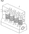
- Fig. 1 shows the structure of an entire engine 1 made of an aluminum alloy having cylinder liners 2 according to the present embodiment.
- the engine 1 includes a cylinder block 11 and a cylinder head 12.
- the cylinder block 11 includes a plurality of cylinders 13.
- Each cylinder 13 includes one cylinder liner 2.
- Each liner inner circumferential surface 21 defines a cylinder bore 15.
- an alloy specified in Japanese Industrial Standard (JIS) ADC10 (related United States standard, ASTM A380.0) or an alloy specified in JIS ADC12 (related United States standard, ASTM A383.0) may be used.
- JIS ADC10 Japanese Industrial Standard
- JIS ADC12 related United States standard, ASTM A383.0
- ASTM A380.0 Japanese Industrial Standard
- ASTM A383.0 an alloy specified in JIS ADC12
- ASTM A383.0 Japanese Industrial Standard
- an aluminum alloy of ADC 12 is used as the material for the cylinder block 11.
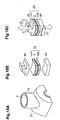
- Fig. 2 is a perspective view illustrating the cylinder liner 2 according to the present invention.
- the cylinder liner 2 is made of cast iron.
- the composition of the cast iron is set, for example, as shown in Fig. 3 .
- the components listed in table "Basic Component” may be selected as the composition of the cast iron.
- components listed in table “Auxiliary Component” may be added.
- the liner outer circumferential surface 22 of the cylinder liner 2 has projections 3, each having a constricted shape.
- the projections 3 are formed on the entire liner outer circumferential surface 22 from a liner upper end 23, which is an upper end of the cylinder liner 2, to a liner lower end 24, which is a lower end of the cylinder liner 2.
- the liner upper end 23 is an end of the cylinder liner 2 that is located at a combustion chamber in the engine 1.
- the liner lower end 24 is an end of the cylinder liner 2 that is located at a portion opposite to the combustion chamber in the engine 1.
- a film 5 is formed on the liner outer circumferential surface 22. More specifically, the film 5 is formed on the liner outer circumferential surface 22 in an area from the liner upper end 23 to a liner middle portion 25, which is a middle portion of the cylinder liner 2 in the axial direction of the cylinder 13. The film 5 is formed along the entire circumferential direction of the cylinder liner 2.
- the film 5 is formed of a sprayed layer of a ceramic material (ceramic sprayed layer 51).
- ceramic sprayed layer 51 alumina is used as the ceramic material forming the ceramic sprayed layer 51.
- the sprayed layer 51 is formed by spraying (plasma spraying or HVOF spraying).
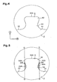
- Fig. 4 is a model diagram showing a projection 3.
- a direction of arrow A which is a radial direction of the cylinder liner 2
- a direction of arrow B which is the axial direction of the cylinder liner 2
- Fig. 4 shows the shape of the projection 3 as viewed in the radial direction of the projection 3.
- the projection 3 is integrally formed with the cylinder liner 2.
- the projection 3 is coupled to the liner outer circumferential surface 22 at a proximal end 31.
- a smooth and flat top surface 32A that corresponds to a distal end surface of the projection 3 is formed.
- a constriction 33 is formed between the proximal end 31 and the distal end 32.
- the constriction 33 is formed such that its cross-sectional area along the axial direction of the projection 3 (axial direction cross-sectional area SR) is less than an axial direction cross-sectional area SR at the proximal end 31 and at the distal end 32.
- the projection 3 is formed such that the axial direction cross-sectional area SR gradually increases from the constriction 33 to the proximal end 31 and to the distal end 32.
- Fig. 5 is a model diagram showing the projection 3, in which a constriction space 34 of the cylinder liner 2 is marked.
- the constriction 33 of each projection 3 creates the constriction space 34 (shaded areas in Fig. 5 ).
- the constriction space 34 is a space surrounded by an imaginary cylindrical surface circumscribing a largest distal portion 32B (in Fig. 5 , lines D-D corresponds to the cylindrical surface) and a constriction surface 33A, which is the surface of the constriction 33.
- the largest distal portion 32B represents a portion at which the diameter of the projection 3 is the longest in the distal end 32.
- the cylinder block 11 and the cylinder liners 2 are bonded to each other with part of the cylinder block 11 located in the constriction spaces 34, in other words, with the cylinder block 11 engaged with the projections 3. Therefore, sufficient liner bond strength, which is the bond strength of the cylinder block 11 and the cylinder liners 2, is ensured. Also, since the increased liner bond strength suppresses deformation of the cylinder bores 15, the friction is reduced. Accordingly, the fuel consumption rate is improved.
- the thickness of the film 5 is referred to as a film thickness TP.
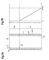
- Fig. 6A is a cross-sectional view of the cylinder liner 2 along the axial direction.
- Fig. 6B shows one example of variation in the temperature of the cylinder 13, specifically, in the cylinder wall temperature TW along the axial direction of the cylinder 13 in a normal operating state of the engine 1.
- the cylinder liner 2 from which the film 5 is removed will be referred to as a reference cylinder liner.
- An engine having the reference cylinder liners will be referred to as a reference engine.
- the position of the film 5 is determined based on the cylinder wall temperature TW in the reference engine.
- the solid line represents the cylinder wall temperature TW of the reference engine
- the broken line represents the cylinder wall temperature TW of the engine 1 of the present embodiment.
- the highest temperature of the cylinder wall temperature TW is referred to as a maximum cylinder wall temperature TWH
- the lowest temperature of the cylinder wall temperature TW will be referred to as a minimum cylinder wall temperature TWL.
- the cylinder wall temperature TW varies in the following manner.
- the cylinder wall temperature TW at a position corresponding to the low temperature liner portion 27 significantly falls below an appropriate temperature. This significantly increases the viscosity of the engine oil in the vicinity of the position. That is, the fuel consumption rate is inevitably degraded by the increase in the friction of the piston. Such deterioration of the fuel consumption rate due to the lowered cylinder wall temperature TW is particularly noticeable in engines in which the thermal conductivity of the cylinder block is relatively great (for example, an engine made of an aluminum alloy).
- the film 5 is formed on the low temperature liner portion 27, so that the thermal conductivity between the cylinder block 11 and the low temperature liner portion 27 is reduced. This increases the cylinder wall temperature TW at the low temperature liner portion 27.
- the cylinder block 11 and the low temperature liner portion 27 are bonded to each other with the film 5 having a heat insulation property in between. This reduces the thermal conductivity between the cylinder block 11 and the low temperature liner portion 27. Accordingly, the cylinder wall temperature TW in the low temperature liner portion 27 is increased. This causes the minimum cylinder wall temperature TWL to be a minimum cylinder wall temperature TWL2, which is higher than the minimum cylinder wall temperature TWL1. As the cylinder wall temperature TW increases, the viscosity of the engine oil is lowered, which reduces the friction of the piston. Accordingly, the fuel consumption rate is improved.
- a wall temperature boundary 28, which is the boundary between the high temperature liner portion 26 and the low temperature liner portion 27, can be obtained based on the cylinder wall temperature TW of the reference engine.
- the length of the low temperature liner portion 27 (the length from the liner lower end 24 to the wall temperature boundary 28) is two thirds to three quarter of the entire length of the cylinder liner 2 (the length from the liner upper end 23 to the liner lower end 24). Therefore, when determining the position of the film 5, two-thirds to three-quarters range from the liner lower end 24 in the entire liner length may be treated as the low temperature liner portion 27 without precisely determining the wall temperature boundary 28.
- FIG. 7A is a cross-sectional view of the cylinder liner 2 taken along the axial direction.
- Fig. 7B shows the relationship between the axial position and the film thickness TP in the cylinder liner 2.
- the film thickness TP is determined in the following manner.
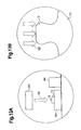
- Fig. 8 is an enlarged view showing encircled part ZC of Fig. 6A .
- the film 5 is formed on the liner outer circumferential surface 22 such that the constriction spaces 34 are not filled. That is, the film 5 is formed such that, when performing the insert casting of the cylinder liners 2, the casting material fills the constriction spaces 34. If the constriction spaces 34 are filled by the film 5, the casting material will not fill the constriction spaces 34. Thus, no anchor effect of the projections 3 will be obtained in the low temperature liner portion 27.
- FIGs. 9 and 10 are cross-sectional views showing the cylinder block 11 taken along the axis of the cylinder 13.
- Fig. 9 is a cross-sectional view of encircled part ZA of Fig. 1 and shows the bonding state between the cylinder block 11 and the low temperature liner portion 27.
- the cylinder block 11 is bonded to the low temperature liner portion 27 in a state where the cylinder block 11 is engaged with the projections 3.
- the cylinder block 11 and the low temperature liner portion 27 are bonded to each other with the film 5 in between.
- the film 5 is formed of alumina, which has a lower thermal conductivity than that of the cylinder block 11, the cylinder block 11 and the film 5 are mechanically bonded to each other in a state of a low thermal conductivity.
- Fig. 10 is a cross-sectional view of encircled part ZB of Fig. 1 and shows the bonding state between the cylinder block 11 and the high temperature liner portion 26.
- the cylinder block 11 is bonded to the high temperature liner portion 26 in a state where the cylinder block 11 is engaged with the projections 3. Therefore, sufficient bond strength between the cylinder block 11 and the high temperature liner portion 26 is ensured by the anchor effect of the projections 3. Also, sufficient thermal conductivity between the cylinder block 11 and the high temperature liner portion 26 is ensured.
- a first area ratio SA As parameters related to the projection 3, a first area ratio SA, a second area ratio SB, a standard cross-sectional area SD, a standard projection density NP, and a standard projection height HP are defined.
- a measurement height H, a first reference plane PA, and a second reference plane PB, which are basic values for the above parameters related to the projection 3, will now be described.
- the parameters [A] to [E] are set to be within the selected ranges in Table 1, so that the effect of increase of the liner bond strength by the projections 3 and the filling factor of the casting material between the projections 3 are increased.
- the projections 3 are formed on the cylinder liner 2 to be independent from one another on the first reference plane PA in the present embodiment. In other words, a cross-section of each projection 3 by a plane containing the contour line representing a height of 0.4 mm from its proximal end is independent from cross-sections of the other projections 3 by the same plane. This further increases the filling factor.
- the cylinder liner 2 is produced by centrifugal casting.
- the following parameters [A] to [F] related to the centrifugal casting are set be within selected range of Table 2.
- the production of the cylinder liner 2 is executed according to the procedure shown in Figs. 11A to 11F .
- a method for measuring the parameters related to projections 3 using a three-dimensional laser will be described.
- the standard projection height HP is measured by another method.
- Each of the parameters related to the projections 3 can be measured in the following manner.
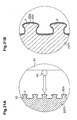
- Fig. 14 is a part of one example of the contour diagram 85.
- Fig. 15 shows the relationship between the measurement height H and contour lines HL.
- the contour diagram 85 of Fig. 14 is drawn based in accordance with the liner outer circumferential surface 22 having a projection 3 that is different from the projection 3 of Fig. 15 .
- the contour lines HL are shown at every predetermined value of the measurement height H.
- contour lines HL are shown at a 0.2 mm interval from the measurement height of 0 mm to the measurement height of 1.0 mm in the contour diagram 85.
- contour lines HL0 of the measurement height of 0 mm contour lines HL2 of the measurement height of 0.2 mm, contour lines HL4 of the measurement height of 0.4 mm, contour lines HL6 of the measurement height of 0.6 mm, contour lines HL8 of the measurement height of 0.8 mm, and contour lines HL10 of the measurement height of 1.0 mm are shown.
- the contour lines HL 4 are contained in first reference plane PA.
- the contour lines HL 2 are contained in the second reference plane PB.
- Fig. 14 shows a diagram in which the contour lines HL are shown at a 0.2 mm interval, the distance between the contour lines HL may be changed as necessary.
- Fig. 16 is a part of a first contour diagram 85A, in which the contour lines HL4 of the measurement height of 0.4 mm in the contour diagram 85 are shown in solid lines and the other contour lines HL in the contour diagram 85 are shown in dotted lines.
- Fig. 17 is a part of a second contour diagram 85B, in which the contour lines HL2 of the measurement height of 0.2 mm in the contour diagram 85 are shown in solid lines and the other contour lines HL in the contour diagram 85 are shown in dotted lines.
- regions each surrounded by the contour line HL4 in the contour diagram 85 are defined as the first regions RA. That is, the shaded areas in the first contour diagram 85A correspond to the first regions RA. Regions each surrounded by the contour line HL2 in the contour diagram 85 are defined as the second regions RB. That is, the shaded areas in the second contour diagram 85B correspond to the second regions RB.
- the parameters related to the projections 3 are computed in the following manner based on the contour diagram 85.
- the symbol ST represents the area of the entire contour diagram 85.
- the symbol SRA represents the total area of the first regions RA in the contour diagram 85.
- Fig. 16 which shows a part of the first contour diagram 85A
- the area of the rectangular zone surrounded by the frame corresponds to the area ST
- the area of the shaded zone corresponds to the area SRA.
- the contour diagram 85 is assumed to include only the liner outer circumferential surface 22.
- the symbol ST represents the area of the entire contour diagram 85.
- the symbol SRB represents the total area of the second regions RB in the entire contour diagram 85.
- Fig. 17 which shows a part of the second contour diagram 85B
- the area of the rectangular zone surrounded by the frame corresponds to the area ST
- the area of the shaded zone corresponds to the area SRB.
- the contour diagram 85 is assumed to include only the liner outer circumferential surface 22.
- the standard cross-sectional area SD can be computed as the area of each first region RA in the contour diagram 85.
- Fig. 16 which shows a part of the first contour diagram 85A, is used as a model
- the area of the shaded area corresponds to standard cross-sectional area SD.
- the standard projection density NP can be computed as the number of projections 3 per unit area in the contour diagram 85 (in this embodiment, 1 cm 2 ).
- the standard projection height HP represents the height of each projection 3.
- the height of each projection 3 may be a mean value of the heights of the projection 3 at several locations.
- the height of each projection 3 can be measured by a measuring device such as a dial depth gauge.
- Whether the projections 3 are independently provided on the first reference plane PA can be checked based on the first regions RA in the contour diagram 85. That is, when each first region RA does not interfere with other first regions RA, it is confirmed that the projections 3 are independently provided on the first reference plane PA. In other words, it is confirmed that a cross-section of each projection 3 by a plane containing the contour line representing a height of 0.4 mm from its proximal end is independent from cross-sections of the other projections 3 by the same plane.
- the evaluation of the bond strength of the low temperature liner portion 27 may be performed according to the procedure of the following steps [1] to [5].
- the bond strength between the cylinder block 11 and the cylinder liner 2 of the engine 1 according to the present embodiment was measured according to the above evaluation method. It was confirmed that the bond strength of the engine 1 was sufficiently higher than that of the reference engine.
- the cylinder liner 2 according to the present embodiment provides the following advantages.
- the film 5 is formed such that the film thickness TP is gradually increased from the wall temperature boundary 28 to the liner lower end 24.
- the film thickness TP may be constant in the low temperature liner portion 27.
- the setting of the film thickness TP may be changed as necessary in a range that does not cause the cylinder wall temperature TW to be greatly different from the appropriate temperature in the entire low temperature liner portion 27.
- the second embodiment is configured by changing the formation of the film 5 in the cylinder liner 2 according to the first embodiment in the following manner.
- the cylinder liner 2 according to the second embodiment is the same as that of the first embodiment except for the configuration described below.
- Fig. 19 is an enlarged view showing encircled part ZC of Fig. 6A .
- a film 5 is formed on a liner outer circumferential surface 22 of a low temperature liner portion 27.
- the film 5 is formed of a sprayed layer of an iron based material (iron sprayed layer 52).
- the iron sprayed layer 52 is formed by laminating a plurality of thin sprayed layers 52A.
- the iron sprayed layer 52 (the thin sprayed layers 52A) contains a number of layers of oxides and pores.
- Fig. 20 is a cross-sectional view of encircled part ZA of Fig. 1 and shows the bonding state between the cylinder block 11 and the low temperature liner portion 27.
- the cylinder block 11 is bonded to the low temperature liner portion 27 in a state where the cylinder block 11 is engaged with the projections 3.
- the cylinder block 11 and the low temperature liner portion 27 are bonded to each other with the film 5 in between.
- the film 5 is formed of a sprayed layer containing a number of layers of oxides and pores, the cylinder block 11 and the film 5 are mechanically bonded to each other in a state of low thermal conductivity.
- the film 5 is formed by arc spraying.
- the film 5 may be formed through the following procedure.
- the wire 92 is melt and changed into particles, the surfaces of which are oxidized.
- the iron sprayed layer 52 contains a number of layers of oxides. This further increases the heat insulation property of the film 5.
- the diameter of the wire 92 used in the arc spraying is set equal to or greater than 0.8 mm. Therefore, powder of the wire 92 having relatively large particle sizes are sprayed onto the low temperature liner portion 27, and the formed iron sprayed layer 52 includes a number of pores. That is, the film 5 having a high heat insulation property is formed.
- the diameter of the wire 92 is less than 0.8 mm, powder of the wire 92 having small particle sizes are sprayed onto the low temperature liner portion 27. Thus, compared to the case where the diameter of the wire 92 is equal to or greater than 0.8 mm, the number of pores in the iron sprayed layer 52 is significantly reduced.
- the cylinder liner 2 of the second embodiment provides the following advantage.
- the diameter of the wire 92 is set to 0.8 mm when forming the film 5.
- the selected range of the diameter of the wire 92 may be set in the following manner. That is, the selected range of the diameter of the wire 92 may be set to a range from 0.8 mm to 2.4 mm. If the diameter of the wire 92 is set greater than 2.4 mm, the particles of the wire 92 will be large. It is therefore predicted that the strength of the iron sprayed layer 52 will be significantly reduced.
- the third embodiment is configured by changing the formation of the film 5 in the cylinder liner 2 according to the first embodiment in the following manner.
- the cylinder liner 2 according to the third embodiment is the same as that of the first embodiment except for the configuration described below.
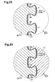
- Fig. 22 is an enlarged view showing encircled part ZC of Fig. 6A .
- a film 5 is formed on a liner outer circumferential surface 22 of a low temperature liner portion 27 in the cylinder liner 2.
- the film 5 is formed of a first sprayed layer 53A formed on the surface of he cylinder liner 2 and a second sprayed layer 53B formed on the surface of the first sprayed layer 53A.
- the first sprayed layer 53A is formed of a ceramic material (alumina or zirconia).
- a material that reduces the thermal conductivity between the cylinder block 11 and the low temperature liner portion 27 may be used.
- the second sprayed layer 53B is formed of an aluminum alloy (Al-Si alloy or Al-Cu alloy).
- Al-Si alloy or Al-Cu alloy As the material for the second sprayed layer 53B, a material having a high bonding property with the cylinder block 11 may be used.
- Fig. 23 is a cross-sectional view of encircled part ZA of Fig. 1 and shows the bonding state between the cylinder block 11 and the low temperature liner portion 27.
- the cylinder block 11 is bonded to the low temperature liner portion 27 in a state where the cylinder block 11 is engaged with the projections 3.
- the cylinder block 11 and the low temperature liner portion 27 are bonded to each other with the film 5 in between.
- the film 5 is formed of a ceramic material, which has a lower thermal conductivity than that of the cylinder block 11, the cylinder block 11 and the film 5 are mechanically bonded to each other in a state of a low thermal conductivity.
- the film 5 includes the second sprayed layer 53B having a high boding property with the cylinder block 11, the bond strength between the film 5 and the cylinder block 11 is increased compared to a case where the film 5 is formed only of the first sprayed layer 53A.
- the film 5 is formed by plasma spraying.
- the film 5 may be formed through the following procedure.
- the cylinder liner 2 of the third embodiment provides the following advantage.
- the fourth embodiment is configured by changing the formation of the film 5 in the cylinder liner 2 according to the first embodiment in the following manner.
- the cylinder liner 2 according to the fourth embodiment is the same as that of the first embodiment except for the configuration described below.
- Fig. 24 is an enlarged view showing encircled part ZC of Fig. 6A .
- a film 5 is formed on a liner outer circumferential surface 22 of a low temperature liner portion 27 in the cylinder liner 2.
- the film 5 is formed of an oxide layer 54.
- Fig. 25 is a cross-sectional view of encircled part ZA of Fig. 1 and shows the bonding state between the cylinder block 11 and the low temperature liner portion 27.
- the cylinder block 11 is bonded to the low temperature liner portion 27 in a state where the cylinder block 11 is engaged with the projections 3.
- the cylinder block 11 and the low temperature liner portion 27 are bonded to each other with the film 5 in between.
- the film 5 is formed of oxides, the cylinder block 11 and the film 5 are mechanically bonded to each other in a state of low thermal conductivity.
- the film 5 is formed by high-frequency heating.
- the film 5 may be formed through the following procedure.
- heating of the low temperature liner portion 27 melts the distal end 32 of each projection 3.
- an oxide layer 54 is thicker at the distal end 32 than in other portions. Accordingly, the heat insulation property about the distal end 32 of the projection 3 is improved.
- the film 5 is formed to have a sufficient thickness at the constriction 33 of each projection 3. Therefore, the heat insulation property about the constriction 33 is further improved.
- the cylinder liner 2 of the third embodiment provides the following advantage.
- the fifth embodiment is configured by changing the formation of the film 5 in the cylinder liner 2 according to the first embodiment in the following manner.
- the cylinder liner 2 according to the fifth embodiment is the same as that of the first embodiment except for the configuration described below.
- Fig. 26 is an enlarged view showing encircled part ZC of Fig. 6A .
- a film 5 is formed on a liner outer circumferential surface 22 of a low temperature liner portion 27 in the cylinder liner 2.
- the film 5 is formed of a mold release agent layer 55, which is a layer of mold release agent for die casting.
- the following mold release agents may be used.
- Fig. 27 is a cross-sectional view of encircled part ZA of Fig. 1 and shows the bonding state between the cylinder block 11 and the low temperature liner portion 27.
- the cylinder block 11 is bonded to the low temperature liner portion 27 in a state where the cylinder block 11 is engaged with the projections 3.
- the cylinder block 11 and the low temperature liner portion 27 are bonded to each other with the film 5 in between.
- the film 5 is formed of a mold release agent, which has a low adhesion with the cylinder block 11, the cylinder block 11 and the film 5 are bonded to each other with gaps 5H.
- the casting material is solidified in a state where sufficient adhesion between the casting material and the mold release agent layer 55 is not established at several portions. Accordingly, the gaps 5H are created between the cylinder block 11 and the mold release agent layer 55.
- the cylinder liner 2 of the fifth embodiment provides the following advantage.
- the sixth embodiment is configured by changing the formation of the film 5 in the cylinder liner 2 according to the first embodiment in the following manner.
- the cylinder liner 2 according to the sixth embodiment is the same as that of the first embodiment except for the configuration described below.
- Fig. 26 is an enlarged view showing encircled part ZC of Fig. 6A .
- a film 5 is formed on a liner outer circumferential surface 22 of a low temperature liner portion 27.
- the film 5 is formed of a mold wash layer 56, which is a layer of mold wash for the centrifugal casting mold.
- the following mold washes may be used.
- Fig. 27 is a cross-sectional view of encircled part ZA of Fig. 1 and shows the bonding state between the cylinder block 11 and the low temperature liner portion 27.
- the cylinder block 11 is bonded to the low temperature liner portion 27 in a state where the cylinder block 11 is engaged with the projections 3.
- the cylinder block 11 and the low temperature liner portion 27 are bonded to each other with the film 5 in between.
- the film 5 is formed of a mold wash, which has a low adhesion with the cylinder block 11, the cylinder block 11 and the film 5 are bonded to each other with gaps 5H.
- the casting material is solidified in a state where sufficient adhesion between the casting material and the mold wash layer 56 is not established at several portions. Accordingly, the gaps 5H are created between the cylinder block 11 and the mold wash layer 56.
- the cylinder liner 2 of the sixth embodiment provides the following advantage.
- the seventh embodiment is configured by changing the formation of the film 5 in the cylinder liner 2 according to the first embodiment in the following manner.
- the cylinder liner 2 according to the seventh embodiment is the same as that of the first embodiment except for the configuration described below.
- Fig. 26 is an enlarged view showing encircled part ZC of Fig. 6A .
- a film 5 is formed on a liner outer circumferential surface 22 of a low temperature liner portion 27 in the cylinder liner 2.
- the film 5 is formed of a low adhesion agent layer 57.
- the low adhesion agent refers to a liquid material prepared using a material having a low adhesion with the cylinder block 11.
- the following low adhesion agents may be used.
- Fig. 27 is a cross-sectional view of encircled part ZA of Fig. 1 and shows the bonding state between the cylinder block 11 and the low temperature liner portion 27.
- the cylinder block 11 is bonded to the low temperature liner portion 27 in a state where the cylinder block 11 is engaged with the projections 3.
- the cylinder block 11 and the low temperature liner portion 27 are bonded to each other with the film 5 in between.
- the film 5 is formed of a low adhesion agent, which has a low adhesion with the cylinder block 11, the cylinder block 11 and the film 5 are bonded to each other with gaps 5H.
- the casting material is solidified in a state where sufficient adhesion between the casting material and the low adhesion agent layer 57 is not established at several portions. Accordingly, the gaps 5H are created between the cylinder block 11 and the low adhesion agent layer 57.
- the film 5 is formed by coating and drying the low adhesion agent.
- the film 5 may be formed through the following procedure.
- the cylinder liner 2 according to the seventh embodiment provides advantages similar to the advantages (1) to (11) in the first embodiment.
- the above illustrated seventh embodiment may be modified as shown below.
- the following agents may be used.
- the eighth embodiment is configured by changing the formation of the film 5 in the cylinder liner 2 according to the first embodiment in the following manner.
- the cylinder liner 2 according to the eighth embodiment is the same as that of the first embodiment except for the configuration described below.
- Fig. 26 is an enlarged view showing encircled part ZC of Fig. 6A .
- a film 5 is formed on a liner outer circumferential surface 22 of a low temperature liner portion 27 in the cylinder liner 2.
- the film 5 is formed of a metallic paint layer 58.
- Fig. 27 is a cross-sectional view of encircled part ZA of Fig. 1 and shows the bonding state between the cylinder block 11 and the low temperature liner portion 27.
- the cylinder block 11 is bonded to the low temperature liner portion 27 in a state where the cylinder block 11 is engaged with the projections 3.
- the cylinder block 11 and the low temperature liner portion 27 are bonded to each other with the film 5 in between.
- the film 5 is formed of a metallic paint, which has a low adhesion with the cylinder block 11, the cylinder block 11 and the film 5 are bonded to each other with gaps 5H.
- the casting material is solidified in a state where sufficient adhesion between the casting material and the metallic paint layer 58 is not established at several portions. Accordingly, the gaps 5H are created between the cylinder block 11 and the metallic paint layer 58.
- the cylinder liner 2 according to the eighth embodiment provides advantages similar to the advantages (1) to (11) in the first embodiment.
- the ninth embodiment is configured by changing the formation of the film 5 in the cylinder liner 2 according to the first embodiment in the following manner.
- the cylinder liner 2 according to the ninth embodiment is the same as that of the first embodiment except for the configuration described below.
- Fig. 26 is an enlarged view showing encircled part ZC of Fig. 6A .
- a film 5 is formed on a liner outer circumferential surface 22 of a low temperature liner portion 27 in the cylinder liner 2.
- the film 5 is formed of a high-temperature resin layer 59.
- Fig. 27 is a cross-sectional view of encircled part ZA of Fig. 1 and shows the bonding state between the cylinder block 11 and the low temperature liner portion 27.
- the cylinder block 11 is bonded to the low temperature liner portion 27 in a state where the cylinder block 11 is engaged with the projections 3.
- the cylinder block 11 and the low temperature liner portion 27 are bonded to each other with the film 5 in between.
- the film 5 is formed of a high-temperature resin, which has a low adhesion with the cylinder block 11, the cylinder block 11 and the film 5 are bonded to each other with gaps 5H.
- the casting material is solidified in a state where sufficient adhesion between the casting material and the high-temperature resin layer 59 is not established at several portions. Accordingly, the gaps 5H are created between the cylinder block 11 and the high-temperature resin layer 59.
- the cylinder liner 2 according to the ninth embodiment provides advantages similar to the advantages (1) to (11) in the first embodiment.
- the tenth embodiment is configured by changing the formation of the film 5 in the cylinder liner 2 according to the first embodiment in the following manner.
- the cylinder liner 2 according to the tenth embodiment is the same as that of the first embodiment except for the configuration described below.
- Fig. 26 is an enlarged view showing encircled part ZC of Fig. 6A .
- a film 5 is formed on a liner outer circumferential surface 22 of a low temperature liner portion 27 in the cylinder liner 2.
- the film 5 is formed of a chemical conversion treatment layer 50, which is a layer formed through chemical conversion treatment.
- the following layers maybe formed.
- Fig. 27 is a cross-sectional view of encircled part ZA of Fig. 1 and shows the bonding state between the cylinder block 11 and the low temperature liner portion 27.
- the cylinder block 11 is bonded to the low temperature liner portion 27 in a state where the cylinder block 11 is engaged with the projections 3.
- the cylinder block 11 and the low temperature liner portion 27 are bonded to each other with the film 5 in between.
- the film 5 is formed of a chemical conversion treatment layer, which has a low adhesion with the cylinder block 11, the cylinder block 11 and the film 5 are bonded to each other with gaps 5H.
- the casting material is solidified in a state where sufficient adhesion between the casting material and the chemical conversion treatment layer 50 is not established at several portions. Accordingly, the gaps 5H are created between the cylinder block 11 and the chemical conversion treatment layer 50.
- the film 5 since the film 5 is formed by a chemical conversion treatment, the film 5 has a sufficient thickness at the constriction 33 of the projection 3. This allows the gaps 5H to be easily created about the constriction 33 of the cylinder block 11. Therefore, the heat insulation property about the constriction 33 is improved.
- the cylinder liner 2 of the tenth embodiment provides the following advantage.
- the selected ranges of the first area ratio SA and the second area ratio SB are set be in the selected ranges shown in Table 1. However, the selected ranges may be changed as shown below.
- the first area ratio SA 10% to 30%
- the second area ratio SB 20% to 45%
- This setting increases the liner bond strength and the filling factor of the casting material to the spaces between the projections 3.
- the selected range of the standard projection height HP is set to a range from 0.5 mm to 1.0 mm.
- the selected range may be changed as shown below. That is, the selected range of the standard projection height HP may be set to a range from 0.5 mm to 1.5 mm.
- the film 5 is not formed on the liner outer circumferential surface 22 of the high temperature liner portion 26, while the film 5 is formed on the liner outer circumferential surface 22 of the low temperature liner portion 27.
- This configuration may be modified as follows. That is, the film 5 may be formed on the liner outer circumferential surface 22 of both of the low temperature liner portion 27 and the high temperature liner portion 26. This configuration reliably prevents the cylinder wall temperature TW at some locations from being excessively lowered.
- the film 5 is formed along the entire circumference of the cylinder liner 2.
- the position of the film 5 may be changed as shown below. That is, with respect to the direction along which the cylinders 13 are arranged, the film 5 may be omitted from sections of the liner outer circumferential surfaces 22 that face the adjacent cylinder bores 15.
- the films 5 may be formed in sections except for sections of the liner outer circumferential surfaces 2 that face the liner outer circumferential surfaces 2 of the adjacent cylinder liners 2 with respect to the arrangement direction of the cylinders 13.
- the method for forming the film 5 is not limited to the methods shown in the above embodiments (spraying, coating, resin coating, and chemical conversion treatment). Any other method may be applied as necessary.
- the configuration of the formation of the film 5 according to the above embodiments may be modified as shown below. That is, the film 5 may be formed of any material as long as at least one of the following conditions (A) and (B) is met.
- the film 5 is formed on the cylinder liner 2 with the projections 3 the related parameters of which are in the selected ranges of Table 1.
- the film 5 may be formed on any cylinder liner as long as the projections 3 are formed on it.
- the film 5 is formed on the cylinder liner 2 on which the projections 3 are formed.
- the film 5 may be formed on a cylinder liner on which projections without constrictions are formed.
- the film 5 is formed on the cylinder liner 2 on which the projections 3 are formed.
- the film 5 may be formed on a cylinder liner on which no projections are formed.
- the cylinder liner of the present embodiment is applied to an engine made of an aluminum alloy.
- the cylinder liner of the present invention may be applied to an engine made of, for example, a magnesium alloy.
- the cylinder liner of the present invention may be applied to any engine that has a cylinder liner. Even in such case, the advantages similar to those of the above embodiments are obtained if the invention is embodied in a manner similar to the above embodiments.
Landscapes
- Engineering & Computer Science (AREA)
- Chemical & Material Sciences (AREA)
- Mechanical Engineering (AREA)
- Combustion & Propulsion (AREA)
- General Engineering & Computer Science (AREA)
- Materials Engineering (AREA)
- Chemical Kinetics & Catalysis (AREA)
- Metallurgy (AREA)
- Organic Chemistry (AREA)
- Physics & Mathematics (AREA)
- Plasma & Fusion (AREA)
- Cylinder Crankcases Of Internal Combustion Engines (AREA)
- Pistons, Piston Rings, And Cylinders (AREA)
Applications Claiming Priority (2)
| Application Number | Priority Date | Filing Date | Title |
|---|---|---|---|
| JP2005200999A JP4584058B2 (ja) | 2005-07-08 | 2005-07-08 | シリンダライナ及びその製造方法 |
| EP06781043.2A EP1902209B1 (de) | 2005-07-08 | 2006-07-06 | Zylinderlaufbuchse und verfahren zu deren herstellung |
Related Parent Applications (3)
| Application Number | Title | Priority Date | Filing Date |
|---|---|---|---|
| EP06781043.2A Division EP1902209B1 (de) | 2005-07-08 | 2006-07-06 | Zylinderlaufbuchse und verfahren zu deren herstellung |
| EP06781043.2A Division-Into EP1902209B1 (de) | 2005-07-08 | 2006-07-06 | Zylinderlaufbuchse und verfahren zu deren herstellung |
| EP06781043.2 Division | 2006-07-06 |
Publications (3)
| Publication Number | Publication Date |
|---|---|
| EP2151568A2 true EP2151568A2 (de) | 2010-02-10 |
| EP2151568A3 EP2151568A3 (de) | 2010-09-01 |
| EP2151568B1 EP2151568B1 (de) | 2012-05-16 |
Family
ID=37102027
Family Applications (2)
| Application Number | Title | Priority Date | Filing Date |
|---|---|---|---|
| EP09012291A Active EP2151568B1 (de) | 2005-07-08 | 2006-07-06 | Zylinderblock mit einer Zylinderlaufbüchse und Herstellungsverfahren dafür |
| EP06781043.2A Active EP1902209B1 (de) | 2005-07-08 | 2006-07-06 | Zylinderlaufbuchse und verfahren zu deren herstellung |
Family Applications After (1)
| Application Number | Title | Priority Date | Filing Date |
|---|---|---|---|
| EP06781043.2A Active EP1902209B1 (de) | 2005-07-08 | 2006-07-06 | Zylinderlaufbuchse und verfahren zu deren herstellung |
Country Status (11)
| Country | Link |
|---|---|
| US (1) | US7753023B2 (de) |
| EP (2) | EP2151568B1 (de) |
| JP (1) | JP4584058B2 (de) |
| KR (1) | KR100984990B1 (de) |
| CN (3) | CN101258318B (de) |
| AU (1) | AU2006267413B2 (de) |
| BR (1) | BRPI0612786B1 (de) |
| CA (2) | CA2614551C (de) |
| ES (2) | ES2383643T3 (de) |
| RU (1) | RU2388576C2 (de) |
| WO (1) | WO2007007822A1 (de) |
Cited By (2)
| Publication number | Priority date | Publication date | Assignee | Title |
|---|---|---|---|---|
| WO2013036747A1 (en) * | 2011-09-07 | 2013-03-14 | Federal-Mogul Corporation | Cylinder liner with a thermal barrier coating |
| DE102012211866A1 (de) * | 2012-07-06 | 2014-01-09 | Mahle International Gmbh | Zylinderlaufbuchse |
Families Citing this family (23)
| Publication number | Priority date | Publication date | Assignee | Title |
|---|---|---|---|---|
| JP4491385B2 (ja) * | 2005-07-08 | 2010-06-30 | トヨタ自動車株式会社 | 鋳ぐるみ用部品、シリンダブロック及びシリンダライナ製造方法 |
| EP2238325A2 (de) * | 2007-12-21 | 2010-10-13 | Green Partners Technology Holdings Gmbh | Eine vorrichtung zur zuführung von verdampfbarer flüssigkeit einsetzende gasturbinensysteme und verfahren |
| US8783279B2 (en) * | 2009-07-24 | 2014-07-22 | Mogas Industries, Inc. | Tubular member with thermal sleeve liner |
| KR101164459B1 (ko) * | 2009-09-02 | 2012-07-18 | 신닛떼쯔 엔지니어링 가부시끼가이샤 | 다층 내화물 구조의 노의 해체 방법 |
| JP5572847B2 (ja) * | 2010-03-17 | 2014-08-20 | 株式会社Moresco | シリンダライナ及びその製造方法 |
| JP2012067740A (ja) * | 2010-08-25 | 2012-04-05 | Tpr Co Ltd | 鋳包用シリンダライナ |
| JP5579106B2 (ja) * | 2011-03-03 | 2014-08-27 | Tpr株式会社 | 支持部材 |
| RU2470266C2 (ru) * | 2011-03-21 | 2012-12-20 | Государственное образовательное учреждение высшего профессионального образования "Сибирская государственная геодезическая академия" (ГОУВПО "СГГА") | Способ градуировки резервуара шарового (сферического) для определения вместимости, соответствующей высоте его наполнения |
| WO2015009777A1 (en) | 2013-07-16 | 2015-01-22 | Federal-Mogul Corporation | Cylinder liner with bonding layer |
| US10094325B2 (en) * | 2014-01-28 | 2018-10-09 | ZYNP International Corp. | Cylinder liner |
| US9945318B2 (en) * | 2015-12-04 | 2018-04-17 | Hyundai Motor Company | Cylinder block |
| KR20170127903A (ko) * | 2016-05-13 | 2017-11-22 | 현대자동차주식회사 | 인서트 주조용 실린더 라이너 및 그 제조 방법 |
| JP6572851B2 (ja) | 2016-08-29 | 2019-09-11 | トヨタ自動車株式会社 | 内燃機関のシリンダブロックおよびその製造方法 |
| CN107639223B (zh) * | 2017-07-25 | 2019-08-20 | 中原内配集团安徽有限责任公司 | 一种铸铁缸套的制备工艺 |
| US10400707B2 (en) * | 2017-07-26 | 2019-09-03 | GM Global Technology Operations LLC | Method and system for processing an automotive engine block |
| JP6979171B2 (ja) * | 2017-11-16 | 2021-12-08 | スズキ株式会社 | 鋳包み用部材及びその製造方法 |
| CN108543923A (zh) * | 2018-05-04 | 2018-09-18 | 广东鸿图南通压铸有限公司 | 一种主轴承盖镶件下缸体的压铸方法 |
| CN110894813B (zh) * | 2018-08-22 | 2023-05-02 | 帝伯爱尔株式会社 | 气缸套及其制造方法和使用气缸套的气缸体的制造方法 |
| CN110318902A (zh) * | 2019-04-23 | 2019-10-11 | 天津大学 | 疏水型气缸套外表面结构及疏水型气缸套 |
| US10907569B2 (en) * | 2019-06-19 | 2021-02-02 | Ford Global Technologies, Llc | Systems and methods for a cylinder bore coating fill material |
| CN112943470A (zh) * | 2019-11-26 | 2021-06-11 | 北京福田康明斯发动机有限公司 | 一种内燃机气缸套及内燃机 |
| DE102020122168A1 (de) * | 2020-08-25 | 2022-03-03 | Federal-Mogul Burscheid Gmbh | Zylinderlaufbuchse oder zylinder für einen verbrennungsmotor |
| DE202020106390U1 (de) | 2020-11-06 | 2022-02-08 | AMSBECK-Maschinentechnik GmbH | Kupplungsvorrichtung |
Citations (11)
| Publication number | Priority date | Publication date | Assignee | Title |
|---|---|---|---|---|
| FR1157842A (fr) | 1955-09-13 | 1958-06-04 | Air Reduction | Procédé et appareil de pulvérisation de métal |
| JPS53163405U (de) | 1977-05-30 | 1978-12-21 | ||
| US5537969A (en) | 1994-04-20 | 1996-07-23 | Honda Giken Kogyo Kabushiki Kaisha | Cylinder block |
| DE19937934A1 (de) | 1999-08-11 | 2001-02-15 | Bayerische Motoren Werke Ag | Zylinderkurbelgehäuse, Verfahren zur Herstellung der Zylinderlaufbuchsen dafür und Verfahren zur Herstellung des Zylinderkurbelgehäuses mit diesen Zylinderlaufbuchsen |
| DE10002440A1 (de) | 2000-01-21 | 2001-08-02 | Daimler Chrysler Ag | Zylinderlaufbuchse zum Eingießen in einen als Leichtmetall-Gußteil ausgebildeten Motorblock, Verbundgußteil daraus und Verfahren zu seiner Herstellung |
| WO2001058621A1 (en) | 2000-02-10 | 2001-08-16 | C.R.F. Societa Consortile Per Azioni | A method for producing a cylinder block for an internal combustion engine |
| US6286583B1 (en) | 1996-08-27 | 2001-09-11 | Daimlerchrysler Ag | Two part light metal coating and method of making same |
| EP1277539A1 (de) | 2001-07-12 | 2003-01-22 | Daido Tokushuko Kabushiki Kaisha | Draht auf Titan-Basis zur Bildung geschmolzener Metalle |
| RU2236608C2 (ru) | 2000-02-29 | 2004-09-20 | Абачараев Муса Магомедович | Состав теплозащитного покрытия цилиндровой втулки |
| EP1504833A1 (de) | 2002-05-13 | 2005-02-09 | Honda Giken Kogyo Kabushiki Kaisha | Gusseisernes inneres kühlglied und herstellungsverfahren dafür |
| DE10347510B3 (de) | 2003-10-13 | 2005-04-28 | Federal Mogul Burscheid Gmbh | Zylinderlaufbuchse mit einer zwei Schichten umfassenden Außenbeschichtung und Verfahren zu deren Ein- oder Umgießen zu einem Verbundkörper |
Family Cites Families (29)
| Publication number | Priority date | Publication date | Assignee | Title |
|---|---|---|---|---|
| US1955292A (en) * | 1933-05-27 | 1934-04-17 | Heintz & Kaufman Ltd | Method of making engine cylinders |
| US2085976A (en) * | 1936-02-25 | 1937-07-06 | Heintz & Kaufman Ltd | Cylinder liner |
| US3903951A (en) * | 1972-01-14 | 1975-09-09 | Toyota Motor Co Ltd | Method of manufacturing aluminum alloy cylinders and cylinder liners for internal combustion engines |
| JPS53135839A (en) | 1977-05-02 | 1978-11-27 | Kawasaki Heavy Ind Ltd | Line explosive spraying method for aluminum alloy cylinder |
| JPS55104400A (en) * | 1979-02-06 | 1980-08-09 | Kureha Chemical Ind Co Ltd | Detergent composition |
| JPS6058824B2 (ja) | 1979-09-25 | 1985-12-21 | 平沼産業株式会社 | 多検体塗布装置 |
| US4486938A (en) * | 1981-03-20 | 1984-12-11 | Hext Billy R | Process of remanufacturing pump cylinder liners |
| JPS6058824U (ja) * | 1983-09-30 | 1985-04-24 | いすゞ自動車株式会社 | エンジンの燃焼室壁部の断熱構造 |
| JPS61127348A (ja) * | 1984-11-27 | 1986-06-14 | 日本特殊陶業株式会社 | セラミツクスと金属との複合体 |
| JPS6252255A (ja) | 1985-08-29 | 1987-03-06 | Kubota Ltd | 圧力コントロ−ル機構 |
| JP2514097B2 (ja) * | 1990-03-15 | 1996-07-10 | 帝国ピストンリング株式会社 | シリンダライナ |
| IT1240746B (it) * | 1990-04-06 | 1993-12-17 | Temav Spa | Procedimento per ottenere un legame metallurgico continuo fra canne dei cilindri id il getto costituente il basamento di un motore a combustione interna |
| DE4013148C1 (de) * | 1990-04-25 | 1991-10-31 | Mercedes-Benz Aktiengesellschaft, 7000 Stuttgart, De | |
| JPH06508861A (ja) * | 1991-02-22 | 1994-10-06 | マサチューセッツ インスティチュート オブ テクノロジー | 潤滑油組成物及びこれによる内燃機関における摩擦損失の抑制方法 |
| US5671532A (en) * | 1994-12-09 | 1997-09-30 | Ford Global Technologies, Inc. | Method of making an engine block using coated cylinder bore liners |
| AT1621U1 (de) * | 1996-10-16 | 1997-08-25 | Avl Verbrennungskraft Messtech | Brennkraftmaschine mit innerer verbrennung |
| AT2906U1 (de) * | 1998-06-18 | 1999-06-25 | Avl List Gmbh | Zylinderbüchse für eine flüssigkeitsgekühlte brennkraftmaschine |
| US6138630A (en) * | 1999-10-28 | 2000-10-31 | Metalicos De Tecnologia Avanzada, S.A. De C.V. | Cylinder liners for aluminum motor blocks and methods of production |
| JP2001200751A (ja) | 2000-01-18 | 2001-07-27 | Yanmar Diesel Engine Co Ltd | シリンダライナ冷却構造 |
| DE10103459A1 (de) * | 2001-01-25 | 2001-09-06 | Volkswagen Ag | Verfahren zum Herstellen eines Zylinderkurbelgehäuses |
| JP3712052B2 (ja) * | 2001-02-09 | 2005-11-02 | 日産自動車株式会社 | 低摩擦摺動部材 |
| JP2003053508A (ja) | 2001-08-14 | 2003-02-26 | Nissan Motor Co Ltd | 熱伝導円筒部材およびその製造方法ならびに熱伝導円筒部材を用いたアルミニウム合金製エンジン |
| DE10147219B4 (de) * | 2001-09-24 | 2004-02-26 | Daimlerchrysler Ag | Zylinderlaufbuchse einer Brennkraftmaschine |
| JP4131371B2 (ja) * | 2002-03-08 | 2008-08-13 | トヨタ自動車株式会社 | シリンダブロックの製造方法 |
| JP2003332635A (ja) | 2002-05-10 | 2003-11-21 | Komatsu Electronics Inc | 熱電変換素子モジュール |
| JP4210469B2 (ja) * | 2002-05-13 | 2009-01-21 | 本田技研工業株式会社 | 鋳鉄製鋳ぐるみ部材の製造方法 |
| JP4210468B2 (ja) * | 2002-05-13 | 2009-01-21 | 本田技研工業株式会社 | 鋳鉄製鋳ぐるみ部材 |
| JP2004082192A (ja) * | 2002-08-28 | 2004-03-18 | Toyota Motor Corp | レーザショック加工装置 |
| DE10338386B3 (de) | 2003-08-21 | 2004-12-09 | Daimlerchrysler Ag | Vorgefertigter Rohling eines ringförmigen oder hohlzylindrischen Bauteils zum Eingießen in ein gehäuseförmiges Bauteil einer Hubkolbenmaschine |
-
2005
- 2005-07-08 JP JP2005200999A patent/JP4584058B2/ja active Active
-
2006
- 2006-07-06 WO PCT/JP2006/313923 patent/WO2007007822A1/en active Application Filing
- 2006-07-06 US US11/480,874 patent/US7753023B2/en active Active
- 2006-07-06 CA CA2614551A patent/CA2614551C/en active Active
- 2006-07-06 AU AU2006267413A patent/AU2006267413B2/en active Active
- 2006-07-06 BR BRPI0612786-0A patent/BRPI0612786B1/pt active IP Right Grant
- 2006-07-06 CA CA2701500A patent/CA2701500C/en active Active
- 2006-07-06 CN CN2006800324767A patent/CN101258318B/zh active Active
- 2006-07-06 KR KR1020087003232A patent/KR100984990B1/ko active IP Right Grant
- 2006-07-06 RU RU2008104771/02A patent/RU2388576C2/ru active
- 2006-07-06 EP EP09012291A patent/EP2151568B1/de active Active
- 2006-07-06 CN CN201210011852.1A patent/CN102518524B/zh active Active
- 2006-07-06 EP EP06781043.2A patent/EP1902209B1/de active Active
- 2006-07-06 CN CN2012100118288A patent/CN102517538A/zh active Pending
- 2006-07-06 ES ES09012291T patent/ES2383643T3/es active Active
- 2006-07-06 ES ES06781043.2T patent/ES2609471T3/es active Active
Patent Citations (11)
| Publication number | Priority date | Publication date | Assignee | Title |
|---|---|---|---|---|
| FR1157842A (fr) | 1955-09-13 | 1958-06-04 | Air Reduction | Procédé et appareil de pulvérisation de métal |
| JPS53163405U (de) | 1977-05-30 | 1978-12-21 | ||
| US5537969A (en) | 1994-04-20 | 1996-07-23 | Honda Giken Kogyo Kabushiki Kaisha | Cylinder block |
| US6286583B1 (en) | 1996-08-27 | 2001-09-11 | Daimlerchrysler Ag | Two part light metal coating and method of making same |
| DE19937934A1 (de) | 1999-08-11 | 2001-02-15 | Bayerische Motoren Werke Ag | Zylinderkurbelgehäuse, Verfahren zur Herstellung der Zylinderlaufbuchsen dafür und Verfahren zur Herstellung des Zylinderkurbelgehäuses mit diesen Zylinderlaufbuchsen |
| DE10002440A1 (de) | 2000-01-21 | 2001-08-02 | Daimler Chrysler Ag | Zylinderlaufbuchse zum Eingießen in einen als Leichtmetall-Gußteil ausgebildeten Motorblock, Verbundgußteil daraus und Verfahren zu seiner Herstellung |
| WO2001058621A1 (en) | 2000-02-10 | 2001-08-16 | C.R.F. Societa Consortile Per Azioni | A method for producing a cylinder block for an internal combustion engine |
| RU2236608C2 (ru) | 2000-02-29 | 2004-09-20 | Абачараев Муса Магомедович | Состав теплозащитного покрытия цилиндровой втулки |
| EP1277539A1 (de) | 2001-07-12 | 2003-01-22 | Daido Tokushuko Kabushiki Kaisha | Draht auf Titan-Basis zur Bildung geschmolzener Metalle |
| EP1504833A1 (de) | 2002-05-13 | 2005-02-09 | Honda Giken Kogyo Kabushiki Kaisha | Gusseisernes inneres kühlglied und herstellungsverfahren dafür |
| DE10347510B3 (de) | 2003-10-13 | 2005-04-28 | Federal Mogul Burscheid Gmbh | Zylinderlaufbuchse mit einer zwei Schichten umfassenden Außenbeschichtung und Verfahren zu deren Ein- oder Umgießen zu einem Verbundkörper |
Cited By (3)
| Publication number | Priority date | Publication date | Assignee | Title |
|---|---|---|---|---|
| WO2013036747A1 (en) * | 2011-09-07 | 2013-03-14 | Federal-Mogul Corporation | Cylinder liner with a thermal barrier coating |
| DE102012211866A1 (de) * | 2012-07-06 | 2014-01-09 | Mahle International Gmbh | Zylinderlaufbuchse |
| US9816456B2 (en) | 2012-07-06 | 2017-11-14 | Mahle International Gmbh | Cylinder liner |
Also Published As
| Publication number | Publication date |
|---|---|
| KR20080027931A (ko) | 2008-03-28 |
| AU2006267413B2 (en) | 2010-08-05 |
| JP4584058B2 (ja) | 2010-11-17 |
| EP2151568B1 (de) | 2012-05-16 |
| JP2007016734A (ja) | 2007-01-25 |
| CA2614551C (en) | 2011-02-22 |
| CN102518524B (zh) | 2014-11-05 |
| EP1902209A1 (de) | 2008-03-26 |
| ES2609471T3 (es) | 2017-04-20 |
| CA2701500C (en) | 2013-01-08 |
| ES2383643T3 (es) | 2012-06-25 |
| KR100984990B1 (ko) | 2010-10-04 |
| BRPI0612786B1 (pt) | 2019-08-20 |
| US7753023B2 (en) | 2010-07-13 |
| RU2008104771A (ru) | 2009-08-20 |
| RU2388576C2 (ru) | 2010-05-10 |
| CN101258318A (zh) | 2008-09-03 |
| AU2006267413A1 (en) | 2007-01-18 |
| US20070012176A1 (en) | 2007-01-18 |
| CN101258318B (zh) | 2012-08-29 |
| CN102517538A (zh) | 2012-06-27 |
| EP1902209B1 (de) | 2016-12-07 |
| EP2151568A3 (de) | 2010-09-01 |
| WO2007007822A1 (en) | 2007-01-18 |
| CA2614551A1 (en) | 2007-01-18 |
| CN102518524A (zh) | 2012-06-27 |
| BRPI0612786A2 (pt) | 2012-01-03 |
| CA2701500A1 (en) | 2007-01-18 |
Similar Documents
| Publication | Publication Date | Title |
|---|---|---|
| EP2151568A2 (de) | Zylinderblock mit einer Zylinderlaufbüchse und Herstellungsverfahren dafür | |
| EP1904737B1 (de) | Zylinderlaufbuchse und motor | |
| US7685987B2 (en) | Cylinder liner and method for manufacturing the same | |
| EP2301691B1 (de) | Zylinderbuchse und Motor |
Legal Events
| Date | Code | Title | Description |
|---|---|---|---|
| PUAI | Public reference made under article 153(3) epc to a published international application that has entered the european phase |
Free format text: ORIGINAL CODE: 0009012 |
|
| 17P | Request for examination filed |
Effective date: 20090928 |
|
| AC | Divisional application: reference to earlier application |
Ref document number: 1902209 Country of ref document: EP Kind code of ref document: P |
|
| AK | Designated contracting states |
Kind code of ref document: A2 Designated state(s): AT BE BG CH CY CZ DE DK EE ES FI FR GB GR HU IE IS IT LI LT LU LV MC NL PL PT RO SE SI SK TR |
|
| AX | Request for extension of the european patent |
Extension state: AL BA HR MK RS |
|
| RIC1 | Information provided on ipc code assigned before grant |
Ipc: F02F 1/12 20060101ALI20100308BHEP Ipc: F02F 1/00 20060101ALI20100308BHEP Ipc: F02F 1/10 20060101AFI20100104BHEP Ipc: B22D 19/00 20060101ALI20100308BHEP |
|
| PUAL | Search report despatched |
Free format text: ORIGINAL CODE: 0009013 |
|
| AK | Designated contracting states |
Kind code of ref document: A3 Designated state(s): AT BE BG CH CY CZ DE DK EE ES FI FR GB GR HU IE IS IT LI LT LU LV MC NL PL PT RO SE SI SK TR |
|
| AX | Request for extension of the european patent |
Extension state: AL BA HR MK RS |
|
| RIC1 | Information provided on ipc code assigned before grant |
Ipc: B22D 19/00 20060101ALI20100727BHEP Ipc: F02F 1/12 20060101ALI20100727BHEP Ipc: C23C 4/12 20060101ALI20100727BHEP Ipc: F02F 1/00 20060101ALI20100727BHEP Ipc: F02F 1/10 20060101AFI20100104BHEP |
|
| 17Q | First examination report despatched |
Effective date: 20110524 |
|
| GRAP | Despatch of communication of intention to grant a patent |
Free format text: ORIGINAL CODE: EPIDOSNIGR1 |
|
| RIC1 | Information provided on ipc code assigned before grant |
Ipc: C23C 8/02 20060101ALI20111011BHEP Ipc: C23C 8/10 20060101ALI20111011BHEP Ipc: C23C 4/12 20060101ALI20111011BHEP Ipc: F02F 1/10 20060101AFI20111011BHEP Ipc: F02F 1/00 20060101ALI20111011BHEP Ipc: F02F 1/12 20060101ALI20111011BHEP Ipc: B22D 19/00 20060101ALI20111011BHEP |
|
| GRAS | Grant fee paid |
Free format text: ORIGINAL CODE: EPIDOSNIGR3 |
|
| GRAA | (expected) grant |
Free format text: ORIGINAL CODE: 0009210 |
|
| RIN1 | Information on inventor provided before grant (corrected) |
Inventor name: MIHARA, TOSHIHIRO Inventor name: HORI, KOUHEI Inventor name: SAITO, GIICHIRO Inventor name: YAMASHITA, NOBUYUKI Inventor name: OHTA, YUKINORI Inventor name: YAMADA, SATOSHI Inventor name: TSUKAHARA, TAKESHI Inventor name: SATO, TAKASHI Inventor name: SHIBATA, KOUHEI Inventor name: MIYAMOTO, NORITAKA Inventor name: HORIGOME, MASAMI Inventor name: HIRANO, MASAKI Inventor name: TAKAMI, TOSHIHIRO |
|
| AC | Divisional application: reference to earlier application |
Ref document number: 1902209 Country of ref document: EP Kind code of ref document: P |
|
| AK | Designated contracting states |
Kind code of ref document: B1 Designated state(s): AT BE BG CH CY CZ DE DK EE ES FI FR GB GR HU IE IS IT LI LT LU LV MC NL PL PT RO SE SI SK TR |
|
| REG | Reference to a national code |
Ref country code: GB Ref legal event code: FG4D |
|
| REG | Reference to a national code |
Ref country code: CH Ref legal event code: EP |
|
| REG | Reference to a national code |
Ref country code: AT Ref legal event code: REF Ref document number: 558217 Country of ref document: AT Kind code of ref document: T Effective date: 20120615 |
|
| REG | Reference to a national code |
Ref country code: IE Ref legal event code: FG4D |
|
| REG | Reference to a national code |
Ref country code: ES Ref legal event code: FG2A Ref document number: 2383643 Country of ref document: ES Kind code of ref document: T3 Effective date: 20120625 |
|
| REG | Reference to a national code |
Ref country code: DE Ref legal event code: R096 Ref document number: 602006029595 Country of ref document: DE Effective date: 20120719 |
|
| REG | Reference to a national code |
Ref country code: NL Ref legal event code: T3 |
|
| REG | Reference to a national code |
Ref country code: SE Ref legal event code: TRGR |
|
| REG | Reference to a national code |
Ref country code: LT Ref legal event code: MG4D Effective date: 20120530 |
|
| PG25 | Lapsed in a contracting state [announced via postgrant information from national office to epo] |
Ref country code: CY Free format text: LAPSE BECAUSE OF FAILURE TO SUBMIT A TRANSLATION OF THE DESCRIPTION OR TO PAY THE FEE WITHIN THE PRESCRIBED TIME-LIMIT Effective date: 20120516 Ref country code: LT Free format text: LAPSE BECAUSE OF FAILURE TO SUBMIT A TRANSLATION OF THE DESCRIPTION OR TO PAY THE FEE WITHIN THE PRESCRIBED TIME-LIMIT Effective date: 20120516 Ref country code: FI Free format text: LAPSE BECAUSE OF FAILURE TO SUBMIT A TRANSLATION OF THE DESCRIPTION OR TO PAY THE FEE WITHIN THE PRESCRIBED TIME-LIMIT Effective date: 20120516 Ref country code: PL Free format text: LAPSE BECAUSE OF FAILURE TO SUBMIT A TRANSLATION OF THE DESCRIPTION OR TO PAY THE FEE WITHIN THE PRESCRIBED TIME-LIMIT Effective date: 20120516 Ref country code: IS Free format text: LAPSE BECAUSE OF FAILURE TO SUBMIT A TRANSLATION OF THE DESCRIPTION OR TO PAY THE FEE WITHIN THE PRESCRIBED TIME-LIMIT Effective date: 20120916 |
|
| REG | Reference to a national code |
Ref country code: AT Ref legal event code: MK05 Ref document number: 558217 Country of ref document: AT Kind code of ref document: T Effective date: 20120516 |
|
| PG25 | Lapsed in a contracting state [announced via postgrant information from national office to epo] |
Ref country code: LV Free format text: LAPSE BECAUSE OF FAILURE TO SUBMIT A TRANSLATION OF THE DESCRIPTION OR TO PAY THE FEE WITHIN THE PRESCRIBED TIME-LIMIT Effective date: 20120516 Ref country code: PT Free format text: LAPSE BECAUSE OF FAILURE TO SUBMIT A TRANSLATION OF THE DESCRIPTION OR TO PAY THE FEE WITHIN THE PRESCRIBED TIME-LIMIT Effective date: 20120917 Ref country code: SI Free format text: LAPSE BECAUSE OF FAILURE TO SUBMIT A TRANSLATION OF THE DESCRIPTION OR TO PAY THE FEE WITHIN THE PRESCRIBED TIME-LIMIT Effective date: 20120516 Ref country code: GR Free format text: LAPSE BECAUSE OF FAILURE TO SUBMIT A TRANSLATION OF THE DESCRIPTION OR TO PAY THE FEE WITHIN THE PRESCRIBED TIME-LIMIT Effective date: 20120817 |
|
| PG25 | Lapsed in a contracting state [announced via postgrant information from national office to epo] |
Ref country code: AT Free format text: LAPSE BECAUSE OF FAILURE TO SUBMIT A TRANSLATION OF THE DESCRIPTION OR TO PAY THE FEE WITHIN THE PRESCRIBED TIME-LIMIT Effective date: 20120516 Ref country code: SK Free format text: LAPSE BECAUSE OF FAILURE TO SUBMIT A TRANSLATION OF THE DESCRIPTION OR TO PAY THE FEE WITHIN THE PRESCRIBED TIME-LIMIT Effective date: 20120516 Ref country code: RO Free format text: LAPSE BECAUSE OF FAILURE TO SUBMIT A TRANSLATION OF THE DESCRIPTION OR TO PAY THE FEE WITHIN THE PRESCRIBED TIME-LIMIT Effective date: 20120516 Ref country code: DK Free format text: LAPSE BECAUSE OF FAILURE TO SUBMIT A TRANSLATION OF THE DESCRIPTION OR TO PAY THE FEE WITHIN THE PRESCRIBED TIME-LIMIT Effective date: 20120516 Ref country code: EE Free format text: LAPSE BECAUSE OF FAILURE TO SUBMIT A TRANSLATION OF THE DESCRIPTION OR TO PAY THE FEE WITHIN THE PRESCRIBED TIME-LIMIT Effective date: 20120516 |
|
| RAP2 | Party data changed (patent owner data changed or rights of a patent transferred) |
Owner name: TOYOTA JIDOSHA KABUSHIKI KAISHA |
|
| PG25 | Lapsed in a contracting state [announced via postgrant information from national office to epo] |
Ref country code: MC Free format text: LAPSE BECAUSE OF NON-PAYMENT OF DUE FEES Effective date: 20120731 |
|
| REG | Reference to a national code |
Ref country code: CH Ref legal event code: PL |
|
| PLBE | No opposition filed within time limit |
Free format text: ORIGINAL CODE: 0009261 |
|
| STAA | Information on the status of an ep patent application or granted ep patent |
Free format text: STATUS: NO OPPOSITION FILED WITHIN TIME LIMIT |
|
| 26N | No opposition filed |
Effective date: 20130219 |
|
| PG25 | Lapsed in a contracting state [announced via postgrant information from national office to epo] |
Ref country code: CH Free format text: LAPSE BECAUSE OF NON-PAYMENT OF DUE FEES Effective date: 20120731 Ref country code: LI Free format text: LAPSE BECAUSE OF NON-PAYMENT OF DUE FEES Effective date: 20120731 |
|
| REG | Reference to a national code |
Ref country code: IE Ref legal event code: MM4A Ref country code: GB Ref legal event code: 746 Effective date: 20130412 |
|
| REG | Reference to a national code |
Ref country code: DE Ref legal event code: R084 Ref document number: 602006029595 Country of ref document: DE Effective date: 20130410 Ref country code: DE Ref legal event code: R097 Ref document number: 602006029595 Country of ref document: DE Effective date: 20130219 |
|
| PG25 | Lapsed in a contracting state [announced via postgrant information from national office to epo] |
Ref country code: IE Free format text: LAPSE BECAUSE OF NON-PAYMENT OF DUE FEES Effective date: 20120706 Ref country code: BG Free format text: LAPSE BECAUSE OF FAILURE TO SUBMIT A TRANSLATION OF THE DESCRIPTION OR TO PAY THE FEE WITHIN THE PRESCRIBED TIME-LIMIT Effective date: 20120816 |
|
| PG25 | Lapsed in a contracting state [announced via postgrant information from national office to epo] |
Ref country code: LU Free format text: LAPSE BECAUSE OF NON-PAYMENT OF DUE FEES Effective date: 20120706 |
|
| PG25 | Lapsed in a contracting state [announced via postgrant information from national office to epo] |
Ref country code: HU Free format text: LAPSE BECAUSE OF FAILURE TO SUBMIT A TRANSLATION OF THE DESCRIPTION OR TO PAY THE FEE WITHIN THE PRESCRIBED TIME-LIMIT Effective date: 20060706 |
|
| REG | Reference to a national code |
Ref country code: FR Ref legal event code: PLFP Year of fee payment: 11 |
|
| REG | Reference to a national code |
Ref country code: FR Ref legal event code: PLFP Year of fee payment: 12 |
|
| REG | Reference to a national code |
Ref country code: FR Ref legal event code: PLFP Year of fee payment: 13 |
|
| P01 | Opt-out of the competence of the unified patent court (upc) registered |
Effective date: 20230427 |
|
| PGFP | Annual fee paid to national office [announced via postgrant information from national office to epo] |
Ref country code: NL Payment date: 20230515 Year of fee payment: 18 Ref country code: IT Payment date: 20230612 Year of fee payment: 18 Ref country code: FR Payment date: 20230510 Year of fee payment: 18 Ref country code: CZ Payment date: 20230619 Year of fee payment: 18 |
|
| PGFP | Annual fee paid to national office [announced via postgrant information from national office to epo] |
Ref country code: SE Payment date: 20230510 Year of fee payment: 18 |
|
| PGFP | Annual fee paid to national office [announced via postgrant information from national office to epo] |
Ref country code: BE Payment date: 20230616 Year of fee payment: 18 |
|
| PGFP | Annual fee paid to national office [announced via postgrant information from national office to epo] |
Ref country code: TR Payment date: 20230705 Year of fee payment: 18 Ref country code: GB Payment date: 20230518 Year of fee payment: 18 Ref country code: ES Payment date: 20230801 Year of fee payment: 18 |
|
| PGFP | Annual fee paid to national office [announced via postgrant information from national office to epo] |
Ref country code: DE Payment date: 20230510 Year of fee payment: 18 |