EP2150368B1 - Direct to metal sintering of 17-4ph steel - Google Patents
Direct to metal sintering of 17-4ph steel Download PDFInfo
- Publication number
- EP2150368B1 EP2150368B1 EP08747469A EP08747469A EP2150368B1 EP 2150368 B1 EP2150368 B1 EP 2150368B1 EP 08747469 A EP08747469 A EP 08747469A EP 08747469 A EP08747469 A EP 08747469A EP 2150368 B1 EP2150368 B1 EP 2150368B1
- Authority
- EP
- European Patent Office
- Prior art keywords
- powder
- sintering
- furnace
- sintered
- boron
- Prior art date
- Legal status (The legal status is an assumption and is not a legal conclusion. Google has not performed a legal analysis and makes no representation as to the accuracy of the status listed.)
- Active
Links
Images


Classifications
-
- C—CHEMISTRY; METALLURGY
- C22—METALLURGY; FERROUS OR NON-FERROUS ALLOYS; TREATMENT OF ALLOYS OR NON-FERROUS METALS
- C22C—ALLOYS
- C22C33/00—Making ferrous alloys
- C22C33/02—Making ferrous alloys by powder metallurgy
- C22C33/0207—Using a mixture of prealloyed powders or a master alloy
-
- B—PERFORMING OPERATIONS; TRANSPORTING
- B22—CASTING; POWDER METALLURGY
- B22F—WORKING METALLIC POWDER; MANUFACTURE OF ARTICLES FROM METALLIC POWDER; MAKING METALLIC POWDER; APPARATUS OR DEVICES SPECIALLY ADAPTED FOR METALLIC POWDER
- B22F10/00—Additive manufacturing of workpieces or articles from metallic powder
- B22F10/10—Formation of a green body
- B22F10/16—Formation of a green body by embedding the binder within the powder bed
-
- B—PERFORMING OPERATIONS; TRANSPORTING
- B33—ADDITIVE MANUFACTURING TECHNOLOGY
- B33Y—ADDITIVE MANUFACTURING, i.e. MANUFACTURING OF THREE-DIMENSIONAL [3-D] OBJECTS BY ADDITIVE DEPOSITION, ADDITIVE AGGLOMERATION OR ADDITIVE LAYERING, e.g. BY 3-D PRINTING, STEREOLITHOGRAPHY OR SELECTIVE LASER SINTERING
- B33Y10/00—Processes of additive manufacturing
-
- B—PERFORMING OPERATIONS; TRANSPORTING
- B33—ADDITIVE MANUFACTURING TECHNOLOGY
- B33Y—ADDITIVE MANUFACTURING, i.e. MANUFACTURING OF THREE-DIMENSIONAL [3-D] OBJECTS BY ADDITIVE DEPOSITION, ADDITIVE AGGLOMERATION OR ADDITIVE LAYERING, e.g. BY 3-D PRINTING, STEREOLITHOGRAPHY OR SELECTIVE LASER SINTERING
- B33Y30/00—Apparatus for additive manufacturing; Details thereof or accessories therefor
-
- B—PERFORMING OPERATIONS; TRANSPORTING
- B33—ADDITIVE MANUFACTURING TECHNOLOGY
- B33Y—ADDITIVE MANUFACTURING, i.e. MANUFACTURING OF THREE-DIMENSIONAL [3-D] OBJECTS BY ADDITIVE DEPOSITION, ADDITIVE AGGLOMERATION OR ADDITIVE LAYERING, e.g. BY 3-D PRINTING, STEREOLITHOGRAPHY OR SELECTIVE LASER SINTERING
- B33Y40/00—Auxiliary operations or equipment, e.g. for material handling
- B33Y40/20—Post-treatment, e.g. curing, coating or polishing
-
- B—PERFORMING OPERATIONS; TRANSPORTING
- B33—ADDITIVE MANUFACTURING TECHNOLOGY
- B33Y—ADDITIVE MANUFACTURING, i.e. MANUFACTURING OF THREE-DIMENSIONAL [3-D] OBJECTS BY ADDITIVE DEPOSITION, ADDITIVE AGGLOMERATION OR ADDITIVE LAYERING, e.g. BY 3-D PRINTING, STEREOLITHOGRAPHY OR SELECTIVE LASER SINTERING
- B33Y70/00—Materials specially adapted for additive manufacturing
-
- C—CHEMISTRY; METALLURGY
- C22—METALLURGY; FERROUS OR NON-FERROUS ALLOYS; TREATMENT OF ALLOYS OR NON-FERROUS METALS
- C22C—ALLOYS
- C22C33/00—Making ferrous alloys
- C22C33/02—Making ferrous alloys by powder metallurgy
- C22C33/0257—Making ferrous alloys by powder metallurgy characterised by the range of the alloying elements
- C22C33/0278—Making ferrous alloys by powder metallurgy characterised by the range of the alloying elements with at least one alloying element having a minimum content above 5%
- C22C33/0285—Making ferrous alloys by powder metallurgy characterised by the range of the alloying elements with at least one alloying element having a minimum content above 5% with Cr, Co, or Ni having a minimum content higher than 5%
-
- C—CHEMISTRY; METALLURGY
- C22—METALLURGY; FERROUS OR NON-FERROUS ALLOYS; TREATMENT OF ALLOYS OR NON-FERROUS METALS
- C22C—ALLOYS
- C22C38/00—Ferrous alloys, e.g. steel alloys
- C22C38/18—Ferrous alloys, e.g. steel alloys containing chromium
- C22C38/40—Ferrous alloys, e.g. steel alloys containing chromium with nickel
- C22C38/42—Ferrous alloys, e.g. steel alloys containing chromium with nickel with copper
-
- G—PHYSICS
- G03—PHOTOGRAPHY; CINEMATOGRAPHY; ANALOGOUS TECHNIQUES USING WAVES OTHER THAN OPTICAL WAVES; ELECTROGRAPHY; HOLOGRAPHY
- G03F—PHOTOMECHANICAL PRODUCTION OF TEXTURED OR PATTERNED SURFACES, e.g. FOR PRINTING, FOR PROCESSING OF SEMICONDUCTOR DEVICES; MATERIALS THEREFOR; ORIGINALS THEREFOR; APPARATUS SPECIALLY ADAPTED THEREFOR
- G03F7/00—Photomechanical, e.g. photolithographic, production of textured or patterned surfaces, e.g. printing surfaces; Materials therefor, e.g. comprising photoresists; Apparatus specially adapted therefor
- G03F7/004—Photosensitive materials
- G03F7/0047—Photosensitive materials characterised by additives for obtaining a metallic or ceramic pattern, e.g. by firing
-
- B—PERFORMING OPERATIONS; TRANSPORTING
- B22—CASTING; POWDER METALLURGY
- B22F—WORKING METALLIC POWDER; MANUFACTURE OF ARTICLES FROM METALLIC POWDER; MAKING METALLIC POWDER; APPARATUS OR DEVICES SPECIALLY ADAPTED FOR METALLIC POWDER
- B22F10/00—Additive manufacturing of workpieces or articles from metallic powder
- B22F10/30—Process control
- B22F10/36—Process control of energy beam parameters
-
- B—PERFORMING OPERATIONS; TRANSPORTING
- B22—CASTING; POWDER METALLURGY
- B22F—WORKING METALLIC POWDER; MANUFACTURE OF ARTICLES FROM METALLIC POWDER; MAKING METALLIC POWDER; APPARATUS OR DEVICES SPECIALLY ADAPTED FOR METALLIC POWDER
- B22F2998/00—Supplementary information concerning processes or compositions relating to powder metallurgy
- B22F2998/10—Processes characterised by the sequence of their steps
-
- B—PERFORMING OPERATIONS; TRANSPORTING
- B33—ADDITIVE MANUFACTURING TECHNOLOGY
- B33Y—ADDITIVE MANUFACTURING, i.e. MANUFACTURING OF THREE-DIMENSIONAL [3-D] OBJECTS BY ADDITIVE DEPOSITION, ADDITIVE AGGLOMERATION OR ADDITIVE LAYERING, e.g. BY 3-D PRINTING, STEREOLITHOGRAPHY OR SELECTIVE LASER SINTERING
- B33Y80/00—Products made by additive manufacturing
-
- Y—GENERAL TAGGING OF NEW TECHNOLOGICAL DEVELOPMENTS; GENERAL TAGGING OF CROSS-SECTIONAL TECHNOLOGIES SPANNING OVER SEVERAL SECTIONS OF THE IPC; TECHNICAL SUBJECTS COVERED BY FORMER USPC CROSS-REFERENCE ART COLLECTIONS [XRACs] AND DIGESTS
- Y02—TECHNOLOGIES OR APPLICATIONS FOR MITIGATION OR ADAPTATION AGAINST CLIMATE CHANGE
- Y02P—CLIMATE CHANGE MITIGATION TECHNOLOGIES IN THE PRODUCTION OR PROCESSING OF GOODS
- Y02P10/00—Technologies related to metal processing
- Y02P10/25—Process efficiency
Definitions
- This invention relates to a method of selective laser sintering of a corrosion resistant steel.
- Rapid prototyping technology provides designers of complex parts a fast and flexible means by which to fabricate parts, often prototypes or test parts of low quantity, for which it would not be practical to form by a cast mold production method.
- Selective laser sintering is among the most common commercial available rapid prototyping technologies that fabricates a part by layer-by-layer powder deposition.
- SLS can be performed on a variety of materials including, but not limited to metals, cermets, ceramics and many polymers.
- a powder of the part material is mixed with a binder material and distributed on a surface. Thereafter, a laser is applied to the powder layer so as to melt the binder material. As the laser moves in a pattern over the layer, the melted binder solidifies and fuses together with the powder. The laser pattern is controlled to form a layer having a desired shape of the part. Additional layers of powder and binder are treated in the same manner to form the desired part in a layer-by-layer fabrication. At this stage, the part containing the binder is referred to as a green part.
- the part is transferred to a furnace where the binder is removed and the powder is lightly sintered together.
- the part is then referred to as a brown part.
- the brown part is further heated to further sinter the powder together until the final part is formed.
- the final part may be further treated to improve part characteristics.
- the properties of the final part are determined by the selection of the powder composition and fabrication parameters. Up to this time, no fabrication technique has been developed to form a corrosion resistant part from a ferrous material that can be treated to develop a wide range of properties.
- US 2004/0182202 discloses a powder blend to be used in a free forming process using a laser.
- the blend comprises a polymer to be melted by the laser, a steel alloy powder and a particulate with high melting point.
- the steel may be a 17-4 PH.
- the binder is then thermally removed and sintered while being supported.
- US-B-6,630,009 discloses a mixture comprising a binding agent and powders of stainless steel, such as 17-4 PH, with the addition of NiB powder (compositions C-F).
- the parts are formed by rapid prototyping, debinding and sintering.
- a method of fabricating a high strength, corrosion resistant ferrous based part by a free form fabrication process as defined by the claims are disclosed herein.
- the process includes selective laser sintering of a metal powder and binder mixture to form a green part using computer aided design (CAD) data.
- CAD computer aided design
- the green part is then sintered to form the final part, which may be further processed.
- the method of the invention includes fabricating a sintered part having a composition of approximately 15.5-17.5% Cr, 3.5-4.5% Ni, 3.5-4.5% Cu, 0.15-0.45% Cb+Ta, 0.1%-0.3% B, 0-0.5% Mn, 0-0.04 P, 0.07% max C, and balance Fe.
- This embodiment further includes a boron amount of approximately 0.1%.
- the embodiment further discloses a method of fabricating a sintered part which is a steel part having a substantially pure martensitic structure.
- the embodiment additionally includes wherein the steel part is formed having a density of greater than 7.5 g/cm 3 .
- the method may include an embodiment wherein the metal powder is formed into a sintered part having a density of greater than 7.5 g/cm 3 , and wherein the sintered part has a substantially pure martensitic structure.
- This embodiment further includes the powder mixture having approximately 1.0% polymer powder, and wherein metal powder has a composition including approximately 15.5-17.5% Cr, 3.5-4.5% Ni, 3.5-4.5% Cu, 0.15-0.45% Cb+Ta, 0-0.5% Mn, 0-0.04 P, 0.07% max C, and balance Fe.
- This embodiment also includes selective laser sintering by a laser having a power in the range of about 10W to about 35W.
- the present invention is directed to a method of free form fabrication of a metallic component from a powder by selective laser sintering followed by furnace sintering to form a desired net shaped or near net shaped part.
- the method which may use computer aided design (CAD) data, has utility for rapid production of complex shaped metal prototypes and for complete small batch production runs of high cost components or dies without the need for special tooling or machining operations.
- CAD computer aided design
- the initial powder mixture includes a metal powder and a polymer powder.
- the metal powder may be a single powder that substantially forms the composition of the sintered part, or the metal powder may be a blend of powders that collectively substantially form the final composition of the sintered part.
- the metal powder size is generally in the range of 1-55 micrometers, and preferably in the range of 25-55 micrometers.
- the metal powder may be a single powder size distribution, or may be formed of a combination of powder size distributions.
- the metal powder may be formed of two metal powders having different compositions but both having the same average particle size.
- the metal powder may be formed of a first metal powder and a second metal powder, both having an average powder size of 44 microns.
- the metal powder may be formed of a first metal powder and a second metal powder having different average powder size.
- the metal powder may be a stainless steel alloy powder composition, and particularly, may be a 17-4PH alloy steel powder.
- the 17-4PH alloy delivers the corrosion resistance of a 304 austenitic stainless steel, yet is as strong as 420 martensitic stainless steel.
- the metal powders may be formed by any known conventional method in the art, for example, molten spraying.
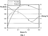
- the metal powder includes a sintering aid. Rapidly diffusing boron is added to the metal powder in an amount of about 0.1% to less than 0.3% total metal powder weight to improve pore structure by forming more spherical pore shapes within the sintered body. In one example, boron in an amount of approximately 0.15% provided improved spherical pore shape in the resultant sintered body. If more than one powder is used to form the alloy, the boron may be added to only one metal powder, or the boron may be added to more than one or all of the powders forming the alloy. For example, a first metal powder having a 17-4PH composition may be mixed with a second metal powder having a 17-4PHB. The 17-4PHB composition is a 17-4PH composition alloyed with boron to form a total powder alloy mixture having a total boron amount from about 0.1% to less than 0.3% total metal powder weight.
- the binder may be a thermoplastic polymer powder, more particularly a plyamide nylon, and most particularly may be a polyamide powder of nylon 12 such as OGRASOL® Nylon 12 by Arkema of Paris, France.
- the binder is provided in an amount of between about 1% and about 3% by weight of the total powder mixture. A binder amount of about 1% is preferred.
- the binder has an average powder size of about 4 micrometers.
- the binder may be added as a separate powder to the alloy powder mixture, or the binder may be coated on the metal powder. In one example, the binder is coated upon a 17-4PH powder and mixed with a non-coated 17-4PHB powder to form the total powder mixture.
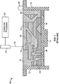
- FIG. 1 shows a side cross-sectional view of an SLS apparatus 10 and a part 15 undergoing fabrication.
- the SLS apparatus 10 includes side walls 12 and a platform or table 14.
- the table 14 may be constructed to descend incrementally within walls 12 to form a cavity for containing a powder mixture 18 to be sintered.
- a powder spreader 20 may be positioned on apparatus for speading measured layers of powder mixture 18 atop table 14 within the sintering cavity.
- Powder mixture 18 is used in the present process to build up a preform shape of the desired part 15.
- the powder mixture 18 contains a metal powder for forming the final alloy composition of the part 15 and a binder powder.
- the powder spreader 20 is used to spread a thin layer of 25.4-50.8 micrometers (0.001 inch to 0.020 inch) of powder mixture 18 atop table 14, which is initially positioned just below the top of walls 12. Table 14 may be heated with coils 16 to bring the temperature of the powder mixture 18 to a desired level below the melting point of the polymer binder constituent.
- a beam 22 from a laser 24 is scanned over the layer of powder mixture 18.
- the beam 22 may be directed by a computer processor 25 having a computer aided design (CAD) data file for part 15 so as to perform selective laser sintering of powder mixture 18.
- CAD computer aided design
- the function of the beam 22, as directed by the processor 25, is to provide precise, localized heating of powder mixture 18.
- beam 22 is provided by a laser in the infrared or near infrared region, although any focused beam of energy that is sufficiently intense to generate precise, localized heating may be used.
- a beam 22 having a power in the range of about 10W to about 35W may be used, and a beam having a power of 15W being preferred.
- the SLS process causes localized melting of the polymer constituent of a layer of powder mixture 18 as it is scanned by laser beam 22.
- the melted polymer rapidly resolidifies to bind the metal powder of the powder mixture 18 with connecting necks or bridges between metal powders.
- the table 14 is lowered a predetermined increment, a new layer of power mixture 18 is spread atop the previous layer, and the SLS process is repeated to build up part 15 layer-by-layer according to the design plan provided by computer processor 25.
- Part 15 is known in the art as a green part.
- the part 15 may be formed by alternative SLS processes.
- the green part 15 is removed from the SLS apparatus 10 and placed in a sintering furnace.
- the sintering furnace is preferably a vacuum furnace, and the source of heat may be resistance, microwave, ultrasonic or other conventional heating method as is known in the art.
- the sintering furnace is heated to first remove the binder and then to sinter the metal powder to form a net shape or near net shape part. The heating may be performed as a single or dual cycle heating process.
- the sintered part may then be subjected to secondary operations.
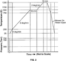
- FIG. 2 An exemplary single cycle sintering process is shown in Fig. 2 .
- the process may be performed on parts that are supported by support media.
- the support media may be casting sand, boron-nitride or other ceramic or known media in the art.
- the process may be performed on parts that are not supported by support media.
- the first step of the sintering process includes evacuating the furnace and back-filling with argon to approximately 93,3 kPa (700 torr)
- the second step includes heating the furnace to about 200°C at a rate of about 5°C/min.
- the third step includes heating from about 200°C to about 900°C at a rate of about 2°C/min.
- the furnace is then maintained at about 900°C for about 15 minutes.
- the furnace is then evacuated to approximately 40kPa (300 torr) and the temperature is increased to about 1350°C at a rate of about 2°C/min.
- the furnace is maintained at about 1350°C for about 10 minutes under vacuum.
- the furnace is then allowed to cool from about 1350°C to about 750°C with the heaters off while running chilled water through the furnace shell.
- the cooling rate is between 10°C to 20°C.
- the furnace is then back-filled with argon to approximately 93.3 kPa (700 to torr) and cooled from about 750°C to room temperature with the furnace shell cooling on and with additional cooling by an internal heat exchanger that cools the argon.
- the cooling rate is between about 10°C to about 20°C.
- the dual cycle process includes an initial browning process as shown in Fig. 3 .
- the browning process is used to remove the binder from the part 15 to form a brown part.
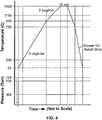
- the brown part is then subjected to a sintering process as shown in Fig. 4 .
- the sintering process further sinters and densifies the brown part to form a final part.
- the browning process is performed on green parts that may be supported by a support media.
- the support media may be casting sand, boron-nitride or other ceramic or known media in the art.
- the support media may be necessary if the binder strength and metal powder characteristics for a given part geometry is not sufficient to prevent the part from slumping during the initial binder removal.
- the first step includes evacuating the furnace and back-filling with argon to approximately 93.3 kPa (700 torr).
- the second step includes heating the furnace to about 200°C at a rate of about 5°C/min.
- the third step includes heating from about 200°C to about 900°C at a rate of about 2°C/min.
- the furnace is then maintained at about 900°C for about 15 minutes.
- the furnace is then evacuated to approximately 40 kPa (300 torr) and the temperature is increased to about 1150°C at a rate of about 2°C/min.
- the furnace is maintained at about 1150°C for about 10 minutes.
- the furnace temperature is decreased from about 1150°C to about 750°C with the heaters off and with the furnace shell heat exchanger running.
- the cooling rate is between about 10°C to about 20°C.
- the furnace is then back-filled with argon to approximately 93.3 kPa (700 torr) and decreased from about 750°C to room temperature with the furnace shell heat exchanger running, and with additional cooling by an internal heat exchanger that cools the argon.
- the cooling rate is between about 10°C to about 20°C.
- the brown part may be removed from the furnace at this time to perform secondary operations, or the brown part may be subject to the sintering process in the same furnace used for the browning process. Additionally, the brown part may be removed and processed at a later time.
- the formed brown part may be modified prior to the sintering process.
- the brown part may be machined, drilled or otherwise modified at this brown stage more easily then after the sintering process. After any modification, the brown part is then ready for the sintering process.
- the sintering process may be performed on a brown part without the need for support media since the brown part should have sufficient strength not to slump during sintering. In most cases, the presence of a support media at sintering temperatures will contaminate or negatively affect the part characteristics, but there may be cases when the presence of a support media is not harmful to the sintered part.
- the first step during the sintering step includes evacuating the furnace and back-filling with argon to approximately 93.3 kPa (700 torr).
- the second step includes heating the furnace to about 200°C at a rate of about 5°C/min.
- the third step includes heating from about 200°C to about 900°C at a rage of about 2°C/min.
- the furnace is then maintained at about 900°C for about 15 minutes.
- the furnace is then evacuated to approximately 300 torr and the temperature is increased to about 1350°C at a rate of 2°C/min.
- the furnace is maintained at about 1350°C for about 10 minutes under vacuum.
- the furnace is then allowed to cool from about 1350°C to about 750°C with the furnace shell heat exchanger on.
- the cooling rate is between about 10°C to about 20°C.
- the furnace is then back-filled with argon to approximately 93.3 kPa (700 torr) and decreased from about 750°C to room temperature with the furnace shell heat exchanger running, and with additional cooling from an internal heat exchanger cooling the argon.
- the cooling rate is between about 10°C to about 20°C.
- the sintered part is removed from the furnace.
- the sintered part may have mechanical secondary operations including machining, drilling, polishing, and surface densification performed thereupon. Additionally, the sintered part may have heat treatments including hot isostatic pressing performed thereupon.
- the results of trials performed on parts processed by the single cycle process and the dual cycle process are now discussed.
- the trials were performed on a powder mixture containing 1.0% ORGASOL® Nylon 12 having an about 4 micron average powder size and a mixture of 17-4PH powder and 17-4PHB powder that provide an overall boron percent in the metal powder of about 1.0%.
- a variety of part forms including simple flat shapes and shapes exhibiting double support bending, cantilever bending, double shear and tension were produced by SLS and subject to the following processes.
- a series of trials were performed using the single cycle process. Furnace trials were performed on both supported and non-supported parts to initially burn-off the binder and complete fmal sintering. A first group of trials were performed on un-supported shapes. The process was suitable for flat parts, but for more complex shapes, the initial profiles resulted in structural failure during binder burn-off and prior to metal powder bonding.
- a second group of single cycle trials were performed on supported shapes. Parts supported in casting sand, ceramic media and boron nitride were found dimensionally unacceptable because of bulging caused by the inability of support media to evacuate cavities that diminish as shrinkage occurs. Parts supported in sand and ceramic media were undesirable also due to deposits from products of reaction at sintering temperature, vitrification of the media, and particles of the media sticking to the sintered part. Reductions in tensile strength and fatigue resistance were noted for parts sintered in sand and boron nitride support media.
- a second series of trials were performed using the dual cycle process. Furnace trials were performed only on parts supported during the binder removal brown process. This decision was based on the necessity of support media during the first series of trials to prevent slumping. Different part shapes were processed with the dual cycle process to determine if binder burn-off could be accomplished without slump or deformation during the browning process.
- the parts were initially heated in a furnace using the browning process.
- the binder was removed from the parts and the parts became stable through particle bonding after exposure to temperatures between about 900°C and about 1150°C.
- Boron nitride media was used to support the parts in an alumina crucible during the browning cycle. Ceramic and sand media were not used after initial tests showed they produce discoloration from products of reaction at lower temperatures. Test trials showed that browning for 17-4PH alloy is initially considered the material state resulting from exposure to about 1150°C for about 10 minutes. This point is primarily chosen at the temperature prior to particle phase change, and where small particle bonding is definitely established, but before significant shrinkage begins.
- Fig. 5 also includes the properties of an example sintered part according to the invention. It should be appreciated by one of skill in the art, that instead of the cooling rate being controlled to result in a substantially pure martensitic structure, a part of a mixed martensitic and austenitic structure could initially be formed and then heat treated to form a desired martensitic structure.
- HIPping resulted in a 74% reduction in fatigue resistance. This was most probably due to a deterioration of the surface as evidenced by discoloration of the surface. HIPping did reduce pore size and the number of recognizable pores by 50% and 25% respectively. However, HIPping will not be a viable post sintering process until advances are made that preclude surface finish deterioration as the primary contributor to crack initiation.
Landscapes
- Chemical & Material Sciences (AREA)
- Engineering & Computer Science (AREA)
- Materials Engineering (AREA)
- Manufacturing & Machinery (AREA)
- Mechanical Engineering (AREA)
- Metallurgy (AREA)
- Organic Chemistry (AREA)
- Ceramic Engineering (AREA)
- Physics & Mathematics (AREA)
- General Physics & Mathematics (AREA)
- Powder Metallurgy (AREA)
Applications Claiming Priority (2)
| Application Number | Priority Date | Filing Date | Title |
|---|---|---|---|
| US11/749,864 US8017070B2 (en) | 2007-05-17 | 2007-05-17 | Direct to metal sintering of 17-4PH steel |
| PCT/US2008/062375 WO2008144199A1 (en) | 2007-05-17 | 2008-05-02 | Direct to metal sintering of 17-4ph steel |
Publications (2)
| Publication Number | Publication Date |
|---|---|
| EP2150368A1 EP2150368A1 (en) | 2010-02-10 |
| EP2150368B1 true EP2150368B1 (en) | 2012-05-16 |
Family
ID=39595524
Family Applications (1)
| Application Number | Title | Priority Date | Filing Date |
|---|---|---|---|
| EP08747469A Active EP2150368B1 (en) | 2007-05-17 | 2008-05-02 | Direct to metal sintering of 17-4ph steel |
Country Status (6)
| Country | Link |
|---|---|
| US (2) | US8017070B2 (enExample) |
| EP (1) | EP2150368B1 (enExample) |
| JP (1) | JP5502725B2 (enExample) |
| CA (2) | CA2859656C (enExample) |
| ES (1) | ES2388013T3 (enExample) |
| WO (1) | WO2008144199A1 (enExample) |
Families Citing this family (20)
| Publication number | Priority date | Publication date | Assignee | Title |
|---|---|---|---|---|
| EP1992709B1 (en) * | 2007-05-14 | 2021-09-15 | EOS GmbH Electro Optical Systems | Metal powder for use in additive manufacturing method for the production of three-dimensional objects and method using such metal powder |
| ITMO20080260A1 (it) * | 2008-10-03 | 2010-04-04 | Eurocoating S P A | Procedimento per aumentare la durezza superficiale di manufatti in acciaio |
| ITVR20100232A1 (it) * | 2010-12-09 | 2012-06-10 | Eurocoating S P A | Metodo di trattamento termico di pezzi in acciaio inossidabile indurente per precipitazione realizzati con tecniche di prototipazione rapida e simili |
| JP2013028846A (ja) * | 2011-07-29 | 2013-02-07 | Nippon Telegr & Teleph Corp <Ntt> | 遅れ破壊防止鋼材 |
| US9486963B2 (en) | 2012-12-28 | 2016-11-08 | United Technologies Corporation | Work piece having self-supporting gusset and method related thereto |
| WO2015006447A1 (en) | 2013-07-10 | 2015-01-15 | Alcoa Inc. | Methods for producing forged products and other worked products |
| JP2016108668A (ja) * | 2014-12-05 | 2016-06-20 | 株式会社日立製作所 | 複合部材および複合部材の製造方法 |
| DE102015201775A1 (de) * | 2015-02-02 | 2016-08-04 | Gkn Sinter Metals Engineering Gmbh | Verfahren und Vorrichtung zur additiven Herstellung von Bauteilen |
| CZ306020B6 (cs) | 2015-03-10 | 2016-06-22 | Západočeská Univerzita V Plzni | Způsob výroby ledeburitických vysokolegovaných ocelí tepelným zpracováním |
| WO2017105506A1 (en) | 2015-12-18 | 2017-06-22 | Hewlett-Packard Development Company, L.P. | Extraction of digitally printed build material |
| CA3011463C (en) * | 2016-01-14 | 2020-07-07 | Arconic Inc. | Methods for producing forged products and other worked products |
| DE112017001196T5 (de) * | 2016-03-09 | 2018-11-22 | Panasonic Intellectual Property Management Co., Ltd. | Verfahren zur Herstellung eines dreidimensionalen Formgegenstandes |
| PL232783B1 (pl) | 2016-05-16 | 2019-07-31 | Politechnika Krakowska Im Tadeusza Kosciuszki | Sposób wytwarzania elementów spiekanych o osnowie żelaza lub jego stopów |
| US10744563B2 (en) | 2016-10-17 | 2020-08-18 | The Boeing Company | 3D printing of an object from powdered material using pressure waves |
| CN106735241B (zh) * | 2016-12-29 | 2018-09-25 | 西安铂力特增材技术股份有限公司 | 一种加强型树脂光固化成形方法 |
| US11407034B2 (en) | 2017-07-06 | 2022-08-09 | OmniTek Technology Ltda. | Selective laser melting system and method of using same |
| CN109550954A (zh) * | 2018-12-20 | 2019-04-02 | 西安铂力特增材技术股份有限公司 | 一种热作模具钢的激光选区熔化成形方法 |
| EP4308868A4 (en) * | 2021-03-16 | 2025-01-22 | DSB Technologies, LLC | SHELVING SYSTEM FOR USE IN CONTINUOUS SINTERING FURNACES |
| DE102021203476A1 (de) | 2021-04-08 | 2022-10-13 | Volkswagen Aktiengesellschaft | Verfahren zur Herstellung eines hoch- oder höchstfesten Bauteils |
| CN113477928A (zh) * | 2021-07-06 | 2021-10-08 | 西安建筑科技大学 | 一种高强、高韧马氏体沉淀硬化不锈钢的制备方法 |
Family Cites Families (19)
| Publication number | Priority date | Publication date | Assignee | Title |
|---|---|---|---|---|
| US3352666A (en) * | 1964-11-27 | 1967-11-14 | Xaloy Inc | Precipitation hardening stainless steel alloy |
| JPS62250102A (ja) * | 1986-04-23 | 1987-10-31 | Hitachi Metals Ltd | 超硬合金又はサ−メツト合金物品の製造法 |
| US4849164A (en) * | 1988-02-29 | 1989-07-18 | General Motors Corporation | Method of producing iron powder article |
| US5745834A (en) | 1995-09-19 | 1998-04-28 | Rockwell International Corporation | Free form fabrication of metallic components |
| JPH11315304A (ja) * | 1998-05-07 | 1999-11-16 | Injex:Kk | 焼結体の製造方法 |
| JP2000038603A (ja) * | 1998-07-17 | 2000-02-08 | Yamaha Corp | 焼結品の製造方法 |
| US6042780A (en) | 1998-12-15 | 2000-03-28 | Huang; Xiaodi | Method for manufacturing high performance components |
| TW533105B (en) * | 1999-10-20 | 2003-05-21 | Injex Corp | Method of producing watchband parts |
| FR2811922B1 (fr) | 2000-07-20 | 2003-01-10 | Optoform Sarl Procedes De Prot | Composition de pate chargee de poudre metallique, procede d'obtention de produits metalliques a partir de ladite composition, et produit metallique obtenu selon ledit procede |
| SE520974C2 (sv) * | 2001-05-11 | 2003-09-16 | Iuc Karlskoga Ab | Sätt vid friformning av metallpulver och metallpulverblandning |
| JP2003013107A (ja) * | 2001-07-06 | 2003-01-15 | Nippon Piston Ring Co Ltd | 三次元形状焼結部品の製造方法 |
| US6770114B2 (en) | 2001-12-19 | 2004-08-03 | Honeywell International Inc. | Densified sintered powder and method |
| US6814926B2 (en) | 2003-03-19 | 2004-11-09 | 3D Systems Inc. | Metal powder composition for laser sintering |
| US7034246B2 (en) | 2004-08-10 | 2006-04-25 | The Boeing Company | Selective laser sintering reduced volume feed mechanism |
| WO2006041118A1 (ja) * | 2004-10-15 | 2006-04-20 | Taisei Kogyo Co., Ltd. | 多孔質焼結体の製造方法、多孔質焼結成形材料及び多孔質焼結体 |
| JP2006165300A (ja) * | 2004-12-08 | 2006-06-22 | Neomax Co Ltd | 希土類焼結磁石の製造方法 |
| JP2007016312A (ja) * | 2005-06-07 | 2007-01-25 | Hiroshima Industrial Promotion Organization | 焼結体形成方法 |
| US20060285989A1 (en) * | 2005-06-20 | 2006-12-21 | Hoeganaes Corporation | Corrosion resistant metallurgical powder compositions, methods, and compacted articles |
| JP4751159B2 (ja) * | 2005-09-15 | 2011-08-17 | 住友電工焼結合金株式会社 | 焼結体の製造方法 |
-
2007
- 2007-05-17 US US11/749,864 patent/US8017070B2/en active Active
-
2008
- 2008-05-02 CA CA2859656A patent/CA2859656C/en active Active
- 2008-05-02 EP EP08747469A patent/EP2150368B1/en active Active
- 2008-05-02 JP JP2010508490A patent/JP5502725B2/ja active Active
- 2008-05-02 CA CA2686261A patent/CA2686261C/en active Active
- 2008-05-02 WO PCT/US2008/062375 patent/WO2008144199A1/en not_active Ceased
- 2008-05-02 ES ES08747469T patent/ES2388013T3/es active Active
-
2011
- 2011-08-05 US US13/198,922 patent/US20110286874A1/en not_active Abandoned
Also Published As
| Publication number | Publication date |
|---|---|
| US8017070B2 (en) | 2011-09-13 |
| CA2686261C (en) | 2014-10-21 |
| US20110286874A1 (en) | 2011-11-24 |
| JP2010527409A (ja) | 2010-08-12 |
| CA2859656A1 (en) | 2008-11-27 |
| CA2686261A1 (en) | 2008-11-27 |
| EP2150368A1 (en) | 2010-02-10 |
| US20090208361A1 (en) | 2009-08-20 |
| ES2388013T3 (es) | 2012-10-05 |
| CA2859656C (en) | 2019-07-02 |
| WO2008144199A1 (en) | 2008-11-27 |
| JP5502725B2 (ja) | 2014-05-28 |
Similar Documents
| Publication | Publication Date | Title |
|---|---|---|
| EP2150368B1 (en) | Direct to metal sintering of 17-4ph steel | |
| Mahale | Electron beam melting of advanced materials and structures | |
| EP0764487B1 (en) | Free form fabrication of metallic components | |
| US20050112015A1 (en) | Laser sintered titanium alloy and direct metal fabrication method of making the same | |
| CN110418688B (zh) | 高碳含量钴基合金 | |
| JP2023002601A5 (enExample) | ||
| US20140295087A1 (en) | Method for additively manufacturing an article made of a difficult-to-weld material | |
| WO2004094089A1 (en) | Metal powder composition for laser sintering | |
| CA2588498A1 (en) | Method of making metallic composite foam components | |
| US6761852B2 (en) | Forming complex-shaped aluminum components | |
| JPH09509101A (ja) | 反応性メルトの永久金型鋳造 | |
| SE541903C2 (en) | High hardness 3d printed steel product | |
| Lü et al. | Selective laser sintering | |
| JP4133078B2 (ja) | 繊維強化金属の製造方法 | |
| Babaghorbani et al. | Enhancing the mechanical response of a lead-free solder using an energy-efficient microwave sintering route | |
| Ley | Binder Jet Printing of a Low-Cost Tool Steel Powder | |
| CN120002003B (zh) | 一种Al-Si-Mg系合金的电子束选区熔化增材制造方法 | |
| Li et al. | Design and fabrication of materials for Laser Shape Deposition Manufacturing | |
| Shi et al. | Large-scale equipment and higher performance materials for laser additive manufacturing | |
| EP4271530A1 (en) | High density aluminum parts from additive manufacturing | |
| Turker et al. | Full Density & Alternative Consolidation II: Rapid Prototyping of Inconel Alloys by Direct Metal Laser Sintering and Three Dimensional Printing | |
| Vogt et al. | Net-Shape Technology | |
| Pohl et al. | Sintering: Improving Mechanical Properties of Direct Metal Laser Sintered Parts by Heat Treatment | |
| Mirzababaei et al. | INTRODUCTION A Review on Binder Jet Additive Manufacturing of 316L stainless Steel | |
| JPH05245609A (ja) | 急冷凝固合金粉末を用いた高強度構造部材の製造方法 |
Legal Events
| Date | Code | Title | Description |
|---|---|---|---|
| PUAI | Public reference made under article 153(3) epc to a published international application that has entered the european phase |
Free format text: ORIGINAL CODE: 0009012 |
|
| 17P | Request for examination filed |
Effective date: 20091207 |
|
| AK | Designated contracting states |
Kind code of ref document: A1 Designated state(s): AT BE BG CH CY CZ DE DK EE ES FI FR GB GR HR HU IE IS IT LI LT LU LV MC MT NL NO PL PT RO SE SI SK TR |
|
| AX | Request for extension of the european patent |
Extension state: AL BA MK RS |
|
| RIN1 | Information on inventor provided before grant (corrected) |
Inventor name: AKE, BRYAN E. Inventor name: NORD, RICHARD J. Inventor name: LOW, STEVEN C Inventor name: WILLIAMS, REID W. Inventor name: CLARK, JERRY G. Inventor name: THOMPSON, BLAIR E. Inventor name: MUYLAERT, NEAL W. |
|
| DAX | Request for extension of the european patent (deleted) | ||
| 17Q | First examination report despatched |
Effective date: 20110210 |
|
| GRAP | Despatch of communication of intention to grant a patent |
Free format text: ORIGINAL CODE: EPIDOSNIGR1 |
|
| GRAS | Grant fee paid |
Free format text: ORIGINAL CODE: EPIDOSNIGR3 |
|
| GRAA | (expected) grant |
Free format text: ORIGINAL CODE: 0009210 |
|
| AK | Designated contracting states |
Kind code of ref document: B1 Designated state(s): AT BE BG CH CY CZ DE DK EE ES FI FR GB GR HR HU IE IS IT LI LT LU LV MC MT NL NO PL PT RO SE SI SK TR |
|
| REG | Reference to a national code |
Ref country code: GB Ref legal event code: FG4D |
|
| REG | Reference to a national code |
Ref country code: CH Ref legal event code: EP |
|
| REG | Reference to a national code |
Ref country code: AT Ref legal event code: REF Ref document number: 557801 Country of ref document: AT Kind code of ref document: T Effective date: 20120615 |
|
| REG | Reference to a national code |
Ref country code: IE Ref legal event code: FG4D |
|
| REG | Reference to a national code |
Ref country code: DE Ref legal event code: R096 Ref document number: 602008015672 Country of ref document: DE Effective date: 20120712 |
|
| REG | Reference to a national code |
Ref country code: NL Ref legal event code: VDEP Effective date: 20120516 |
|
| REG | Reference to a national code |
Ref country code: ES Ref legal event code: FG2A Ref document number: 2388013 Country of ref document: ES Kind code of ref document: T3 Effective date: 20121005 |
|
| REG | Reference to a national code |
Ref country code: LT Ref legal event code: MG4D Effective date: 20120516 |
|
| PG25 | Lapsed in a contracting state [announced via postgrant information from national office to epo] |
Ref country code: LT Free format text: LAPSE BECAUSE OF FAILURE TO SUBMIT A TRANSLATION OF THE DESCRIPTION OR TO PAY THE FEE WITHIN THE PRESCRIBED TIME-LIMIT Effective date: 20120516 Ref country code: SE Free format text: LAPSE BECAUSE OF FAILURE TO SUBMIT A TRANSLATION OF THE DESCRIPTION OR TO PAY THE FEE WITHIN THE PRESCRIBED TIME-LIMIT Effective date: 20120516 Ref country code: FI Free format text: LAPSE BECAUSE OF FAILURE TO SUBMIT A TRANSLATION OF THE DESCRIPTION OR TO PAY THE FEE WITHIN THE PRESCRIBED TIME-LIMIT Effective date: 20120516 Ref country code: PL Free format text: LAPSE BECAUSE OF FAILURE TO SUBMIT A TRANSLATION OF THE DESCRIPTION OR TO PAY THE FEE WITHIN THE PRESCRIBED TIME-LIMIT Effective date: 20120516 Ref country code: NO Free format text: LAPSE BECAUSE OF FAILURE TO SUBMIT A TRANSLATION OF THE DESCRIPTION OR TO PAY THE FEE WITHIN THE PRESCRIBED TIME-LIMIT Effective date: 20120816 Ref country code: CY Free format text: LAPSE BECAUSE OF FAILURE TO SUBMIT A TRANSLATION OF THE DESCRIPTION OR TO PAY THE FEE WITHIN THE PRESCRIBED TIME-LIMIT Effective date: 20120516 Ref country code: IS Free format text: LAPSE BECAUSE OF FAILURE TO SUBMIT A TRANSLATION OF THE DESCRIPTION OR TO PAY THE FEE WITHIN THE PRESCRIBED TIME-LIMIT Effective date: 20120916 |
|
| REG | Reference to a national code |
Ref country code: AT Ref legal event code: MK05 Ref document number: 557801 Country of ref document: AT Kind code of ref document: T Effective date: 20120516 |
|
| PG25 | Lapsed in a contracting state [announced via postgrant information from national office to epo] |
Ref country code: GR Free format text: LAPSE BECAUSE OF FAILURE TO SUBMIT A TRANSLATION OF THE DESCRIPTION OR TO PAY THE FEE WITHIN THE PRESCRIBED TIME-LIMIT Effective date: 20120817 Ref country code: LV Free format text: LAPSE BECAUSE OF FAILURE TO SUBMIT A TRANSLATION OF THE DESCRIPTION OR TO PAY THE FEE WITHIN THE PRESCRIBED TIME-LIMIT Effective date: 20120516 Ref country code: SI Free format text: LAPSE BECAUSE OF FAILURE TO SUBMIT A TRANSLATION OF THE DESCRIPTION OR TO PAY THE FEE WITHIN THE PRESCRIBED TIME-LIMIT Effective date: 20120516 Ref country code: PT Free format text: LAPSE BECAUSE OF FAILURE TO SUBMIT A TRANSLATION OF THE DESCRIPTION OR TO PAY THE FEE WITHIN THE PRESCRIBED TIME-LIMIT Effective date: 20120917 Ref country code: HR Free format text: LAPSE BECAUSE OF FAILURE TO SUBMIT A TRANSLATION OF THE DESCRIPTION OR TO PAY THE FEE WITHIN THE PRESCRIBED TIME-LIMIT Effective date: 20120516 |
|
| PG25 | Lapsed in a contracting state [announced via postgrant information from national office to epo] |
Ref country code: BE Free format text: LAPSE BECAUSE OF FAILURE TO SUBMIT A TRANSLATION OF THE DESCRIPTION OR TO PAY THE FEE WITHIN THE PRESCRIBED TIME-LIMIT Effective date: 20120516 |
|
| PG25 | Lapsed in a contracting state [announced via postgrant information from national office to epo] |
Ref country code: DK Free format text: LAPSE BECAUSE OF FAILURE TO SUBMIT A TRANSLATION OF THE DESCRIPTION OR TO PAY THE FEE WITHIN THE PRESCRIBED TIME-LIMIT Effective date: 20120516 Ref country code: CZ Free format text: LAPSE BECAUSE OF FAILURE TO SUBMIT A TRANSLATION OF THE DESCRIPTION OR TO PAY THE FEE WITHIN THE PRESCRIBED TIME-LIMIT Effective date: 20120516 Ref country code: EE Free format text: LAPSE BECAUSE OF FAILURE TO SUBMIT A TRANSLATION OF THE DESCRIPTION OR TO PAY THE FEE WITHIN THE PRESCRIBED TIME-LIMIT Effective date: 20120516 Ref country code: AT Free format text: LAPSE BECAUSE OF FAILURE TO SUBMIT A TRANSLATION OF THE DESCRIPTION OR TO PAY THE FEE WITHIN THE PRESCRIBED TIME-LIMIT Effective date: 20120516 Ref country code: NL Free format text: LAPSE BECAUSE OF FAILURE TO SUBMIT A TRANSLATION OF THE DESCRIPTION OR TO PAY THE FEE WITHIN THE PRESCRIBED TIME-LIMIT Effective date: 20120516 Ref country code: RO Free format text: LAPSE BECAUSE OF FAILURE TO SUBMIT A TRANSLATION OF THE DESCRIPTION OR TO PAY THE FEE WITHIN THE PRESCRIBED TIME-LIMIT Effective date: 20120516 Ref country code: SK Free format text: LAPSE BECAUSE OF FAILURE TO SUBMIT A TRANSLATION OF THE DESCRIPTION OR TO PAY THE FEE WITHIN THE PRESCRIBED TIME-LIMIT Effective date: 20120516 |
|
| PG25 | Lapsed in a contracting state [announced via postgrant information from national office to epo] |
Ref country code: IT Free format text: LAPSE BECAUSE OF FAILURE TO SUBMIT A TRANSLATION OF THE DESCRIPTION OR TO PAY THE FEE WITHIN THE PRESCRIBED TIME-LIMIT Effective date: 20120516 |
|
| PLBE | No opposition filed within time limit |
Free format text: ORIGINAL CODE: 0009261 |
|
| STAA | Information on the status of an ep patent application or granted ep patent |
Free format text: STATUS: NO OPPOSITION FILED WITHIN TIME LIMIT |
|
| 26N | No opposition filed |
Effective date: 20130219 |
|
| REG | Reference to a national code |
Ref country code: DE Ref legal event code: R097 Ref document number: 602008015672 Country of ref document: DE Effective date: 20130219 |
|
| PG25 | Lapsed in a contracting state [announced via postgrant information from national office to epo] |
Ref country code: BG Free format text: LAPSE BECAUSE OF FAILURE TO SUBMIT A TRANSLATION OF THE DESCRIPTION OR TO PAY THE FEE WITHIN THE PRESCRIBED TIME-LIMIT Effective date: 20120816 |
|
| PG25 | Lapsed in a contracting state [announced via postgrant information from national office to epo] |
Ref country code: MC Free format text: LAPSE BECAUSE OF FAILURE TO SUBMIT A TRANSLATION OF THE DESCRIPTION OR TO PAY THE FEE WITHIN THE PRESCRIBED TIME-LIMIT Effective date: 20120516 |
|
| REG | Reference to a national code |
Ref country code: CH Ref legal event code: PL |
|
| PG25 | Lapsed in a contracting state [announced via postgrant information from national office to epo] |
Ref country code: CH Free format text: LAPSE BECAUSE OF NON-PAYMENT OF DUE FEES Effective date: 20130531 Ref country code: LI Free format text: LAPSE BECAUSE OF NON-PAYMENT OF DUE FEES Effective date: 20130531 |
|
| REG | Reference to a national code |
Ref country code: IE Ref legal event code: MM4A |
|
| PG25 | Lapsed in a contracting state [announced via postgrant information from national office to epo] |
Ref country code: IE Free format text: LAPSE BECAUSE OF NON-PAYMENT OF DUE FEES Effective date: 20130502 |
|
| PG25 | Lapsed in a contracting state [announced via postgrant information from national office to epo] |
Ref country code: MT Free format text: LAPSE BECAUSE OF FAILURE TO SUBMIT A TRANSLATION OF THE DESCRIPTION OR TO PAY THE FEE WITHIN THE PRESCRIBED TIME-LIMIT Effective date: 20120516 |
|
| PG25 | Lapsed in a contracting state [announced via postgrant information from national office to epo] |
Ref country code: TR Free format text: LAPSE BECAUSE OF FAILURE TO SUBMIT A TRANSLATION OF THE DESCRIPTION OR TO PAY THE FEE WITHIN THE PRESCRIBED TIME-LIMIT Effective date: 20120516 |
|
| PG25 | Lapsed in a contracting state [announced via postgrant information from national office to epo] |
Ref country code: LU Free format text: LAPSE BECAUSE OF NON-PAYMENT OF DUE FEES Effective date: 20130502 Ref country code: HU Free format text: LAPSE BECAUSE OF FAILURE TO SUBMIT A TRANSLATION OF THE DESCRIPTION OR TO PAY THE FEE WITHIN THE PRESCRIBED TIME-LIMIT; INVALID AB INITIO Effective date: 20080502 |
|
| REG | Reference to a national code |
Ref country code: FR Ref legal event code: PLFP Year of fee payment: 9 |
|
| REG | Reference to a national code |
Ref country code: FR Ref legal event code: PLFP Year of fee payment: 10 |
|
| REG | Reference to a national code |
Ref country code: FR Ref legal event code: PLFP Year of fee payment: 11 |
|
| P01 | Opt-out of the competence of the unified patent court (upc) registered |
Effective date: 20230516 |
|
| PGFP | Annual fee paid to national office [announced via postgrant information from national office to epo] |
Ref country code: DE Payment date: 20250529 Year of fee payment: 18 |
|
| PGFP | Annual fee paid to national office [announced via postgrant information from national office to epo] |
Ref country code: ES Payment date: 20250602 Year of fee payment: 18 Ref country code: GB Payment date: 20250527 Year of fee payment: 18 |
|
| PGFP | Annual fee paid to national office [announced via postgrant information from national office to epo] |
Ref country code: FR Payment date: 20250526 Year of fee payment: 18 |