EP2148405A2 - Informationsumschreibungsvorrichtung, Programm, Batterie, Batterieladegerät und Ladesystem - Google Patents
Informationsumschreibungsvorrichtung, Programm, Batterie, Batterieladegerät und Ladesystem Download PDFInfo
- Publication number
- EP2148405A2 EP2148405A2 EP09009433A EP09009433A EP2148405A2 EP 2148405 A2 EP2148405 A2 EP 2148405A2 EP 09009433 A EP09009433 A EP 09009433A EP 09009433 A EP09009433 A EP 09009433A EP 2148405 A2 EP2148405 A2 EP 2148405A2
- Authority
- EP
- European Patent Office
- Prior art keywords
- information
- battery
- unit
- rewrite
- battery charger
- Prior art date
- Legal status (The legal status is an assumption and is not a legal conclusion. Google has not performed a legal analysis and makes no representation as to the accuracy of the status listed.)
- Granted
Links
Images




Classifications
-
- H—ELECTRICITY
- H01—ELECTRIC ELEMENTS
- H01M—PROCESSES OR MEANS, e.g. BATTERIES, FOR THE DIRECT CONVERSION OF CHEMICAL ENERGY INTO ELECTRICAL ENERGY
- H01M10/00—Secondary cells; Manufacture thereof
- H01M10/42—Methods or arrangements for servicing or maintenance of secondary cells or secondary half-cells
- H01M10/425—Structural combination with electronic components, e.g. electronic circuits integrated to the outside of the casing
-
- H—ELECTRICITY
- H02—GENERATION; CONVERSION OR DISTRIBUTION OF ELECTRIC POWER
- H02J—ELECTRIC POWER NETWORKS; CIRCUIT ARRANGEMENTS OR SYSTEMS FOR SUPPLYING OR DISTRIBUTING ELECTRIC POWER; SYSTEMS FOR STORING ELECTRIC ENERGY
- H02J7/00—Circuit arrangements for charging or discharging batteries or for supplying loads from batteries
- H02J7/40—Circuit arrangements for charging or discharging batteries or for supplying loads from batteries characterised by the exchange of charge or discharge related data
- H02J7/44—Circuit arrangements for charging or discharging batteries or for supplying loads from batteries characterised by the exchange of charge or discharge related data between battery management systems and power sources
-
- H—ELECTRICITY
- H01—ELECTRIC ELEMENTS
- H01M—PROCESSES OR MEANS, e.g. BATTERIES, FOR THE DIRECT CONVERSION OF CHEMICAL ENERGY INTO ELECTRICAL ENERGY
- H01M10/00—Secondary cells; Manufacture thereof
- H01M10/42—Methods or arrangements for servicing or maintenance of secondary cells or secondary half-cells
- H01M10/46—Accumulators structurally combined with charging apparatus
-
- H—ELECTRICITY
- H02—GENERATION; CONVERSION OR DISTRIBUTION OF ELECTRIC POWER
- H02J—ELECTRIC POWER NETWORKS; CIRCUIT ARRANGEMENTS OR SYSTEMS FOR SUPPLYING OR DISTRIBUTING ELECTRIC POWER; SYSTEMS FOR STORING ELECTRIC ENERGY
- H02J7/00—Circuit arrangements for charging or discharging batteries or for supplying loads from batteries
- H02J7/485—Circuit arrangements for charging or discharging batteries or for supplying loads from batteries with provisions for charging different types of batteries
-
- H—ELECTRICITY
- H01—ELECTRIC ELEMENTS
- H01M—PROCESSES OR MEANS, e.g. BATTERIES, FOR THE DIRECT CONVERSION OF CHEMICAL ENERGY INTO ELECTRICAL ENERGY
- H01M10/00—Secondary cells; Manufacture thereof
- H01M10/42—Methods or arrangements for servicing or maintenance of secondary cells or secondary half-cells
- H01M10/425—Structural combination with electronic components, e.g. electronic circuits integrated to the outside of the casing
- H01M2010/4278—Systems for data transfer from batteries, e.g. transfer of battery parameters to a controller, data transferred between battery controller and main controller
-
- Y—GENERAL TAGGING OF NEW TECHNOLOGICAL DEVELOPMENTS; GENERAL TAGGING OF CROSS-SECTIONAL TECHNOLOGIES SPANNING OVER SEVERAL SECTIONS OF THE IPC; TECHNICAL SUBJECTS COVERED BY FORMER USPC CROSS-REFERENCE ART COLLECTIONS [XRACs] AND DIGESTS
- Y02—TECHNOLOGIES OR APPLICATIONS FOR MITIGATION OR ADAPTATION AGAINST CLIMATE CHANGE
- Y02E—REDUCTION OF GREENHOUSE GAS [GHG] EMISSIONS, RELATED TO ENERGY GENERATION, TRANSMISSION OR DISTRIBUTION
- Y02E60/00—Enabling technologies; Technologies with a potential or indirect contribution to GHG emissions mitigation
- Y02E60/10—Energy storage using batteries
Definitions
- the present invention relates to a technique for rewriting information stored in a battery and a battery charger.
- the battery and the battery charger respectively have storage media, where charge characteristic data of the battery are stored.
- charge characteristics required are diversified depending on how the battery is used. Because of this, it is preferable that the charge characteristic data, which are stored in the battery and the battery charger, can be changed as appropriate.
- a user connects a battery and a battery charger separately to a terminal device connected to the Internet. Then, the user operates the terminal device to obtain charge characteristic data from a server device on the Internet, and rewrites data stored in the battery or the battery charger, which are connected to the terminal device, based on the data obtained from the server device.
- An information rewriting device includes a first storage unit, a second storage unit, and at least one rewrite unit.
- the first storage unit is provided in a battery, and rewritably stores a first information.
- the second storage unit is provided in a battery charger, and rewritably stores a second information.
- the battery charger charges the battery by being electrically connected to the battery detachably therefrom.
- the at least one rewrite unit is provided in at least one of the battery and the battery charger.
- the at least one rewrite unit rewrites one information out of the first information stored in the first storage unit and the second information stored in the second storage unit based on the other information out of the first information and the second information.
- the information rewriting device configured as above, a user is not required to separately carry out an operation to rewrite the information since one of the first information stored in the battery and the second information stored in the battery charger is rewritten based on the other only by electrically connecting the battery and the battery charger.
- the at least one rewrite unit may be two rewrite units, which may include a first rewrite unit, which is provided in the battery and rewrites the second information stored in the second storage unit provided in the battery charger, and a second rewrite unit, which is provided in the battery charger and rewrites the first information stored in the first storage unit provided in the battery.
- the information rewriting device may include a first determination unit, a first operation inhibiting unit, a second determination unit, and a second operation inhibiting unit.
- the first determination unit is provided in the battery, and determines whether or not the first information should be rewritten, based on contents of the first information and the second information.
- the first operation inhibiting unit is provided in the battery, and inhibits an operation of the first rewrite unit when the first determination unit determines that the first information should be rewritten.
- the second determination unit is provided in the battery charger, and determines whether or not the second information should be rewritten, based on contents of the first information and the second information.
- the second operation inhibiting unit is provided in the battery charger, and inhibits an operation of the second rewrite unit when the second determination unit determines that the second information should be rewritten.
- the information rewriting device configured as above can reduce a possibility that the second information may be rewritten based on the first information when the first information should be rewritten, as well as a possibility that the first information may be rewritten based on the second information when the second information should be rewritten.
- the first determination unit and the second determination unit may determine whether or not the first information should be rewritten and whether or not the second information should be rewritten in any manner. For example, in a case where the first information and the second information include an update information indicating update histories of the first information and the second information, at least one of the first determination unit and the second determination unit may refer to the update information included in the first information and the second information, and may make a determination based on the update information.
- information which should be rewritten may be identified and rewritten based on the update information included in the first information and the second information.
- the at least one rewrite unit may include a writing unit, a success determination unit, and an overwriting unit.
- the writing unit When rewriting the one information, the writing unit writes the other information into one storage area other than another storage area where the one information is stored, in the storage unit out of the first storage unit and the second storage unit where the one information is stored.
- the success determination unit determines whether or not a write by the writing unit succeeds, based at least on the other information written in the one storage area.
- the overwriting unit writes the other information written in the one storage area by the writing unit over the another storage area where the one information is stored.
- the information to be rewritten can be inhibited from being rewritten based on incomplete or erroneous information, when information transmission between the battery and the battery charger ended in failure.
- the overwriting unit may write the other information after deleting the one information, or may overwrite the one information with the other information without deleting the one information.
- the above-described information rewriting device may include at least one notification unit.
- the at least one notification unit is provided in at least one of the battery and the battery charger, and notifies a completion of a rewrite by the at least one rewrite unit when the rewrite has been completed.
- the user can easily grasp whether or not the information rewrite has been completed. This can reduce a possibility that the user may detach the battery from the battery charger although the information rewrite has not been completed yet.
- the notification unit may notify the completion of the rewrite in any manner, for example, using light, sound, vibration, display, and the like.
- the above-described information rewriting device may include a charge initiating unit.
- the charge initiating unit is provided in the battery charger, and initiates a charging of the battery after a rewrite by the at least one rewrite unit has been completed.
- the information rewriting device configured as above, electrical noise caused by electric current flowing through the battery and the battery charger for the charging can be inhibited from affecting the rewrite of the information.
- the first information may be a program executed by the computer.
- the second information may be a program executed by the computer.
- the user can easily rewrite the program executed by the computer in the battery and the program executed by the computer in the battery charger with the information rewriting device.
- the first information and the second information may be any program.
- the first information and the second information may be programs for controlling the charging of the battery by the computer in the battery and the computer in the battery charger.
- the information rewriting device may include a protocol changing unit which changes a communication protocol between the battery and the battery charger from a first protocol to a second protocol when the at least one rewrite unit rewrites the one information.
- the second protocol is configured to a protocol more appropriate to rewrite the one information than the first protocol, the one information can be preferably rewritten.
- the information rewriting device may include a protocol controlling unit which determines whether or not it is possible to change the communication protocol between the battery and the battery charger from the first protocol to the second protocol, allows the protocol changing unit to operate when the change is determined to be possible, and inhibits the protocol changing unit from operating when the change is determined to be impossible.
- a protocol controlling unit which determines whether or not it is possible to change the communication protocol between the battery and the battery charger from the first protocol to the second protocol, allows the protocol changing unit to operate when the change is determined to be possible, and inhibits the protocol changing unit from operating when the change is determined to be impossible.
- a second aspect of the present invention is a program for allowing a computer to function as a rewrite unit which rewrites one information out of a first information and a second information based on the other information out of the first information and the second information.
- the first information is stored in a first storage unit, which is provided in a battery and rewritably stores the first information.
- the second information is stored in a second storage unit, which is provided in a battery charger, which charges the battery, and rewritably stores the second information.
- the computer is enabled to function as the rewrite unit.
- the above-described computer may be a known computer or a computer preferably configured for the battery or the battery charger.
- the above-described program may be stored in a ROM or a backup RAM, which are installed in the computer, and used after being loaded to the computer from the ROM or the backup RAM, or may be used after being loaded to the computer via network. Furthermore, the above-described program may be used after being recorded in a computer-readable recording medium.
- a recording medium includes, for example, a flexible disk (FD), an optical disk (MO), a DVD, a CD-ROM, a Blu-ray disc, an HD-DVD, a hard disk, a portable semiconductor memory (e.g., a USB memory, a memory card), and the like.
- a third aspect of the present invention is a battery which includes the first storage unit and the at least one rewrite unit in the information rewriting device of the first aspect.
- a fourth aspect of the present invention is a battery charger which includes the second storage unit and the at least one rewrite unit in the information rewriting device of the first aspect.
- a fifth aspect of the present invention is a charging system which includes the battery of the third aspect and the battery charger of the fourth aspect.
- the charging system may be configured to allow the battery to be electrically connectable to the battery charger by sliding the battery on the battery charger. In this case, the user can easily rewrite the first information stored in the battery or the second information stored in the battery charger only by sliding the battery on the battery charger.
- a battery 1 is provided with an apparatus attachment portion 11 on an upper side thereof.
- the apparatus attachment portion 11 is configured to be attachable to and detachable from a battery charger by being slided on the battery charger.
- a communication connector 12 In the vicinity of the central part of the apparatus attachment portion 11, there are provided a communication connector 12 and a pair of electrode connectors 13. More specifically, the communication connector 12 is arranged between the pair of electrode connectors 13.
- the communication connector 12 is configured as a male connector, which protrudes toward an attachment direction to the battery charger.
- the pair of electrode connectors 13 is configured to allow a positive side electrode terminal and a negative side electrode terminal on the side of the battery charger to be slided inside the pair of electrode connectors 13.
- a battery charger 2 is provided with a battery attachment portion 21 and a display portion 22 on an upper side thereof.
- the battery 1 is attached to the battery attachment portion 21 with the apparatus attachment portion 11 of the battery 1 facing downward.
- the battery attachment portion 21 is configured to allow the apparatus attachment portion 11 of the battery 1 to be slided on the battery charger 2 while guiding the battery 1 along the attachment direction to the battery charger 2.
- the battery attachment portion 21 is provided with a protection cover 28, a communication connector 23, a positive side electrode terminal 24A, and a negative side electrode terminal 24B.
- the protection cover 28, which is slidably provided on the battery attachment portion 21, covers the communication connector 23, the positive side electrode terminal 24A, and the negative side electrode terminal 24B when the battery 1 is yet to be attached to the battery attachment portion 21, whereas the protection cover 28 exposes the communication connector 23, the positive side electrode terminal 24A, and the negative side electrode terminal 24B to the battery 1 when the battery 1 is attached to the battery attachment portion 21.
- the communication connector 23 is arranged between the positive side electrode terminal 24A and the negative side electrode terminal 24B.
- the communication connector 23 is configured as a female connector, which is fitted with the above-described communication connector 12 of the battery 1.
- a plurality of connection terminals which are electrically connected to a plurality of communication terminals provided in the communication connector 12, are provided inside the communication connector 23.
- the positive side electrode terminal 24A which is a plate-shaped terminal protruding upward of the battery charger 2, is guided by one of the electrode connectors 13 of the battery 1, and is electrically connected to a positive side electrode terminal 13A (see Fig. 4 ) provided inside the electrode connector 13.
- the negative side electrode terminal 24B which is a plate-shaped terminal protruding upward of the battery charger 2 just as the positive side electrode terminal 24A, is guided by the other of the electrode connectors 13 of the battery 1, and is electrically connected to a negative side electrode terminal 13B (see Fig. 4 ) provided inside the electrode connector 13.
- the display portion 22, which includes three indicator lamps 22A, 22B, and 22C, is configured to display a status of the battery 1 and the battery charger 2 with the indicator lamps 22A, 22B, and 22C. More specifically, the indicator lamps 22A and 22B are lamps for indicating a remaining amount of electric power in the battery 1, and the indicator lamp 22C is a lamp for indicating whether or not a rewrite of a program stored in the battery 1 and a rewrite of a program stored in the battery charger 2 is being carried out.
- the battery 1 is provided with a microcomputer 14.
- the microcomputer 14 which is configured as a so-called one-chip microcomputer, has at least a CPU 141, a ROM 142, a RAM 143, a non-volatile memory 144, an input/output (I/O) port 145, and a communication interface (I/F) 146 integrated thereinto.
- the non-volatile memory 144 may be any memory element as long as the same can rewrite a memory content, and it is possible to use, for example, an EEPROM and a flash memory as the non-volatile memory 144.
- a program for controlling the charging of the battery 1 (a charging control program) by the microcomputer 14 is rewritably stored.
- the charging control program includes a version information indicating an update history of the charging control program.
- the microcomputer 14 is connected to the plurality of communication terminals provided in the communication connector 12 of the battery 1. More specifically, the microcomputer 14 is connected to a temperature data terminal 12A, a data communication terminal 12B, and a GND terminal 12C.
- the temperature data terminal 12A is a terminal for outputting to the battery charger 2 an electrical signal (a temperature signal) outputted from the microcomputer 14 based on a temperature detected by a thermistor (not shown) provided in the battery 1.
- the data communication terminal 12B is a terminal for outputting a data signal outputted from the microcomputer 14 to the battery charger 2 and for inputting a data signal outputted from the battery charger 2 to the microcomputer 14.
- the GND terminal 12C is a terminal where a reference potential for communication signals transmitted between the battery 1 and the battery charger 2 is set.
- the battery 1 includes a cell portion 15, where a plurality of series-connected cells are provided. A positive side of the cell portion 15 is connected to the above-described positive side electrode terminal 13A of the battery 1 via a fuse 16, whereas a negative side of the cell portion 15 is connected to the above-described negative side electrode terminal 13B of the battery 1.
- the negative side electrode terminal 13B is electrically connected to the above-described GND terminal 12C, and sets a potential of the GND terminal 12C to a potential of a negative electrode of the cell portion 15 (i.e., a potential of a negative electrode of the battery 1).
- the battery charger 2 includes a microcomputer 25.
- the microcomputer 25, which is configured as a one-chip microcomputer just as the microcomputer 14, has at least a CPU 251, a ROM 252, a RAM 253, a non-volatile memory 254, an I/O port 255, and a communication I/F 256 integrated thereinto.
- the non-volatile memory 254 may be any memory element, just as the non-volatile memory 144, as long as the same can rewrite memory content, and it is possible to use, for example, an EEPROM and a flash memory as the non-volatile memory 254.
- a program for controlling the charging of the battery 1 (a charging control program) by the microcomputer 25 is rewritably stored.
- the charging control program includes a version information indicating an update history of the charging control program.
- the microcomputer 25 is connected to the plurality of connection terminals provided in the above-described communication connector 23 of the battery charger 2. More specifically, the microcomputer 25 is connected to a temperature data terminal 23A, a data communication terminal 23B, and a GND terminal 23C.
- the temperature data terminal 23A which is electrically connected to the temperature data terminal 12A of the battery 1 when the battery 1 is attached to the battery charger 2, is a terminal for inputting the temperature signal outputted from the microcomputer 14 of the battery 1 to the microcomputer 25.
- the data communication terminal 23B which is electrically connected to the data communication terminal 12B of the battery 1 when the battery 1 is attached to the battery charger 2, is a terminal for inputting the data signal outputted from the microcomputer 14 of the battery 1 to the microcomputer 25 and for outputting the data signal outputted from the microcomputer 25 to the microcomputer 14.
- the GND terminal 23C which is electrically connected to the GND terminal 12C of the battery 1 when the battery 1 is attached to the battery charger 2, is a terminal where the reference potential for communication signals transmitted between the battery 1 and the battery charger 2 is set.
- the battery charger 2 includes an LED 26 which is a light source of the indicator lamp 22C.
- the LED 26 is connected to the microcomputer 25 so as to be turned on and off in accordance with a command from the microcomputer 25. More specifically, in the LED 26, an anode of the LED 26 is connected to a positive electrode Vcc of a power source of the battery charger 2, and a cathode of the LED 26 is connected to the microcomputer 25.
- a plurality of LEDs, which are light sources of the indicator lamps 22A and 22B are not shown in Fig. 4 , the battery charger 2 practically includes the plurality of LEDs, which are the light sources of the indicator lamps 22A and 22B.
- the battery charger 2 includes a charging portion 27 for supplying electric power to the battery 1 to charge the battery 1. More specifically, a positive side of the charging portion 27 is connected to the above-described positive side electrode terminal 24A of the battery charger 2. That is, the positive side of the charging portion 27 is electrically connected to a positive electrode of the battery 1 (the cell portion 15) via the positive side electrode terminal 24A of the battery charger 2 and the positive side electrode terminal 13A of the battery 1 when the battery 1 is attached to the battery charger 2.
- a negative side of the charging portion 27 is connected to the above-described negative side electrode terminal 24B of the battery charger 2. That is, the negative side of the charging portion 27 is electrically connected to the negative electrode of the battery 1 (the cell portion 15) via the negative side electrode terminal 24B of the battery charger 2 and the negative side electrode terminal 13B of the battery 1 when the battery 1 is attached to the battery charger 2. Moreover, the negative side electrode terminal 24B is electrically connected to the above-described GND terminal 23C, and sets a potential of the GND terminal 23C to a potential of a negative electrode of the charging portion 27 (i.e., a potential of the negative electrode of the battery 1).
- the charging portion 27 is connected to the microcomputer 25, and configured to charge the battery 1 in accordance with a command from the microcomputer 25.
- processes according to the present invention which are executed by the CPU 141 of the battery 1 and the CPU 251 of the battery charger 2, will be described.
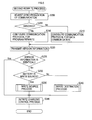
- the CPU 251 initiates a first (primary) rewrite process when detecting that the battery 1 is attached to the battery charger 2 based on the above-described temperature signal.
- a synchronization of communication with the battery 1 is initially adjusted (S100) based on a preconfigured communication protocol (a communication protocol for program rewrite) to rewrite a charging control program, which is different from a mere communication protocol for data communication.
- This communication protocol for program rewrite is so configured as to rewrite the charging control program in less time than required by the communication protocol for data communication.
- a communication protocol used to communicate with the battery 1 is configured to the communication protocol for data communication (S110), and the process is forwarded to S120 to be described below.
- the communication protocol used to communicate with the battery 1 is configured to the communication protocol for program rewrite (S115), and the battery 1 (more specifically, the CPU 141 of the battery 1) is queried for the version information of the charging control program stored in the battery 1 (S 120).
- the battery 1 is notified that the version information is not identical (S135), and then the indicator lamp 22C is lit up (S140) by turning on the LED 26.
- the lighting-up of the indicator lamp 22C enables the user to grasp that the rewrite of the charging control program is to be carried out.
- the battery 1 When the charging control program in the battery 1 is newer than the charging control program in the battery charger 2 (S145: No), the battery 1 is notified that the battery charger 2 is to be a write destination of the charging control program (S160), and after a preconfigured write destination process is executed (S165), the indicator lamp 22C is extinguished (S170) by turning off the LED 26. The extinction of the indicator lamp 22C enables the user to grasp that the rewrite of the charging control program has been completed.
- the CPU 141 of the battery 1 initiates a second (secondary) rewrite process when detecting that the battery 1 is attached to the battery charger 2 based on the above-described temperature signal.
- a synchronization of communication with the battery charger 2 is initially adjusted (S200) based on the above-described communication protocol for program rewrite.
- S200 the synchronization of communication with the battery charger 2 based on the communication protocol for program rewrite fails (S205: No)
- a communication protocol used to communicate with the battery charger 2 is configured to the communication protocol for data communication (S210), and the process is forwarded to S220 to be described below.
- a communication protocol used to communicate with the battery charger 2 is configured to the communication protocol for program rewrite (S215).
- the version information of the charging control program stored in the non-volatile memory 144 is transmitted to the battery charger 2 (S220).
- a command is initially issued to the write destination to delete a program stored in a temporary storage area (RAM) (S300) of the write destination specifying an address of the temporary storage area.
- RAM temporary storage area
- the version information of the charging control program in the non-volatile memory of the write destination is updated to the version information of the charging control program in the write source (S445), and the present process is terminated.
- one of the charging control program stored in the battery 1 and the charging control program stored in the battery charger 2 is rewritten based on the other only by attaching the battery 1 to the battery charger 2 to electrically connect the battery 1 and the battery charger 2.
- the user can easily rewrite the charging control program stored in the battery 1 and the battery charger 2 only by sliding the battery 1 on the battery charger 2 to attach the battery 1 to the battery charger 2. In short, the user can easily change charge characteristics in the battery 1 and the battery charger 2.
- the battery 1 and the battery charger 2 of the present embodiment it is determined based on the version information whether the charging control program in the battery 1 should be rewritten or the charging control program in the battery charger 2 should be rewritten, whereby a possibility that a newer charging control program may be rewritten based on an older charging control program can be reduced.
- the battery 1 of the present embodiment as long as a new charging control program is stored in the battery 1, an old charging control program stored in a battery charger can be updated only by connecting the battery 1 to the battery charger.
- an old charging control program stored in a battery can be updated only by connecting the battery to the battery charger 2.
- the charging control program in the write source is written into the temporary storage area of the write destination, and when the program has been successfully written into the temporary storage area, the program is written over the non-volatile memory of the write destination.
- the charging control program in the write destination may be rewritten based on an incomplete or erroneous charging control program caused by a failure in transmission between the battery 1 and the battery charger 2.
- the battery charger 2 of the present embodiment it is notified that the rewrite of the charging control program is in progress by keeping the indicator lamp 22C on during the rewrite of the charging control program, whereas it is notified that the rewrite of the charging control program has been completed by extinguishing the indicator lamp 22C upon completion of the rewrite of the charging control program, whereby the user can easily grasp whether or not the rewrite of the charging control program has been completed.
- This can reduce a possibility that the user may detach the battery 1 from the battery charger 2 although the rewrite of the charging control program has not been completed yet.
- battery charging is initiated after the rewrite of the charging control program has been completed, which can reduce a possibility that electrical noise caused by electric current flowing through the battery 1 and the battery charger 2 for the charging may affect the rewrite of the charging control program.
- the completion of the rewrite of the charging control program is notified by extinguishing the lighted indicator lamp 22C in the above embodiment, it may be notified by sound, vibration, display, and the like.
- the lamp for notifying that the rewrite of the charging control program has been completed is provided only in the battery charger 2 in the above embodiment, such a lamp may be also provided in the battery 1. In this case, the indicator lamp 22C may be eliminated from the battery charger 2.
- both of the battery 1 and the battery charger 2 are configured to be the write source and the write destination of the charging control program in the above embodiment, the battery 1 and the battery charger 2 may be configured so that one of the battery 1 and the battery charger 2 is to be the write source only and the other of the battery 1 and the battery charger 2 is to be the write destination only.
- the charging control program is rewritten in the above embodiment, a program, data, and the like other than the charging control program may be rewritten. It is explicitly stated that all features disclosed in the description and/or the claims are intended to be disclosed separately and independently from each other for the purpose of original disclosure as well as for the purpose of restricting the claimed invention independent of the composition of the features in the embodiments and/or the claims. It is explicitly stated that all value ranges or indications of groups of entities disclose every possible intermediate value or intermediate entity for the purpose of original disclosure as well as for the purpose of restricting the claimed invention, in particular as limits of value ranges.
Landscapes
- Engineering & Computer Science (AREA)
- Manufacturing & Machinery (AREA)
- Chemical & Material Sciences (AREA)
- Chemical Kinetics & Catalysis (AREA)
- Electrochemistry (AREA)
- General Chemical & Material Sciences (AREA)
- Power Engineering (AREA)
- Microelectronics & Electronic Packaging (AREA)
- Charge And Discharge Circuits For Batteries Or The Like (AREA)
- Secondary Cells (AREA)
- Stored Programmes (AREA)
Applications Claiming Priority (1)
| Application Number | Priority Date | Filing Date | Title |
|---|---|---|---|
| JP2008192456A JP2010033168A (ja) | 2008-07-25 | 2008-07-25 | 充電システム、バッテリ、充電装置、及びプログラム |
Publications (3)
| Publication Number | Publication Date |
|---|---|
| EP2148405A2 true EP2148405A2 (de) | 2010-01-27 |
| EP2148405A3 EP2148405A3 (de) | 2011-09-07 |
| EP2148405B1 EP2148405B1 (de) | 2019-05-15 |
Family
ID=41278476
Family Applications (1)
| Application Number | Title | Priority Date | Filing Date |
|---|---|---|---|
| EP09009433.5A Not-in-force EP2148405B1 (de) | 2008-07-25 | 2009-07-21 | Ein Ladesystem, das zum Umschreiben von Informationen geeignet ist |
Country Status (5)
| Country | Link |
|---|---|
| US (1) | US20100019719A1 (de) |
| EP (1) | EP2148405B1 (de) |
| JP (1) | JP2010033168A (de) |
| CN (1) | CN101635469B (de) |
| RU (1) | RU2522315C2 (de) |
Cited By (3)
| Publication number | Priority date | Publication date | Assignee | Title |
|---|---|---|---|---|
| CN104995814A (zh) * | 2012-12-28 | 2015-10-21 | 株式会社理光 | 电池充电器、电池充电系统和电池充电方法 |
| EP2654169A3 (de) * | 2012-04-18 | 2015-12-02 | PHOENIX CONTACT GmbH & Co. KG | Ladevorrichtung für ein Elektrofahrzeug |
| EP3316388A1 (de) * | 2016-10-26 | 2018-05-02 | Makita Corporation | Batteriepack und verfahren zum schreiben von daten zu dem batteriepack |
Families Citing this family (10)
| Publication number | Priority date | Publication date | Assignee | Title |
|---|---|---|---|---|
| US9152408B2 (en) * | 2010-06-23 | 2015-10-06 | Toyota Jidosha Kabushiki Kaisha | Program update device |
| US9543783B2 (en) * | 2011-04-12 | 2017-01-10 | Go-Tech Energy Co., Ltd. | Charging module and rechargeable battery assembly for electric vehicle |
| CN107257152B (zh) * | 2011-04-28 | 2021-04-09 | 佐尔循环公司 | 用于更新数据、操作参数和/或软件的系统 |
| JP5956245B2 (ja) * | 2012-05-11 | 2016-07-27 | 株式会社マキタ | バッテリパック及び電動機器システム |
| JP2015053754A (ja) * | 2013-09-05 | 2015-03-19 | 日立マクセル株式会社 | 非接触充電システム及び二次電池パック |
| JP6203664B2 (ja) * | 2014-02-26 | 2017-09-27 | 株式会社マキタ | 充電器 |
| US9917457B2 (en) | 2015-02-02 | 2018-03-13 | Black & Decker Inc. | Power tool with USB connection |
| CN109901856B (zh) * | 2017-12-10 | 2022-11-25 | 启美科技(江苏)有限公司 | 一种机器人固件升级设备 |
| JP7396386B2 (ja) * | 2022-03-23 | 2023-12-12 | いすゞ自動車株式会社 | バッテリ管理装置 |
| KR20250007351A (ko) * | 2023-07-05 | 2025-01-14 | 삼성에스디아이 주식회사 | 배터리 시스템 및 이의 충방전 제어 방법 |
Family Cites Families (30)
| Publication number | Priority date | Publication date | Assignee | Title |
|---|---|---|---|---|
| JPS63305444A (ja) * | 1987-06-08 | 1988-12-13 | Mitsubishi Electric Corp | 記憶装置 |
| JPH0595324A (ja) * | 1991-10-03 | 1993-04-16 | Matsushita Electric Ind Co Ltd | 携帯電話装置 |
| JPH06343205A (ja) * | 1993-06-01 | 1994-12-13 | Nissan Motor Co Ltd | 電気自動車の充電装置 |
| US5596567A (en) * | 1995-03-31 | 1997-01-21 | Motorola, Inc. | Wireless battery charging system |
| JPH11282656A (ja) * | 1998-03-30 | 1999-10-15 | Brother Ind Ltd | プログラム書換装置、ネットワークシステム、及び記憶媒体 |
| US6018227A (en) * | 1998-06-22 | 2000-01-25 | Stryker Corporation | Battery charger especially useful with sterilizable, rechargeable battery packs |
| JP3610260B2 (ja) * | 1999-05-20 | 2005-01-12 | 株式会社ソニー・コンピュータエンタテインメント | 送受信システム、充電装置、携帯情報端末及びデータ送受信方法 |
| JP2001034460A (ja) * | 1999-07-19 | 2001-02-09 | Matsushita Electric Ind Co Ltd | 画像処理システムおよびそのプログラムの自動アップデート方法 |
| JP3474850B2 (ja) * | 2000-01-12 | 2003-12-08 | 松下電器産業株式会社 | 電池電源装置 |
| JP3727508B2 (ja) * | 2000-04-13 | 2005-12-14 | 株式会社マキタ | 充電装置、電池の充電特性更新方法 |
| EP1291999B1 (de) * | 2000-04-13 | 2013-01-30 | Makita Corporation | Adapter für ein batterieladegerät |
| JP2002063078A (ja) * | 2000-08-15 | 2002-02-28 | Nec Eng Ltd | F/wアクセス処理装置 |
| JP2004152279A (ja) * | 2002-10-08 | 2004-05-27 | Matsushita Electric Ind Co Ltd | プログラム更新方法および端末装置 |
| JP4248854B2 (ja) * | 2002-11-22 | 2009-04-02 | パナソニック株式会社 | 電池管理システム、及び電池パック |
| JP4401809B2 (ja) * | 2004-02-18 | 2010-01-20 | 株式会社マキタ | 二次電池の診断装置とそれに有用な情報収集装置 |
| JP2005071155A (ja) * | 2003-08-26 | 2005-03-17 | Alps Electric Co Ltd | ファームウエア更新可能な通信機器端末 |
| JP3977803B2 (ja) * | 2003-12-17 | 2007-09-19 | 株式会社日立製作所 | バックアップシステム及び方法並びにプログラム |
| US20050248310A1 (en) * | 2004-05-07 | 2005-11-10 | Diversified Power International Llc | Multi-type battery charger control |
| JP3768224B1 (ja) * | 2004-12-02 | 2006-04-19 | ソニー株式会社 | 電池パック、充電制御方法およびアプリケーション機器 |
| JP2006197699A (ja) * | 2005-01-12 | 2006-07-27 | Olympus Corp | 充電装置およびバッテリーパック |
| JP4759322B2 (ja) * | 2005-06-08 | 2011-08-31 | キヤノン株式会社 | クレードル装置、撮像システムの制御方法、及びコンピュータプログラム |
| US7346368B2 (en) * | 2005-10-04 | 2008-03-18 | Research In Motion Limited | Method and mobile device for operating in different data transfer modes |
| TW200725271A (en) * | 2005-12-27 | 2007-07-01 | Inventec Appliances Corp | Battery charger capable of backing up information of a mobile phone and method thereof |
| JP4299309B2 (ja) * | 2006-02-07 | 2009-07-22 | レノボ・シンガポール・プライベート・リミテッド | 蓄電池の充電システムおよび充電方法 |
| JP2007249748A (ja) * | 2006-03-17 | 2007-09-27 | Fujitsu Access Ltd | バージョン管理機能を有するネットワーク機器 |
| JP5268085B2 (ja) * | 2007-01-10 | 2013-08-21 | ヤマハモーターパワープロダクツ株式会社 | バッテリの容量管理装置 |
| JP4434217B2 (ja) * | 2007-02-14 | 2010-03-17 | 株式会社デンソー | 充電制御装置 |
| JP5279199B2 (ja) * | 2007-05-23 | 2013-09-04 | キヤノン株式会社 | 充電装置及び充電制御方法 |
| US7671559B2 (en) * | 2007-07-31 | 2010-03-02 | Apple Inc. | Battery charging system and mobile and accessory devices |
| US8160727B2 (en) * | 2008-02-25 | 2012-04-17 | Gary Coonan | Mobile workstation control system configured for power system and peripheral device control |
-
2008
- 2008-07-25 JP JP2008192456A patent/JP2010033168A/ja active Pending
-
2009
- 2009-04-22 CN CN2009101336964A patent/CN101635469B/zh not_active Expired - Fee Related
- 2009-07-01 US US12/458,147 patent/US20100019719A1/en not_active Abandoned
- 2009-07-21 EP EP09009433.5A patent/EP2148405B1/de not_active Not-in-force
- 2009-07-24 RU RU2009128723/08A patent/RU2522315C2/ru active
Non-Patent Citations (1)
| Title |
|---|
| None |
Cited By (5)
| Publication number | Priority date | Publication date | Assignee | Title |
|---|---|---|---|---|
| EP2654169A3 (de) * | 2012-04-18 | 2015-12-02 | PHOENIX CONTACT GmbH & Co. KG | Ladevorrichtung für ein Elektrofahrzeug |
| CN104995814A (zh) * | 2012-12-28 | 2015-10-21 | 株式会社理光 | 电池充电器、电池充电系统和电池充电方法 |
| EP2939323A4 (de) * | 2012-12-28 | 2016-04-27 | Ricoh Co Ltd | Batterieladevorrichtung, batterieladesystem und batterieladeverfahren |
| EP3316388A1 (de) * | 2016-10-26 | 2018-05-02 | Makita Corporation | Batteriepack und verfahren zum schreiben von daten zu dem batteriepack |
| US10096347B2 (en) | 2016-10-26 | 2018-10-09 | Makita Corporation | Battery pack and method for writing data to battery pack |
Also Published As
| Publication number | Publication date |
|---|---|
| CN101635469A (zh) | 2010-01-27 |
| RU2522315C2 (ru) | 2014-07-10 |
| RU2009128723A (ru) | 2011-01-27 |
| EP2148405B1 (de) | 2019-05-15 |
| EP2148405A3 (de) | 2011-09-07 |
| CN101635469B (zh) | 2012-12-26 |
| JP2010033168A (ja) | 2010-02-12 |
| US20100019719A1 (en) | 2010-01-28 |
Similar Documents
| Publication | Publication Date | Title |
|---|---|---|
| EP2148405A2 (de) | Informationsumschreibungsvorrichtung, Programm, Batterie, Batterieladegerät und Ladesystem | |
| US7099750B2 (en) | Data access method and data access apparatus for accessing data at on-vehicle information device | |
| US6311322B1 (en) | Program rewriting apparatus | |
| CN103942061B (zh) | 电池固件更新方法、便携式电子装置及充电电池模块 | |
| CN108128035B (zh) | 一种升级耗材芯片的控制方法及耗材芯片 | |
| CN111163388B (zh) | 蓝牙耳机充电路径的管理方法、装置及可读存储介质 | |
| CN112397128B (zh) | 一种Flash存储器的控制方法和装置 | |
| CN106462479A (zh) | 车辆控制装置、改编程序系统 | |
| TW201833421A (zh) | 可更新韌體的電子鎖系統 | |
| WO2017139234A1 (en) | Stylus firmware updates | |
| US20060075307A1 (en) | Information processing apparatus, software renewal method for the same, program carrier signal and storage media | |
| CN101268620B (zh) | 用于管理设备管理对象的设备管理系统和方法 | |
| CN116599198A (zh) | 智能门锁双电池供电切换方法、装置、存储介质及门锁 | |
| CN109413532A (zh) | 一种蓝牙耳机充电电路及蓝牙耳机 | |
| CN113342385A (zh) | 软件升级方法及装置、空调控制面板 | |
| CN104202471A (zh) | 基于移动终端的固件升级处理方法、系统及移动终端 | |
| JP3634810B2 (ja) | メモリ書き替え装置 | |
| MXPA02002529A (es) | Dispositivo de entretenimiento, dispositivo de procesamiento de datos y dispositivo de almacenamiento portatil. | |
| JP2006338583A (ja) | コンピュータ端末用記憶媒体 | |
| US7615886B2 (en) | Electronic apparatus and computer-executable program | |
| CN101534343A (zh) | 一种安全升级手机固件的方法 | |
| KR101837725B1 (ko) | 마이크로 콘트롤러용 프로그래밍 장치 및 그 프로그래밍 방법 | |
| KR100706471B1 (ko) | 전자기기의 펌웨어 업데이트 방법 | |
| JP2000245682A (ja) | 電子内視鏡装置 | |
| CN112269585A (zh) | 一种关节驱动器固件在线更新方法、装置及关节驱动器 |
Legal Events
| Date | Code | Title | Description |
|---|---|---|---|
| PUAI | Public reference made under article 153(3) epc to a published international application that has entered the european phase |
Free format text: ORIGINAL CODE: 0009012 |
|
| AK | Designated contracting states |
Kind code of ref document: A2 Designated state(s): AT BE BG CH CY CZ DE DK EE ES FI FR GB GR HR HU IE IS IT LI LT LU LV MC MK MT NL NO PL PT RO SE SI SK SM TR |
|
| AX | Request for extension of the european patent |
Extension state: AL BA RS |
|
| PUAL | Search report despatched |
Free format text: ORIGINAL CODE: 0009013 |
|
| AK | Designated contracting states |
Kind code of ref document: A3 Designated state(s): AT BE BG CH CY CZ DE DK EE ES FI FR GB GR HR HU IE IS IT LI LT LU LV MC MK MT NL NO PL PT RO SE SI SK SM TR |
|
| AX | Request for extension of the european patent |
Extension state: AL BA RS |
|
| RIC1 | Information provided on ipc code assigned before grant |
Ipc: H02J 7/04 20060101ALI20110729BHEP Ipc: H02J 7/00 20060101AFI20110729BHEP |
|
| 17P | Request for examination filed |
Effective date: 20120306 |
|
| 17Q | First examination report despatched |
Effective date: 20140822 |
|
| STAA | Information on the status of an ep patent application or granted ep patent |
Free format text: STATUS: EXAMINATION IS IN PROGRESS |
|
| GRAP | Despatch of communication of intention to grant a patent |
Free format text: ORIGINAL CODE: EPIDOSNIGR1 |
|
| STAA | Information on the status of an ep patent application or granted ep patent |
Free format text: STATUS: GRANT OF PATENT IS INTENDED |
|
| RIC1 | Information provided on ipc code assigned before grant |
Ipc: H01M 10/42 20060101ALI20181219BHEP Ipc: H02J 7/00 20060101AFI20181219BHEP Ipc: H01M 10/46 20060101ALI20181219BHEP |
|
| INTG | Intention to grant announced |
Effective date: 20190116 |
|
| GRAS | Grant fee paid |
Free format text: ORIGINAL CODE: EPIDOSNIGR3 |
|
| GRAA | (expected) grant |
Free format text: ORIGINAL CODE: 0009210 |
|
| STAA | Information on the status of an ep patent application or granted ep patent |
Free format text: STATUS: THE PATENT HAS BEEN GRANTED |
|
| AK | Designated contracting states |
Kind code of ref document: B1 Designated state(s): AT BE BG CH CY CZ DE DK EE ES FI FR GB GR HR HU IE IS IT LI LT LU LV MC MK MT NL NO PL PT RO SE SI SK SM TR |
|
| REG | Reference to a national code |
Ref country code: CH Ref legal event code: EP Ref country code: GB Ref legal event code: FG4D |
|
| REG | Reference to a national code |
Ref country code: DE Ref legal event code: R096 Ref document number: 602009058326 Country of ref document: DE |
|
| REG | Reference to a national code |
Ref country code: IE Ref legal event code: FG4D |
|
| REG | Reference to a national code |
Ref country code: NL Ref legal event code: MP Effective date: 20190515 |
|
| REG | Reference to a national code |
Ref country code: LT Ref legal event code: MG4D |
|
| PG25 | Lapsed in a contracting state [announced via postgrant information from national office to epo] |
Ref country code: LT Free format text: LAPSE BECAUSE OF FAILURE TO SUBMIT A TRANSLATION OF THE DESCRIPTION OR TO PAY THE FEE WITHIN THE PRESCRIBED TIME-LIMIT Effective date: 20190515 Ref country code: ES Free format text: LAPSE BECAUSE OF FAILURE TO SUBMIT A TRANSLATION OF THE DESCRIPTION OR TO PAY THE FEE WITHIN THE PRESCRIBED TIME-LIMIT Effective date: 20190515 Ref country code: HR Free format text: LAPSE BECAUSE OF FAILURE TO SUBMIT A TRANSLATION OF THE DESCRIPTION OR TO PAY THE FEE WITHIN THE PRESCRIBED TIME-LIMIT Effective date: 20190515 Ref country code: NL Free format text: LAPSE BECAUSE OF FAILURE TO SUBMIT A TRANSLATION OF THE DESCRIPTION OR TO PAY THE FEE WITHIN THE PRESCRIBED TIME-LIMIT Effective date: 20190515 Ref country code: SE Free format text: LAPSE BECAUSE OF FAILURE TO SUBMIT A TRANSLATION OF THE DESCRIPTION OR TO PAY THE FEE WITHIN THE PRESCRIBED TIME-LIMIT Effective date: 20190515 Ref country code: NO Free format text: LAPSE BECAUSE OF FAILURE TO SUBMIT A TRANSLATION OF THE DESCRIPTION OR TO PAY THE FEE WITHIN THE PRESCRIBED TIME-LIMIT Effective date: 20190815 Ref country code: PT Free format text: LAPSE BECAUSE OF FAILURE TO SUBMIT A TRANSLATION OF THE DESCRIPTION OR TO PAY THE FEE WITHIN THE PRESCRIBED TIME-LIMIT Effective date: 20190915 Ref country code: FI Free format text: LAPSE BECAUSE OF FAILURE TO SUBMIT A TRANSLATION OF THE DESCRIPTION OR TO PAY THE FEE WITHIN THE PRESCRIBED TIME-LIMIT Effective date: 20190515 |
|
| PG25 | Lapsed in a contracting state [announced via postgrant information from national office to epo] |
Ref country code: LV Free format text: LAPSE BECAUSE OF FAILURE TO SUBMIT A TRANSLATION OF THE DESCRIPTION OR TO PAY THE FEE WITHIN THE PRESCRIBED TIME-LIMIT Effective date: 20190515 Ref country code: BG Free format text: LAPSE BECAUSE OF FAILURE TO SUBMIT A TRANSLATION OF THE DESCRIPTION OR TO PAY THE FEE WITHIN THE PRESCRIBED TIME-LIMIT Effective date: 20190815 Ref country code: GR Free format text: LAPSE BECAUSE OF FAILURE TO SUBMIT A TRANSLATION OF THE DESCRIPTION OR TO PAY THE FEE WITHIN THE PRESCRIBED TIME-LIMIT Effective date: 20190816 |
|
| REG | Reference to a national code |
Ref country code: AT Ref legal event code: MK05 Ref document number: 1134558 Country of ref document: AT Kind code of ref document: T Effective date: 20190515 |
|
| PG25 | Lapsed in a contracting state [announced via postgrant information from national office to epo] |
Ref country code: CZ Free format text: LAPSE BECAUSE OF FAILURE TO SUBMIT A TRANSLATION OF THE DESCRIPTION OR TO PAY THE FEE WITHIN THE PRESCRIBED TIME-LIMIT Effective date: 20190515 Ref country code: SK Free format text: LAPSE BECAUSE OF FAILURE TO SUBMIT A TRANSLATION OF THE DESCRIPTION OR TO PAY THE FEE WITHIN THE PRESCRIBED TIME-LIMIT Effective date: 20190515 Ref country code: DK Free format text: LAPSE BECAUSE OF FAILURE TO SUBMIT A TRANSLATION OF THE DESCRIPTION OR TO PAY THE FEE WITHIN THE PRESCRIBED TIME-LIMIT Effective date: 20190515 Ref country code: RO Free format text: LAPSE BECAUSE OF FAILURE TO SUBMIT A TRANSLATION OF THE DESCRIPTION OR TO PAY THE FEE WITHIN THE PRESCRIBED TIME-LIMIT Effective date: 20190515 Ref country code: EE Free format text: LAPSE BECAUSE OF FAILURE TO SUBMIT A TRANSLATION OF THE DESCRIPTION OR TO PAY THE FEE WITHIN THE PRESCRIBED TIME-LIMIT Effective date: 20190515 Ref country code: AT Free format text: LAPSE BECAUSE OF FAILURE TO SUBMIT A TRANSLATION OF THE DESCRIPTION OR TO PAY THE FEE WITHIN THE PRESCRIBED TIME-LIMIT Effective date: 20190515 |
|
| REG | Reference to a national code |
Ref country code: DE Ref legal event code: R097 Ref document number: 602009058326 Country of ref document: DE |
|
| PG25 | Lapsed in a contracting state [announced via postgrant information from national office to epo] |
Ref country code: MC Free format text: LAPSE BECAUSE OF FAILURE TO SUBMIT A TRANSLATION OF THE DESCRIPTION OR TO PAY THE FEE WITHIN THE PRESCRIBED TIME-LIMIT Effective date: 20190515 Ref country code: SM Free format text: LAPSE BECAUSE OF FAILURE TO SUBMIT A TRANSLATION OF THE DESCRIPTION OR TO PAY THE FEE WITHIN THE PRESCRIBED TIME-LIMIT Effective date: 20190515 Ref country code: IT Free format text: LAPSE BECAUSE OF FAILURE TO SUBMIT A TRANSLATION OF THE DESCRIPTION OR TO PAY THE FEE WITHIN THE PRESCRIBED TIME-LIMIT Effective date: 20190515 |
|
| REG | Reference to a national code |
Ref country code: CH Ref legal event code: PL |
|
| PLBE | No opposition filed within time limit |
Free format text: ORIGINAL CODE: 0009261 |
|
| STAA | Information on the status of an ep patent application or granted ep patent |
Free format text: STATUS: NO OPPOSITION FILED WITHIN TIME LIMIT |
|
| PG25 | Lapsed in a contracting state [announced via postgrant information from national office to epo] |
Ref country code: TR Free format text: LAPSE BECAUSE OF FAILURE TO SUBMIT A TRANSLATION OF THE DESCRIPTION OR TO PAY THE FEE WITHIN THE PRESCRIBED TIME-LIMIT Effective date: 20190515 |
|
| REG | Reference to a national code |
Ref country code: BE Ref legal event code: MM Effective date: 20190731 |
|
| 26N | No opposition filed |
Effective date: 20200218 |
|
| GBPC | Gb: european patent ceased through non-payment of renewal fee |
Effective date: 20190815 |
|
| PG25 | Lapsed in a contracting state [announced via postgrant information from national office to epo] |
Ref country code: PL Free format text: LAPSE BECAUSE OF FAILURE TO SUBMIT A TRANSLATION OF THE DESCRIPTION OR TO PAY THE FEE WITHIN THE PRESCRIBED TIME-LIMIT Effective date: 20190515 |
|
| PG25 | Lapsed in a contracting state [announced via postgrant information from national office to epo] |
Ref country code: LI Free format text: LAPSE BECAUSE OF NON-PAYMENT OF DUE FEES Effective date: 20190731 Ref country code: LU Free format text: LAPSE BECAUSE OF NON-PAYMENT OF DUE FEES Effective date: 20190721 Ref country code: CH Free format text: LAPSE BECAUSE OF NON-PAYMENT OF DUE FEES Effective date: 20190731 Ref country code: BE Free format text: LAPSE BECAUSE OF NON-PAYMENT OF DUE FEES Effective date: 20190731 Ref country code: SI Free format text: LAPSE BECAUSE OF FAILURE TO SUBMIT A TRANSLATION OF THE DESCRIPTION OR TO PAY THE FEE WITHIN THE PRESCRIBED TIME-LIMIT Effective date: 20190515 |
|
| PG25 | Lapsed in a contracting state [announced via postgrant information from national office to epo] |
Ref country code: FR Free format text: LAPSE BECAUSE OF NON-PAYMENT OF DUE FEES Effective date: 20190731 |
|
| PG25 | Lapsed in a contracting state [announced via postgrant information from national office to epo] |
Ref country code: IE Free format text: LAPSE BECAUSE OF NON-PAYMENT OF DUE FEES Effective date: 20190721 |
|
| PG25 | Lapsed in a contracting state [announced via postgrant information from national office to epo] |
Ref country code: GB Free format text: LAPSE BECAUSE OF NON-PAYMENT OF DUE FEES Effective date: 20190815 |
|
| PG25 | Lapsed in a contracting state [announced via postgrant information from national office to epo] |
Ref country code: CY Free format text: LAPSE BECAUSE OF FAILURE TO SUBMIT A TRANSLATION OF THE DESCRIPTION OR TO PAY THE FEE WITHIN THE PRESCRIBED TIME-LIMIT Effective date: 20190515 |
|
| PG25 | Lapsed in a contracting state [announced via postgrant information from national office to epo] |
Ref country code: IS Free format text: LAPSE BECAUSE OF FAILURE TO SUBMIT A TRANSLATION OF THE DESCRIPTION OR TO PAY THE FEE WITHIN THE PRESCRIBED TIME-LIMIT Effective date: 20190915 |
|
| PG25 | Lapsed in a contracting state [announced via postgrant information from national office to epo] |
Ref country code: HU Free format text: LAPSE BECAUSE OF FAILURE TO SUBMIT A TRANSLATION OF THE DESCRIPTION OR TO PAY THE FEE WITHIN THE PRESCRIBED TIME-LIMIT; INVALID AB INITIO Effective date: 20090721 Ref country code: MT Free format text: LAPSE BECAUSE OF FAILURE TO SUBMIT A TRANSLATION OF THE DESCRIPTION OR TO PAY THE FEE WITHIN THE PRESCRIBED TIME-LIMIT Effective date: 20190515 |
|
| PGFP | Annual fee paid to national office [announced via postgrant information from national office to epo] |
Ref country code: DE Payment date: 20210622 Year of fee payment: 13 |
|
| PG25 | Lapsed in a contracting state [announced via postgrant information from national office to epo] |
Ref country code: MK Free format text: LAPSE BECAUSE OF FAILURE TO SUBMIT A TRANSLATION OF THE DESCRIPTION OR TO PAY THE FEE WITHIN THE PRESCRIBED TIME-LIMIT Effective date: 20190515 |
|
| REG | Reference to a national code |
Ref country code: DE Ref legal event code: R119 Ref document number: 602009058326 Country of ref document: DE |
|
| PG25 | Lapsed in a contracting state [announced via postgrant information from national office to epo] |
Ref country code: DE Free format text: LAPSE BECAUSE OF NON-PAYMENT OF DUE FEES Effective date: 20230201 |