EP2147191B1 - Vérin hydraulique présentant des fils de securité à section rectangulaire - Google Patents
Vérin hydraulique présentant des fils de securité à section rectangulaire Download PDFInfo
- Publication number
- EP2147191B1 EP2147191B1 EP08734477A EP08734477A EP2147191B1 EP 2147191 B1 EP2147191 B1 EP 2147191B1 EP 08734477 A EP08734477 A EP 08734477A EP 08734477 A EP08734477 A EP 08734477A EP 2147191 B1 EP2147191 B1 EP 2147191B1
- Authority
- EP
- European Patent Office
- Prior art keywords
- hydraulic prop
- prop according
- interlocking
- wire
- wires
- Prior art date
- Legal status (The legal status is an assumption and is not a legal conclusion. Google has not performed a legal analysis and makes no representation as to the accuracy of the status listed.)
- Not-in-force
Links
Images


Classifications
-
- E—FIXED CONSTRUCTIONS
- E21—EARTH DRILLING; MINING
- E21D—SHAFTS; TUNNELS; GALLERIES; LARGE UNDERGROUND CHAMBERS
- E21D15/00—Props; Chocks, e.g. made of flexible containers filled with backfilling material
- E21D15/14—Telescopic props
- E21D15/44—Hydraulic, pneumatic, or hydraulic-pneumatic props
-
- Y—GENERAL TAGGING OF NEW TECHNOLOGICAL DEVELOPMENTS; GENERAL TAGGING OF CROSS-SECTIONAL TECHNOLOGIES SPANNING OVER SEVERAL SECTIONS OF THE IPC; TECHNICAL SUBJECTS COVERED BY FORMER USPC CROSS-REFERENCE ART COLLECTIONS [XRACs] AND DIGESTS
- Y10—TECHNICAL SUBJECTS COVERED BY FORMER USPC
- Y10T—TECHNICAL SUBJECTS COVERED BY FORMER US CLASSIFICATION
- Y10T403/00—Joints and connections
- Y10T403/32—Articulated members
- Y10T403/32254—Lockable at fixed position
- Y10T403/32467—Telescoping members
- Y10T403/32475—Telescoping members having detent
- Y10T403/32491—Threaded
Definitions
- the invention relates to a hydraulic ram for use in underground mining and tunneling with an outer tube end workedempractican gleichteil and attached to the opposite end of the tube handle and a displaceable in the outer tube inner tube with end-side top plate and associated filling / robbery valve, pressure relief valve and insertable in connecting grooves security wires for Outer tube, foot connection part and handle as well as inner tube and top plate.
- Such hydraulic rams are used both as a single stamp as well as in Ausbauugestellen and Schildausbaugestellen. To actuate the cylinder they are acted upon by a hydraulic fluid, which may be oil, water, water in oil, plasma or other liquid or air.
- a hydraulic fluid which may be oil, water, water in oil, plasma or other liquid or air.
- water-oil emulsion is first compressed in a high-pressure pump and then fed via hose or similar lines the hydraulic ram or the cylinder.
- the extension and retraction of the hydraulic ram is controlled, being always worked with one and the same pressure, namely the dependent of the performance of the high-pressure pump pressure, today usually around 360 bar.
- a higher pressure level is desired.
- fuse wires are preformed, made of spring steel round wires, which have a smaller diameter than conventional safety wires and yet can transmit high forces up to about 40 t.
- two such security wires are used in the particularly loaded connection areas, namely between the outer tube and base plate and the inner tube and top plate in this prior art, thereby the forces to be absorbed or absorbed are not significantly higher.
- the invention is therefore based on the object to provide a suitable for the - high pressure area, thin-walled and thus easy to handle hydraulic ram, which is therefore also used with a set pressure of about 600 t.
- the fuse wires are designed as rectangular wire anchors, preferably made of spring steel, which can be stored in a width corresponding to the "spring steel wire anchors" connecting groove and from this in the transition region and thus in the opposite trained and in the width corresponding connecting groove displaceable and where the pipe parts are designed to connect together.
- the securing wire receiving connection groove is formed in the top plate or in the handle and the predominantlyan gleichteil and the oppositely formed connecting groove is assigned to the outer tube or the inner tube.
- the relatively stiff spring steel wire anchor or the corresponding fuse wire in the connecting groove, for example in the top plate, in the handle or in redesignan gleichteil and then insert the outer tube or inner tube accordingly. Since the fuse wire so the spring steel wire anchor is in its groove, the insertion process can not be hindered by the fuse wire.
- the safety wire is now from the outside to influence so that it partially pushes into the connecting groove in the outer tube or inner tube, so bridged the transition region between the two grooves and the connection is made effectively. It is understood that the fuse wire is fixed in this transition region is, for which further explanations follow.
- the invention provides that the securing wire receiving connecting groove has a securing wire completely receiving depth, while the opposite connecting groove is designed with an approximately 50% of the security wire thickness corresponding depth.
- the fuse wire can thus be pushed as described only limited in the opposite connection groove so that it remains with the other half in the original groove, so that the connection described between the two components is guaranteed. Too much displacement of the fuse wire is thus effectively prevented.
- the invention provides that the screws on the opposite end of the support surface have an Allen.
- the set screw can be completely turned into the corresponding hole and used to effectively push the safety wire into the connecting position.
- the rotation process or, more precisely, the displacement process is facilitated by the fact that the support surface of the screws is slightly curved outward, so that when screwing the screws advantageously reduced friction occurs.
- the spring steel wire anchor receiving connecting groove and the opposite connecting groove have a corresponding width, so that the movement of the spring steel wire anchor or the fuse wires can be done easily, which is still optimized according to the invention in that the security wires rounded Have edges. It is actually sufficient if the edges are rounded, which face the opposite connecting groove, because only these have to move into this connection groove, but automatically slide into the receiving connection groove when relieving
- a so-called packer is integrated into the hydraulic ram, for which the invention provides that the head plate is associated with a so-called packer consisting of a displaceably arranged in the piston rod tensioning piston with insertable into the cylinder chamber clamping piston rod, wherein the clamping piston the pressure fluid in the cylinder chamber is once again highly compressible.
- the top plate is to be designed accordingly to safely receive the so-called packer and also provided with the necessary connections to move the clamping piston or the clamping piston rod so that in the cylinder chamber, a substantially increased pressure.
- the pressure fluid is already applied during the normal setting process with the known 360 or 400 bar, so that appropriate set pressures are achieved. These are then brought into the further described amount of about 600 t by the clamping piston rod is pressed into the cylinder chamber, so as to further tension the hydraulic fluid.
- the invention provides that the outer tube is associated with a switching device with pressure relief valve via a releasable clamp.
- This design has the advantage that movements and influences of the connecting pipes on the outer tube remain harmless to the fixation of the switching device.
- the detachable clamp allows a limited movement easily, without causing damage.
- the clamp has two half-shells which can be connected to one another via screws and on which the housing of the switching device and possibly a second one provided for safety.
- Pressure relief valve is welded. Since the switching device, in particular the connecting parts to the pressure relief valves thus limited “move" relative to the outer tube, damage can not come and also the welds between the housing or other components and the half shells are completely unaffected by vibrations occurring. Above all, however, the components can be so securely connected to the non-weldable, made of high-strength steel tubes.
- the switching device associated pressure relief valve on the input side has a flow regulator.
- This flow regulator ensures that, when the pressure limiting valve responds, it remains free of vibration due to the pressure fluid flowing through it, which has a positive effect on the components of the pressure limiting valve. Damage in or on the pressure relief valve and on the hydraulic ram does not occur.
- a wide Teflon ring is assigned arranged in a Breitnut.
- Such a Teflon ring or the wide groove can have a length of 10 mm and more and contribute to this significantly that when pushing out of the inner tube from the outer tube as well as when reinserting no friction losses occur, at the same time also seal these Teflon rings advantageous additional.
- the invention is characterized in particular by the fact that a hydraulic ram has been created, which can be used as a single stamp, but above all in the shield, the items are welded together without welding and with a technique that works well and thus for The rough operation underground is ideally suited.
- the hydraulic punches can be used due to the described connection technology with extremely high setting pressure and up to 600 t and thus for the first time fully meet the high demands in today's mining and tunneling underground.
- the hydraulic rams consist of the inner and outer tubes as well as the connecting parts to the horizontal sleeper and to the hang-end cap of, for example, a walking frame. All parts are effectively connected as described only on the safety wires special design without these connections could be affected by the high pressures and loads.
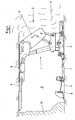
- FIG. 1 A used in underground mining and tunneling hydraulic ram 1 is in FIG. 1 played. It is part of the hydraulic expansion 2, here a shield construction, which is used in the strut 3 to support the hanging wall 4 and 5 lying against each other and so to keep the created cavity open.
- the Hangendkappe 6 is also formed in several parts, such as the horizontal sleeper 7, wherein in the horizontal sleeper 7, a push cylinder 9 is housed, over which the longwall conveyor 8 can be moved in the direction of coal blast 10. Behind the shield removal of the break falls 11 and closes the cavity created again, the breaker plate 12 is employed and supported so that both during the extended hydraulic ram 1 as well as the retracted hydraulic ram 1 always enough security in the longwall 3 is guaranteed.
- FIG. 2 shows a longitudinal section through the hydraulic ram 1, wherein the outer tube is denoted by 15 and the inner tube 19.
- the outer tube 15 with theticianan gleichteil 16 rests in the horizontal sleeper 7, not shown here, while the handle 17 forms the upper end portion of the outer tube 15.
- the actual handle can be dispensed with
- corresponding ring 18 is absolutely necessary, which simultaneously represents a insertion limit for the inner tube 19.
- annular space 14 Between outer tube 15 and inner tube 19 remains an annular space 14, which is needed to support the insertion of the inner tube 19. Further details will be explained later.
- the inner tube 19 is open at the tube end 74 with respect to the outer tube 15, so that when filling hydraulic fluid via the filling / predamper valve 21 or the switching device 24 into the cylinder chamber 80, the inner tube 19 is pushed out of the outer tube 15. This is at the im FIG. 1 shown expansion the hanging end cap 6 pressed against the hanging wall 4. In the process, the corresponding pressure then builds up in the cylinder space 80, which in the embodiment shown here can be built up to a set pressure of up to approximately 600 t.
- the cylinder chamber 80 is closed at the top by the top plate 20, which is fixed to the pipe end 73 of the inner tube 19. Further explanations will be given below.
- the filling and also relieving takes place via the switching device 24, in which case additionally a pressure limiting valve 22 with a flow regulator 26 is provided. If, due to an overload in the cylinder chamber 80, the pressure there is too high, this pressure relief valve 22 opens without the vibrations possibly occurring through the connecting pipe 28 being able to have a disadvantageous effect. This prevents the described flow regulator 26.
- the switching device 24 and the pressure relief valve 22 are connected via a connecting pipe 28 with the cylinder chamber 80, said connecting pipe 28 via brackets 27, 27 'is easy and safe to connect.
- a safety pressure relief valve 23 is shown, which is not absolutely necessary, but can be used for safety reasons. Both this safety pressure limiting valve 23 and the housing 65 of the switching device 24 are fixed via a detachable clamp 25 on the outer tube 15.
- the cylinder chamber 80 is filled with hydraulic fluid. If the inner tube 19 is then retracted later, so the hydraulic ram 1 are relieved, this movement is supported by pressurizing the Einschubbevanteran gleiches 33 with hydraulic fluid. The pressure fluid then acts on the piston 29 of the inner tube 19 and ensures a rapid retraction of the inner tube 19th
- fuse wires 30, 31, 32 are used to connect the items of the hydraulic ram 1 here fuse wires 30, 31, 32 are used. All fuse wires 30, 31, 32 are formed as rectangular spring steel wire anchors 35. They sit in connecting grooves 36, 37, 38 and can be inserted via adjusting screws 48, 49, 50, 51 in the opposite connecting grooves 39, 40, 41, so that they then bridge the transition region 42 and ensure that the corresponding components effectively connected are.
- the fuse wire 30 is seated in the connecting groove 38 and 41.
- the fuse wire 31 is seated in the connecting groove 37 and 40, the fuse wire 32 finally in the connecting groove 36 and 39. Since the corresponding connecting grooves are naturally housed in opposing components, an mecanical truncation 44 for In this way, the various Vietnamesesnute 36 - 41 can be conveniently accommodated, with details in particular the Figures 3 . 4 and 5 can be removed.
- a clamping piston 78 is housed in the region of the top plate 20, which is movable or displaceable with its clamping piston rod 79 in the piston rod 77.
- the clamping piston rod 79 is thereby pushed into the cylinder space 80, so as to increase the pressure.
- 81 designates the tensioning piston connection, via which pressure fluid can thus be forced into the area above the tensioning piston 78.
- FIG. 3 shows an enlarged view of the footrest used in the sleepers 7 foot connector 16.
- the fuse wire 30 is brought into a position that can extend it in part into the connecting groove 40 and the connecting groove 38. It thus bridges the transition region 42 and ensures that here the Robinsonrohrum charged 45 is effectively connected to the outer tube 15.
- 34 test ports are designated here, via which the pressure conditions in the cylinder chamber 80 can be checked and monitored.
- a Teflon ring 75 is shown, which rests in a wide groove 76. This wide Teflon ring 75 ensures that no friction losses occur.
- An identically formed Teflon ring is also reproduced at the pipe end 73 and also designated there by 75.
- a sealing ring 70 is arranged above this Teflon ring 75 in the Breitnut 76, which is fixed on both sides by a support ring 71, 71 '.
- FIG. 4 is a sectional view showing both the diagnosedrohrum charged 46 as the outer tube 15 and the inner tube 19. Fixed or connected here are the outer tube 15 and the mecanicrohrum charged 46 of the handle 17.
- the two components interconnecting fuse wire 31 has been here from the fuse wire 31 receiving groove 37 partially pushed into the groove 40 and that via the screws 48, 49, 50 and 51. These screws 48 - 51 influence the fuse wire 31 evenly, it is expedient to start with the adjusting screw 48. Finally, then the tightened set screws 49, 50 rotated from its outer position into the fixing position, where they then fix the fuse wire ends 53, 54.
- FIG. 5 shows left the starting position of the spring steel wire anchor 35, wherein the adjusting screw 48 or 49 or 50 or 51 is in a position which ensures that the fuse wire 30, 31, 32 and the spring steel wire anchor 35 when inserting, for example, the outer tube 15 in the handle 17th no obstacle.
- the screw 48, 49, 50, 51 via the Imbus 57 at the opposite end of the support surface 55 from the connecting groove 37 in pushed in the connecting groove 40 in such a way that it then completely fills them, but in the transition region 42 always protrudes into the remaining opening of the connecting groove 37. In this way, both components are effectively interconnected.
- the support surface 55 is slightly bent outwardly toward the spring steel wire anchor 35 and the edges 58 of the spring steel wire anchor 35 are slightly rounded so as to facilitate and secure insertion into the connection groove 40.
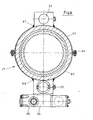
- FIG. 6 Finally, the connection of the switching device 24 and the pressure relief valves 22, 23 with the outer tube 15. To the particular through the connecting pipes 28 to make any possible vibrations on this determination on the outer tube 15 harmless, these components are connected via a releasable clamp 25 together. It also supports the use of non-weldable high-strength pipes.
- This detachable clamp 25 consists of two half-shells 62, 63, which are to be connected by screws 64 together.
- the housing 65 or the pressure relief valve 22, 23 are defined by welds 66, 67 on this releasable clamp 25, so that occurring movements and the like can not affect the connection with the outer tube 15.
Landscapes
- Engineering & Computer Science (AREA)
- Mining & Mineral Resources (AREA)
- Mechanical Engineering (AREA)
- Structural Engineering (AREA)
- Life Sciences & Earth Sciences (AREA)
- General Life Sciences & Earth Sciences (AREA)
- Geochemistry & Mineralogy (AREA)
- Geology (AREA)
- Actuator (AREA)
- Excavating Of Shafts Or Tunnels (AREA)
- Package Frames And Binding Bands (AREA)
- Materials For Medical Uses (AREA)
- Reinforcement Elements For Buildings (AREA)
- Load-Engaging Elements For Cranes (AREA)
- Pit Excavations, Shoring, Fill Or Stabilisation Of Slopes (AREA)
- Soil Working Implements (AREA)
- Supports For Pipes And Cables (AREA)
Claims (15)
- Etançon hydraulique pour utilisation dans l'exploitation minière ou la construction de tunnels souterrains avec un tube extérieur (15) avec pièce de raccordement de pied (16) au bout ainsi qu'une poignée (17) installée à l'extrémité de tube opposée et un tube intérieur (19), décalable dans le tube extérieur (15), avec plaque supérieure (20) au bout ainsi qu'une soupape de remplissage/d'arrachement (21) correspondante, une soupape de limitation de pression (22) et des fils de sûreté (30) à faire glisser dans des rainures de jonction (36) pour le tube extérieur (15), la pièce de raccordement de pied (16) et la poignée (17) ainsi que le tube intérieur (19) et la plaque supérieure (20),
caractérisé en ce que
les fils de sûreté (30, 31, 32) sont formés comme induits à fils (35) rectangulaires, de préférence en acier à ressorts, qui peuvent être logés dans une rainure de jonction (36, 37, 38) correspondant en largeur aux induits à fils en acier à ressorts (35) et peuvent être décalés depuis cette dernière dans la zone de transition (42) et, ainsi, dans la rainure de jonction (39, 40, 41) opposée qui correspond en largeur, rainure dans laquelle ils relient l'une à l'autre les pièces du tube. - Etançon hydraulique selon la revendication 1,
caractérisé en ce que
la rainure de jonction (36, 37, 38) qui loge le fil de sûreté (30, 31, 32) est formée dans la plaque supérieure (20) ou dans la poignée (17) et la pièce de raccordement de pied (16) et la rainure de jonction (39, 40, 41) formée en face est affectée au tube extérieur (15) ou au tube intérieur (19). - Etançon hydraulique selon l'une quelconque des revendications précédentes,
caractérisé en ce que
la rainure de jonction (36, 37, 38) qui loge le fil de sûreté (30, 31, 32) présente une profondeur qui accueille entièrement le fil de sûreté (30, 31, 32), tandis que la rainure de jonction opposée (39, 40, 41) est réalisée avec une profondeur correspondant à environ 50 % l'épaisseur du fil de sûreté. - Etançon hydraulique selon l'une quelconque des revendications précédentes,
caractérisé en ce que
des vis de réglage (48, 49, 50, 51) qui agissent sur le fil de sûreté concerné (30, 31, 32) sont disposées sur la circonférence de l'enceinte du tube intérieur (44) de la plaque supérieure (20) et de l'enceinte du tube extérieur (45, 46) de la pièce de raccordement de pied (16) ou de la poignée (17). - Etançon hydraulique selon la revendication 4,
caractérisé en ce que
l'écartement des vis de réglage (49, 50) aux bouts des fils de sûreté (53, 54) est réduit, de préférence réduit de moitié. - Etançon hydraulique selon la revendication 4,
caractérisé en ce que
les vis de réglage (48, 49, 50, 51) présentent un imbus (57) au bout (56) opposé à la surface d'appui (55). - Etançon hydraulique selon la revendication 6,
caractérisé en ce que
la surface d'appui (55) des vis de réglage (48, 51) est légèrement convexe. - Etançon hydraulique selon l'une quelconque des revendications précédentes,
caractérisé en ce que
les fils de sûreté (30, 31, 32) présentent des arêtes arrondies (58). - Etançon hydraulique selon l'une quelconque des revendications précédentes,
caractérisé en ce que
les fils de sûreté (30, 31, 32) présentent une stabilité d'au moins 100 kg et, à une hauteur de 5 - 7 mm, de préférence une hauteur de 6 mm, une largeur de 15 - 20 mm, de préférence 17 mm. - Etançon hydraulique selon l'une quelconque des revendications précédentes,
caractérisé en ce que
est affecté à la plaque supérieure (20) un soi-disant « packer » (60) se composant d'un piston de serrage (78) disposé de manière décalable dans la tige de piston (77) avec tige de piston de serrage (79) que l'on peut faire glisser dans le compartiment de cylindre (80), étant donné que le liquide sous pression dans le compartiment de cylindre (80) peut encore une fois, en complément, être fortement comprimé au moyen du piston de serrage (78). - Etançon hydraulique selon la revendication 1,
caractérisé en ce que
un équipement de commutation (24) avec soupape de limitation de pression (22) est affecté au tube extérieur (15) par l'intermédiaire d'un collier (25) amovible. - Etançon hydraulique selon la revendication 11,
caractérisé en ce que
le collier (25) présente deux demi-coques (62, 63) pouvant être reliées l'une à l'autre au moyen de vis (64), demi-coques sur lesquelles est soudé le boîtier (65) de l'équipement de commutation (24) et, le cas échéant, d'une deuxième soupape de limitation de pression (23) prévue à titre de sécurité. - Etançon hydraulique selon la revendication 11,
caractérisé en ce que
la soupape de limitation de pression (22) affectée à l'équipement de commutation (24) dispose côté entrée d'un régulateur de flux (26). - Etançon hydraulique selon l'une quelconque des revendications précédentes,
caractérisé en ce que
des bagues d'appui (71) supplémentaires en métal sont disposées dans les rainures (69) dans lesquelles sont disposées les joints d'étanchéité (70) affectés aux fils de sûreté (30, 31, 32). - Etançon hydraulique selon l'une quelconque des revendications précédentes,
caractérisé en ce que
une large bague en Teflon (75) disposée dans une large rainure (76) est affectée aux deux bouts (73, 74) du tube intérieur (19).
Priority Applications (1)
| Application Number | Priority Date | Filing Date | Title |
|---|---|---|---|
| PL08734477T PL2147191T3 (pl) | 2007-04-17 | 2008-04-09 | Stojak hydrauliczny z prostokątnymi drutami zabezpieczającymi |
Applications Claiming Priority (2)
| Application Number | Priority Date | Filing Date | Title |
|---|---|---|---|
| DE102007018021A DE102007018021A1 (de) | 2007-04-17 | 2007-04-17 | Hydraulikstempel mit dünnwandigen Außen- und Innenrohren |
| PCT/DE2008/000598 WO2008125082A2 (fr) | 2007-04-17 | 2008-04-09 | Vérin hydraulique présentant des tubes extérieurs et intérieurs à parois minces |
Publications (2)
| Publication Number | Publication Date |
|---|---|
| EP2147191A2 EP2147191A2 (fr) | 2010-01-27 |
| EP2147191B1 true EP2147191B1 (fr) | 2010-07-14 |
Family
ID=39767791
Family Applications (1)
| Application Number | Title | Priority Date | Filing Date |
|---|---|---|---|
| EP08734477A Not-in-force EP2147191B1 (fr) | 2007-04-17 | 2008-04-09 | Vérin hydraulique présentant des fils de securité à section rectangulaire |
Country Status (7)
| Country | Link |
|---|---|
| US (1) | US8297888B2 (fr) |
| EP (1) | EP2147191B1 (fr) |
| AT (1) | ATE474126T1 (fr) |
| AU (1) | AU2008238408B2 (fr) |
| DE (2) | DE102007018021A1 (fr) |
| PL (1) | PL2147191T3 (fr) |
| WO (1) | WO2008125082A2 (fr) |
Families Citing this family (8)
| Publication number | Priority date | Publication date | Assignee | Title |
|---|---|---|---|---|
| CN101944299B (zh) * | 2010-07-30 | 2011-11-02 | 巩亚东 | 全断面掘进机虚拟施工系统 |
| CN102477867A (zh) * | 2010-11-23 | 2012-05-30 | 杨传蔚 | 一种新型单体液压支柱 |
| CN102536289B (zh) * | 2012-03-07 | 2014-04-02 | 中煤北京煤矿机械有限责任公司 | 中厚煤层两柱掩护式大中心距超高工作阻力液压支架 |
| US8985699B2 (en) * | 2013-03-14 | 2015-03-24 | Seneca Industries Inc. | Mining methods and equipment |
| CN103244152A (zh) * | 2013-05-15 | 2013-08-14 | 淮南郑煤机舜立机械有限公司 | 液压支柱 |
| CN106593496B (zh) * | 2016-12-09 | 2018-12-07 | 太原科技大学 | 填充式空心液压支柱装置 |
| CN106934251B (zh) * | 2017-04-25 | 2019-04-16 | 浙江大学城市学院 | 一种类矩形盾构隧道施工中地表沉降计算方法 |
| CN113039345A (zh) | 2018-09-24 | 2021-06-25 | 久益环球地下采矿有限责任公司 | 包括可延伸的连杆的顶板支架 |
Family Cites Families (6)
| Publication number | Priority date | Publication date | Assignee | Title |
|---|---|---|---|---|
| US2719688A (en) * | 1949-11-21 | 1955-10-04 | Seifert Karl | Telescopic tubes |
| DE1943419U (de) * | 1965-07-13 | 1966-08-04 | Hoesch Bergbautechnik G M B H | Hydraulischer grubenstempel mit doppelter ausziehbarkeit und zwei getrennten druckraeumen. |
| DE2921901C2 (de) * | 1979-05-30 | 1986-03-20 | Felix 6680 Neunkirchen Ecker | In eine Druckwasserleitung einsetzbarer Filter |
| DE10229303A1 (de) | 2002-04-03 | 2003-10-16 | Vos Richard Grubenausbau Gmbh | Hydraulikstempel mit vereinzelt im Stempelkopf untergebrachten Ventilen |
| DE10306128A1 (de) | 2003-02-14 | 2004-08-26 | Richard Voß Grubenausbau GmbH | Verfahren und Vorrichtung zur Druckerhöhung in Zylindern, insbesondere hydraulischen Stempeln |
| CN100535394C (zh) * | 2005-10-31 | 2009-09-02 | 中国矿业大学 | 悬浮式液压支柱 |
-
2007
- 2007-04-17 DE DE102007018021A patent/DE102007018021A1/de not_active Withdrawn
-
2008
- 2008-04-09 WO PCT/DE2008/000598 patent/WO2008125082A2/fr active Application Filing
- 2008-04-09 AT AT08734477T patent/ATE474126T1/de active
- 2008-04-09 US US12/450,901 patent/US8297888B2/en not_active Expired - Fee Related
- 2008-04-09 AU AU2008238408A patent/AU2008238408B2/en not_active Ceased
- 2008-04-09 EP EP08734477A patent/EP2147191B1/fr not_active Not-in-force
- 2008-04-09 DE DE502008000961T patent/DE502008000961D1/de active Active
- 2008-04-09 PL PL08734477T patent/PL2147191T3/pl unknown
Also Published As
| Publication number | Publication date |
|---|---|
| DE102007018021A1 (de) | 2008-10-23 |
| WO2008125082A2 (fr) | 2008-10-23 |
| DE502008000961D1 (de) | 2010-08-26 |
| WO2008125082A3 (fr) | 2009-02-05 |
| US8297888B2 (en) | 2012-10-30 |
| ATE474126T1 (de) | 2010-07-15 |
| EP2147191A2 (fr) | 2010-01-27 |
| AU2008238408A1 (en) | 2008-10-23 |
| PL2147191T3 (pl) | 2010-12-31 |
| AU2008238408B2 (en) | 2013-08-01 |
| US20100119311A1 (en) | 2010-05-13 |
Similar Documents
| Publication | Publication Date | Title |
|---|---|---|
| EP2147191B1 (fr) | Vérin hydraulique présentant des fils de securité à section rectangulaire | |
| DE2517613C3 (de) | Bohrlochwerkzeug sowie Verfahren zum Befestigen und Lösen eines Bohrlochwerkzeugs auf bzw. von einem Bohrgestänge | |
| EP0808436B1 (fr) | Procede d'extraction d'un objet creux enterre | |
| EP0817936B1 (fr) | Procede et dispositif de traction d'un tuyau pose ou a poser dans le sol | |
| DE3415627A1 (de) | Rohrpruefgeraet | |
| DE4127249C1 (fr) | ||
| DE2437199A1 (de) | Verfahren und vorrichtung zum verbinden der enden von bewehrungsstaeben | |
| EP2527589A2 (fr) | Ancre pour la roche | |
| EP2674569A1 (fr) | Garniture de joint pour avancées tubulaires | |
| DE10057041A1 (de) | Gebirgsanker mit aufweitbarem Ankerinnenrohr | |
| DE3301262A1 (de) | Mechanisiertes ausbauelement fuer den grubenbetrieb | |
| DE4401480A1 (de) | Ausbaustempel mit integrierter Ventilhülse für ein Druckbegrenzungsventil | |
| DE3025236A1 (de) | Wanderndes oder verfahrbares stuetzgeruest | |
| WO2011069480A2 (fr) | Cuvelage à élément élastique intégré | |
| DE102006006093B3 (de) | Spannvorrichtung zum Spannen eines Werkstücks | |
| DE10332328B3 (de) | Vorrichtung zum Erneuern von im Erdreich verlegten Versorgungsleitungen | |
| WO2011069482A2 (fr) | Soutènement souterrain à accouplement élastique | |
| CH704231A2 (de) | Rohrleitung mit mindestens zwei Rohrelementen und einem zwischen den Stirnseiten der Rohrelemente befindlichen Schlauch als Druckübertragungsmittel und Dichtung. | |
| DE4441778C2 (de) | Ausbaustempel mit einem Druckflüssigkeitsfilm zwischen der Außenwand des Kolbens und der Innenwand des Außenstempels | |
| DE102008011907A1 (de) | Rohrbefestiger | |
| DE202004009239U1 (de) | Hydraulischer Einzel- oder Doppelhubstempel mit Reparatursicherheiten | |
| DE1902042A1 (de) | Wandernder Strebausbau fuer untertaegige Grubenbetriebe | |
| DE2038170C (de) | Vorrichtung zum Verankern relativ weicher Gesteins- und Mineralschichten | |
| AT393537B (de) | Bohrgeraet | |
| DE2313664C3 (de) | Schwerstangen |
Legal Events
| Date | Code | Title | Description |
|---|---|---|---|
| PUAI | Public reference made under article 153(3) epc to a published international application that has entered the european phase |
Free format text: ORIGINAL CODE: 0009012 |
|
| 17P | Request for examination filed |
Effective date: 20091117 |
|
| AK | Designated contracting states |
Kind code of ref document: A2 Designated state(s): AT BE BG CH CY CZ DE DK EE ES FI FR GB GR HR HU IE IS IT LI LT LU LV MC MT NL NO PL PT RO SE SI SK TR |
|
| AX | Request for extension of the european patent |
Extension state: AL BA MK RS |
|
| GRAP | Despatch of communication of intention to grant a patent |
Free format text: ORIGINAL CODE: EPIDOSNIGR1 |
|
| RTI1 | Title (correction) |
Free format text: HYDRAULIC RAM COMPRISING SQUARE-SECTION LOCKING WIRES |
|
| GRAS | Grant fee paid |
Free format text: ORIGINAL CODE: EPIDOSNIGR3 |
|
| GRAA | (expected) grant |
Free format text: ORIGINAL CODE: 0009210 |
|
| AK | Designated contracting states |
Kind code of ref document: B1 Designated state(s): AT BE BG CH CY CZ DE DK EE ES FI FR GB GR HR HU IE IS IT LI LT LU LV MC MT NL NO PL PT RO SE SI SK TR |
|
| REG | Reference to a national code |
Ref country code: GB Ref legal event code: FG4D Free format text: NOT ENGLISH |
|
| REG | Reference to a national code |
Ref country code: CH Ref legal event code: EP |
|
| REG | Reference to a national code |
Ref country code: IE Ref legal event code: FG4D |
|
| REF | Corresponds to: |
Ref document number: 502008000961 Country of ref document: DE Date of ref document: 20100826 Kind code of ref document: P |
|
| REG | Reference to a national code |
Ref country code: NL Ref legal event code: VDEP Effective date: 20100714 |
|
| LTIE | Lt: invalidation of european patent or patent extension |
Effective date: 20100714 |
|
| REG | Reference to a national code |
Ref country code: PL Ref legal event code: T3 |
|
| PG25 | Lapsed in a contracting state [announced via postgrant information from national office to epo] |
Ref country code: LT Free format text: LAPSE BECAUSE OF FAILURE TO SUBMIT A TRANSLATION OF THE DESCRIPTION OR TO PAY THE FEE WITHIN THE PRESCRIBED TIME-LIMIT Effective date: 20100714 Ref country code: FI Free format text: LAPSE BECAUSE OF FAILURE TO SUBMIT A TRANSLATION OF THE DESCRIPTION OR TO PAY THE FEE WITHIN THE PRESCRIBED TIME-LIMIT Effective date: 20100714 Ref country code: NL Free format text: LAPSE BECAUSE OF FAILURE TO SUBMIT A TRANSLATION OF THE DESCRIPTION OR TO PAY THE FEE WITHIN THE PRESCRIBED TIME-LIMIT Effective date: 20100714 Ref country code: NO Free format text: LAPSE BECAUSE OF FAILURE TO SUBMIT A TRANSLATION OF THE DESCRIPTION OR TO PAY THE FEE WITHIN THE PRESCRIBED TIME-LIMIT Effective date: 20101014 |
|
| REG | Reference to a national code |
Ref country code: IE Ref legal event code: FD4D |
|
| PG25 | Lapsed in a contracting state [announced via postgrant information from national office to epo] |
Ref country code: BG Free format text: LAPSE BECAUSE OF FAILURE TO SUBMIT A TRANSLATION OF THE DESCRIPTION OR TO PAY THE FEE WITHIN THE PRESCRIBED TIME-LIMIT Effective date: 20101014 Ref country code: SI Free format text: LAPSE BECAUSE OF FAILURE TO SUBMIT A TRANSLATION OF THE DESCRIPTION OR TO PAY THE FEE WITHIN THE PRESCRIBED TIME-LIMIT Effective date: 20100714 Ref country code: IS Free format text: LAPSE BECAUSE OF FAILURE TO SUBMIT A TRANSLATION OF THE DESCRIPTION OR TO PAY THE FEE WITHIN THE PRESCRIBED TIME-LIMIT Effective date: 20101114 Ref country code: HR Free format text: LAPSE BECAUSE OF FAILURE TO SUBMIT A TRANSLATION OF THE DESCRIPTION OR TO PAY THE FEE WITHIN THE PRESCRIBED TIME-LIMIT Effective date: 20100714 Ref country code: CY Free format text: LAPSE BECAUSE OF FAILURE TO SUBMIT A TRANSLATION OF THE DESCRIPTION OR TO PAY THE FEE WITHIN THE PRESCRIBED TIME-LIMIT Effective date: 20100714 |
|
| PG25 | Lapsed in a contracting state [announced via postgrant information from national office to epo] |
Ref country code: GR Free format text: LAPSE BECAUSE OF FAILURE TO SUBMIT A TRANSLATION OF THE DESCRIPTION OR TO PAY THE FEE WITHIN THE PRESCRIBED TIME-LIMIT Effective date: 20101015 Ref country code: LV Free format text: LAPSE BECAUSE OF FAILURE TO SUBMIT A TRANSLATION OF THE DESCRIPTION OR TO PAY THE FEE WITHIN THE PRESCRIBED TIME-LIMIT Effective date: 20100714 Ref country code: SE Free format text: LAPSE BECAUSE OF FAILURE TO SUBMIT A TRANSLATION OF THE DESCRIPTION OR TO PAY THE FEE WITHIN THE PRESCRIBED TIME-LIMIT Effective date: 20100714 |
|
| PG25 | Lapsed in a contracting state [announced via postgrant information from national office to epo] |
Ref country code: IE Free format text: LAPSE BECAUSE OF FAILURE TO SUBMIT A TRANSLATION OF THE DESCRIPTION OR TO PAY THE FEE WITHIN THE PRESCRIBED TIME-LIMIT Effective date: 20100714 Ref country code: DK Free format text: LAPSE BECAUSE OF FAILURE TO SUBMIT A TRANSLATION OF THE DESCRIPTION OR TO PAY THE FEE WITHIN THE PRESCRIBED TIME-LIMIT Effective date: 20100714 |
|
| PLBE | No opposition filed within time limit |
Free format text: ORIGINAL CODE: 0009261 |
|
| STAA | Information on the status of an ep patent application or granted ep patent |
Free format text: STATUS: NO OPPOSITION FILED WITHIN TIME LIMIT |
|
| PG25 | Lapsed in a contracting state [announced via postgrant information from national office to epo] |
Ref country code: SK Free format text: LAPSE BECAUSE OF FAILURE TO SUBMIT A TRANSLATION OF THE DESCRIPTION OR TO PAY THE FEE WITHIN THE PRESCRIBED TIME-LIMIT Effective date: 20100714 Ref country code: IT Free format text: LAPSE BECAUSE OF FAILURE TO SUBMIT A TRANSLATION OF THE DESCRIPTION OR TO PAY THE FEE WITHIN THE PRESCRIBED TIME-LIMIT Effective date: 20100714 Ref country code: CZ Free format text: LAPSE BECAUSE OF FAILURE TO SUBMIT A TRANSLATION OF THE DESCRIPTION OR TO PAY THE FEE WITHIN THE PRESCRIBED TIME-LIMIT Effective date: 20100714 Ref country code: RO Free format text: LAPSE BECAUSE OF FAILURE TO SUBMIT A TRANSLATION OF THE DESCRIPTION OR TO PAY THE FEE WITHIN THE PRESCRIBED TIME-LIMIT Effective date: 20100714 Ref country code: EE Free format text: LAPSE BECAUSE OF FAILURE TO SUBMIT A TRANSLATION OF THE DESCRIPTION OR TO PAY THE FEE WITHIN THE PRESCRIBED TIME-LIMIT Effective date: 20100714 |
|
| 26N | No opposition filed |
Effective date: 20110415 |
|
| PG25 | Lapsed in a contracting state [announced via postgrant information from national office to epo] |
Ref country code: ES Free format text: LAPSE BECAUSE OF FAILURE TO SUBMIT A TRANSLATION OF THE DESCRIPTION OR TO PAY THE FEE WITHIN THE PRESCRIBED TIME-LIMIT Effective date: 20101025 |
|
| REG | Reference to a national code |
Ref country code: DE Ref legal event code: R097 Ref document number: 502008000961 Country of ref document: DE Effective date: 20110415 |
|
| BERE | Be: lapsed |
Owner name: VOSS, WOLFGANG Effective date: 20110430 |
|
| PG25 | Lapsed in a contracting state [announced via postgrant information from national office to epo] |
Ref country code: MC Free format text: LAPSE BECAUSE OF NON-PAYMENT OF DUE FEES Effective date: 20110430 |
|
| PG25 | Lapsed in a contracting state [announced via postgrant information from national office to epo] |
Ref country code: MT Free format text: LAPSE BECAUSE OF FAILURE TO SUBMIT A TRANSLATION OF THE DESCRIPTION OR TO PAY THE FEE WITHIN THE PRESCRIBED TIME-LIMIT Effective date: 20100714 |
|
| REG | Reference to a national code |
Ref country code: FR Ref legal event code: ST Effective date: 20111230 |
|
| PG25 | Lapsed in a contracting state [announced via postgrant information from national office to epo] |
Ref country code: BE Free format text: LAPSE BECAUSE OF NON-PAYMENT OF DUE FEES Effective date: 20110430 Ref country code: FR Free format text: LAPSE BECAUSE OF NON-PAYMENT OF DUE FEES Effective date: 20110502 |
|
| REG | Reference to a national code |
Ref country code: CH Ref legal event code: PL |
|
| GBPC | Gb: european patent ceased through non-payment of renewal fee |
Effective date: 20120409 |
|
| PG25 | Lapsed in a contracting state [announced via postgrant information from national office to epo] |
Ref country code: LI Free format text: LAPSE BECAUSE OF NON-PAYMENT OF DUE FEES Effective date: 20120430 Ref country code: CH Free format text: LAPSE BECAUSE OF NON-PAYMENT OF DUE FEES Effective date: 20120430 Ref country code: GB Free format text: LAPSE BECAUSE OF NON-PAYMENT OF DUE FEES Effective date: 20120409 |
|
| PG25 | Lapsed in a contracting state [announced via postgrant information from national office to epo] |
Ref country code: LU Free format text: LAPSE BECAUSE OF NON-PAYMENT OF DUE FEES Effective date: 20110409 |
|
| PGFP | Annual fee paid to national office [announced via postgrant information from national office to epo] |
Ref country code: PL Payment date: 20130318 Year of fee payment: 6 |
|
| PG25 | Lapsed in a contracting state [announced via postgrant information from national office to epo] |
Ref country code: PT Free format text: LAPSE BECAUSE OF NON-PAYMENT OF DUE FEES Effective date: 20100714 |
|
| PGFP | Annual fee paid to national office [announced via postgrant information from national office to epo] |
Ref country code: DE Payment date: 20130426 Year of fee payment: 6 |
|
| PG25 | Lapsed in a contracting state [announced via postgrant information from national office to epo] |
Ref country code: TR Free format text: LAPSE BECAUSE OF FAILURE TO SUBMIT A TRANSLATION OF THE DESCRIPTION OR TO PAY THE FEE WITHIN THE PRESCRIBED TIME-LIMIT Effective date: 20100714 |
|
| PG25 | Lapsed in a contracting state [announced via postgrant information from national office to epo] |
Ref country code: HU Free format text: LAPSE BECAUSE OF FAILURE TO SUBMIT A TRANSLATION OF THE DESCRIPTION OR TO PAY THE FEE WITHIN THE PRESCRIBED TIME-LIMIT Effective date: 20100714 |
|
| REG | Reference to a national code |
Ref country code: AT Ref legal event code: MM01 Ref document number: 474126 Country of ref document: AT Kind code of ref document: T Effective date: 20130409 |
|
| PG25 | Lapsed in a contracting state [announced via postgrant information from national office to epo] |
Ref country code: AT Free format text: LAPSE BECAUSE OF NON-PAYMENT OF DUE FEES Effective date: 20130409 |
|
| REG | Reference to a national code |
Ref country code: DE Ref legal event code: R119 Ref document number: 502008000961 Country of ref document: DE |
|
| REG | Reference to a national code |
Ref country code: DE Ref legal event code: R119 Ref document number: 502008000961 Country of ref document: DE Effective date: 20141101 |
|
| PG25 | Lapsed in a contracting state [announced via postgrant information from national office to epo] |
Ref country code: DE Free format text: LAPSE BECAUSE OF NON-PAYMENT OF DUE FEES Effective date: 20141101 |
|
| REG | Reference to a national code |
Ref country code: PL Ref legal event code: LAPE |
|
| PG25 | Lapsed in a contracting state [announced via postgrant information from national office to epo] |
Ref country code: PL Free format text: LAPSE BECAUSE OF NON-PAYMENT OF DUE FEES Effective date: 20140409 |