EP2144154A2 - Appareil de commande d'impression, procédé de commande d'impression et son programme - Google Patents
Appareil de commande d'impression, procédé de commande d'impression et son programme Download PDFInfo
- Publication number
- EP2144154A2 EP2144154A2 EP09165207A EP09165207A EP2144154A2 EP 2144154 A2 EP2144154 A2 EP 2144154A2 EP 09165207 A EP09165207 A EP 09165207A EP 09165207 A EP09165207 A EP 09165207A EP 2144154 A2 EP2144154 A2 EP 2144154A2
- Authority
- EP
- European Patent Office
- Prior art keywords
- page
- toner
- printing
- clear
- pages
- Prior art date
- Legal status (The legal status is an assumption and is not a legal conclusion. Google has not performed a legal analysis and makes no representation as to the accuracy of the status listed.)
- Withdrawn
Links
Images


Classifications
-
- G—PHYSICS
- G06—COMPUTING; CALCULATING OR COUNTING
- G06F—ELECTRIC DIGITAL DATA PROCESSING
- G06F3/00—Input arrangements for transferring data to be processed into a form capable of being handled by the computer; Output arrangements for transferring data from processing unit to output unit, e.g. interface arrangements
- G06F3/12—Digital output to print unit, e.g. line printer, chain printer
- G06F3/1201—Dedicated interfaces to print systems
- G06F3/1223—Dedicated interfaces to print systems specifically adapted to use a particular technique
- G06F3/1237—Print job management
- G06F3/125—Page layout or assigning input pages onto output media, e.g. imposition
-
- G—PHYSICS
- G06—COMPUTING; CALCULATING OR COUNTING
- G06F—ELECTRIC DIGITAL DATA PROCESSING
- G06F3/00—Input arrangements for transferring data to be processed into a form capable of being handled by the computer; Output arrangements for transferring data from processing unit to output unit, e.g. interface arrangements
- G06F3/12—Digital output to print unit, e.g. line printer, chain printer
- G06F3/1201—Dedicated interfaces to print systems
- G06F3/1202—Dedicated interfaces to print systems specifically adapted to achieve a particular effect
- G06F3/1203—Improving or facilitating administration, e.g. print management
- G06F3/1204—Improving or facilitating administration, e.g. print management resulting in reduced user or operator actions, e.g. presetting, automatic actions, using hardware token storing data
-
- G—PHYSICS
- G06—COMPUTING; CALCULATING OR COUNTING
- G06F—ELECTRIC DIGITAL DATA PROCESSING
- G06F3/00—Input arrangements for transferring data to be processed into a form capable of being handled by the computer; Output arrangements for transferring data from processing unit to output unit, e.g. interface arrangements
- G06F3/12—Digital output to print unit, e.g. line printer, chain printer
- G06F3/1201—Dedicated interfaces to print systems
- G06F3/1202—Dedicated interfaces to print systems specifically adapted to achieve a particular effect
- G06F3/1203—Improving or facilitating administration, e.g. print management
- G06F3/1208—Improving or facilitating administration, e.g. print management resulting in improved quality of the output result, e.g. print layout, colours, workflows, print preview
-
- G—PHYSICS
- G06—COMPUTING; CALCULATING OR COUNTING
- G06F—ELECTRIC DIGITAL DATA PROCESSING
- G06F3/00—Input arrangements for transferring data to be processed into a form capable of being handled by the computer; Output arrangements for transferring data from processing unit to output unit, e.g. interface arrangements
- G06F3/12—Digital output to print unit, e.g. line printer, chain printer
- G06F3/1201—Dedicated interfaces to print systems
- G06F3/1223—Dedicated interfaces to print systems specifically adapted to use a particular technique
- G06F3/1237—Print job management
- G06F3/1253—Configuration of print job parameters, e.g. using UI at the client
-
- G—PHYSICS
- G06—COMPUTING; CALCULATING OR COUNTING
- G06F—ELECTRIC DIGITAL DATA PROCESSING
- G06F3/00—Input arrangements for transferring data to be processed into a form capable of being handled by the computer; Output arrangements for transferring data from processing unit to output unit, e.g. interface arrangements
- G06F3/12—Digital output to print unit, e.g. line printer, chain printer
- G06F3/1201—Dedicated interfaces to print systems
- G06F3/1278—Dedicated interfaces to print systems specifically adapted to adopt a particular infrastructure
- G06F3/1285—Remote printer device, e.g. being remote from client or server
-
- G—PHYSICS
- G06—COMPUTING; CALCULATING OR COUNTING
- G06F—ELECTRIC DIGITAL DATA PROCESSING
- G06F9/00—Arrangements for program control, e.g. control units
Definitions
- An allover coating using the clear toner prints a clear toner on one face of a sheet following performing color printing, thereby providing a glossy feel as to the sheet overall as with a photograph. Also, a partial coat using clear toner prints clear toner printing partially on to a sheet following performing color printing, thereby providing wide uses such as partial gloss or partial decoration.
- the present invention in its third aspect provides a method for a printing control apparatus as specified in claim 14.
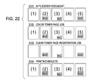
- Fig. 22 is a diagram schematically illustrating the application document, a color toner page job which the printer driver issues as to the printer, a clear toner page registration job which the printer driver generates, and the page output of the printing results.
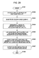
- Fig. 26 is a flowchart describing processing for the printer driver to automatically generate a clear toner page from a color toner page according to a fourth embodiment of the present invention.
- the graphics engine 201 similarly loads the printer driver 202 prepared for the printer 150 from the external memory 111 in the RAM 102, and sets the output of the application 200 to the printer driver 202.
- the graphics engine 201 converts a GDI function received from the application into a DDI function, and outputs the DDI function to the printer driver 202.
- GDI refers to a Graphic Device Interface
- DDI refers to a Device Driver Interface
- a graphics engine is equivalent to a drawing unit of an OS called GDI with Windows® OS.
- the printer driver 202 performs conversion into control commands recognizable by the printer, based on the DDI function received from the graphics engine 201, e.g. into PDL (Page Description Language).
- the converted printer control command is arranged so as to be output as printing data to the printer 150, via the interface 130, by way of the system spooler 203 loaded in the RAM 102 with the OS.
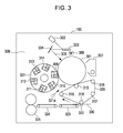
- Fig. 3 is a cross-sectional diagram of the color laser printer showing an example of the printer 150.
- the printer 150 has a drum-shaped electronic photosensitive device serving as an image bearing member, i.e. a photosensitive drum 301.
- a charger 306 serving as a charging device
- a laser light source 302 serving as an exposure device
- a polygon mirror 303 and mirror 304 to reflect the light image 305 that is irradiated from the laser light source.
- a cleaner 307 serving as a cleaning device and a rotational developing device 308 are also disposed in the periphery of the photosensitive drum 301. Also, facing the photosensitive drum 301, an intermediate transfer belt 320 is disposed as an intermediate transfer unit serving as a second image bearing member that is supported by rollers 316, 317, 318, and 319.
- the rotational developing device 308 is disposed so as to face the photosensitive drum 301, and has a rotating member that is rotatably supported, i.e. a developing rotary 321.
- a developing rotary 321 color toner developing devices for four colors and a special color toner developing device for one color are mounted as multiple developing devices.
- the color toner developing devices for four colors are a yellow toner developing device 309, magenta toner developing device 310, cyan toner developing device 311, black toner developing device 312, and light black toner developing device 313.
- the special color toner developing device for one color is a transparent toner (clear toner) developing device 314 for a special color toner for adjusting glossiness.
- the surface thereof is charged with the charger 306.
- a light image 305 is irradiated from the laser light source 302 to the surface of the charged photosensitive drum 301.
- the multi-layered toner image formed on the intermediate transfer belt 320 is transferred to a recording member 330 with the actions of a secondary transfer bias applied to a secondary transfer roller 322, with a facing portion (secondary transfer unit) with the secondary transfer roller 322 serving as the secondary transfer device and the intermediate transfer belt 320.
- the recording member 330 is conveyed from an unshown recording member supply unit to the secondary transfer unit, to match the timing that the leading edge of the multi-layered toner image on the intermediate transfer belt 320 is conveyed to the secondary transfer unit.
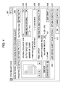
- Fig. 4 is a diagram showing a first layer of the user interface with the printer driver 202.
- 401 is a printing setting dialog box, which can be opened from a printing setting screen or the like of a printer folder or application 200 managed with the OS (can be instructed to display).
- the CPU 101 detecting such display instructions executes the printer driver 202 loaded on the RAM 102 to perform control such that the printing setting dialog box 401 is displayed on the CRT 110.
- the arrangement shown in Fig. 4 is a user interface of a page setting sheet 402 which can perform basic printing settings.
- the document size 403 specified with the application and the output sheet size 404 to actually perform printing can be specified.
- the number of copies 412 to be printed, the printing direction 405 such as portrait or landscape, the page layout 406 such as N-up, the enlarge/reduce 407 for freely enlarging/reducing, and the edit stamp 408 for setting the details about the stamp function can be specified.
- a user defined sheet can also be created with the user defined sheet button 409.
- various types of options performed with the printer driver 202 such as page design, overlay, and so forth, can be set by pressing the page options button 410.
- a return to default button 411 is a button used to return the above-mentioned settings to a default state.
- the printer driver 202 generates PDL data based on content specified from the content set in the main user interface 401 and application at the time of printing execution, and sends this to the printer 150.
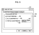
- Fig. 5 is a diagram illustrating a user interface of a page options dialog box 501 which the printer driver 202 opens (displays on the CRT 110) at the time that the page options button 410 shown in Fig. 4 is pressed by the user.
- a clear toner setting screen 502 to set the clear toner usage method exists.
- the clear toner setting screen 502 will be described below.
- the clear toner setting screen 502 has a "processing method” region 503 that can select the processing method thereof.
- the processing methods are made up of selectable radio buttons of "do not perform” 504, "all clear printing” 505, and "partial clear printing” 506.
- the printer driver 202 performs processing as a normal color job that does not use clear toner. Also, in the event that "all clear printing" 505 is specified, the printer driver 202 instructs the printer 150 to perform so that all clear printing is performed in addition to the normal color job processing.
- the all clear printing here indicates processing to coat the entire sheet of the recording sheet 330 evenly with clear toner, in addition to the color toner printing such as CMYK.
- the instructions as to the printer 150 may be performed with a PDL command, or may be performed by sending another control command to the printer 150.
- the printer driver 202 performs processing to coat only a portion of the sheet 330 with clear toner in comparison to "all clear printing” which coats the entire sheet 330.
- the printer driver 202 controls the "partial clear details" button 507 to further enable specifying of partial clear details.
- Fig. 6 is a diagram illustrating an example of a user interface of a "partial clear details" dialog box 601 (special color toner page setting screen) which the printer driver 202 opens in the event that a "partial clear details" button 507 shown in Fig. 5 is pressed by the user.
- a "partial clear details" dialog box 601 special color toner page setting screen
- the printer driver 202 specifies the pages to print with clear toner out of the page groups specified as one job by the application 200 at region 611.
- the printer driver 202 instructs the printer 150 to perform printing using color toner to print all of the objects drawn on the even-numbered pages, and using clear toner for all of the objects drawn on the odd-numbered pages.
- first half (second half) of pages" 613 which is the second specifying method
- the printer driver 202 instructs the printer 150 to perform printing using color toner such as CMYK for all of the objects drawn on the remaining pages not specified as clear toner dedicated pages.
- the printer driver 202 instructs the printer 150 to perform printing using all clear toner for all of the objects drawn on the pages specified as clear toner dedicated pages.
- a user interface 616 to perform page specifying and a user interface 617 showing which of the first half or second half of the job is specified as clear toner dedicated pages are exemplified in Fig. 6 .
- a user is not necessarily made to perform page specifying.
- the printer driver 202 may automatically calculate the number of pages for switching, such as dividing the number of pages by 2 after all of the pages are printed as one job from the application 200.
- dialog box 701 shown in the later-described Fig. 7 .
- the dialog box 701 is displayed with a printer driver 202 at the time that the "specify pages" button 618 is pressed.
- "specify with different job” 620 we presume that the color toner job and clear toner job are specified with different jobs from the application 200.
- the clear toner job is created with the application 200 beforehand and registered in the printer 150.
- the user creates the color toner job separately with the application 200, and specifies to use the data registered at time of printing.
- a method to instruct the printer 150 of layered printing from the printer driver 202 is similar to a currently existing form overlay function.
- the user interface 621 is a user interface for the user to select whether to register the current job as a "clear toner job" or "use previously registered clear toner job".
- the user interface 621 in the event that "create a clear file” 622 is selected, the user performs registration instructions to the printer 150 with a file name input with "save file name” 624.
- the user performs printing instructions to the printer 150 so as to print the registered file of the file name input with "user file name” 625 with clear toner layered over the current job.
- Detailed operations at the time of specifying with different jobs for the registration of the clear toner job and a job using previously registered clear toner job are not directly related to the embodiments of the present invention so will be omitted.
- printer 150 receiving two types of jobs processes the jobs is content related to embodiments of the present invention so will be described briefly with the description in the later-described Fig. 20 .
- Fig. 7 is a diagram illustrating a user interface which the printer driver 202 opens (displays on the CRT 110) at the time that the "specify pages" button 618 shown in Fig. 6 is pressed.
- the user inputs page numbers to be printed with clear toner in an edit box region 702, separated by commas.
- the page numbers input in an edit box region 702 are displayed in the list box 704, one row at a time, by the printer driver 202.
- the printer driver 202 Upon a "deleted" button 705 being pressed in the state that a row of a displayed page number is selected, the printer driver 202 deletes the selected row within the list box 704.
- a page number N that is input in the dialog box 701 is printed with clear toner layered over the color toner printing of page number N - 1. Therefore, it is desirable for the printer driver 202 to control with the user interface so that input cannot be made as to "page 1" or "continuously-numbered pages". It is desirable for the page previous to the page thus specified to be a color toner page. Note that an arrangement may be made wherein the page number N input in the dialog box 701 is printed with clear toner so as to be layered on the color toner printing of the page number N + 1. In the case of this configuration, it is desirable for the printer driver 202 to control with the user interface so that input cannot be made as to "last page” or “continuously-numbered pages”. Also, it is desirable for the one page following the page thus specified to be a page for color toner.
- Fig. 8 is a diagram illustrating a user interface of a page option dialog box 501 which the printer driver 202 opens (displayed on the CRT 110) at the time that a page option button 410 shown in Fig. 4 is pressed by a user. Note that with Fig. 8 , a setting screen 802 of the page design will be described.
- the printer driver 202 Upon the current page design function being specified, the printer driver 202 adds the drawing objects in the form of adding drawing objects drawn from the application 200. Specifically, upon printing of the page frame, date, user name, and page number being specified with the combo boxes 803, 804, 805, and 806 respectively, the printer driver 202 adds the objects thereof as to the PDL data transmitted to the printer 150 in the event of printing processing.
- Fig. 9 is a diagram illustrating input to the printer driver 202 and output from the printer 150 at the time that "even pages" 612 is selected in the partial clear details dialog box 601 in Fig. 6 .
- the input to the printer driver 202 is shown in the form of an application document, and the output from the printer is shown in the form of printing results.
- the printer driver 202 instructs the printer 150 so as to print layering over the previous odd-numbered page, as shown in Fig. 9 . That is to say, all of the drawing objects in the second page are replaced with clear toner drawing objects, and then printed with clear toner so as to be layered on the color (CMYK) toner drawing objects on the first page. Consequently, as shown in Fig. 9 , a full 8- page application document becomes a full 4-page printing result.
- the printing result as to the application document may be realized with any method, as long as the result is as that shown in Fig. 9 . That is to say, any configuration may be used as long as the configuration instructs the printer 150 to process even-numbered pages specified as clear toner pages as clear toner pages (special color toner pages) performed with printing using clear toner, process the other pages (odd-numbered pages) as color toner pages performed with printing using color toner, and print the clear toner pages so as to layer the clear toner pages to the same face of the same sheet whereupon the color toner pages are printed.
- a realizing device to combine two pages into one may combine as one page serving as PDL data within the printer driver 202.
- the printer 150 may be instructed to process combining into one page with a method different from the PDL such as a print ticket, with the PDL data from the printer driver 202 remaining as two pages. Further, relating to color processing, the clear toner data may be processed as a single color within the printer driver 202, or the data may be transmitted to the printer 150 as multi-color and processing as a single color of clear toner may be performed in the printer 150. Note that details of a method of instructing from the printer driver 202 to the printer 150 will be described later.
- the printer driver 202 performs instructions as to the printer 150 to print data from the first page to the fourth page with color (CMYK) toner, and performs instructions as to the printer 150 to print data from the fifth page to the eighth page with clear toner.
- the data of the fifth page is printed with clear toner so as to be layered on the sheet printed with color (CMYK) toner for the data of the first page.
- the data of the sixth, seventh, and eighth pages is printed with clear toner so as to be layered on the sheets printed with color (CMYK) toner for the data of the second, third, and fourth pages.
- the printer driver 202 instructs the printer 150 to not perform clear toner printing on top of the color (CMYK) toner of the first page, and to perform clear toner printing of the data of the third page on top of the color (CMYK) toner of the second page.
- the realizing method thereof may be any method.
- the configuration may be any configuration as long as the printer 150 is instructed to process pages 3, 5, and 8 specified as clear toner pages performed with printing using clear toner, process the other pages (pages 1, 2, 4, 6, and 7) as color toner pages performed with printing using color toner, and print the above clear toner pages of 3, 5, an 8 so as to layer as the clear toner pages to the same face of the same sheet whereupon the above color toner pages of 2, 4, and 7 are printed.
- a method of instructing the printer 150 will be described later.
- the printer driver 202 may be configured so that the pages specified to print with the clear toner as shown in Fig. 6 are fixed as one of even-numbered pages, odd-numbered pages, first half of pages, or second half of pages. In the case of such a configuration, the printer driver 202 is configured so as to process the above-mentioned fixed-specified pages (one of even-numbered pages, odd-numbered pages, first half of pages, or second half of pages) as clear toner pages performing printing using clear toner.
- the user can select from multiple selection branches that which can readily create application data.
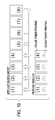
- FIG. 12 is a diagram illustrating an operation at the time that 2-up specifying is performed by the user with the printer driver 202, with the embodiment of the optional page specifying (specifying pages 3, 5, 8) shown in Fig. 11 .
- the data of the first page has no clear toner data, but the data of the second page has to print the data of the third page with clear toner. Therefore, in the event of performing 2-up, the data of the first and second pages are set as a page layout of 2-up. Page layout such as shown in Fig. 12 is performed so that the data of the third page exactly layers over the data of the second page, and clear toner printing specifying is performed.
- the data of the fifth page is data to print with clear toner, so as shown in Fig. 12
- the data of the fourth page and the data of the sixth page is set as 2-up on the same sheet.
- Page layout is performed so that the data of the fifth page exactly layers over the data of the fourth page, and clear toner printing specifying is performed. Consequently, the printer driver 202 performs specifying that is the same as the case of specifying clear toner printing of pages 2, 4, and 6 of full 6 pages worth of data, such as shown in Fig. 12 .
- the printer driver 202 renumbers all of the pages from the logical page number 1. At this time the pages specified in the list box 704 are skipped and the page numbers are renumbered.
- the printer driver 202 uses the newly numbered logical page numbers to perform a normal 2-up page layout as to the physical pages.
- the printer driver 202 looks up the logical page numbers assigned to the previous page of the page thereof.
- the printer driver 202 searches the physical page where the page thereof is laid out, and inserts one page worth of a physical page for clear toner after the page thereof. Note that in the event that a physical page for clear toner is already inserted, the printer driver 202 does not perform inserting of a physical page for clear toner.
- the printer driver 202 lays out each page specified with the list box 704 with a 2-up page layout on the inserted physical pages for clear toner.
- the printer driver 202 at this time performs 2-up processing so that the physical page is layered on top of the logical page as specified by the user, and the portions having no clear toner pages do not perform drawing.
- the printer driver 202 performs "specify clearing optional pages" processing again as to a job of the new physical pages thus created, thereby realizing 2-up.
- the physical pages for clear toner inserted in the above sequence as optional pages specifying clear toner printing are specified.
- pages 2, 4, and 6 of a total of six pages worth of data are specified for clear toner printing.
- the printer driver 202 performs controls to lay out the color toner pages on the printing face of the sheet with N-up, while laying out the clear toner pages corresponding to the layout of the color toner pages to be printed that are layered with the clear toner pages.
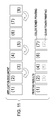
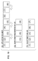
- Fig. 13 is a diagram illustrating an operation at the time that specifying for saddle-stitch binding printing is performed by the user with the printer driver 202, with the embodiment of the optional page specifying (specifying pages 3, 5, 8) shown in Fig. 11 .
- Fig. 13 is similar to the 2-up example shown in Fig. 12 from the point that the data of the third page is layered over the data of the second page precisely, and the data of the fifth page is layered over the data of the fourth page precisely.
- the printer driver 202 performs the same specifying as to the printer 150 as in the case of specifying clear toner printing for pages 3, 5, and 7 to the data of all seven pages, as shown in Fig. 13 .
- the printer driver 202 performs control to lay out the color toner pages so as to perform saddle-stitch binding printing on both faces of the sheet, and lay out the clear toner pages to correspond to the layout of the color toner pages that are layered with the clear toner pages and printed.
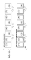
- Fig. 14 is a diagram illustrating an operation with the printer driver 202 at the time that "print page numbers” 806 is specified as “lower center” on a "page design” setting screen 802 of the "page options" dialog box 501 illustrated in Fig. 8 .
- the third, fifth, and eighth pages of the application document 1301 are clear toner data layered over the previous second, fourth, and seventh pages, whereby the printer driver 202 skips such pages and numbers the pages.
- the printer driver 202 adds the drawing data of the page number "3" to the fourth page of the application document to the PDL data, as shown in the time of page number printing 1302. Also, the printer driver 202 adds the drawing data of the page number "4" to the sixth page of the application document to the PDL data. Further, the printer driver 202 adds the drawing data of the page number "5" to the seventh page of the application document to the PDL data.
- the printer driver 202 processes to add a page number to the color toner page, and also as shown with the time of page number printing (time of specifying metallic color) 1303, controls to add a page number as to the clear toner page, corresponding to the page number added to the color toner page for printing layered with the clear toner page. Consequently, page number output having the effect of a reflective surface (page number having gloss) can be obtained.
- the binding margin at the time of specifying duplex printing has an appropriate blank margin created on each edge portion according to the printing face. That is to say, in the case that the odd-numbered pages corresponding to the front face is to have a blank margin created on the left edge portion, the even-numbered pages corresponding to the back face thereof have a blank margin created on the right edge portion.
- the clear toner pages of 3, 5, and 8 are to be layered over pages 2, 4, and 7, whereby the printer driver 202 creates a blank margin 1401 on the left edge portion of pages 1, 4, 5, 7, and 8, and creates a blank margin 1402 on the right edge portion of pages 2, 3, and 6. That is to say, the blank margins on optional pages are determined depending on whether the value subtracting the number of clear toner pages specified before such page from the number of pages is an even number or an odd number.
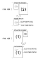
- Figs. 16A and 16B are diagrams illustrating operations in the case that sheet size for page data for color toner and for page data for clear toner to be layered thereupon differs.
- the printer driver 202 cuts off the drawing data by the amount protruding with the upper left as an origin point, and prints, as shown in the printing results.
- the printer driver 202 layers and prints with the upper left as the origin point, as shown in the printing results.
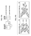
- 1602 in Fig. 17B indicates a spool file of the job issued according to an embodiment of the present invention.
- the drawing data (1) 16023 and drawing data (2) 16025 are both surrounded by one 16022 and 16027. This indicates that the type of toner differs but both are to be printed on the same page.
- step S2004 the printer driver 202 issues a page start command.
- step S2005 determines whether the page to be process is a clear page.
- the printer driver 202 issues a clear start command first, since the page there becomes a page having no color toner (S2013).
- step S2014 the printer driver 202 converts the objects drawn from the application 200 all into PDL and issues a drawing command.
- the present embodiment requires a device to receive a job creating a clear file within the printer 150 (clear toner page registration job) and a job using the specified clear file to perform partial clear printing (color toner page job). This assumes that the device is similar to that of the time wherein "specify with a different job" 620 in Fig. 6 is performed. The operation details within the printer in the event of receiving these jobs are omitted.
- step S1802 the CPU 101 creates a blank color page list and clear page list within the RAM 102. These are lists for the purpose of sequentially connecting the page data output with each of the color toner page job 1703 and clear toner page registration job 1702.
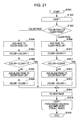
- Fig. 23 is a flowchart describing processing for the printer driver 202 to automatically generate a clear toner page from a color toner page according to the third embodiment of the present invention.
- the color toner page and clear toner page are individually transmitted as two jobs. That is to say, the function shown in the flowchart is realized by the CPU 101 loading the printer drive program recorded in the external memory 111 to the RAM 102 and executing it.
- the printer driver 202 performs control so as to repeat steps S2203 through S2206 for all of the DDI functions detected within the page to be processed (LOOP 2:52202, S2206a).
- the DrvBitblt function for drawing an image is defined as the clear page DDI function.
- the clear page DDI function definition list is fixedly defined, the user can manually make modifications with the user interface or the like of the printer driver 202.
- the printer driver 202 generates a clear toner page manually with a following process (S2209) according to the drawing commands shown with the clear page DDI function.
- step S2204 determines whether the DDI function detected in step S2203 is a clear page DDI function. If the printer driver 202 advances the processing to step S2205.
- the printer driver 202 performs automatic generation of a clear page in step S2009.
- the printer driver 202 automatically generates a clear page according to the drawing command of the DDI function included in the clear page DDI function list.
- step S2210 the printer driver 202 adds the clear page automatically generated in step S2209 to the clear page list in the RAM 102, and advances the processing to step S2211.
- step S2211 the printer driver 202 empties the content of the clear page DDI function list.
- step S2212 the printer driver 202 shifts the page to be processed to the next page, and shifts the processing to step S2201.
- the printer driver 202 ends the processing in the flowchart.
- the printer driver 202 thus adds a clear page or blank page to the clear page list as to all of the pages drawn from the application 200. Consequently, the clear toner page registration job 2104 in Fig. 22 is automatically generated by the printer driver 202. Subsequently, similar to the above-described second embodiment, printing instructions are performed as to the printer 150 with two jobs (color toner page job 2102, clear toner page registration job 2103).
- FIG. 25 is a schematic diagram illustrating the difference in clear toner page registration jobs generated with the third embodiment and the fourth embodiment of the present invention.
- a clear page of the same printed image is generated on the second page and the fifth page, whereby unnecessary communication is generated at the time of printing.
- a clear page having the same printed image is not generated, thereby omitting unnecessary communication. This is also effective in a case wherein multiple copies are specified with the printer driver 202.
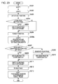
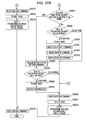
- Fig. 26 is a flowchart describing processing for the printer driver 202 to automatically generate a clear toner page from a color toner page according to the fourth embodiment of the present invention. That is to say, the function shown on the flowchart is realized by the CPU 101 loading on the RAM 102 and executing the printer driver program recorded in the external memory 111. Note that in Fig. 26 the same steps as those in Fig. 23 are referenced with the same step numbers. Hereafter, only the differences with Fig. 23 will be described.
- the printer driver 202 executed with the CPU 101 (hereafter simply called the printer driver 202) advances the processing to step S2501.
- step S2501 the printer driver 202 determines whether or not the size of the clear page DDI function list is 0.
- step S2501 In the case determination is made in step S2501 that the size of the clear page DDI function list is 0, the printer driver 202 advances the processing without change to step S2502.
- step S2501 determines whether the size of the clear page DDI function list is not 0, the printer driver 202 advances the processing without change to step S2503.
- step S2503 the printer driver 202 determines whether or not that which is similar to the clear page DDI function list of the page currently being analyzed is included in the DDI function list saved in the RAM 102.
- the saved DDI function list will now be described with reference to Fig. 27 .
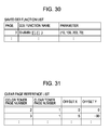
- Fig. 27 is a diagram schematically illustrating a DDI function list saved within the RAM 102.
- the name of the clear page DDI function detected for each page, the parameters, and detected page numbers, are stored in the saved DDI function list (stored in the later-described step S2506).
- the printer driver 202 performs the determination in step S2503 in Fig. 26 described above, based on the information herein.
- Fig. 27 shows a state of the saved DDI function list at the point-in-time that the analysis has ended for up to the fourth page of the application document 2101 shown in Fig. 22 .
- the DDI function "DrvBitBlt (10, 100, 200, 70)" is stored in the clear page DDI function list. This matches the content of the first row of the saved DDI function list, whereby in step S2503 in Fig. 26 is determined as "match with saved DDI function list".
- step S2503 determines that that which is similar as the clear page DDI function list in the page currently being analyzed is included in the saved DDI function list.
- step S2505 the printer driver 202 adds the clear page generated in step S2504 to the clear page list.
- step S2502 the printer driver 202 empties the content of the clear page DDI function list, in step S2212 shift the page to be processed to the next page, and shifts the processing to step S2201.
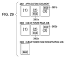
- a fifth embodiment of the present invention will be described with reference to Figs. 29 through 31 .
- determination is made simply as to whether or not the printed images are the same, thereby preventing duplication of generating clear toner pages.
- a processing method differs in that determination is made only as to whether or not the object shape and size of the object drawn with the DDI function are the same.
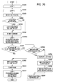
- the portions differing from the above-described fourth embodiment are only steps S2503 and S2507 in Fig. 26 . Only the portions differing from the fourth embodiment will be described below with reference to Figs. 26 and 30 .
- the printer driver 202 performs comparison with focus only on the portion related to the size of the DrvBitBlt command. That is to say, the clear page DDI function list is width: 200 and height: 70, and the page 2 of the saved DDI function list in Fig. 30 is also width: 200 and height: 70, so are determined to be the same (match). That is to say, processing is advanced to step S2507. Note that the brackets ([]) in the function named in Fig. 30 indicate that comparison of such portion is to be omitted.
- Fig. 31 is a diagram illustrating content of an updated clear page reference list.
- X coordinate difference and Y coordinate difference of the DrvBitBlt function which are found in the event of comparing the saved DDI function list and clear page DDI function list in step S2503 in Fig. 26 , are stored in the offset X and offset Y.
- the printer driver 202 transmits the clear page reference list updated in step S2507 in Fig. 26 to the printer 150.
- the printer 150 shifts the page of the instructed clear toner page number the amount of the instructed offset to overlay on the color page and prints, based on the clear page reference list information transmitted from the printer driver 202.
- the clear toner page specifying processing and print job generating processing differ from the above-described first and second embodiment. Accordingly, the differing processing will be described in detail.
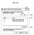
- the region 611 of the page to be printed with clear toner has a "specify page” button 626.
- the printer driver 202 displays the dialog box 3101 shown in the later-described Fig. 33 on the CRT 110.
- the dialog box 3101 arbitrary/optional pages which are not to be subject to clear toner printing out of the even-numbered pages or odd-numbered pages can be specified as non-clear toner pages.
- Fig. 35A the same drawing data is included in the even-numbered pages 3309 and 3310 of the application document. Note that page 4 (3310) in Fig. 35A is specified as a non-clear toner page.
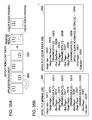
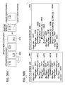
- 3302 in Fig. 35B shows a first example of the spool file of a job issued using the present embodiment.
- page 4 (3310) in Fig. 35A is specified as a non-clear toner page.
- the job is surrounded by two commands of 33031 and 33042.
- the drawing data (1) 33036 is surrounded by 33035 and 33037 of the first page. This indicates that the drawing data (1) is printed using color toner with the data for color toner of the first page.
- the drawing data (3) 34039 is printed on the second page with color toner, but the blank page non-charge setting (3) 34040 is included in 34038 and 34041 of the second page, whereby the second page is not printed with clear toner.
- step S3510 In the case determination is made in step S3510 that the clear page to be layered over the page (the page to be processed) is specified as a "non-clear toner page", the printer driver 202 advances the processing to step S3511.
- the program can be supplied by using a browser on a client computer to connect to a website on the Internet, and downloading the program itself of embodiments of the present invention from the website thereof to a computer-readable storage medium such as a hard disk.
- the program can by supplied by downloading a file including an automatic installation function that has been compressed from the website onto a computer-readable storage medium such as a hard disk.
- the program code making up the program of embodiments of the present invention can be divided into multiple files, and can be downloaded from different websites for each file. That is to say, a WWW server and FTP server and the like which enable downloading program files for causing a computer to realize the function processing of embodiments of the present invention as to multiple users are also included in the scope of the present invention.
Applications Claiming Priority (1)
| Application Number | Priority Date | Filing Date | Title |
|---|---|---|---|
| JP2008180983A JP5121611B2 (ja) | 2008-07-11 | 2008-07-11 | 印刷制御装置、印刷制御方法、及びプログラム |
Publications (2)
| Publication Number | Publication Date |
|---|---|
| EP2144154A2 true EP2144154A2 (fr) | 2010-01-13 |
| EP2144154A3 EP2144154A3 (fr) | 2012-10-24 |
Family
ID=41130311
Family Applications (1)
| Application Number | Title | Priority Date | Filing Date |
|---|---|---|---|
| EP09165207A Withdrawn EP2144154A3 (fr) | 2008-07-11 | 2009-07-10 | Appareil de commande d'impression, procédé de commande d'impression et son programme |
Country Status (5)
| Country | Link |
|---|---|
| US (1) | US8400680B2 (fr) |
| EP (1) | EP2144154A3 (fr) |
| JP (1) | JP5121611B2 (fr) |
| KR (1) | KR101120344B1 (fr) |
| CN (1) | CN101625630B (fr) |
Cited By (2)
| Publication number | Priority date | Publication date | Assignee | Title |
|---|---|---|---|---|
| EP3726826A1 (fr) * | 2019-04-18 | 2020-10-21 | Ricoh Company, Ltd. | Appareil de formation d'images, appareil de traitement d'informations, système d'impression, procédé d'impression et programme |
| US11190668B2 (en) * | 2019-06-25 | 2021-11-30 | Ricoh Company, Ltd. | Image processing apparatus, printing system, method for embedding latent image, and storage medium |
Families Citing this family (26)
| Publication number | Priority date | Publication date | Assignee | Title |
|---|---|---|---|---|
| JP5375575B2 (ja) * | 2009-12-14 | 2013-12-25 | 富士ゼロックス株式会社 | 画像形成制御装置、画像形成装置、画像形成システム、及びプログラム |
| JP4997300B2 (ja) * | 2010-02-24 | 2012-08-08 | 京セラドキュメントソリューションズ株式会社 | 操作装置及び画像形成装置 |
| JP5680909B2 (ja) | 2010-08-31 | 2015-03-04 | キヤノン株式会社 | 印刷制御装置及びその制御方法 |
| JP5582928B2 (ja) | 2010-08-31 | 2014-09-03 | キヤノン株式会社 | 印刷システム、印刷制御装置及びその制御方法 |
| JP5794062B2 (ja) * | 2010-09-15 | 2015-10-14 | 株式会社リコー | 情報処理装置、データ生成方法及びプログラム |
| JP6132004B2 (ja) * | 2011-03-18 | 2017-05-24 | 株式会社リコー | 印刷制御装置、印刷システム、印刷制御方法およびプログラム |
| US8675259B2 (en) * | 2011-11-23 | 2014-03-18 | Xerox Corporation | Double layer glossmark image through dynamic patterninks |
| US9174294B2 (en) | 2012-03-30 | 2015-11-03 | Illinois Tool Works Inc. | Devices and methods for analyzing spatter generating events |
| US20160009105A1 (en) * | 2013-03-29 | 2016-01-14 | Seiko Epson Corporation | Print Control Device, Printing Device, Data Processing Method, and Print Control Device Configuration Method |
| JP5697714B2 (ja) | 2013-05-30 | 2015-04-08 | シャープ株式会社 | 設定装置、その設定装置を備えた画像形成装置、及びクリアコート設定方法 |
| JP6355419B2 (ja) | 2014-05-14 | 2018-07-11 | キヤノン株式会社 | 画像処理装置及び画像処理方法 |
| JP6198209B2 (ja) * | 2015-02-10 | 2017-09-20 | シャープ株式会社 | 設定装置、その設定装置を備えた画像形成装置、及びクリアコート設定方法 |
| US10284036B2 (en) * | 2015-08-24 | 2019-05-07 | GM Global Technology Operations LLC | Electric machine for hybrid powertrain with engine belt drive |
| CN107463393B (zh) * | 2016-06-06 | 2020-08-25 | 富士施乐实业发展(中国)有限公司 | 外围设备及其驱动程序安装方法和系统 |
| JP2017228838A (ja) * | 2016-06-20 | 2017-12-28 | キヤノン株式会社 | 画像処理装置、画像処理方法及びプログラム |
| JP2018144361A (ja) | 2017-03-07 | 2018-09-20 | キヤノン株式会社 | 画像形成装置、画像形成装置の制御方法、及びプログラム |
| JP2018144372A (ja) * | 2017-03-07 | 2018-09-20 | キヤノン株式会社 | 画像形成装置、画像形成装置の制御方法、及びプログラム |
| US10255011B2 (en) * | 2017-03-10 | 2019-04-09 | Xerox Corporation | Methods and systems for applying spot color on one or more pages as specified by a user |
| US10559989B2 (en) * | 2017-08-07 | 2020-02-11 | Schaeffler Technologies AG & Co. KG | Rotor carrier and locking diaphragm spring |
| JP2017207780A (ja) * | 2017-08-15 | 2017-11-24 | シャープ株式会社 | 設定装置及びクリアコート設定方法 |
| JP6992403B2 (ja) * | 2017-10-23 | 2022-01-13 | 株式会社リコー | 印刷制御装置、印刷システム、印刷制御方法、及びプログラム |
| JP7013862B2 (ja) * | 2017-12-27 | 2022-02-01 | 株式会社リコー | 情報処理装置 |
| JP7198095B2 (ja) * | 2019-01-30 | 2022-12-28 | 理想科学工業株式会社 | 印刷システム |
| JP2019074767A (ja) * | 2019-02-12 | 2019-05-16 | シャープ株式会社 | 設定装置、その設定装置を備えた画像形成装置、及びクリアコート設定方法 |
| JP7358917B2 (ja) | 2019-10-31 | 2023-10-11 | 株式会社リコー | 印刷システム、プログラム、画像形成装置、及び、印刷方法 |
| JP2023110340A (ja) * | 2022-01-28 | 2023-08-09 | セイコーエプソン株式会社 | 情報処理装置、情報処理方法、プログラム |
Citations (2)
| Publication number | Priority date | Publication date | Assignee | Title |
|---|---|---|---|---|
| US20020101599A1 (en) * | 1997-11-05 | 2002-08-01 | Satoshi Okimoto | Print system for executing printing operations based on macros selectively designated on document set basis |
| US20070024880A1 (en) | 2005-07-27 | 2007-02-01 | Canon Kabushiki Kaisha | Image processing apparatus and method therefor |
Family Cites Families (13)
| Publication number | Priority date | Publication date | Assignee | Title |
|---|---|---|---|---|
| DE19731968A1 (de) * | 1997-07-24 | 1999-01-28 | Giesecke & Devrient Gmbh | Sicherheitsdokument |
| DE19819571A1 (de) * | 1998-04-30 | 1999-11-04 | Giesecke & Devrient Gmbh | Wertdokument mit Sicherheitselement |
| JP2003162520A (ja) * | 2001-09-14 | 2003-06-06 | Canon Inc | 情報処理装置及び方法 |
| JP4045850B2 (ja) | 2002-04-30 | 2008-02-13 | セイコーエプソン株式会社 | テーププリンタのキャラクタ処理方法およびテーププリンタ |
| JP4266766B2 (ja) | 2003-10-10 | 2009-05-20 | キヤノン株式会社 | 情報処理装置および情報処理方法 |
| US7352493B2 (en) | 2003-12-12 | 2008-04-01 | Xerox Corporation | Enhancement of glossmark images at low and high densities |
| JP2005225124A (ja) * | 2004-02-13 | 2005-08-25 | Ricoh Printing Systems Ltd | 印刷制御装置及び記憶媒体 |
| JP2004314645A (ja) * | 2004-08-16 | 2004-11-11 | Toppan Printing Co Ltd | フルカラースクラッチオフ籤券 |
| JP2006163054A (ja) | 2004-12-08 | 2006-06-22 | Kyocera Mita Corp | カラー印刷装置 |
| JP2006309685A (ja) | 2005-03-31 | 2006-11-09 | Seiko Epson Corp | 印刷システム、プログラム及び記録媒体 |
| JP2007124077A (ja) * | 2005-10-26 | 2007-05-17 | Fuji Xerox Co Ltd | 画像合成方法および画像形成装置 |
| US20070268511A1 (en) | 2006-05-19 | 2007-11-22 | Eastman Kodak Company | Secure document printing |
| JP2008145453A (ja) * | 2006-12-05 | 2008-06-26 | Canon Inc | 画像形成システムおよび画像形成装置 |
-
2008
- 2008-07-11 JP JP2008180983A patent/JP5121611B2/ja active Active
-
2009
- 2009-07-10 US US12/501,236 patent/US8400680B2/en active Active
- 2009-07-10 KR KR1020090063214A patent/KR101120344B1/ko active IP Right Grant
- 2009-07-10 EP EP09165207A patent/EP2144154A3/fr not_active Withdrawn
- 2009-07-13 CN CN2009101521448A patent/CN101625630B/zh active Active
Patent Citations (2)
| Publication number | Priority date | Publication date | Assignee | Title |
|---|---|---|---|---|
| US20020101599A1 (en) * | 1997-11-05 | 2002-08-01 | Satoshi Okimoto | Print system for executing printing operations based on macros selectively designated on document set basis |
| US20070024880A1 (en) | 2005-07-27 | 2007-02-01 | Canon Kabushiki Kaisha | Image processing apparatus and method therefor |
Cited By (3)
| Publication number | Priority date | Publication date | Assignee | Title |
|---|---|---|---|---|
| EP3726826A1 (fr) * | 2019-04-18 | 2020-10-21 | Ricoh Company, Ltd. | Appareil de formation d'images, appareil de traitement d'informations, système d'impression, procédé d'impression et programme |
| US11039039B2 (en) | 2019-04-18 | 2021-06-15 | Ricoh Company, Ltd. | Apparatus, system, and product for converting designated image area with object for printing in a spot color into printing data |
| US11190668B2 (en) * | 2019-06-25 | 2021-11-30 | Ricoh Company, Ltd. | Image processing apparatus, printing system, method for embedding latent image, and storage medium |
Also Published As
| Publication number | Publication date |
|---|---|
| CN101625630A (zh) | 2010-01-13 |
| JP5121611B2 (ja) | 2013-01-16 |
| CN101625630B (zh) | 2012-03-07 |
| KR20100007803A (ko) | 2010-01-22 |
| JP2010020578A (ja) | 2010-01-28 |
| US20100007902A1 (en) | 2010-01-14 |
| EP2144154A3 (fr) | 2012-10-24 |
| KR101120344B1 (ko) | 2012-02-29 |
| US8400680B2 (en) | 2013-03-19 |
Similar Documents
| Publication | Publication Date | Title |
|---|---|---|
| EP2144154A2 (fr) | Appareil de commande d'impression, procédé de commande d'impression et son programme | |
| KR100524568B1 (ko) | 인쇄 제어 장치 및 그 표시 방법 | |
| JP4834256B2 (ja) | 情報処理装置および印刷データ生成方法および印刷制御プログラムおよび記憶媒体 | |
| US6934046B1 (en) | Information processor, method for processing information and memory medium for storing program readable by computer | |
| JP3634695B2 (ja) | 印刷制御方法および装置 | |
| JP3937666B2 (ja) | 印刷制御方法および装置 | |
| US7535591B2 (en) | Print control method, apparatus and program for displaying a preview image | |
| JP4143426B2 (ja) | 文書処理装置及び方法 | |
| JP3880307B2 (ja) | 情報処理装置および方法 | |
| JP5677043B2 (ja) | 情報処理装置、情報処理方法及びプログラム | |
| US8002258B2 (en) | Tab sheet insertion apparatus | |
| US20030007181A1 (en) | Information processing apparatus and control method therefor | |
| US8218191B2 (en) | Computer readable recording medium stored with control program for controlling image forming apparatus having a tab sheet insertion function, image forming apparatus and method executed in the image forming apparatus | |
| JP3673684B2 (ja) | 情報処理装置、情報処理方法およびコンピュータ読み取り可能なプログラムを格納した記憶媒体 | |
| JP4612917B2 (ja) | 制御方法及び情報処理装置及びコンピュータ読み出し可能な記録媒体 | |
| US8111410B2 (en) | Data processing apparatus, and computer readable recording medium stored with processing program | |
| JP4973460B2 (ja) | 印刷ジョブ実行装置、印刷ジョブ実行装置で使用される方法、および印刷ジョブ実行装置で実行されるコンピュータプログラム | |
| US8526043B2 (en) | Printing system, printing method, and printing control apparatus for splitting document | |
| JP4612909B2 (ja) | 制御方法及び情報処理装置及びコンピュータ読み出し可能な記録媒体 | |
| JP2010211829A (ja) | 情報処理装置と情報処理方法及びコンピュータ読み出し可能な記録媒体 | |
| JP2004157610A (ja) | 情報処理装置 |
Legal Events
| Date | Code | Title | Description |
|---|---|---|---|
| PUAI | Public reference made under article 153(3) epc to a published international application that has entered the european phase |
Free format text: ORIGINAL CODE: 0009012 |
|
| AK | Designated contracting states |
Kind code of ref document: A2 Designated state(s): AT BE BG CH CY CZ DE DK EE ES FI FR GB GR HR HU IE IS IT LI LT LU LV MC MK MT NL NO PL PT RO SE SI SK SM TR |
|
| PUAL | Search report despatched |
Free format text: ORIGINAL CODE: 0009013 |
|
| AK | Designated contracting states |
Kind code of ref document: A3 Designated state(s): AT BE BG CH CY CZ DE DK EE ES FI FR GB GR HR HU IE IS IT LI LT LU LV MC MK MT NL NO PL PT RO SE SI SK SM TR |
|
| AX | Request for extension of the european patent |
Extension state: AL BA RS |
|
| RIC1 | Information provided on ipc code assigned before grant |
Ipc: G06F 3/12 20060101AFI20120917BHEP |
|
| 17P | Request for examination filed |
Effective date: 20130424 |
|
| 17Q | First examination report despatched |
Effective date: 20170901 |
|
| STAA | Information on the status of an ep patent application or granted ep patent |
Free format text: STATUS: THE APPLICATION HAS BEEN WITHDRAWN |
|
| 18W | Application withdrawn |
Effective date: 20190227 |