EP2138233B1 - Mikrofluidische Folienstruktur zum Dosierren von Flüssigkeiten - Google Patents
Mikrofluidische Folienstruktur zum Dosierren von Flüssigkeiten Download PDFInfo
- Publication number
- EP2138233B1 EP2138233B1 EP20080010082 EP08010082A EP2138233B1 EP 2138233 B1 EP2138233 B1 EP 2138233B1 EP 20080010082 EP20080010082 EP 20080010082 EP 08010082 A EP08010082 A EP 08010082A EP 2138233 B1 EP2138233 B1 EP 2138233B1
- Authority
- EP
- European Patent Office
- Prior art keywords
- substrate
- film
- chamber
- structure according
- microfluidic structure
- Prior art date
- Legal status (The legal status is an assumption and is not a legal conclusion. Google has not performed a legal analysis and makes no representation as to the accuracy of the status listed.)
- Active
Links
Images


Classifications
-
- F—MECHANICAL ENGINEERING; LIGHTING; HEATING; WEAPONS; BLASTING
- F16—ENGINEERING ELEMENTS AND UNITS; GENERAL MEASURES FOR PRODUCING AND MAINTAINING EFFECTIVE FUNCTIONING OF MACHINES OR INSTALLATIONS; THERMAL INSULATION IN GENERAL
- F16K—VALVES; TAPS; COCKS; ACTUATING-FLOATS; DEVICES FOR VENTING OR AERATING
- F16K99/00—Subject matter not provided for in other groups of this subclass
- F16K99/0001—Microvalves
-
- B—PERFORMING OPERATIONS; TRANSPORTING
- B01—PHYSICAL OR CHEMICAL PROCESSES OR APPARATUS IN GENERAL
- B01L—CHEMICAL OR PHYSICAL LABORATORY APPARATUS FOR GENERAL USE
- B01L3/00—Containers or dishes for laboratory use, e.g. laboratory glassware; Droppers
- B01L3/50—Containers for the purpose of retaining a material to be analysed, e.g. test tubes
- B01L3/502—Containers for the purpose of retaining a material to be analysed, e.g. test tubes with fluid transport, e.g. in multi-compartment structures
- B01L3/5027—Containers for the purpose of retaining a material to be analysed, e.g. test tubes with fluid transport, e.g. in multi-compartment structures by integrated microfluidic structures, i.e. dimensions of channels and chambers are such that surface tension forces are important, e.g. lab-on-a-chip
- B01L3/502707—Containers for the purpose of retaining a material to be analysed, e.g. test tubes with fluid transport, e.g. in multi-compartment structures by integrated microfluidic structures, i.e. dimensions of channels and chambers are such that surface tension forces are important, e.g. lab-on-a-chip characterised by the manufacture of the container or its components
-
- B—PERFORMING OPERATIONS; TRANSPORTING
- B01—PHYSICAL OR CHEMICAL PROCESSES OR APPARATUS IN GENERAL
- B01L—CHEMICAL OR PHYSICAL LABORATORY APPARATUS FOR GENERAL USE
- B01L3/00—Containers or dishes for laboratory use, e.g. laboratory glassware; Droppers
- B01L3/50—Containers for the purpose of retaining a material to be analysed, e.g. test tubes
- B01L3/502—Containers for the purpose of retaining a material to be analysed, e.g. test tubes with fluid transport, e.g. in multi-compartment structures
- B01L3/5027—Containers for the purpose of retaining a material to be analysed, e.g. test tubes with fluid transport, e.g. in multi-compartment structures by integrated microfluidic structures, i.e. dimensions of channels and chambers are such that surface tension forces are important, e.g. lab-on-a-chip
- B01L3/502738—Containers for the purpose of retaining a material to be analysed, e.g. test tubes with fluid transport, e.g. in multi-compartment structures by integrated microfluidic structures, i.e. dimensions of channels and chambers are such that surface tension forces are important, e.g. lab-on-a-chip characterised by integrated valves
-
- B—PERFORMING OPERATIONS; TRANSPORTING
- B29—WORKING OF PLASTICS; WORKING OF SUBSTANCES IN A PLASTIC STATE IN GENERAL
- B29C—SHAPING OR JOINING OF PLASTICS; SHAPING OF MATERIAL IN A PLASTIC STATE, NOT OTHERWISE PROVIDED FOR; AFTER-TREATMENT OF THE SHAPED PRODUCTS, e.g. REPAIRING
- B29C65/00—Joining or sealing of preformed parts, e.g. welding of plastics materials; Apparatus therefor
- B29C65/02—Joining or sealing of preformed parts, e.g. welding of plastics materials; Apparatus therefor by heating, with or without pressure
- B29C65/18—Joining or sealing of preformed parts, e.g. welding of plastics materials; Apparatus therefor by heating, with or without pressure using heated tools
-
- B—PERFORMING OPERATIONS; TRANSPORTING
- B29—WORKING OF PLASTICS; WORKING OF SUBSTANCES IN A PLASTIC STATE IN GENERAL
- B29C—SHAPING OR JOINING OF PLASTICS; SHAPING OF MATERIAL IN A PLASTIC STATE, NOT OTHERWISE PROVIDED FOR; AFTER-TREATMENT OF THE SHAPED PRODUCTS, e.g. REPAIRING
- B29C66/00—General aspects of processes or apparatus for joining preformed parts
- B29C66/01—General aspects dealing with the joint area or with the area to be joined
- B29C66/05—Particular design of joint configurations
- B29C66/10—Particular design of joint configurations particular design of the joint cross-sections
- B29C66/11—Joint cross-sections comprising a single joint-segment, i.e. one of the parts to be joined comprising a single joint-segment in the joint cross-section
- B29C66/112—Single lapped joints
- B29C66/1122—Single lap to lap joints, i.e. overlap joints
-
- B—PERFORMING OPERATIONS; TRANSPORTING
- B29—WORKING OF PLASTICS; WORKING OF SUBSTANCES IN A PLASTIC STATE IN GENERAL
- B29C—SHAPING OR JOINING OF PLASTICS; SHAPING OF MATERIAL IN A PLASTIC STATE, NOT OTHERWISE PROVIDED FOR; AFTER-TREATMENT OF THE SHAPED PRODUCTS, e.g. REPAIRING
- B29C66/00—General aspects of processes or apparatus for joining preformed parts
- B29C66/01—General aspects dealing with the joint area or with the area to be joined
- B29C66/32—Measures for keeping the burr form under control; Avoiding burr formation; Shaping the burr
- B29C66/328—Leaving the burrs unchanged for providing particular properties to the joint, e.g. as decorative effect
-
- B—PERFORMING OPERATIONS; TRANSPORTING
- B29—WORKING OF PLASTICS; WORKING OF SUBSTANCES IN A PLASTIC STATE IN GENERAL
- B29C—SHAPING OR JOINING OF PLASTICS; SHAPING OF MATERIAL IN A PLASTIC STATE, NOT OTHERWISE PROVIDED FOR; AFTER-TREATMENT OF THE SHAPED PRODUCTS, e.g. REPAIRING
- B29C66/00—General aspects of processes or apparatus for joining preformed parts
- B29C66/50—General aspects of joining tubular articles; General aspects of joining long products, i.e. bars or profiled elements; General aspects of joining single elements to tubular articles, hollow articles or bars; General aspects of joining several hollow-preforms to form hollow or tubular articles
- B29C66/51—Joining tubular articles, profiled elements or bars; Joining single elements to tubular articles, hollow articles or bars; Joining several hollow-preforms to form hollow or tubular articles
- B29C66/53—Joining single elements to tubular articles, hollow articles or bars
- B29C66/534—Joining single elements to open ends of tubular or hollow articles or to the ends of bars
- B29C66/5346—Joining single elements to open ends of tubular or hollow articles or to the ends of bars said single elements being substantially flat
- B29C66/53461—Joining single elements to open ends of tubular or hollow articles or to the ends of bars said single elements being substantially flat joining substantially flat covers and/or substantially flat bottoms to open ends of container bodies
-
- B—PERFORMING OPERATIONS; TRANSPORTING
- B29—WORKING OF PLASTICS; WORKING OF SUBSTANCES IN A PLASTIC STATE IN GENERAL
- B29C—SHAPING OR JOINING OF PLASTICS; SHAPING OF MATERIAL IN A PLASTIC STATE, NOT OTHERWISE PROVIDED FOR; AFTER-TREATMENT OF THE SHAPED PRODUCTS, e.g. REPAIRING
- B29C66/00—General aspects of processes or apparatus for joining preformed parts
- B29C66/70—General aspects of processes or apparatus for joining preformed parts characterised by the composition, physical properties or the structure of the material of the parts to be joined; Joining with non-plastics material
- B29C66/72—General aspects of processes or apparatus for joining preformed parts characterised by the composition, physical properties or the structure of the material of the parts to be joined; Joining with non-plastics material characterised by the structure of the material of the parts to be joined
- B29C66/723—General aspects of processes or apparatus for joining preformed parts characterised by the composition, physical properties or the structure of the material of the parts to be joined; Joining with non-plastics material characterised by the structure of the material of the parts to be joined being multi-layered
-
- F—MECHANICAL ENGINEERING; LIGHTING; HEATING; WEAPONS; BLASTING
- F04—POSITIVE - DISPLACEMENT MACHINES FOR LIQUIDS; PUMPS FOR LIQUIDS OR ELASTIC FLUIDS
- F04B—POSITIVE-DISPLACEMENT MACHINES FOR LIQUIDS; PUMPS
- F04B43/00—Machines, pumps, or pumping installations having flexible working members
- F04B43/02—Machines, pumps, or pumping installations having flexible working members having plate-like flexible members, e.g. diaphragms
- F04B43/04—Pumps having electric drive
- F04B43/043—Micropumps
-
- B—PERFORMING OPERATIONS; TRANSPORTING
- B01—PHYSICAL OR CHEMICAL PROCESSES OR APPARATUS IN GENERAL
- B01L—CHEMICAL OR PHYSICAL LABORATORY APPARATUS FOR GENERAL USE
- B01L2200/00—Solutions for specific problems relating to chemical or physical laboratory apparatus
- B01L2200/06—Fluid handling related problems
- B01L2200/0689—Sealing
-
- B—PERFORMING OPERATIONS; TRANSPORTING
- B01—PHYSICAL OR CHEMICAL PROCESSES OR APPARATUS IN GENERAL
- B01L—CHEMICAL OR PHYSICAL LABORATORY APPARATUS FOR GENERAL USE
- B01L2300/00—Additional constructional details
- B01L2300/08—Geometry, shape and general structure
- B01L2300/0887—Laminated structure
-
- B—PERFORMING OPERATIONS; TRANSPORTING
- B01—PHYSICAL OR CHEMICAL PROCESSES OR APPARATUS IN GENERAL
- B01L—CHEMICAL OR PHYSICAL LABORATORY APPARATUS FOR GENERAL USE
- B01L2400/00—Moving or stopping fluids
- B01L2400/04—Moving fluids with specific forces or mechanical means
- B01L2400/0403—Moving fluids with specific forces or mechanical means specific forces
- B01L2400/0406—Moving fluids with specific forces or mechanical means specific forces capillary forces
-
- B—PERFORMING OPERATIONS; TRANSPORTING
- B01—PHYSICAL OR CHEMICAL PROCESSES OR APPARATUS IN GENERAL
- B01L—CHEMICAL OR PHYSICAL LABORATORY APPARATUS FOR GENERAL USE
- B01L2400/00—Moving or stopping fluids
- B01L2400/04—Moving fluids with specific forces or mechanical means
- B01L2400/0403—Moving fluids with specific forces or mechanical means specific forces
- B01L2400/0442—Moving fluids with specific forces or mechanical means specific forces thermal energy, e.g. vaporisation, bubble jet
-
- B—PERFORMING OPERATIONS; TRANSPORTING
- B01—PHYSICAL OR CHEMICAL PROCESSES OR APPARATUS IN GENERAL
- B01L—CHEMICAL OR PHYSICAL LABORATORY APPARATUS FOR GENERAL USE
- B01L2400/00—Moving or stopping fluids
- B01L2400/06—Valves, specific forms thereof
- B01L2400/0633—Valves, specific forms thereof with moving parts
- B01L2400/0638—Valves, specific forms thereof with moving parts membrane valves, flap valves
-
- B—PERFORMING OPERATIONS; TRANSPORTING
- B01—PHYSICAL OR CHEMICAL PROCESSES OR APPARATUS IN GENERAL
- B01L—CHEMICAL OR PHYSICAL LABORATORY APPARATUS FOR GENERAL USE
- B01L2400/00—Moving or stopping fluids
- B01L2400/06—Valves, specific forms thereof
- B01L2400/0688—Valves, specific forms thereof surface tension valves, capillary stop, capillary break
-
- B—PERFORMING OPERATIONS; TRANSPORTING
- B01—PHYSICAL OR CHEMICAL PROCESSES OR APPARATUS IN GENERAL
- B01L—CHEMICAL OR PHYSICAL LABORATORY APPARATUS FOR GENERAL USE
- B01L2400/00—Moving or stopping fluids
- B01L2400/08—Regulating or influencing the flow resistance
- B01L2400/082—Active control of flow resistance, e.g. flow controllers
-
- B—PERFORMING OPERATIONS; TRANSPORTING
- B01—PHYSICAL OR CHEMICAL PROCESSES OR APPARATUS IN GENERAL
- B01L—CHEMICAL OR PHYSICAL LABORATORY APPARATUS FOR GENERAL USE
- B01L3/00—Containers or dishes for laboratory use, e.g. laboratory glassware; Droppers
- B01L3/50—Containers for the purpose of retaining a material to be analysed, e.g. test tubes
- B01L3/502—Containers for the purpose of retaining a material to be analysed, e.g. test tubes with fluid transport, e.g. in multi-compartment structures
- B01L3/5027—Containers for the purpose of retaining a material to be analysed, e.g. test tubes with fluid transport, e.g. in multi-compartment structures by integrated microfluidic structures, i.e. dimensions of channels and chambers are such that surface tension forces are important, e.g. lab-on-a-chip
- B01L3/50273—Containers for the purpose of retaining a material to be analysed, e.g. test tubes with fluid transport, e.g. in multi-compartment structures by integrated microfluidic structures, i.e. dimensions of channels and chambers are such that surface tension forces are important, e.g. lab-on-a-chip characterised by the means or forces applied to move the fluids
-
- B—PERFORMING OPERATIONS; TRANSPORTING
- B01—PHYSICAL OR CHEMICAL PROCESSES OR APPARATUS IN GENERAL
- B01L—CHEMICAL OR PHYSICAL LABORATORY APPARATUS FOR GENERAL USE
- B01L3/00—Containers or dishes for laboratory use, e.g. laboratory glassware; Droppers
- B01L3/50—Containers for the purpose of retaining a material to be analysed, e.g. test tubes
- B01L3/502—Containers for the purpose of retaining a material to be analysed, e.g. test tubes with fluid transport, e.g. in multi-compartment structures
- B01L3/5027—Containers for the purpose of retaining a material to be analysed, e.g. test tubes with fluid transport, e.g. in multi-compartment structures by integrated microfluidic structures, i.e. dimensions of channels and chambers are such that surface tension forces are important, e.g. lab-on-a-chip
- B01L3/502746—Containers for the purpose of retaining a material to be analysed, e.g. test tubes with fluid transport, e.g. in multi-compartment structures by integrated microfluidic structures, i.e. dimensions of channels and chambers are such that surface tension forces are important, e.g. lab-on-a-chip characterised by the means for controlling flow resistance, e.g. flow controllers, baffles or throttle valves
-
- B—PERFORMING OPERATIONS; TRANSPORTING
- B29—WORKING OF PLASTICS; WORKING OF SUBSTANCES IN A PLASTIC STATE IN GENERAL
- B29C—SHAPING OR JOINING OF PLASTICS; SHAPING OF MATERIAL IN A PLASTIC STATE, NOT OTHERWISE PROVIDED FOR; AFTER-TREATMENT OF THE SHAPED PRODUCTS, e.g. REPAIRING
- B29C66/00—General aspects of processes or apparatus for joining preformed parts
- B29C66/70—General aspects of processes or apparatus for joining preformed parts characterised by the composition, physical properties or the structure of the material of the parts to be joined; Joining with non-plastics material
- B29C66/71—General aspects of processes or apparatus for joining preformed parts characterised by the composition, physical properties or the structure of the material of the parts to be joined; Joining with non-plastics material characterised by the composition of the plastics material of the parts to be joined
-
- B—PERFORMING OPERATIONS; TRANSPORTING
- B29—WORKING OF PLASTICS; WORKING OF SUBSTANCES IN A PLASTIC STATE IN GENERAL
- B29C—SHAPING OR JOINING OF PLASTICS; SHAPING OF MATERIAL IN A PLASTIC STATE, NOT OTHERWISE PROVIDED FOR; AFTER-TREATMENT OF THE SHAPED PRODUCTS, e.g. REPAIRING
- B29C66/00—General aspects of processes or apparatus for joining preformed parts
- B29C66/80—General aspects of machine operations or constructions and parts thereof
- B29C66/81—General aspects of the pressing elements, i.e. the elements applying pressure on the parts to be joined in the area to be joined, e.g. the welding jaws or clamps
- B29C66/814—General aspects of the pressing elements, i.e. the elements applying pressure on the parts to be joined in the area to be joined, e.g. the welding jaws or clamps characterised by the design of the pressing elements, e.g. of the welding jaws or clamps
- B29C66/8141—General aspects of the pressing elements, i.e. the elements applying pressure on the parts to be joined in the area to be joined, e.g. the welding jaws or clamps characterised by the design of the pressing elements, e.g. of the welding jaws or clamps characterised by the surface geometry of the part of the pressing elements, e.g. welding jaws or clamps, coming into contact with the parts to be joined
- B29C66/81411—General aspects of the pressing elements, i.e. the elements applying pressure on the parts to be joined in the area to be joined, e.g. the welding jaws or clamps characterised by the design of the pressing elements, e.g. of the welding jaws or clamps characterised by the surface geometry of the part of the pressing elements, e.g. welding jaws or clamps, coming into contact with the parts to be joined characterised by its cross-section, e.g. transversal or longitudinal, being non-flat
- B29C66/81415—General aspects of the pressing elements, i.e. the elements applying pressure on the parts to be joined in the area to be joined, e.g. the welding jaws or clamps characterised by the design of the pressing elements, e.g. of the welding jaws or clamps characterised by the surface geometry of the part of the pressing elements, e.g. welding jaws or clamps, coming into contact with the parts to be joined characterised by its cross-section, e.g. transversal or longitudinal, being non-flat being bevelled
- B29C66/81419—General aspects of the pressing elements, i.e. the elements applying pressure on the parts to be joined in the area to be joined, e.g. the welding jaws or clamps characterised by the design of the pressing elements, e.g. of the welding jaws or clamps characterised by the surface geometry of the part of the pressing elements, e.g. welding jaws or clamps, coming into contact with the parts to be joined characterised by its cross-section, e.g. transversal or longitudinal, being non-flat being bevelled and flat
-
- B—PERFORMING OPERATIONS; TRANSPORTING
- B29—WORKING OF PLASTICS; WORKING OF SUBSTANCES IN A PLASTIC STATE IN GENERAL
- B29C—SHAPING OR JOINING OF PLASTICS; SHAPING OF MATERIAL IN A PLASTIC STATE, NOT OTHERWISE PROVIDED FOR; AFTER-TREATMENT OF THE SHAPED PRODUCTS, e.g. REPAIRING
- B29C66/00—General aspects of processes or apparatus for joining preformed parts
- B29C66/80—General aspects of machine operations or constructions and parts thereof
- B29C66/81—General aspects of the pressing elements, i.e. the elements applying pressure on the parts to be joined in the area to be joined, e.g. the welding jaws or clamps
- B29C66/814—General aspects of the pressing elements, i.e. the elements applying pressure on the parts to be joined in the area to be joined, e.g. the welding jaws or clamps characterised by the design of the pressing elements, e.g. of the welding jaws or clamps
- B29C66/8141—General aspects of the pressing elements, i.e. the elements applying pressure on the parts to be joined in the area to be joined, e.g. the welding jaws or clamps characterised by the design of the pressing elements, e.g. of the welding jaws or clamps characterised by the surface geometry of the part of the pressing elements, e.g. welding jaws or clamps, coming into contact with the parts to be joined
- B29C66/81411—General aspects of the pressing elements, i.e. the elements applying pressure on the parts to be joined in the area to be joined, e.g. the welding jaws or clamps characterised by the design of the pressing elements, e.g. of the welding jaws or clamps characterised by the surface geometry of the part of the pressing elements, e.g. welding jaws or clamps, coming into contact with the parts to be joined characterised by its cross-section, e.g. transversal or longitudinal, being non-flat
- B29C66/81421—General aspects of the pressing elements, i.e. the elements applying pressure on the parts to be joined in the area to be joined, e.g. the welding jaws or clamps characterised by the design of the pressing elements, e.g. of the welding jaws or clamps characterised by the surface geometry of the part of the pressing elements, e.g. welding jaws or clamps, coming into contact with the parts to be joined characterised by its cross-section, e.g. transversal or longitudinal, being non-flat being convex or concave
- B29C66/81422—General aspects of the pressing elements, i.e. the elements applying pressure on the parts to be joined in the area to be joined, e.g. the welding jaws or clamps characterised by the design of the pressing elements, e.g. of the welding jaws or clamps characterised by the surface geometry of the part of the pressing elements, e.g. welding jaws or clamps, coming into contact with the parts to be joined characterised by its cross-section, e.g. transversal or longitudinal, being non-flat being convex or concave being convex
-
- B—PERFORMING OPERATIONS; TRANSPORTING
- B29—WORKING OF PLASTICS; WORKING OF SUBSTANCES IN A PLASTIC STATE IN GENERAL
- B29C—SHAPING OR JOINING OF PLASTICS; SHAPING OF MATERIAL IN A PLASTIC STATE, NOT OTHERWISE PROVIDED FOR; AFTER-TREATMENT OF THE SHAPED PRODUCTS, e.g. REPAIRING
- B29C66/00—General aspects of processes or apparatus for joining preformed parts
- B29C66/80—General aspects of machine operations or constructions and parts thereof
- B29C66/81—General aspects of the pressing elements, i.e. the elements applying pressure on the parts to be joined in the area to be joined, e.g. the welding jaws or clamps
- B29C66/818—General aspects of the pressing elements, i.e. the elements applying pressure on the parts to be joined in the area to be joined, e.g. the welding jaws or clamps characterised by the cooling constructional aspects, or by the thermal or electrical insulating or conducting constructional aspects of the welding jaws or of the clamps ; comprising means for compensating for the thermal expansion of the welding jaws or of the clamps
- B29C66/8181—General aspects of the pressing elements, i.e. the elements applying pressure on the parts to be joined in the area to be joined, e.g. the welding jaws or clamps characterised by the cooling constructional aspects, or by the thermal or electrical insulating or conducting constructional aspects of the welding jaws or of the clamps ; comprising means for compensating for the thermal expansion of the welding jaws or of the clamps characterised by the cooling constructional aspects
-
- B—PERFORMING OPERATIONS; TRANSPORTING
- B29—WORKING OF PLASTICS; WORKING OF SUBSTANCES IN A PLASTIC STATE IN GENERAL
- B29C—SHAPING OR JOINING OF PLASTICS; SHAPING OF MATERIAL IN A PLASTIC STATE, NOT OTHERWISE PROVIDED FOR; AFTER-TREATMENT OF THE SHAPED PRODUCTS, e.g. REPAIRING
- B29C66/00—General aspects of processes or apparatus for joining preformed parts
- B29C66/80—General aspects of machine operations or constructions and parts thereof
- B29C66/83—General aspects of machine operations or constructions and parts thereof characterised by the movement of the joining or pressing tools
- B29C66/832—Reciprocating joining or pressing tools
- B29C66/8322—Joining or pressing tools reciprocating along one axis
-
- B—PERFORMING OPERATIONS; TRANSPORTING
- B29—WORKING OF PLASTICS; WORKING OF SUBSTANCES IN A PLASTIC STATE IN GENERAL
- B29L—INDEXING SCHEME ASSOCIATED WITH SUBCLASS B29C, RELATING TO PARTICULAR ARTICLES
- B29L2031/00—Other particular articles
- B29L2031/756—Microarticles, nanoarticles
Definitions
- the present invention relates to a structure for dosing a liquid in a microfluidic network according to the preamble of claim 1 and to a method for producing such a structure.
- the present invention is concerned with such microfluidic structures and devices that utilize capillary action or pressure differentials to direct a fluid, and wherein at least a portion of the microfluidic structures consist of chambers and / or channels formed by a foil above a plate-shaped substrate ,
- Valve structures are known from the prior art, in which an elastic membrane for opening and / or closing a microfluidic valve is used.
- the US 5,811,291 describes a microfluidic device that is produced by laminating two polymer films, in particular PE films. In this case, the films are joined together under pressure and heat in some areas, so that chambers and channels can form in unconnected laminating areas by introducing liquid. Subject of the US 5,811,291 is in particular a cuvette.
- the US 2006/0076068 A1 discloses a microfluidic pump and a microfluidic valve, and a method of making the same, wherein the valve is formed by a membrane covering channel structures in a substrate. The valve is made using selective lamination, leaving the membrane unattached in the valve area.
- the US 2006/0057030 A1 discloses a microfluidic device, a so-called MEMS device for transporting liquids from a reservoir, wherein the liquid reservoir is formed in a base plate.
- the base plate with the reservoir and with a channel as liquid-conducting structures is covered by a first polymer film.
- the first polymer film has openings to the reservoir and to the channel.
- a further second polymer film is arranged on the first polymer film, wherein the second film is partially bulged, so that chambers are formed by the curvature.
- These chambers are fluidly separated from each other and filled with air, which breaks through sufficient pressure, for example by compressing the chambers separation points between the first and the second film and the compressed outflowing air displaces the liquid from the reservoir into the channel by means of the openings.
- the US 6,902,706 B1 discloses a valve for controlling a liquid in an analysis chip.
- the valve includes a foil that covers channel ends in a carrier.
- the film is dome-like arched in the region of the channel ends and connects through this dome-like chamber, the channel ends.
- a pneumatic conical actuator By means of a pneumatic conical actuator, the dome can be lowered, whereby the valve is closed.
- the US 2005/0037471 A1 describes a method for manufacturing a microfluidic valve or a microfluidic pump, in which a first channel is molded in a flat elastomeric plastic plate. From a second tool, a second channel is molded in a second elastomeric layer. The first plate is placed with the channel side on the flat and planar surface of the second layer plate and connected thereto. The lower plate is then placed with the still open second channels on a flat and planar support substrate such as on a glass plate. A liquid conducted through the first channel can deflect the membrane formed at the point of intersection of the first and second channels by the elastomeric separating material and thereby acts as a valve.
- the US 2005102058816 A1 discloses a microfluidic diaphragm valve.
- a flexible membrane is used, which is arranged above a flow channel.
- the membrane is deflected and closes the flow channel or releases the flow channel.
- the US 6,293,012 B1 discloses a method for bonding polyimide films under pressure and temperature. When joining a region of a film is pulled by applying a negative pressure to this area in a cavity, so that there is no attachment.
- valve structures or metering elements In order to obtain valve structures or metering elements according to the above-discussed disclosures, it is usually provided to mold channel structures by deformation of an elastomeric film or an elastomeric plastic plate.
- the disadvantage, therefore, therineformenden contours must be introduced with high accuracy in a molding matrix.
- the preparation of such three-dimensional microstructured matrices is costly.
- a further object of the invention is to provide an alternative method for the production of microfluidic structures with structure sizes in the nanometer range or single-digit micrometer range, as well as to provide such structures with improved fluid-conducting properties.
- a valve is usually formed by an element in which an elastic membrane rests on fluid-conducting structures in a carrier substrate and closes these fluid channels in the relaxed state.
- the membrane By applying internal pressure to the liquid or by externally applied pressure on the valve body, the membrane is deflected and releases the fluid path. Furthermore, it is known to mold fluid-conducting structures into an elastic plate material and to place the fluid network thus obtained on a planar substrate. To specifically actuate and control such channels, one or more channel systems are stacked and stretched pneumatically or hydraulically, for example, thereby opening or closing channels in another plane. In order to provide such fluid networks, complex and costly structuring techniques are usually necessary.
- the object is to provide a simple manufacturing method for such structures that no pre-structuring of substrates, films or membranes needed and it allows to manufacture a fluid valve in one step.
- microfluidic actuators such as valves
- microfluidic structural element according to claim 1 and a method for producing such a microfluidic structure according to claim 28.
- the sealing, in particular lamination takes place in that the carrier and the film are superimposed.
- a mask heat-sensitive stamp
- the mask has a recess or aperture, wherein no contact between the mask (punch) and the film takes place in the region of the recess or opening.
- Wedge in the sense of the invention is understood to mean a collection or posing of film and / or substrate material in the edge region of an unfastened film section between film and substrate.
- the shape may be different from the word meaning of the wedge, the material wedge may in particular also assume a bead shape, a triangular shape, a circular segment shape, an elliptical shape and combinations and sections of these forms.
- a sealing foil material is For example, ethylene vinyl acetate (EVA) or ethylene-acrylic acid (EAA) and a material for the cover sheet typically polypropylene (PP), or polystyrene, polycarbonate, polyethylene or acrylates.
- the EVA melts homogeneously during lamination.
- This low-viscosity material during melting is pressed under the film into the mask clearances, forms a bead or a wedge and bulges the film in the opening and / or stabilizes the bulge of the film in the region of the opening.
- the material wedge lifts the film in the edge zone between the fastened sections and in the unsecured section from the substrate plane.
- a plastic material is used for the sealing layer, that has a melting temperature of 60 ° C to 190 ° C, in particular 85 ° C to 130 ° C.
- the melting temperature of the cover layer or covering film used in combination with the sealing layer should be different from and above it. Lid film materials should therefore reach a melting temperature of 150 ° C to 400 ° C, especially 200 ° C to 300 ° C.
- the sealing layer In order to achieve a connection or crosslinking of the plastics, no complete melting is required. Alternatively, it may also be sufficient for the sealing layer to soften at 60 ° C. to 190 ° C., in particular 85 ° C. to 130 ° C., and crosslink the softened material. Likewise, crosslinking or bonding of the cover film can also take place by softening the material under the specified temperature regime.
- lamination may also take place without melting or melting of the materials.
- the film is heated only so far that a softening of the film material takes place, which then flows viscous.
- the lamination by using a solvent.
- the solvent is applied to the regions of the substrate to be fastened.
- the solvent can be sprayed or brushed or stamped through a mask.
- the film to be laminated is placed and pressed by means of another mask or stamp. This bonding can also be done at room temperature without heat input respectively.
- preformed films are preferably laminated. In this case, material dissolved in the solvent is pressed into the preformed chamber areas in the film and forms a wedge of material.
- chamber in the present invention means any fluid-conducting structure which is three-dimensionally shaped, for example an elongated channel, leads to a valve or a pocket. Fluids can be liquids and gases.
- a planar flat substrate is used as the basis of the microfluidic device.
- the base or the substrate can also be formed by a film.
- the microfluidic structure is then formed solely by chambers, in particular inlet chambers, sample chambers, relationship chambers and channels, which are formed as three-dimensional structures in the film and stand out from the unstructured substrate plane.
- the chambers and channels form a complete microfluidic network above the substrate surface.
- fluid-conducting structures within the substrate can also be covered by the chambers in the film, in particular channel sections or apertures in the substrate.
- An opening in the substrate can connect fluidic networks on the top and bottom side of the substrate or form an inlet region with an opening in the substrate, through which sample liquid can be introduced into the microfluidic network.
- the opening of an aperture or the end of a channel in the substrate terminate with the substrate surface and, as the aperture or channel extends into the substrate, form a step to the chamber above the substrate plane in the film.
- such a step may form a capillary stop.
- this capillary stop can be overcome either passively or actively.
- a wetting of the chamber wall or the chamber bottom must be carried out starting from the stage in the substrate.
- the chamber or the channel structure in the film lifts dome-shaped, in particular dome-like from the substrate plane.
- the edge region between the chamber wall and the chamber bottom forms an angle of 2 ° to 90 °, advantageously in particular an angle of 5 ° to 25 °.
- At low opening angles forms a gap at the edge of the chamber with low height. This low gap height produces high capillary forces in the bottom area of the chamber.
- the outer edge of the chamber is arranged above the step edge of a transverse bore or a channel end, that between the step edge and the step edge covering chamber wall has a capillary gap of 1 microns to 50 microns, especially from 10 microns to 50 Micrometer remains. This capillary gap can be overcome during operation by the accumulating and bulging at the level liquid front.
- a capillary stop is formed by a hydrophobic region.
- a capillary stop can be produced for example by using a hydrophobic plastic or by coating. This capillary stop can also be overcome by wetting adjacent foil walls.
- a membrane is placed between the film and the substrate.
- a membrane can be provided, for example, to effect filtering or separation of particles in a sample liquid supplied.
- the membrane is advantageously arranged, for example, above or in a passage opening in the substrate or in a supply chamber for sample liquid which is open to the environment.
- the membrane can be arranged in particular in the space between the film and the substrate, whereby the membrane can bridge a capillary stop and serves as a wetting aid.
- a capillary stop can be actively overcome by depressing the film over the step edge, so that the capillary gap is reduced such that wetting of the chamber takes place from the fluid-conducting structure in the substrate.
- such a structure can act as a valve.
- a 1) passage opening is covered by the substrate of a chamber. Due to the capillary stop which forms the passage opening, a fluid flow is retained at the opening.
- the film in the region of the chamber that is to say the chamber wall
- the fluid flow can be continued by means of the wetting taking place.
- the elastic chamber wall thus acts as a reversible elastic open valve in the microfluidic network. Due to its elastic dimensional stability, the film material returns to its starting position, so that after a first metered amount of fluid that has drained off, further fluid quantities can be metered.
- films are laminated both on the upper side and on the lower side of the substrate, where they cover microfluidic structures or form microfluidic chambers.
- dosing of liquids can also be done by introducing compressed air or by bending the substrate.
- an elastic substrate is clamped on one side or on both sides to contact points or guides on the substrate carrier and then mechanically bent.
- the surface With a positive bending and / or curvature of the substrate, the surface is stretched compared to the deformation-neutral core fiber of the substrate, whereby the film is stretched.
- the substrate has a recess, in particular in the form of a wedge or a cutout, on the underside of the substrate facing away from the foil.
- a recess in particular in the form of a wedge or a cutout
- a support body in particular an anvil is provided, on which the substrate rests during the bending or which acts as a movable punch and thus introduces the bend into the substrate carrier.
- the cross-sectional area of a channel or chamber is reduced or increased depending on the sign of the bend.
- the flow in the channel or the chamber can be throttled targeted.
- the opening and closing of a channel or chamber may be periodic and directional, thereby operating the channel or chamber in the film as a pump.
- a channel or chamber which covers two channel ends, first to close a channel end by depressing the film in the form of the chamber wall, in order then to displace the stamp in the direction of the second, still open channel end, thereby closing the in to press the amount of liquid trapped in the open chamber area into the second channel.
- the principle of the peristaltic pump can also be used, wherein drums are moved in one direction via a film channel.
- a series of actuators arranged one behind the other are operated in a wave motion and thus conveyed liquid forward in the tubular elastic film channel.
- the substrate can be excited by bending oscillations, for example, with harmonic resonances of the substrate or the fluid-filled elastic film system, so that transverse waves, in particular continuous standing waves are impressed in the liquid columns and thereby cause a drive of the liquid, or help overcome a capillary stop.
- the present invention makes it possible, in particular, to realize very small-volume chambers with chamber volumes of 0.01, 0.1 microliter, 0.2 microliter, 0.5 microliter, 1 microliter, 3 microliters, 5 microliters, 10 microliters and 20 microliters and other volume sizes , in particular also intermediate sizes, which result from combinations of the above volume values.
- the chambers formed in the film are preferably discus-shaped in cross-section, wherein the width of the chambers in cross-section is at least 20 times the chamber height.
- the cross-sectional height in the apex region of the cross-section is 10 to 15 micrometers, in an average cross-sectional region between the edge and the crest or apex region 5 to 10 micrometers, and 0.1 to 5 micrometers in the edge region. If a sample fluid in which particles of different sizes are transported, for example platelets of 1 to 4 micrometers in size and erythrocytes of 7 to 8 micrometers in size, through a channel with such a cross section, the leucocytes accumulate in the apex region of the cross section, the erythrocytes in a middle area and the platelets in the marginal area of the cross section.
- it is intended to lower the apex or dome of the chamber. It is thereby achieved that a high capillarity in the microfluidic structure acts both in the outer gap regions of the film chamber and in the middle of the chamber.
- Certain plastic materials may be provided with the property of changing and returning their shape under the influence of heat.
- a sheet material of polyethylene or polyamide is heated to a temperature above a so-called activation temperature and the film is given a desired shape at this temperature.
- chambers and / or channels are introduced into the film at this temperature, in particular by molding these chambers according to the invention, or in particular by deep-drawing the heated film. Then, the film is cooled at a high speed, whereby the film maintains the deformed shape. By later heating the film above the activation temperature, this assumes its original shape again.
- the channel By locally heating a channel of such treated shape memory plastic, the channel can be closed or opened along the heated sections.
- a closing valve by which the closing of a chamber takes place via a passage opening or via channel sections, can also be realized in this way. Further features of the invention can be taken from the following embodiments and the drawings.
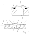
- Fig. 1 shows in cross section a microfluidic structure for metering or manipulating a liquid.
- the microfluidic structure is formed by a substrate (1) having an aperture or opening (8) in the form of a bore.
- a film (2) is at least partially or partially attached.
- the film is bulged above the planar substrate surface so that the unfastened film portions form a chamber (6), in particular a channel (5), above the flat substrate plane (21).
- the film sections close the chamber (6) preferably liquid-tight against the environment.
- opening (8) in the substrate which is in particular an inlet opening for a microfluidic network
- channel sections (5, 20) or chambers (6) as well as valve spaces in the substrate can also be delimited by the foil, as the following explanations show.
- microfluidic chambers (6) and channels (5) are advantageously formed over an unstructured substrate surface in the film, so that a costly microstructuring of the substrate carrier (1) is eliminated.
- the substrate which consists of a thermoplastic material
- the substrate is first heated and poured off in a mold, or channel structures are introduced by imprinting the negative structure of the mold into the moldable plastic.
- an unstructured substrate plate with an at least partially planar and / or flat surface can be used.
- the flat and / or planar surface regions of the substrate plate may be arranged in a stepped or terraced manner relative to one another such that individual surface regions have different heights relative to an average surface height.
- a film is attached, in particular laminated.
- Fig. 11 shows a sealing or laminating method in which a flat unstructured substrate (1) made of plastic rests on a support plate (31), which forms the counter bearing for the lamination process.
- a film (2) of thermoplastic material is placed on the substrate and pressed by means of a heatable press ram (31) with a pressure P.
- the substrate material preferably consists of pure polyolefins or of blends of polyolefins, in particular of polyethylene, polypropylene or of blends thereof with copolymers of ethylene or propylene.
- the film material is preferably a thermoplastic elastomer (TPE) based on styrene / ethylene / butylene polymers, EPR (synthetic rubber based on ethylene, polypropylene), EPDM (terpolymer based on ethylene propylene diene monomers), alloys of polyamide ( PA) with polyolefins, blends of PP / EPR / PE, PP / EPDM or PE / EVA / EPDM, EAA or polypropylene copolymers.
- TPE thermoplastic elastomer
- EPR synthetic rubber based on ethylene, polypropylene
- EPDM terpolymer based on ethylene propylene diene monomers
- PA alloys of polyamide
- PTFE films or PTFE blends or PTFE with fillers such as bronze, glass or carbon as a film material are conceivable, if a slightly wettable plastic is to be used.
- the pressing punch (31) has an opening, whereby no pressing pressure P is applied to the foil lying on the substrate in the region of the opening.
- the press ram (31) is placed in the heated state and melts the film material and / or the substrate material, melt being understood to mean that the material does not become completely liquid, but reaches a viscosity which can flow under pressure, or is plastically deformable under pressure is.
- the lamination that is the interfolding and cross-linking of the materials, is dependent on both the pressure and the laminating temperatures, these parameters can vary within a wide range.
- the geometry of the pressing surface of the press ram, the sealing pressure, the sealing temperature and the sealing time are therefore to be selected so that a desired strength and adhesion of the film (2) on the substrate (1) is achieved.
- bond strengths of 2-5 N / 10mm for easily demoldable or 5-20 N / 10mm for better adhering joints are set by the lamination.
- adhesion values of 20-80 N / 10mm are used, whereby the stated adhesion values are based on a tensile test with a 10 mm wide test piece. Values of 0.2-20 N / mm 2 are used as pressing pressure P at sealing temperatures of 70 ° C to 170 ° C. The sealing times are from 0.2 seconds to 200 seconds.
- the substrate material has a higher melting temperature and / or glass transition temperature than the film material. In the lamination in the selected temperature range, this results in a greater softening of the film material, whereby the film material is flowable than the substrate under the laminating conditions.
- the punch (31) exerts a pressure P on the film (2) and the substrate (1), in particular the film material flows due to the lower shear viscosity. Due to the pressure and the shear, in particular foil material is displaced into the areas of the punch (31) which are free of pressing pressure and thereby builds up a material wedge (11) in the edge region of the recess in the punch. In the region of the recess in the punch (31), preferably no connection of foil (2) and substrate (1) takes place, so that there arises an unsecured region (25). As a result of the material flow, the film bulges in the unsecured area and forms fluid-conducting microstructures between the substrate and the film. These can be channels (5) as in Fig. 11 , or chambers (6) or microvalves.
- the forming material wedge (11) presses the film higher in the unsecured area and supports the film structure.
- foil chambers (6) can be arranged in the substrate (1) via bores (8) or passage openings (8). Since the film is elastic, it can be easily deformed, whereby the flow of flow in substrate channels (5) or through passage openings (8) between the substrate top and substrate bottom can be controlled. As Fig. 1 can be removed, the film chamber (6) by the lamination-mounted area (24) sealed fluid-tight from the environment.
- the shape of the film chamber (5) or the film channel (5) is dependent on the laminating conditions of the film material such as pressure, lamination time and temperature as well as on the geometry of the press ram (31).
- Fig. 12 shows a lamination process in which a ram (31) is used with different sized openings. Both in the region of the smaller right-hand opening and in the region of the larger recess located in the middle in the press ram (31), the film 2 buckles and material wedges (11) are formed.
- the bulge leads to a wave-like cross-section of the film (2) in relation to the substrate (1), whereby two channels (5) form.
- a wave structure can be used in the region of a passage opening (8), since the middle zone of the film (2) projects into a passage opening (8), as in FIG Fig. 12 shown. This ensures that the capillary stop formed by the opening (8) is overcome by wetting of the film in the sagging central region.
- the press ram (31) has a semicircular recess on the contact surface.
- the film (2) bulges until it rests against the surface of the recess, thereby taking over the semicircular shape, such as FIG. 13 represents.
- a particularly strong shift of film material occurs in films with a sealing layer.
- such a film (2) consists of a cover sheet (3) and a sealing film (4).
- the sealing film is preferably made of EVA and has a lower melting point than the cover sheet (3) and as the substrate (1).
- a pressure P Upon heating and application of a pressure P, the material of the sealing film with the lowest shear viscosity at the selected laminating temperature is predominantly displaced into the unsecured region (25) and forms wedges (11).
- the amount of material displaced, the thickness of the bulge and the size of the material wedge depend on the parameters lamination time, pressing pressure and temperature.
- the Figures 2 . 14 a and 14 b show the lamination process or sealing process for producing a fluid channel after different sealing times at a constant temperature. After a first sealing time t1, the film structure of sealing film (4) and cover film (3) has in the semicircular recess after Fig. 14a arched in and fills this partially.
- material of the sealing film (4) was accumulated in a wedge shape (11) and lifts the film from the substrate surface.
- FIG. 14b in comparison to Figure 14a represents, the material thickness of the sealing film (4) decreases with increasing the sealing time. After a comparatively longer sealing time t2, the thickness of the sealing film (4) has markedly decreased, the material having flowed into the semicircular cavity in the ram (31), which the cover film (3) now completely fills.
- the initially semicircular channel (5) which is delimited on its sides by the sealing material at least in the side region and in the bottom region, is in accordance with the sealing duration t2 Fig. 14b now approximately circular.
- the size of the wedge significantly affects the capillary force in the edge region of the channel structure (5).
- an opening angle between substrate (1) and the wall of the channel (5) of 1 ° to 10 ° surrounds at 5 ° opening angle and an approximately triangular opening cross-section a center height, apex height of about 10 microns at a 250 micron wide channel (5 ).
- the gap height In an edge region of 10 ⁇ m width, in the absence of a wedge (11), the gap height would be less than 1 ⁇ m. Such an edge gap would have a strong capillary action due to the low height and would form preshooters, ie leading capillary fronts.
- these highly capillary edge areas are advantageously filled in a targeted manner, whereby unwanted pre-shooter effects can be avoided.
- the opening angle and the height of the apex (13) as in Fig. 1 represented the capillary properties of the film chambers (6) and film channels (5) can be set specifically during production.
- the shape of the film chambers (6) can be influenced both by the geometry of the recesses in the punch (31) and by vents in the punch (31) in the region of the recesses.
- a back pressure can be placed in the example, from the outside, a pneumatic pressure is introduced into the manufacturing device.
- a targeted speed of the bulge process is adjustable.
- a microfluidic device is shown, which is covered on both the substrate top side and on the underside of the substrate by a film.
- channels (5) are introduced on the top and bottom, which are fluidly connected to each other by a transverse bore (8).
- a liquid which passes through the lower channel and rises in the transverse bore (8), forms at the upper end of the transverse bore a meniscus (9), which projects into the foil chamber (6).
- the film bulged over the interior of the chamber initially has no contact with the meniscus of the liquid. Therefore, the edge of the bore (8) acts as a capillary stop for the rising in the bore (8) liquid.
- the capillary stop can be overcome by moving the film. As a result, a liquid can be metered in a targeted manner.
- the arched foil (2) is pressed down by an actuator (10) in the form of a punch or piston in the area of the passage opening (8) until wetting from the meniscus (9) to the foil wall takes place. If the actuator (10) is completely depressed, it can also terminate a metering process in a targeted manner, in that then the pressed-down film (2) seals the bore (8) along the substrate top side and along the step.
- the actuated foil chamber (6) can implement various functions, namely a valve function by opening and / or closing the chamber (6) by the actuator (10) and a throttle function by partial closing.
- a pumping function can be achieved by deliberate closing and opening.
- an actuator is also conceivable to use the shape memory properties of certain plastic film materials such as polyethylene or polyamide for moving the chamber walls or channel walls.
- plastic material is heated in the production over a certain activation temperature, which takes place through the lamination process.
- the resulting mold for example one of the previously named forms, is frozen by rapid cooling. If the material is later heated again above the activation temperature, it assumes its original form again.
- a semicircular curved film wall then loses, for example, the dome shape and closes by forming a transverse bore (8) Fig. 3 , An adjustment of the chamber wall to overcome a capillary stop can be realized by the deformation.
- Heating can be done locally by means of a thermode, by a flat heat stamp or by one or more heat radiators. Since such materials are also available for activation temperatures in the range below 50 ° C, in particular 20 ° C - 40 ° C and a heat activation by the sample material is conceivable.
- the device is cooled to a temperature below the activation temperature, for example to 25 ° C, the Akivitationstemperatur is for example 30 ° C.
- the sample liquid is introduced at a temperature above the activation temperature, for example 35 ° C, thereby independently activating a deformation of the foil walls, whereby microfluidic capillary stops and valves are opened and closed.
- a possible capillary stop on a transverse bore (8) after FIG. 4 can also be overcome passively.
- the Kammerapex (13) and the chamber wall is prepared and dreidimesional shaped that above the edge of the transverse bore (8) a capillary gap of 1 micron to 20 microns, in particular from 3 microns to 10 microns remains.
- the liquid flowing up in the transverse bore (8) forms a meniscus (9) which bridges such a capillary gap and thereby passively closes the capillary stop.
- the film chamber (6) is arranged to the edge of the step so that high capillary forces of the edge regions of the chamber are exploited to form a capillary.
- the transition region can also be provided with a hydrophilic coating in order to promote wetting.
- the production method according to the invention is particularly suitable for producing fluid channels (5) over the substrate, the width of which is a multiple of the channel height.
- the channel width is at least 5 times the channel height, in particular 10 to 50 times the channel height.
- This microfluidic channel (5) has a height of preferably 10 micrometers in a central area A (13), a height of 5 micrometers to 10 micrometers adjoining area B, and a height of 2 to 5 micrometers in the edge area C. Due to the small vertical extent of the film channel (5) this can serve to separate Blutbestend former. When flowing through the channel, larger blood particles such as erythrocytes preferentially settle in the region A, middle particles such as platelets preferentially in the region B and small blood plasma constituents preferentially in the region C.
- a sorting, separation or filtering of the blood components can take place.
- a defined location of the film (2) is not connected to the substrate and this area is fluidically connected to a microfluidic system, the construction can be used as a microfluidic valve.
- certain pressure-volume flow conditions can be set.
- a fluidic capacity and a reservoir can be deliberately introduced into the system.
- an elastic film (2) has been bonded to a substrate (1) along the substrate plane (21).
- the elastic film (2) rests on the substrate after bonding in a non-fixed area (25). If a liquid is introduced at a certain pressure, the film (2) is stretched in the region (25) so that two channel ends (20) in the substrate are fluidically connected.
- valve By applying compressed air (30), an additional restoring force acts on the foil.
- compressed air By means of compressed air, the valve can be opened and closed.
- a curved chamber (6) which connects the ends of the channels (5) fluidly with each other. Also in this embodiment can be performed by compressed air or a punch opening and closing of the chamber.
- the microfluidic device is clamped at support points (23) and bent as indicated by the arrow.
- the film (2) is lifted off the unattached surface (25) either upwards and then releases a fluid flow and / or, upon bending down, it is stretched onto the unsecured region (25).
- a valve, pump or throttling function can be implemented.
- a recess in the substrate is provided for locating and amplifying the bend. This is arranged at a location at which maximum bending radii are to be achieved, namely preferably below the microfluidic control element.
- liquids or powders are an important issue in lab-on-chip applications. It is often advantageous if the liquid or powder can be packaged and stored separately from the chip. If necessary, the container can then be applied to the chip. The problem, however, is usually the fluidic coupling of the container to the fluidic system of the chip.
- a container or blister (28) is sealed with a diffusion-tight film after filling of the container with a liquid or suspension has taken place.
- the liquid may in particular be an analyte.
- a self-adhesive and / or self-sealing layer or film is applied on the closure film of the container (28) .
- the container can be stored.
- this is inserted into a recess (22) in the substrate (1), wherein the adhesive layer (29) enters into a sealing connection to the substrate.
- the container is opened by eg needles (34).
- the self-adhesive layer contacts the chip and seals it against the openings in the chip and container.
- On top of the device channels (5) are introduced into the substrate.
- the needles (34) are hollow needles, which are fixed in holes (8) of the substrate, in particular glued. Alternatively, the needles (34) can be injection-molded or injected during the injection molding process or molding process of the substrate carrier (1).
- a channel (5) is fluidically connected to a channel (5) via an opening (8) in the film (2).
- the opening (8) is covered by a hydrophobic ventilation, a hydrophobic valve, which is permeable to gases and almost impermeable to aqueous liquids.
- the film (2) is fully attached to the substrate, with unsecured areas at the needle opening and at the channel ends. The film lies on the unpaved areas sealing.
- compressed air (30) bulges, as in Fig. 8 indicated by dashed lines, the film.
- the compressed air flows via a first hollow needle (34) into the container and displaces the analyte through a second hollow needle (34) into the channel (5).
- a substrate (1) having a stepped thickness has a greater thickness in a first region.
- an inlet (35) and the outlet (36) and an outlet are arranged, the inlet (35) and the outlet (36) may be connected to other not shown fluidic structures of a microfluidic network.
- From the inlet (35) and outlet (36) branch off channels (5) which extend in the substrate and are covered by a film (2).
- the thickness of the substrate is significantly reduced as the cross section after Fig. 9 shows.
- film channels (5) are formed in the second region, which lift off above the substrate plane which is planned there.
- the thickness-reduced substrate (1) rests on a support body (26), in particular an anvil. With an actuator (10) attached to the end of the substrate, this substrate area can be bent. By bending the film channel (5) as Fig. 10 is stretched, whereby the volume flow in the film channel (5) is throttled.
Landscapes
- Engineering & Computer Science (AREA)
- Mechanical Engineering (AREA)
- Chemical & Material Sciences (AREA)
- Health & Medical Sciences (AREA)
- General Engineering & Computer Science (AREA)
- Dispersion Chemistry (AREA)
- Hematology (AREA)
- General Health & Medical Sciences (AREA)
- Analytical Chemistry (AREA)
- Clinical Laboratory Science (AREA)
- Chemical Kinetics & Catalysis (AREA)
- Automatic Analysis And Handling Materials Therefor (AREA)
- Physical Or Chemical Processes And Apparatus (AREA)
- Micromachines (AREA)
- Investigating Or Analyzing Non-Biological Materials By The Use Of Chemical Means (AREA)
- Laminated Bodies (AREA)
Priority Applications (19)
| Application Number | Priority Date | Filing Date | Title |
|---|---|---|---|
| EP20080010082 EP2138233B1 (de) | 2008-06-02 | 2008-06-02 | Mikrofluidische Folienstruktur zum Dosierren von Flüssigkeiten |
| ES08010082T ES2352581T3 (es) | 2008-06-02 | 2008-06-02 | Estructura de lámina microfluídica para dosificar líquidos. |
| DE200850001596 DE502008001596D1 (de) | 2008-06-02 | 2008-06-02 | Mikrofluidische Folienstruktur zum Dosierren von Flüssigkeiten |
| DK08010082T DK2138233T3 (da) | 2008-06-02 | 2008-06-02 | Mikrofluid foliestruktur til dosering af væsker |
| AT08010082T ATE485101T1 (de) | 2008-06-02 | 2008-06-02 | Mikrofluidische folienstruktur zum dosierren von flüssigkeiten |
| CA2726219A CA2726219C (en) | 2008-06-02 | 2009-06-02 | Microfluidic foil structure for metering of fluids |
| KR1020107029790A KR101566182B1 (ko) | 2008-06-02 | 2009-06-02 | 유체의 계량을 위한 마이크로유체 포일 구조체 |
| BRPI0913340-2A BRPI0913340B1 (pt) | 2008-06-02 | 2009-06-02 | Estrutura microfluida, e método para sua produção |
| JP2011510902A JP5436550B2 (ja) | 2008-06-02 | 2009-06-02 | 流体計量のためのマイクロフルイディック箔構造体 |
| US12/995,550 US8580209B2 (en) | 2008-06-02 | 2009-06-02 | Microfluidic foil structure for metering of fluids |
| RU2010154517/05A RU2515287C2 (ru) | 2008-06-02 | 2009-06-02 | Микрофлюидаоьная тонкопленочная структура для дозирования текучих сред |
| MX2010013204A MX2010013204A (es) | 2008-06-02 | 2009-06-02 | Estructura de hoja de microfluido para la medicion de fluidos. |
| AU2009262555A AU2009262555B2 (en) | 2008-06-02 | 2009-06-02 | Microfluidic foil structure for metering of fluids |
| CN200980130360.0A CN102112229B (zh) | 2008-06-02 | 2009-06-02 | 用于定量供应流体的微流体箔结构 |
| NZ589466A NZ589466A (en) | 2008-06-02 | 2009-06-02 | Microfluidic foil structure for metering of fluids |
| PCT/EP2009/003908 WO2009156045A2 (en) | 2008-06-02 | 2009-06-02 | Microfluidic foil structure for metering of fluids |
| IL209405A IL209405A (en) | 2008-06-02 | 2010-11-18 | Microfluidic Foil Structure for Liquid Measurement |
| ZA2010/08267A ZA201008267B (en) | 2008-06-02 | 2010-11-18 | Microfluidic foil structure for metering of fluids |
| CL2010001328A CL2010001328A1 (es) | 2008-06-02 | 2010-12-01 | Una estructura de microfluido que comprende un sustrato y una pelicula fijada plana al sustrato con unas porciones sin fijar formando una camara o un canal, donde en la zona de borde entre las porciones sin fijar y fijadas se forma una cuña de material; metodo para producir una estructura. |
Applications Claiming Priority (1)
| Application Number | Priority Date | Filing Date | Title |
|---|---|---|---|
| EP20080010082 EP2138233B1 (de) | 2008-06-02 | 2008-06-02 | Mikrofluidische Folienstruktur zum Dosierren von Flüssigkeiten |
Publications (2)
| Publication Number | Publication Date |
|---|---|
| EP2138233A1 EP2138233A1 (de) | 2009-12-30 |
| EP2138233B1 true EP2138233B1 (de) | 2010-10-20 |
Family
ID=39884358
Family Applications (1)
| Application Number | Title | Priority Date | Filing Date |
|---|---|---|---|
| EP20080010082 Active EP2138233B1 (de) | 2008-06-02 | 2008-06-02 | Mikrofluidische Folienstruktur zum Dosierren von Flüssigkeiten |
Country Status (19)
| Country | Link |
|---|---|
| US (1) | US8580209B2 (da) |
| EP (1) | EP2138233B1 (da) |
| JP (1) | JP5436550B2 (da) |
| KR (1) | KR101566182B1 (da) |
| CN (1) | CN102112229B (da) |
| AT (1) | ATE485101T1 (da) |
| AU (1) | AU2009262555B2 (da) |
| BR (1) | BRPI0913340B1 (da) |
| CA (1) | CA2726219C (da) |
| CL (1) | CL2010001328A1 (da) |
| DE (1) | DE502008001596D1 (da) |
| DK (1) | DK2138233T3 (da) |
| ES (1) | ES2352581T3 (da) |
| IL (1) | IL209405A (da) |
| MX (1) | MX2010013204A (da) |
| NZ (1) | NZ589466A (da) |
| RU (1) | RU2515287C2 (da) |
| WO (1) | WO2009156045A2 (da) |
| ZA (1) | ZA201008267B (da) |
Families Citing this family (60)
| Publication number | Priority date | Publication date | Assignee | Title |
|---|---|---|---|---|
| JP5582049B2 (ja) * | 2010-05-31 | 2014-09-03 | 横河電機株式会社 | 化学処理用カートリッジシステム |
| US20110312537A1 (en) * | 2010-06-17 | 2011-12-22 | Geneasys Pty Ltd | Loc device for amplifying and detecting target nucleic acid sequences using electrochemiluminescent resonant energy transfer, linear probes with covalently attached primers |
| WO2012004423A1 (es) * | 2010-07-07 | 2012-01-12 | Ikerlan, S.Coop | Método de fabricación de dispositivos microfluidicos. |
| US9522520B2 (en) * | 2010-09-01 | 2016-12-20 | Boehringer Ingelheim Microparts Gmbh | Process for producing a microfluidic apparatus and related laminating devices |
| EP2637948B1 (de) * | 2010-11-10 | 2015-09-16 | Boehringer Ingelheim Microparts GmbH | Verfahren zum zuführen von flüssigkeit zu einer fluidischen anordnung |
| DE102010061909A1 (de) * | 2010-11-24 | 2012-05-24 | Fraunhofer-Gesellschaft zur Förderung der angewandten Forschung e.V. | Fluidischer Aktor mit verformbarer Verschlussanordnung und langer Lagerfähigkeit |
| DE102011003856B4 (de) | 2011-02-09 | 2020-06-18 | Robert Bosch Gmbh | Mikrosystem für fluidische Anwendungen sowie Herstellungsverfahren und Benutzungsverfahren für ein Mikrosystem für fluidische Anwendungen |
| US9675135B2 (en) * | 2011-02-11 | 2017-06-13 | Code Footwear, Llc | Reconfigurable apparel manufacture and business processes |
| US9901924B2 (en) * | 2011-07-14 | 2018-02-27 | Enplas Corporation | Fluid handling device, fluid handling method, and fluid handling system |
| US20130090633A1 (en) * | 2011-10-07 | 2013-04-11 | University Of Southern California | Osmotic patch pump |
| CN103127971B (zh) * | 2011-12-02 | 2016-04-20 | 国家纳米科学中心 | 一种微流控管道及其制备方法 |
| JP6190822B2 (ja) * | 2012-01-09 | 2017-08-30 | マイクロニクス, インコーポレイテッド | マイクロ流体リアクタシステム |
| EP2626133A1 (en) * | 2012-02-10 | 2013-08-14 | Chemtrix B.V. | Micro-fluidic system |
| TWI481446B (zh) * | 2012-09-17 | 2015-04-21 | Univ Nat Taiwan | 數位微流體操控裝置及操控方法 |
| KR101402730B1 (ko) * | 2012-09-28 | 2014-06-11 | 연세대학교 산학협력단 | 미세 유체 소자, 이의 제조방법, 및 이를 포함하는 바이오 분석 플랫폼 |
| AU2013334189B2 (en) | 2012-10-24 | 2018-08-02 | Genmark Diagnostics, Inc. | Integrated multiplex target analysis |
| US20140322706A1 (en) | 2012-10-24 | 2014-10-30 | Jon Faiz Kayyem | Integrated multipelx target analysis |
| JP6363093B2 (ja) * | 2012-12-13 | 2018-07-25 | コーニンクレッカ フィリップス エヌ ヴェKoninklijke Philips N.V. | 流体ストップを備える流体システム |
| JP6351702B2 (ja) | 2013-03-15 | 2018-07-04 | ジェンマーク ダイアグノスティクス, インコーポレイテッド | 変形可能流体容器を操作するためのシステム、方法、および装置 |
| DE102013207683A1 (de) * | 2013-04-26 | 2014-11-13 | Robert Bosch Gmbh | Verfahren und Vorrichtung zum Herstellen einer mikrofluidischen Analysekartusche |
| USD881409S1 (en) | 2013-10-24 | 2020-04-14 | Genmark Diagnostics, Inc. | Biochip cartridge |
| US9498778B2 (en) | 2014-11-11 | 2016-11-22 | Genmark Diagnostics, Inc. | Instrument for processing cartridge for performing assays in a closed sample preparation and reaction system |
| AU2014352964B2 (en) * | 2013-11-22 | 2018-12-06 | Rheonix, Inc. | Channel-less pump, methods, and applications thereof |
| WO2015186454A1 (ja) * | 2014-06-05 | 2015-12-10 | 株式会社日立ハイテクノロジーズ | 生化学用試薬類保存デバイス、及び生化学用分析装置 |
| US11305236B2 (en) | 2014-06-13 | 2022-04-19 | Gattaco Inc. | Surface tension driven filtration |
| MY188120A (en) | 2014-06-13 | 2021-11-22 | Michael Ryan Mcneely | Capillary pressure re-set mechanism and applications |
| DE102014216391A1 (de) * | 2014-08-19 | 2016-02-25 | Robert Bosch Gmbh | Reagenzienvorlagerung mit definierter Entnahme |
| DE102015101425B4 (de) * | 2014-10-31 | 2018-02-01 | Fraunhofer-Gesellschaft zur Förderung der angewandten Forschung e.V. | Verfahren zur Herstellung eines Bauelements auf Basis eines strukturierbaren Substrats mit dreidimensionaler, Poren im nm-Bereich aufweisender Membranstruktur |
| US10005080B2 (en) | 2014-11-11 | 2018-06-26 | Genmark Diagnostics, Inc. | Instrument and cartridge for performing assays in a closed sample preparation and reaction system employing electrowetting fluid manipulation |
| US9598722B2 (en) | 2014-11-11 | 2017-03-21 | Genmark Diagnostics, Inc. | Cartridge for performing assays in a closed sample preparation and reaction system |
| RU2632460C1 (ru) * | 2014-12-02 | 2017-10-04 | Конинклейке Филипс Н.В. | Диспергирование и накопление магнитных частиц в микрофлюидной системе |
| NZ735303A (en) * | 2015-03-06 | 2023-06-30 | Microgem Int Plc | Method and device for preparing and extracting a biomolecule |
| US9914116B2 (en) * | 2015-09-10 | 2018-03-13 | Panasonic Intellectual Property Management Co., Ltd. | Microelement |
| EP3367105A4 (en) * | 2015-10-23 | 2019-05-15 | Japan Science and Technology Agency | NANO FLUID DEVICE AND CHEMICAL ANALYSIS DEVICE |
| FR3051195B1 (fr) * | 2016-05-11 | 2018-05-18 | Universite Grenoble Alpes | Puce de co-culture cellulaire et son procede de fabrication |
| EP3263215B1 (de) * | 2016-06-30 | 2021-04-28 | ThinXXS Microtechnology AG | Vorrichtung mit einer flusszelle mit reagenzspeicher |
| JP6981762B2 (ja) * | 2016-08-08 | 2021-12-17 | 株式会社エンプラス | 流体取扱装置および流体取扱方法 |
| CN109789411A (zh) * | 2016-10-07 | 2019-05-21 | 勃林格殷格翰维特梅迪卡有限公司 | 用于测试特别是生物样品的储物筒 |
| CN106434282B (zh) * | 2016-10-27 | 2018-12-07 | 杭州安誉科技有限公司 | 微型流体液泡挤压机构 |
| DE102017010071A1 (de) | 2016-11-02 | 2018-05-03 | Mann+Hummel Gmbh | Einheit zum Regeln oder Steuern eines Fluiddrucks |
| DE102016013010A1 (de) * | 2016-11-02 | 2018-05-03 | Mann + Hummel Gmbh | Einheit zum Regeln oder Steuern eines Fluiddrucks |
| DE102017010018A1 (de) * | 2016-11-02 | 2018-05-03 | Mann + Hummel Gmbh | Einheit zum Regeln oder Steuern eines Fluiddrucks |
| CN106949629A (zh) * | 2017-04-28 | 2017-07-14 | 陈钦诚 | 即时水流加热体的导流板结构 |
| NL2019044B1 (en) | 2017-05-11 | 2018-11-15 | Illumina Inc | Protective surface coatings for flow cells |
| US10448183B2 (en) * | 2017-07-27 | 2019-10-15 | Bose Corporation | Method of fabricating a miniature device having an acoustic diaphragm |
| JP7452927B2 (ja) * | 2018-03-02 | 2024-03-19 | ナショナル リサーチ カウンシル オブ カナダ | 高分子マイクロ流体バルブ |
| CN110240112B (zh) * | 2018-03-09 | 2022-08-19 | 中国科学院苏州纳米技术与纳米仿生研究所 | 薄膜驱动结构、薄膜驱动结构的制造方法及喷墨装置 |
| DE102018204633A1 (de) * | 2018-03-27 | 2019-10-02 | Robert Bosch Gmbh | Mikrofluidische Vorrichtung und Verfahren zum Prozessieren einer Flüssigkeit |
| CN109695747B (zh) * | 2019-01-25 | 2021-01-26 | 京东方科技集团股份有限公司 | 数字逻辑执行器、数字逻辑执行方法及喷墨打印设备 |
| JP2020138283A (ja) * | 2019-02-28 | 2020-09-03 | 株式会社エンプラス | 流体取扱装置の製造方法 |
| CN109781954B (zh) * | 2019-03-06 | 2021-07-20 | 山东清风环境检测有限公司 | 一种自动化污水水质检测仪 |
| TWI902731B (zh) | 2019-12-30 | 2025-11-01 | 美商伊路米納有限公司 | 與流動池一同使用之致動系統及設備 |
| JP7822938B2 (ja) * | 2020-01-14 | 2026-03-03 | ミダイアグノスティクス・エヌブイ | 毛細管駆動流体接続用のマイクロ流体装置 |
| EP3854868A1 (en) * | 2020-01-24 | 2021-07-28 | Nederlandse Organisatie voor toegepast- natuurwetenschappelijk Onderzoek TNO | Microfluidic device for analyzing a membrane |
| US11221285B2 (en) * | 2020-01-31 | 2022-01-11 | The Boeing Company | System and method for inspecting secondary bonds in laminated parts |
| JP2022049382A (ja) * | 2020-09-16 | 2022-03-29 | 株式会社エンプラス | 流体取扱装置および流体取扱装置の製造方法 |
| CN112452365B (zh) * | 2020-11-23 | 2021-12-07 | 无锡市夸克微智造科技有限责任公司 | 微加工流体装置 |
| US20240050940A1 (en) * | 2020-12-24 | 2024-02-15 | Fujimori Kogyo Co., Ltd. | Method for manufacturing micro chip for liquid sample analysis |
| GB202118918D0 (en) * | 2021-12-23 | 2022-02-09 | Osler Diagnostics Ltd | Liquid storage cavity |
| WO2023170153A1 (de) * | 2022-03-09 | 2023-09-14 | Hnp Mikrosysteme Gmbh | Fluidisches system und verfahren zum betreiben eines fluidischen systems |
Family Cites Families (22)
| Publication number | Priority date | Publication date | Assignee | Title |
|---|---|---|---|---|
| SU975056A1 (ru) * | 1981-03-18 | 1982-11-23 | Предприятие П/Я М-5534 | Автоматическа бюретка-дозатор |
| FI844320A7 (fi) * | 1984-11-02 | 1986-05-03 | Labsystems Oy | Utspaedningsdoseringsanordning. |
| EP0418836A3 (en) * | 1989-09-22 | 1991-11-21 | Hercules Incorporated | Multilayer oriented film containing polypropylene and co-polyester |
| TW313588B (da) * | 1992-10-23 | 1997-08-21 | Eastman Kodak Co | |
| DK24493D0 (da) | 1993-03-05 | 1993-03-05 | Novo Nordisk As | |
| WO1997010435A2 (de) * | 1995-09-15 | 1997-03-20 | Institut Für Mikro- Und Informationstechnik Hahn-Schickard-Gesellschaft | Rückschlagventillose fluidpumpe |
| US5753429A (en) * | 1996-08-09 | 1998-05-19 | Lifescan, Inc. | Analyte concentration measurement using a hollow frustum |
| US6293012B1 (en) | 1997-07-21 | 2001-09-25 | Ysi Incorporated | Method of making a fluid flow module |
| US5932799A (en) * | 1997-07-21 | 1999-08-03 | Ysi Incorporated | Microfluidic analyzer module |
| FR2795476B1 (fr) * | 1999-06-22 | 2001-07-27 | Biomerieux Sa | Vanne permettant de diriger un fluide dans une carte d'analyse |
| US6428901B1 (en) * | 1999-12-20 | 2002-08-06 | Exxonmobil Chemical Patents Inc. | Films formed from blends of polyethylene and polypropylene |
| US6734401B2 (en) * | 2000-06-28 | 2004-05-11 | 3M Innovative Properties Company | Enhanced sample processing devices, systems and methods |
| EP1331997B1 (en) * | 2000-11-06 | 2004-06-16 | Nanostream, Inc. | Microfluidic flow control devices |
| EP1350029B1 (en) * | 2001-01-08 | 2014-09-10 | President and Fellows of Harvard College | Valves and pumps for microfluidic systems and method for making microfluidic systems |
| WO2002081934A2 (en) | 2001-04-03 | 2002-10-17 | Micronics, Inc. | Pneumatic valve interface for use in microfluidic structures |
| JP3777112B2 (ja) * | 2001-11-02 | 2006-05-24 | 財団法人川村理化学研究所 | マイクロ流体デバイス及びその製造方法 |
| GB0128350D0 (en) * | 2001-11-27 | 2002-01-16 | Lab901 Ltd | Non-rigid apparatus for microfluidic applications |
| GB0303920D0 (en) * | 2003-02-21 | 2003-03-26 | Sophion Bioscience As | Capillary stop |
| US7832429B2 (en) | 2004-10-13 | 2010-11-16 | Rheonix, Inc. | Microfluidic pump and valve structures and fabrication methods |
| CN101263077B (zh) * | 2005-09-09 | 2011-11-09 | 皇家飞利浦电子股份有限公司 | 一种制造具有间隔的微系统的方法 |
| GB2445738A (en) * | 2007-01-16 | 2008-07-23 | Lab901 Ltd | Microfluidic device |
| JP2008284626A (ja) * | 2007-05-16 | 2008-11-27 | Miraial Kk | マイクロ流路デバイス |
-
2008
- 2008-06-02 DE DE200850001596 patent/DE502008001596D1/de active Active
- 2008-06-02 EP EP20080010082 patent/EP2138233B1/de active Active
- 2008-06-02 DK DK08010082T patent/DK2138233T3/da active
- 2008-06-02 AT AT08010082T patent/ATE485101T1/de active
- 2008-06-02 ES ES08010082T patent/ES2352581T3/es active Active
-
2009
- 2009-06-02 RU RU2010154517/05A patent/RU2515287C2/ru active
- 2009-06-02 BR BRPI0913340-2A patent/BRPI0913340B1/pt not_active IP Right Cessation
- 2009-06-02 KR KR1020107029790A patent/KR101566182B1/ko active Active
- 2009-06-02 MX MX2010013204A patent/MX2010013204A/es active IP Right Grant
- 2009-06-02 CN CN200980130360.0A patent/CN102112229B/zh active Active
- 2009-06-02 CA CA2726219A patent/CA2726219C/en active Active
- 2009-06-02 WO PCT/EP2009/003908 patent/WO2009156045A2/en not_active Ceased
- 2009-06-02 US US12/995,550 patent/US8580209B2/en active Active
- 2009-06-02 JP JP2011510902A patent/JP5436550B2/ja active Active
- 2009-06-02 AU AU2009262555A patent/AU2009262555B2/en not_active Ceased
- 2009-06-02 NZ NZ589466A patent/NZ589466A/xx not_active IP Right Cessation
-
2010
- 2010-11-18 ZA ZA2010/08267A patent/ZA201008267B/en unknown
- 2010-11-18 IL IL209405A patent/IL209405A/en active IP Right Grant
- 2010-12-01 CL CL2010001328A patent/CL2010001328A1/es unknown
Also Published As
| Publication number | Publication date |
|---|---|
| WO2009156045A2 (en) | 2009-12-30 |
| NZ589466A (en) | 2013-08-30 |
| BRPI0913340B1 (pt) | 2019-06-25 |
| CN102112229B (zh) | 2014-08-06 |
| CA2726219A1 (en) | 2009-12-30 |
| IL209405A (en) | 2016-07-31 |
| KR101566182B1 (ko) | 2015-11-05 |
| BRPI0913340A2 (pt) | 2015-11-24 |
| EP2138233A1 (de) | 2009-12-30 |
| WO2009156045A4 (en) | 2010-05-20 |
| RU2515287C2 (ru) | 2014-05-10 |
| CN102112229A (zh) | 2011-06-29 |
| JP5436550B2 (ja) | 2014-03-05 |
| CL2010001328A1 (es) | 2011-06-10 |
| DE502008001596D1 (de) | 2010-12-02 |
| KR20110021999A (ko) | 2011-03-04 |
| US8580209B2 (en) | 2013-11-12 |
| JP2011524815A (ja) | 2011-09-08 |
| DK2138233T3 (da) | 2011-01-31 |
| ATE485101T1 (de) | 2010-11-15 |
| WO2009156045A3 (en) | 2010-03-18 |
| RU2010154517A (ru) | 2012-07-20 |
| AU2009262555B2 (en) | 2015-05-07 |
| ES2352581T3 (es) | 2011-02-21 |
| IL209405A0 (en) | 2011-01-31 |
| AU2009262555A1 (en) | 2009-12-30 |
| MX2010013204A (es) | 2011-02-25 |
| US20110135546A1 (en) | 2011-06-09 |
| ZA201008267B (en) | 2011-07-27 |
| CA2726219C (en) | 2016-03-15 |
Similar Documents
| Publication | Publication Date | Title |
|---|---|---|
| EP2138233B1 (de) | Mikrofluidische Folienstruktur zum Dosierren von Flüssigkeiten | |
| EP2099567B1 (de) | Vorrichtung zur aufnahme oder manipulation einer flüssigkeit | |
| EP2576065B1 (de) | Flusszelle mit hohlraum und diaphragma | |
| EP2783752B1 (de) | Normal-geschlossenes Ventil für mikrofluidische Bauteile aus einem polymeren Schichtsystem sowie Verfahren | |
| EP2611594B1 (de) | Verfahren zum herstellen einer mikrofluidischen vorrichtung sowie diesbezügliche laminiereinrichtungen | |
| EP3393661B1 (de) | Mikrofluidische vorrichtung und verfahren zum betreiben einer mikrofluidischen vorrichtung | |
| EP2686595B1 (de) | Mikrofluidisches ventil und mikrofluidische plattform | |
| EP3049186B1 (de) | Analyseeinheit zum durchführen einer polymerasekettenreaktion, verfahren zum betreiben einer solchen analyseeinheit und verfahren zum herstellen einer solchen analyseeinheit | |
| EP2647435B1 (de) | Anordnung aus einer flusszelle und einem temperierelement | |
| EP2286126A1 (de) | Quetschventil und verfahren zu dessen herstellung | |
| EP2905079A1 (de) | Vorrichtung zum Vorlagern eines Fluids in einem mikrofluidischen System, Verfahren zum Betreiben und Verfahren zum Herstellen einer solchen Vorrichtung | |
| DE102011079698A1 (de) | Mikrofluidische Vorrichtung mit einer Kammer zur Lagerung einer Flüssigkeit | |
| WO2010031559A1 (de) | Mikrofluidisches ventil, mikrofluidische pumpe, mikrofluidisches system und ein herstellungsverfahren | |
| DE102014202342A1 (de) | Vorrichtung zum Vorlagern eines Fluids in einem mikrofluidischen System, Verfahren zum Betreiben und Verfahren zum Herstellen einer solchen Vorrichtung | |
| DE202014104510U1 (de) | Vorrichtung zum Vorlagern eines Fluids in einem mikrofluidischen System | |
| EP2759751A2 (de) | Verfahren zum Herstellen eines normal-geschlossenen Rückschlagventils für mikrofluidische Bauteile aus einem polymeren Schichtsystem und Rückschlagventil | |
| DE10335492B4 (de) | Verfahren zum selektiven Verbinden von mikrostrukturierten Teilen | |
| DE102012221835B3 (de) | Normal-geschlossenes Rückschlagventil für mikrofluidische Bauteile aus einem polymeren Schichtsystem und Verfahren zum Herstellen des Rückschlagventils |
Legal Events
| Date | Code | Title | Description |
|---|---|---|---|
| PUAI | Public reference made under article 153(3) epc to a published international application that has entered the european phase |
Free format text: ORIGINAL CODE: 0009012 |
|
| 17P | Request for examination filed |
Effective date: 20080610 |
|
| AK | Designated contracting states |
Kind code of ref document: A1 Designated state(s): AT BE BG CH CY CZ DE DK EE ES FI FR GB GR HR HU IE IS IT LI LT LU LV MC MT NL NO PL PT RO SE SI SK TR |
|
| AX | Request for extension of the european patent |
Extension state: AL BA MK RS |
|
| GRAP | Despatch of communication of intention to grant a patent |
Free format text: ORIGINAL CODE: EPIDOSNIGR1 |
|
| GRAS | Grant fee paid |
Free format text: ORIGINAL CODE: EPIDOSNIGR3 |
|
| AKX | Designation fees paid |
Designated state(s): AT BE BG CH CY CZ DE DK EE ES FI FR GB GR HR HU IE IS IT LI LT LU LV MC MT NL NO PL PT RO SE SI SK TR |
|
| GRAA | (expected) grant |
Free format text: ORIGINAL CODE: 0009210 |
|
| AK | Designated contracting states |
Kind code of ref document: B1 Designated state(s): AT BE BG CH CY CZ DE DK EE ES FI FR GB GR HR HU IE IS IT LI LT LU LV MC MT NL NO PL PT RO SE SI SK TR |
|
| REG | Reference to a national code |
Ref country code: GB Ref legal event code: FG4D Free format text: NOT ENGLISH |
|
| REG | Reference to a national code |
Ref country code: CH Ref legal event code: EP |
|
| REG | Reference to a national code |
Ref country code: IE Ref legal event code: FG4D Free format text: LANGUAGE OF EP DOCUMENT: GERMAN |
|
| REF | Corresponds to: |
Ref document number: 502008001596 Country of ref document: DE Date of ref document: 20101202 Kind code of ref document: P |
|
| REG | Reference to a national code |
Ref country code: DK Ref legal event code: T3 |
|
| REG | Reference to a national code |
Ref country code: SE Ref legal event code: TRGR |
|
| REG | Reference to a national code |
Ref country code: NL Ref legal event code: T3 |
|
| REG | Reference to a national code |
Ref country code: ES Ref legal event code: FG2A Effective date: 20110209 |
|
| LTIE | Lt: invalidation of european patent or patent extension |
Effective date: 20101020 |
|
| PG25 | Lapsed in a contracting state [announced via postgrant information from national office to epo] |
Ref country code: LT Free format text: LAPSE BECAUSE OF FAILURE TO SUBMIT A TRANSLATION OF THE DESCRIPTION OR TO PAY THE FEE WITHIN THE PRESCRIBED TIME-LIMIT Effective date: 20101020 Ref country code: NO Free format text: LAPSE BECAUSE OF FAILURE TO SUBMIT A TRANSLATION OF THE DESCRIPTION OR TO PAY THE FEE WITHIN THE PRESCRIBED TIME-LIMIT Effective date: 20110120 |
|
| REG | Reference to a national code |
Ref country code: IE Ref legal event code: FD4D |
|
| PG25 | Lapsed in a contracting state [announced via postgrant information from national office to epo] |
Ref country code: BG Free format text: LAPSE BECAUSE OF FAILURE TO SUBMIT A TRANSLATION OF THE DESCRIPTION OR TO PAY THE FEE WITHIN THE PRESCRIBED TIME-LIMIT Effective date: 20110120 Ref country code: SI Free format text: LAPSE BECAUSE OF FAILURE TO SUBMIT A TRANSLATION OF THE DESCRIPTION OR TO PAY THE FEE WITHIN THE PRESCRIBED TIME-LIMIT Effective date: 20101020 Ref country code: IS Free format text: LAPSE BECAUSE OF FAILURE TO SUBMIT A TRANSLATION OF THE DESCRIPTION OR TO PAY THE FEE WITHIN THE PRESCRIBED TIME-LIMIT Effective date: 20110220 Ref country code: FI Free format text: LAPSE BECAUSE OF FAILURE TO SUBMIT A TRANSLATION OF THE DESCRIPTION OR TO PAY THE FEE WITHIN THE PRESCRIBED TIME-LIMIT Effective date: 20101020 Ref country code: LV Free format text: LAPSE BECAUSE OF FAILURE TO SUBMIT A TRANSLATION OF THE DESCRIPTION OR TO PAY THE FEE WITHIN THE PRESCRIBED TIME-LIMIT Effective date: 20101020 Ref country code: HR Free format text: LAPSE BECAUSE OF FAILURE TO SUBMIT A TRANSLATION OF THE DESCRIPTION OR TO PAY THE FEE WITHIN THE PRESCRIBED TIME-LIMIT Effective date: 20101020 Ref country code: PT Free format text: LAPSE BECAUSE OF FAILURE TO SUBMIT A TRANSLATION OF THE DESCRIPTION OR TO PAY THE FEE WITHIN THE PRESCRIBED TIME-LIMIT Effective date: 20110221 |
|
| REG | Reference to a national code |
Ref country code: HU Ref legal event code: AG4A Ref document number: E010270 Country of ref document: HU |
|
| PG25 | Lapsed in a contracting state [announced via postgrant information from national office to epo] |
Ref country code: GR Free format text: LAPSE BECAUSE OF FAILURE TO SUBMIT A TRANSLATION OF THE DESCRIPTION OR TO PAY THE FEE WITHIN THE PRESCRIBED TIME-LIMIT Effective date: 20110121 |
|
| PG25 | Lapsed in a contracting state [announced via postgrant information from national office to epo] |
Ref country code: CZ Free format text: LAPSE BECAUSE OF FAILURE TO SUBMIT A TRANSLATION OF THE DESCRIPTION OR TO PAY THE FEE WITHIN THE PRESCRIBED TIME-LIMIT Effective date: 20101020 Ref country code: IE Free format text: LAPSE BECAUSE OF FAILURE TO SUBMIT A TRANSLATION OF THE DESCRIPTION OR TO PAY THE FEE WITHIN THE PRESCRIBED TIME-LIMIT Effective date: 20101020 Ref country code: EE Free format text: LAPSE BECAUSE OF FAILURE TO SUBMIT A TRANSLATION OF THE DESCRIPTION OR TO PAY THE FEE WITHIN THE PRESCRIBED TIME-LIMIT Effective date: 20101020 |
|
| PLBE | No opposition filed within time limit |
Free format text: ORIGINAL CODE: 0009261 |
|
| STAA | Information on the status of an ep patent application or granted ep patent |
Free format text: STATUS: NO OPPOSITION FILED WITHIN TIME LIMIT |
|
| PG25 | Lapsed in a contracting state [announced via postgrant information from national office to epo] |
Ref country code: SK Free format text: LAPSE BECAUSE OF FAILURE TO SUBMIT A TRANSLATION OF THE DESCRIPTION OR TO PAY THE FEE WITHIN THE PRESCRIBED TIME-LIMIT Effective date: 20101020 Ref country code: PL Free format text: LAPSE BECAUSE OF FAILURE TO SUBMIT A TRANSLATION OF THE DESCRIPTION OR TO PAY THE FEE WITHIN THE PRESCRIBED TIME-LIMIT Effective date: 20101020 Ref country code: RO Free format text: LAPSE BECAUSE OF FAILURE TO SUBMIT A TRANSLATION OF THE DESCRIPTION OR TO PAY THE FEE WITHIN THE PRESCRIBED TIME-LIMIT Effective date: 20101020 |
|
| 26N | No opposition filed |
Effective date: 20110721 |
|
| REG | Reference to a national code |
Ref country code: DE Ref legal event code: R097 Ref document number: 502008001596 Country of ref document: DE Effective date: 20110721 |
|
| PG25 | Lapsed in a contracting state [announced via postgrant information from national office to epo] |
Ref country code: MT Free format text: LAPSE BECAUSE OF FAILURE TO SUBMIT A TRANSLATION OF THE DESCRIPTION OR TO PAY THE FEE WITHIN THE PRESCRIBED TIME-LIMIT Effective date: 20101020 |
|
| PG25 | Lapsed in a contracting state [announced via postgrant information from national office to epo] |
Ref country code: MC Free format text: LAPSE BECAUSE OF NON-PAYMENT OF DUE FEES Effective date: 20110630 |
|
| PG25 | Lapsed in a contracting state [announced via postgrant information from national office to epo] |
Ref country code: LU Free format text: LAPSE BECAUSE OF NON-PAYMENT OF DUE FEES Effective date: 20110602 Ref country code: CY Free format text: LAPSE BECAUSE OF EXPIRATION OF PROTECTION Effective date: 20101020 |
|
| REG | Reference to a national code |
Ref country code: FR Ref legal event code: PLFP Year of fee payment: 8 |
|
| REG | Reference to a national code |
Ref country code: FR Ref legal event code: PLFP Year of fee payment: 9 |
|
| REG | Reference to a national code |
Ref country code: FR Ref legal event code: PLFP Year of fee payment: 10 |
|
| REG | Reference to a national code |
Ref country code: FR Ref legal event code: PLFP Year of fee payment: 11 |
|
| PGFP | Annual fee paid to national office [announced via postgrant information from national office to epo] |
Ref country code: DK Payment date: 20240621 Year of fee payment: 17 |
|
| PGFP | Annual fee paid to national office [announced via postgrant information from national office to epo] |
Ref country code: AT Payment date: 20240620 Year of fee payment: 17 |
|
| PGFP | Annual fee paid to national office [announced via postgrant information from national office to epo] |
Ref country code: TR Payment date: 20240524 Year of fee payment: 17 Ref country code: SE Payment date: 20240619 Year of fee payment: 17 Ref country code: HU Payment date: 20240621 Year of fee payment: 17 Ref country code: BE Payment date: 20240619 Year of fee payment: 17 |
|
| PGFP | Annual fee paid to national office [announced via postgrant information from national office to epo] |
Ref country code: IT Payment date: 20240625 Year of fee payment: 17 |
|
| PGFP | Annual fee paid to national office [announced via postgrant information from national office to epo] |
Ref country code: CH Payment date: 20240701 Year of fee payment: 17 Ref country code: ES Payment date: 20240726 Year of fee payment: 17 |
|
| PGFP | Annual fee paid to national office [announced via postgrant information from national office to epo] |
Ref country code: DE Payment date: 20250618 Year of fee payment: 18 |
|
| PGFP | Annual fee paid to national office [announced via postgrant information from national office to epo] |
Ref country code: GB Payment date: 20250618 Year of fee payment: 18 |
|
| PGFP | Annual fee paid to national office [announced via postgrant information from national office to epo] |
Ref country code: NL Payment date: 20250618 Year of fee payment: 18 |
|
| PGFP | Annual fee paid to national office [announced via postgrant information from national office to epo] |
Ref country code: FR Payment date: 20250624 Year of fee payment: 18 |
|
| REG | Reference to a national code |
Ref country code: CH Ref legal event code: H13 Free format text: ST27 STATUS EVENT CODE: U-0-0-H10-H13 (AS PROVIDED BY THE NATIONAL OFFICE) Effective date: 20260127 |
|
| REG | Reference to a national code |
Ref country code: DK Ref legal event code: EBP Effective date: 20250630 |
|
| REG | Reference to a national code |
Ref country code: SE Ref legal event code: EUG |
|
| REG | Reference to a national code |
Ref country code: AT Ref legal event code: MM01 Ref document number: 485101 Country of ref document: AT Kind code of ref document: T Effective date: 20250602 |
|
| PG25 | Lapsed in a contracting state [announced via postgrant information from national office to epo] |
Ref country code: HU Free format text: LAPSE BECAUSE OF NON-PAYMENT OF DUE FEES Effective date: 20250603 |
|
| REG | Reference to a national code |
Ref country code: BE Ref legal event code: MM Effective date: 20250630 |
|
| PG25 | Lapsed in a contracting state [announced via postgrant information from national office to epo] |
Ref country code: AT Free format text: LAPSE BECAUSE OF NON-PAYMENT OF DUE FEES Effective date: 20250602 |
|
| PG25 | Lapsed in a contracting state [announced via postgrant information from national office to epo] |
Ref country code: BE Free format text: LAPSE BECAUSE OF NON-PAYMENT OF DUE FEES Effective date: 20250630 Ref country code: IT Free format text: LAPSE BECAUSE OF NON-PAYMENT OF DUE FEES Effective date: 20250602 |
|
| PG25 | Lapsed in a contracting state [announced via postgrant information from national office to epo] |
Ref country code: CH Free format text: LAPSE BECAUSE OF NON-PAYMENT OF DUE FEES Effective date: 20250630 |