EP2137488B1 - Procédé et dispositif de reproduction optique à discrimination en profondeur - Google Patents
Procédé et dispositif de reproduction optique à discrimination en profondeur Download PDFInfo
- Publication number
- EP2137488B1 EP2137488B1 EP08736106A EP08736106A EP2137488B1 EP 2137488 B1 EP2137488 B1 EP 2137488B1 EP 08736106 A EP08736106 A EP 08736106A EP 08736106 A EP08736106 A EP 08736106A EP 2137488 B1 EP2137488 B1 EP 2137488B1
- Authority
- EP
- European Patent Office
- Prior art keywords
- illumination
- sample
- light
- distributions
- optical
- Prior art date
- Legal status (The legal status is an assumption and is not a legal conclusion. Google has not performed a legal analysis and makes no representation as to the accuracy of the status listed.)
- Active
Links
- 230000003287 optical effect Effects 0.000 title claims abstract description 69
- 238000000034 method Methods 0.000 title claims abstract description 52
- 238000009826 distribution Methods 0.000 claims abstract description 52
- 238000001514 detection method Methods 0.000 claims abstract description 14
- 238000005286 illumination Methods 0.000 claims description 81
- 230000003595 spectral effect Effects 0.000 claims description 13
- 238000003384 imaging method Methods 0.000 claims description 12
- 230000000295 complement effect Effects 0.000 claims description 11
- 230000010287 polarization Effects 0.000 claims description 8
- 238000004364 calculation method Methods 0.000 claims description 7
- 230000005284 excitation Effects 0.000 claims description 7
- 230000005540 biological transmission Effects 0.000 claims description 5
- 230000000737 periodic effect Effects 0.000 claims description 5
- 238000004020 luminiscence type Methods 0.000 claims description 4
- 238000012545 processing Methods 0.000 claims description 4
- 230000003993 interaction Effects 0.000 claims description 3
- 239000000203 mixture Substances 0.000 claims description 3
- 239000013307 optical fiber Substances 0.000 claims description 2
- 230000001360 synchronised effect Effects 0.000 claims description 2
- 230000002123 temporal effect Effects 0.000 claims description 2
- 238000000386 microscopy Methods 0.000 abstract description 10
- 238000005259 measurement Methods 0.000 description 13
- 230000008901 benefit Effects 0.000 description 7
- 230000008859 change Effects 0.000 description 7
- 238000001444 catalytic combustion detection Methods 0.000 description 4
- 238000010276 construction Methods 0.000 description 3
- 238000012937 correction Methods 0.000 description 3
- 238000000799 fluorescence microscopy Methods 0.000 description 3
- 230000006870 function Effects 0.000 description 3
- 238000012634 optical imaging Methods 0.000 description 3
- 230000004075 alteration Effects 0.000 description 2
- 238000004458 analytical method Methods 0.000 description 2
- 238000013459 approach Methods 0.000 description 2
- 230000010354 integration Effects 0.000 description 2
- 238000004519 manufacturing process Methods 0.000 description 2
- 239000000463 material Substances 0.000 description 2
- 230000010363 phase shift Effects 0.000 description 2
- 230000008569 process Effects 0.000 description 2
- 238000000926 separation method Methods 0.000 description 2
- 239000000758 substrate Substances 0.000 description 2
- 241000226585 Antennaria plantaginifolia Species 0.000 description 1
- 238000010521 absorption reaction Methods 0.000 description 1
- 230000006978 adaptation Effects 0.000 description 1
- 230000000712 assembly Effects 0.000 description 1
- 238000000429 assembly Methods 0.000 description 1
- 238000004061 bleaching Methods 0.000 description 1
- 238000010226 confocal imaging Methods 0.000 description 1
- 230000008878 coupling Effects 0.000 description 1
- 238000010168 coupling process Methods 0.000 description 1
- 238000005859 coupling reaction Methods 0.000 description 1
- 238000005520 cutting process Methods 0.000 description 1
- 230000001419 dependent effect Effects 0.000 description 1
- 239000003814 drug Substances 0.000 description 1
- 239000000975 dye Substances 0.000 description 1
- 230000000694 effects Effects 0.000 description 1
- 230000008030 elimination Effects 0.000 description 1
- 238000003379 elimination reaction Methods 0.000 description 1
- 238000005516 engineering process Methods 0.000 description 1
- 238000005530 etching Methods 0.000 description 1
- 238000002292 fluorescence lifetime imaging microscopy Methods 0.000 description 1
- 239000011521 glass Substances 0.000 description 1
- 238000013507 mapping Methods 0.000 description 1
- 238000005457 optimization Methods 0.000 description 1
- 230000000704 physical effect Effects 0.000 description 1
- 230000005855 radiation Effects 0.000 description 1
- 238000001454 recorded image Methods 0.000 description 1
- 230000009467 reduction Effects 0.000 description 1
- 238000002310 reflectometry Methods 0.000 description 1
- 238000012552 review Methods 0.000 description 1
- 238000004441 surface measurement Methods 0.000 description 1
- 230000009466 transformation Effects 0.000 description 1
Images


Classifications
-
- G—PHYSICS
- G01—MEASURING; TESTING
- G01B—MEASURING LENGTH, THICKNESS OR SIMILAR LINEAR DIMENSIONS; MEASURING ANGLES; MEASURING AREAS; MEASURING IRREGULARITIES OF SURFACES OR CONTOURS
- G01B11/00—Measuring arrangements characterised by the use of optical techniques
- G01B11/24—Measuring arrangements characterised by the use of optical techniques for measuring contours or curvatures
- G01B11/25—Measuring arrangements characterised by the use of optical techniques for measuring contours or curvatures by projecting a pattern, e.g. one or more lines, moiré fringes on the object
- G01B11/2504—Calibration devices
-
- G—PHYSICS
- G01—MEASURING; TESTING
- G01N—INVESTIGATING OR ANALYSING MATERIALS BY DETERMINING THEIR CHEMICAL OR PHYSICAL PROPERTIES
- G01N21/00—Investigating or analysing materials by the use of optical means, i.e. using sub-millimetre waves, infrared, visible or ultraviolet light
- G01N21/62—Systems in which the material investigated is excited whereby it emits light or causes a change in wavelength of the incident light
- G01N21/63—Systems in which the material investigated is excited whereby it emits light or causes a change in wavelength of the incident light optically excited
- G01N21/64—Fluorescence; Phosphorescence
- G01N21/645—Specially adapted constructive features of fluorimeters
- G01N21/6456—Spatial resolved fluorescence measurements; Imaging
- G01N21/6458—Fluorescence microscopy
-
- G—PHYSICS
- G02—OPTICS
- G02B—OPTICAL ELEMENTS, SYSTEMS OR APPARATUS
- G02B21/00—Microscopes
- G02B21/36—Microscopes arranged for photographic purposes or projection purposes or digital imaging or video purposes including associated control and data processing arrangements
- G02B21/365—Control or image processing arrangements for digital or video microscopes
- G02B21/367—Control or image processing arrangements for digital or video microscopes providing an output produced by processing a plurality of individual source images, e.g. image tiling, montage, composite images, depth sectioning, image comparison
-
- G—PHYSICS
- G06—COMPUTING; CALCULATING OR COUNTING
- G06T—IMAGE DATA PROCESSING OR GENERATION, IN GENERAL
- G06T7/00—Image analysis
- G06T7/50—Depth or shape recovery
- G06T7/55—Depth or shape recovery from multiple images
Definitions
- the U.S. Patent 5,381,236 [11] describes an optical sensor for determining the distance of three-dimensional objects ("range finding").
- range finding a periodic structure is projected into the object, whereby the illumination structure can be reversed, which corresponds to a phase shift of 180 degrees.
- the method proposed here is also based on the change of the projected structure in two steps, but has the following differences compared to [11]:
- the individual elements of the projected illumination structure must be exactly aligned to the individual elements of the detector (CCD pixel) in [11]. This is a severe limitation for several reasons:
- the optical assembly would need to closely follow the imaging scale to match the illumination pattern to the detector.
- the relative adjustment of the two structures would have to be realized very precisely and be sub-pixel accurate.
- Another aspect of the proposed device relates to the generation of optical slices wherein the sample is scanned at different wavelengths.
- This can lead to a problem with the axial chromatic properties of the optics, which has hitherto been e.g. was solved by a mechanical tracking of optical elements.
- arrangements are disclosed which solve the problem of axial chromatic correction in structured illumination, in particular when integrated into conventional microscope systems, without moving mechanical elements and offer further speed advantages over the prior art.
Landscapes
- Engineering & Computer Science (AREA)
- Physics & Mathematics (AREA)
- General Physics & Mathematics (AREA)
- Computer Vision & Pattern Recognition (AREA)
- Multimedia (AREA)
- Chemical & Material Sciences (AREA)
- Analytical Chemistry (AREA)
- Health & Medical Sciences (AREA)
- Theoretical Computer Science (AREA)
- Optics & Photonics (AREA)
- Nuclear Medicine, Radiotherapy & Molecular Imaging (AREA)
- Life Sciences & Earth Sciences (AREA)
- Biochemistry (AREA)
- General Health & Medical Sciences (AREA)
- Immunology (AREA)
- Pathology (AREA)
- Microscoopes, Condenser (AREA)
- Length Measuring Devices By Optical Means (AREA)
- Investigating, Analyzing Materials By Fluorescence Or Luminescence (AREA)
Abstract
Claims (9)
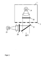
- Dispositif pour engendrer des images optiques en coupe, composé d'une unité d'éclairage (1), d'un dispositif optique (5) pour produire une image d'un échantillon sur au moins un détecteur à résolution locale (11), d'un système de focalisation, ainsi que d'une unité de traitement de signaux pour mettre en oeuvre un procédé pour produire une image optique avec discrimination en profondeur,
caractérisé en ce que
l'unité d'éclairage engendre, par éclairage d'un masque avec des sources lumineuses (19 ; 23) uniquement deux répartitions d'éclairage complémentaires respectives dans ou sur l'échantillon, les répartitions d'éclairage possèdent une périodicité dans au moins une direction dans l'espace, le plan d'échantillon dans lequel est engendrée la répartition d'éclairage est conjugué avec le plan du détecteur à résolution locale (11) respectif, et les deux répartitions de lumière qui apparaissent sous la lumière d'éclairage dans ou sur l'échantillon par interaction avec la lumière d'éclairage sont enregistrées de manière séquentielle dans le temps ou de manière parallèle dans le temps par un ou par plusieurs détecteurs (11) à résolution locale, et sont amenées à l'unité de traitement de signaux pour le calcul et la production d'une image optique en coupe S(x,y),
dans lequel au moyen d'une étape de calibrage, il est possible de déterminer la phase locale de la structure périodique σ(x,y) et la fréquence de grille locale g(x,y), et
pour le calcul de l'image en coupe S(x,y) on utilise à partir des deux répartitions d'éclairage respectivement enregistrées des différences entre les répartitions d'éclairage et/ou des différences entre des propriétés spatiales à l'intérieur des deux répartitions d'éclairage, les propriétés spatiales sont des dérivées partielles ou des gradients à l'intérieur des répartitions d'éclairage, et l'image en coupe recherchée S(x,y) est calculée en se basant sur l'équation :

dans laquelle

dans laquelle I1(x,y) et I2(x,y) sont les répartitions d'intensité complémentaires mesurées au niveau du détecteur (11). - Dispositif pour engendrer des images optiques en coupe selon la revendication 1,
caractérisé en ce que
les répartitions de lumière qui apparaissent au moyen de la lumière d'éclairage dans ou sur l'échantillon par interaction avec la lumière d'éclairage sont enregistrées de manière parallèle dans le temps par lesdits un ou plusieurs détecteurs à résolution locale (11) et sont amenées à l'unité de traitement de signaux pour le calcul et la production d'une image optique en coupe, dans lequel les deux répartitions de lumière sont en outre projetées et détectées de manière simultanée dans le temps, dans lequel la lumière utilisée pour les deux projections se distingue quant à sa polarisation et/ou sa composition spectrale, et ces propriétés différentes de la lumière d'éclairage mènent à des propriétés différentes des répartitions de lumière délivrées de manière simultanée par l'échantillon, et ces propriétés de la lumière fournie par l'échantillon sont utilisées pour la séparation, du côté détection, des deux répartitions d'éclairage. - Dispositif pour engendrer des images optiques en coupe selon la revendication 1 ou 2,
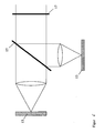
caractérisé en ce que, pour le calibrage de la répartition de lumière enregistrée au niveau d'un ou de plusieurs détecteurs (11) il est prévu un objet de calibrage (53) qui est introduit à la place de l'échantillon ou qui est monté dans le système optique dans un plan image conjugué par rapport à l'échantillon, ou peut être amené dans une position, et l'objet de calibrage (53) a des propriétés d'échantillons homogènes et/ou connues et est de préférence plan. - Dispositif pour engendrer des images optiques en coupe selon la revendication 1 ou 2,
caractérisé en ce que le ou les détecteurs (11) à résolution locale détectent une lumière fluorescente émise par l'échantillon et/ou une lumière luminescente engendrée dans l'échantillon, et il se produit une excitation modulée dans le temps par l'unité d'éclairage en combinaison avec une détection synchrone ou à résolution temporelle, et la durée de fluorescence et/ou la durée de luminescence est déterminée. - Dispositif pour engendrer des images optiques en coupe selon la revendication 1 ou 2,
caractérisé en ce que l'unité d'éclairage (1) utilise, pour engendrer les répartitions d'éclairage dans ou sur l'échantillon, un masque en transmission et/ou en réflexion, ou encore un masque de phase ou un élément pixelisé, ou la structure d'éclairage est engendrée par interférence d'ondes planes. - Dispositif pour engendrer des images optiques en coupe selon la revendication 1 ou 2,
caractérisé en ce que l'unité d'éclairage (1) engendre deux répartitions d'éclairage qui sont décalées en phase de 180° l'une par rapport à l'autre. - Dispositif pour engendrer des images optiques en coupe selon la revendication 1 ou 2,
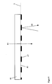
caractérisé en ce que les deux répartitions d'éclairage sont engendrées dans l'unité d'éclairage (1) par éclairage d'une structure en masque du côté avant ou du côté arrière. - Dispositif pour engendrer des images optiques en coupe selon la revendication 1 ou 2,
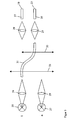
caractérisé en ce que les deux répartitions d'éclairage dans l'unité d'éclairage (1) sont configurées par commutation électronique de sources de lumière et/ou par commutation de commutateurs à fibres optiques. - Dispositif pour engendrer des images optiques en coupe selon la revendication 1 ou 2,
caractérisé en ce que l'agencement permet une inversion de la composition spectrale de la lumière émise par l'unité d'éclairage et/ou de la lumière enregistrée par ledit au moins un détecteur à résolution locale (11).
Applications Claiming Priority (2)
| Application Number | Priority Date | Filing Date | Title |
|---|---|---|---|
| DE102007018048A DE102007018048A1 (de) | 2007-04-13 | 2007-04-13 | Verfahren und Anordnung zur optischen Abbildung mit Tiefendiskriminierung |
| PCT/EP2008/054390 WO2008125605A2 (fr) | 2007-04-13 | 2008-04-11 | Procédé et dispositif de reproduction optique à discrimination en profondeur |
Publications (2)
| Publication Number | Publication Date |
|---|---|
| EP2137488A2 EP2137488A2 (fr) | 2009-12-30 |
| EP2137488B1 true EP2137488B1 (fr) | 2012-08-08 |
Family
ID=39642649
Family Applications (1)
| Application Number | Title | Priority Date | Filing Date |
|---|---|---|---|
| EP08736106A Active EP2137488B1 (fr) | 2007-04-13 | 2008-04-11 | Procédé et dispositif de reproduction optique à discrimination en profondeur |
Country Status (5)
| Country | Link |
|---|---|
| US (1) | US7977625B2 (fr) |
| EP (1) | EP2137488B1 (fr) |
| CN (1) | CN101680749B (fr) |
| DE (1) | DE102007018048A1 (fr) |
| WO (1) | WO2008125605A2 (fr) |
Cited By (1)
| Publication number | Priority date | Publication date | Assignee | Title |
|---|---|---|---|---|
| DE102017205474A1 (de) * | 2017-03-31 | 2018-10-04 | Robert Bosch Gmbh | Vorrichtung, beispielsweise für einen LIDAR-Sensor, zum Erzeugen von variablen Interferenzmustern und Verfahren zum Betreiben einer solchen Vorrichtung |
Families Citing this family (79)
| Publication number | Priority date | Publication date | Assignee | Title |
|---|---|---|---|---|
| WO2010077205A1 (fr) * | 2009-01-05 | 2010-07-08 | Ge Healthcare Bio-Sciences Corp | Système et procédé pour obtenir simultanément une pluralité d'images dans un système d'imagerie |
| DE102009009950A1 (de) | 2009-02-23 | 2010-10-21 | Confovis Gmbh | Anordnung und Verfahren für die Gewinnung von dreidimensionalen Objektdaten |
| EP2223650A1 (fr) * | 2009-02-25 | 2010-09-01 | The Provost, Fellows and Scholars of the College of the Holy and Undivided Trinity of Queen Elizabeth near Dublin | Procédé et appareil d'imagerie de tomographie de tissus |
| GB0907965D0 (en) * | 2009-05-08 | 2009-06-24 | King S College London | Imaging system |
| DK2442720T3 (en) | 2009-06-17 | 2016-12-19 | 3Shape As | Focus scan devices |
| EP2314200B1 (fr) * | 2009-10-21 | 2016-01-13 | SIS AG, Surgical Instrument Systems | Dispositif et procédé destinés à la mesure d'une cornée |
| US8414124B2 (en) | 2009-10-21 | 2013-04-09 | Sis Ag, Surgical Instrument Systems | Device and method for measuring a cornea |
| ES2364916B1 (es) * | 2010-03-05 | 2012-09-04 | Consejo Superior De Investigaciones Científicas (Csic) | Instrumento para la realizacion de imagenes de campo ancho a distintas profundidades de un especimen |
| WO2011119678A2 (fr) | 2010-03-23 | 2011-09-29 | California Institute Of Technology | Microscopes optofluidiques super-résolution pour une imagerie en deux dimensions (2d) et en trois dimensions (3d) |
| DE102010016598A1 (de) * | 2010-04-23 | 2011-10-27 | Leica Microsystems Cms Gmbh | Verfahren zum Untersuchen einer fluoreszierende Farbstoffe enthaltenden Probe mit Hilfe eines Mikroskops |
| JP2011229625A (ja) * | 2010-04-26 | 2011-11-17 | Fujifilm Corp | 内視鏡装置 |
| JP2011229603A (ja) * | 2010-04-26 | 2011-11-17 | Fujifilm Corp | 内視鏡装置 |
| US10010268B2 (en) * | 2010-09-15 | 2018-07-03 | Olympus Corporation | Endoscope apparatus |
| EP2437027A3 (fr) | 2010-10-03 | 2012-05-30 | Confovis GmbH | Dispositif et procédé de balayage optique tridimensionnel d'un échantillon |
| US9426429B2 (en) | 2010-10-26 | 2016-08-23 | California Institute Of Technology | Scanning projective lensless microscope system |
| US9569664B2 (en) * | 2010-10-26 | 2017-02-14 | California Institute Of Technology | Methods for rapid distinction between debris and growing cells |
| US9643184B2 (en) * | 2010-10-26 | 2017-05-09 | California Institute Of Technology | e-Petri dishes, devices, and systems having a light detector for sampling a sequence of sub-pixel shifted projection images |
| US9343494B2 (en) | 2011-03-03 | 2016-05-17 | California Institute Of Technology | Light guided pixel configured for emissions detection and comprising a guide layer with a wavelength selective filter material and a light detector layer |
| DE102011017046A1 (de) * | 2011-04-14 | 2012-10-18 | Till Photonics Gmbh | Umschaltbare Mikroskopanordnung mit mehreren Detektoren |
| JP5839907B2 (ja) * | 2011-09-15 | 2016-01-06 | キヤノン株式会社 | 画像処理装置および画像処理方法 |
| DE102011114932A1 (de) | 2011-10-06 | 2013-04-11 | Hommel-Etamic Gmbh | Verfahren zur Ermittlung einer Kontur einer Oberfläche |
| US8340456B1 (en) * | 2011-10-13 | 2012-12-25 | General Electric Company | System and method for depth from defocus imaging |
| US9245445B2 (en) * | 2012-02-21 | 2016-01-26 | Ricoh Co., Ltd. | Optical target detection |
| DE102012007045B4 (de) * | 2012-04-05 | 2023-03-16 | Carl Zeiss Microscopy Gmbh | Vorrichtung und Verfahren zur Mikroskopie |
| DE102012009836A1 (de) | 2012-05-16 | 2013-11-21 | Carl Zeiss Microscopy Gmbh | Lichtmikroskop und Verfahren zur Bildaufnahme mit einem Lichtmikroskop |
| AU2013202804A1 (en) * | 2012-06-14 | 2014-01-16 | Gen-Probe Incorporated | Use of a fluorescent material to detect failure or deteriorated performance of a fluorometer |
| DE102012017920B4 (de) * | 2012-09-11 | 2023-11-30 | Carl Zeiss Microscopy Gmbh | Optikanordnung und Lichtmikroskop |
| DE102012017922B4 (de) | 2012-09-11 | 2024-03-14 | Carl Zeiss Microscopy Gmbh | Optikanordnung und Lichtmikroskop |
| JP6128822B2 (ja) * | 2012-12-05 | 2017-05-17 | オリンパス株式会社 | 光学装置 |
| JP6161276B2 (ja) | 2012-12-12 | 2017-07-12 | キヤノン株式会社 | 測定装置、測定方法、及びプログラム |
| US20140235948A1 (en) * | 2013-02-19 | 2014-08-21 | The Board Of Trustees Of The Leland Stanford Junior University | Method for single-fiber microscopy using intensity-pattern sampling and optimization-based reconstruction |
| CN105026916B (zh) * | 2013-03-06 | 2017-07-14 | 浜松光子学株式会社 | 荧光受光装置以及荧光受光方法 |
| DE102013103333A1 (de) * | 2013-04-03 | 2014-10-09 | Karl Storz Gmbh & Co. Kg | Kamera zur Erfassung von optischen Eigenschaften und von Raumstruktureigenschaften |
| DE102013218231A1 (de) * | 2013-09-11 | 2015-03-12 | Sirona Dental Systems Gmbh | Optisches System zur Erzeugung eines sich zeitlich ändernden Musters für ein Konfokalmikroskop |
| US9618450B2 (en) * | 2013-09-27 | 2017-04-11 | Ecolab USA, Inc. | Multi-channel fluorometric sensor and method of using same |
| EP3052895B1 (fr) * | 2013-10-01 | 2021-06-16 | Renishaw PLC | Procédé de fabrication d'un composant électronique |
| EP2879004A1 (fr) * | 2013-12-02 | 2015-06-03 | IMEC vzw | Appareil et procédé permettant d'effectuer l'holographie numérique en ligne sans lentille d'un objet |
| WO2015118120A1 (fr) | 2014-02-07 | 2015-08-13 | 3Shape A/S | Détection d'une nuance de dent |
| JP6378931B2 (ja) * | 2014-05-21 | 2018-08-22 | 浜松ホトニクス株式会社 | 顕微鏡装置及び画像取得方法 |
| DE102014009372A1 (de) * | 2014-06-23 | 2015-12-24 | Fraunhofer-Gesellschaft zur Förderung der angewandten Forschung e.V. | Anordnung zur Bestimmung von Eigenschaften und/oder Parametern einer Probe und/oder mindestens einer auf oder an einer Oberfläche einer Probe ausgebildeten Schicht |
| US9675430B2 (en) | 2014-08-15 | 2017-06-13 | Align Technology, Inc. | Confocal imaging apparatus with curved focal surface |
| DE102014113258A1 (de) * | 2014-09-15 | 2016-03-17 | Carl Zeiss Ag | Verfahren zum Erzeugen eines Ergebnisbilds und optische Vorrichtung |
| CN104296660A (zh) * | 2014-11-05 | 2015-01-21 | 哈尔滨工业大学 | 基于结构光方法的微观光滑自由曲面样品测量装置和方法 |
| CN104570315B (zh) * | 2014-12-30 | 2017-06-27 | 中国科学院西安光学精密机械研究所 | 一种基于结构照明的彩色三维层析显微成像系统及方法 |
| DE102015208080A1 (de) * | 2015-04-30 | 2016-11-03 | Carl Zeiss Microscopy Gmbh | Verfahren zur Reflexionskorrektur von Abbildungen und diesbezügliche Vorrichtungen |
| DE102015209402A1 (de) * | 2015-05-22 | 2016-11-24 | Sirona Dental Systems Gmbh | Vorrichtung zur optischen 3D-Vermessung eines Objekts |
| DE102015210016A1 (de) | 2015-06-01 | 2016-12-01 | Carl Zeiss Microscopy Gmbh | Verfahren zum Ermitteln einer ortsaufgelösten Höheninformation einer Probe mit einem Weitfeldmikroskop und Weitfeldmikroskop |
| DE102015108912A1 (de) | 2015-06-05 | 2016-12-08 | Carl Zeiss Microscopy Gmbh | Vorrichtung und Verfahren zur Erfassung von Oberflächentopographien |
| DE102015217091B4 (de) | 2015-09-07 | 2017-05-11 | Fraunhofer-Gesellschaft zur Förderung der angewandten Forschung e.V | Anordnung zur Bestimmung der erreichbaren Haftfestigkeit vor Ausbildung einer stoffschlüssigen Verbindung an einer Oberfläche eines Fügepartners |
| US10725279B2 (en) * | 2016-04-08 | 2020-07-28 | Arizona Board Of Regents On Behalf Of The University Of Arizona | Systems and methods for extended depth-of-field microscopy |
| LU93022B1 (de) * | 2016-04-08 | 2017-11-08 | Leica Microsystems | Verfahren und Mikroskop zum Untersuchen einer Probe |
| JP2017207329A (ja) * | 2016-05-17 | 2017-11-24 | Juki株式会社 | 照明装置及び検査装置 |
| DE102016117803A1 (de) | 2016-09-21 | 2018-03-22 | Leica Microsystems Cms Gmbh | Mikroskopbeleuchtungsanordnung zur strukturierten Beleuchtung |
| US11889979B2 (en) * | 2016-12-30 | 2024-02-06 | Barco Nv | System and method for camera calibration |
| DE102017213549B3 (de) * | 2017-08-04 | 2018-09-27 | Ifm Electronic Gmbh | Lichtschnittsensor und Verfahren zum Betreiben eines Lichtschnittsensors |
| CN107621463B (zh) * | 2017-10-16 | 2024-03-22 | 苏州微景医学科技有限公司 | 图像重建方法、装置及显微成像装置 |
| DE102017009804A1 (de) * | 2017-10-20 | 2019-04-25 | Vermicon Ag | Verfahren zur Bewertung von mikroskopischen Proben und Vorrichtung zur Ausführung dieses Verfahrens |
| EP3486706B1 (fr) * | 2017-11-16 | 2024-05-08 | SD Optics, Inc. | Module fonctionnel et microscope en étant équipé |
| WO2019135069A1 (fr) * | 2018-01-02 | 2019-07-11 | King's College London | Procédé et système pour microscopie de localisation |
| TWI699559B (zh) * | 2018-01-16 | 2020-07-21 | 美商伊路米納有限公司 | 結構照明成像系統和使用結構化光來創建高解析度圖像的方法 |
| CN108303373B (zh) * | 2018-02-01 | 2021-01-22 | 京东方科技集团股份有限公司 | 一种检测消影等级的装置及其控制方法 |
| JP7099367B2 (ja) * | 2019-03-06 | 2022-07-12 | 株式会社ダイフク | 検査システム |
| US11469075B2 (en) | 2019-03-14 | 2022-10-11 | Applied Materials, Inc. | Identifying fiducial markers in microscope images |
| US11255785B2 (en) * | 2019-03-14 | 2022-02-22 | Applied Materials, Inc. | Identifying fiducial markers in fluorescence microscope images |
| CN110207609B (zh) * | 2019-04-25 | 2021-03-23 | 合刃科技(武汉)有限公司 | 基于多种光谱的主动光的三维成像方法、装置及存储介质 |
| CN110057743A (zh) * | 2019-05-06 | 2019-07-26 | 西安交通大学 | 基于光学虚拟染色的血涂片免标记细胞三维形态检测方法 |
| CN110233973B (zh) * | 2019-05-28 | 2021-01-15 | 怀光智能科技(武汉)有限公司 | 一种玻片扫描仪光源 |
| DE102019212520A1 (de) * | 2019-08-21 | 2021-02-25 | Carl Zeiss Smt Gmbh | Diffraktives optisches Element für ein Prüfinterferometer |
| KR102116232B1 (ko) * | 2019-11-12 | 2020-05-28 | (주)로고스바이오시스템스 | 시료 검출 장치 및 이를 이용한 시료 검출 방법 |
| CN110824690B (zh) * | 2019-11-13 | 2020-09-29 | 河北工程大学 | 一种基于大数据的司法痕检用全息显微设备 |
| WO2021168612A1 (fr) | 2020-02-24 | 2021-09-02 | Yangtze Memory Technologies Co., Ltd. | Systèmes et procédés de métrologie de topographie de surface de puce semi-conductrice |
| CN113008160B (zh) | 2020-02-24 | 2023-02-10 | 长江存储科技有限责任公司 | 用于半导体芯片表面形貌计量的系统和方法 |
| CN111356896B (zh) | 2020-02-24 | 2021-01-12 | 长江存储科技有限责任公司 | 用于半导体芯片表面形貌计量的系统和方法 |
| WO2021168610A1 (fr) | 2020-02-24 | 2021-09-02 | Yangtze Memory Technologies Co., Ltd. | Systèmes ayant une source de lumière à spectre étendu pour métrologie de topographie de surface de puce à semi-conducteurs |
| DE102021110263A1 (de) | 2021-04-22 | 2022-10-27 | MAX-PLANCK-Gesellschaft zur Förderung der Wissenschaften e.V. | Verfahren und Beleuchtungsvorrichtung der adaptiven Optik in der Reflexionsmikroskopie |
| CN113252633B (zh) * | 2021-07-14 | 2021-10-12 | 季华实验室 | 一种液相芯片分析仪的质控检测方法及标准盘 |
| CN115061270B (zh) * | 2022-05-30 | 2024-01-16 | 中国人民解放军国防科技大学 | 一种倾斜模式望远显微组合成像方法 |
| DE102022213412A1 (de) | 2022-12-12 | 2024-06-13 | Robert Bosch Gesellschaft mit beschränkter Haftung | Vorrichtung und Verfahren zur dynamischen Fluoreszenzanalyse, insbesondere für die Molekulardiagnostik |
| CN116892883B (zh) * | 2023-09-11 | 2023-11-28 | 深圳市深视智能科技有限公司 | 一种倾角位移传感器及光学防抖系统 |
Family Cites Families (15)
| Publication number | Priority date | Publication date | Assignee | Title |
|---|---|---|---|---|
| US3013467A (en) | 1957-11-07 | 1961-12-19 | Minsky Marvin | Microscopy apparatus |
| GB9102903D0 (en) * | 1991-02-12 | 1991-03-27 | Oxford Sensor Tech | An optical sensor |
| ATE208911T1 (de) | 1997-04-04 | 2001-11-15 | Isis Innovation | Abbildungssystem und -verfahren für mikroskopie |
| DE69841107D1 (de) | 1997-07-12 | 2009-10-08 | Roper Ind Inc | Multispektraler zweidimensionaler bildgebeuder spekteometer |
| GB9901365D0 (en) | 1999-01-22 | 1999-03-10 | Isis Innovations Ltd | Confocal microscopy apparatus and method |
| JP4429431B2 (ja) * | 1999-10-21 | 2010-03-10 | オリンパス株式会社 | 光学装置 |
| JP2001330555A (ja) * | 2000-05-19 | 2001-11-30 | Yokogawa Electric Corp | 光スキャナ及びこれを用いた断層画像取得装置 |
| US6628381B1 (en) * | 2000-06-20 | 2003-09-30 | Applied Materials, Inc. | Optical inspection method and apparatus utilizing a collection angle design |
| DE10038527A1 (de) | 2000-08-08 | 2002-02-21 | Zeiss Carl Jena Gmbh | Anordnung zur Erhöhung der Tiefendiskriminierung optisch abbildender Systeme |
| DE10118463A1 (de) | 2001-04-07 | 2002-10-10 | Zeiss Carl Jena Gmbh | Verfahren und Anordnung zur tiefenaufgelösten optischen Erfassung einer Probe |
| GB0200819D0 (en) | 2002-01-15 | 2002-03-06 | Cole Polytechnique Federale De | Microscopy imaging apparatus and method for generating an image |
| DE10204430A1 (de) | 2002-02-04 | 2003-08-07 | Zeiss Carl | Stereo-Mikroskopieverfahren und Stereo-Mikroskopiesystem |
| DE10254139A1 (de) | 2002-11-15 | 2004-05-27 | Carl Zeiss Jena Gmbh | Verfahren und Anordnung zur tiefenaufgelösten optischen Erfassung einer Probe |
| US7041998B2 (en) * | 2003-03-24 | 2006-05-09 | Photon Dynamics, Inc. | Method and apparatus for high-throughput inspection of large flat patterned media using dynamically programmable optical spatial filtering |
| US7115848B1 (en) * | 2004-09-29 | 2006-10-03 | Qioptiq Imaging Solutions, Inc. | Methods, systems and computer program products for calibration of microscopy imaging devices |
-
2007
- 2007-04-13 DE DE102007018048A patent/DE102007018048A1/de not_active Ceased
-
2008
- 2008-04-11 US US12/450,759 patent/US7977625B2/en active Active
- 2008-04-11 WO PCT/EP2008/054390 patent/WO2008125605A2/fr active Application Filing
- 2008-04-11 CN CN2008800185091A patent/CN101680749B/zh active Active
- 2008-04-11 EP EP08736106A patent/EP2137488B1/fr active Active
Cited By (1)
| Publication number | Priority date | Publication date | Assignee | Title |
|---|---|---|---|---|
| DE102017205474A1 (de) * | 2017-03-31 | 2018-10-04 | Robert Bosch Gmbh | Vorrichtung, beispielsweise für einen LIDAR-Sensor, zum Erzeugen von variablen Interferenzmustern und Verfahren zum Betreiben einer solchen Vorrichtung |
Also Published As
| Publication number | Publication date |
|---|---|
| US20100108873A1 (en) | 2010-05-06 |
| WO2008125605A3 (fr) | 2009-02-26 |
| WO2008125605A2 (fr) | 2008-10-23 |
| US7977625B2 (en) | 2011-07-12 |
| DE102007018048A1 (de) | 2008-10-16 |
| EP2137488A2 (fr) | 2009-12-30 |
| CN101680749A (zh) | 2010-03-24 |
| CN101680749B (zh) | 2013-07-10 |
Similar Documents
| Publication | Publication Date | Title |
|---|---|---|
| EP2137488B1 (fr) | Procédé et dispositif de reproduction optique à discrimination en profondeur | |
| DE102006007172B4 (de) | Verfahren und Anordnung zur schnellen, ortsaufgelösten, flächigen, spektroskopischen Analyse, bzw. zum Spectral Imaging oder zur 3D-Erfassung mittels Spektroskopie | |
| EP1248132B1 (fr) | Méthode et dispositif de détection optique à résolution de la profondeur d'un échantillon | |
| DE102011114500B4 (de) | Mikroskopvorrichtung | |
| EP2860566B1 (fr) | Microscopie à balayage haute résolution | |
| DE102013016368B4 (de) | Lichtmikroskop und Mikroskopieverfahren zum Untersuchen einer mikroskopischen Probe | |
| EP1264169B1 (fr) | Augmentation de la resolution spectrale et/ou spatiale dans un microscope a balayage laser | |
| WO2013171309A1 (fr) | Microscope optique et procédé de prise de vues au moyen d'un microscope optique | |
| DE102011055294B4 (de) | Mikroskopische Einrichtung und Verfahren zur dreidimensionalen Lokalisierung von punktförmigen Objekten in einer Probe | |
| DE102004053730B4 (de) | Verfahren und Anordnung zur Unterdrückung von Falschlicht | |
| EP3058414B1 (fr) | Microscope à balayage et procédé de détermination de la fonction d'étalement ponctuel d'un microscope à balayage | |
| EP2038690A2 (fr) | Procédé et dispositif destinés à produire une image d'une couche mince d'un objet | |
| EP3056934B1 (fr) | Tete de mesure d'un dispositif endoscopique et procede d'inspection et mesure d'un objet | |
| DE19626261A1 (de) | Beobachtungsvorrichtung | |
| EP3948392B1 (fr) | Procédé et dispositif de détection de déplacements d'un échantillon par rapport à un objectif | |
| WO2016193037A1 (fr) | Procédé pour la détermination d'une information de hauteur à résolution spatiale d'un échantillon au moyen d'un microscope à champ large et microscope à champ large | |
| DE10155002A1 (de) | Verfahren und Anordnung zur tiefenaufgelösten optischen Erfassung einer Probe | |
| DE102020209889A1 (de) | Mikroskop und Verfahren zur mikroskopischen Bildaufnahme mit variabler Beleuchtung | |
| DE102013016367A1 (de) | Lichtmikroskop und Verfahren zum Untersuchen einer Probe mit einem Lichtmikroskop | |
| DE10118463A1 (de) | Verfahren und Anordnung zur tiefenaufgelösten optischen Erfassung einer Probe | |
| DE102007047468A1 (de) | Verfahren und Anordnung zur optischen Erfassung einer beleuchteten Probe | |
| EP3953684A1 (fr) | Microscope à feuille de lumière et procédé de détermination de l'indice de réfraction d'objets dans la chambre à échantillons | |
| DE102015108912A1 (de) | Vorrichtung und Verfahren zur Erfassung von Oberflächentopographien | |
| EP1794572B1 (fr) | Procede d'exploitation d'un systeme interferometrique avec un element de reference pourvu d'une ou plusieurs zones reflechissantes | |
| DE102018126009A1 (de) | Verfahren und Mikroskop zur Bestimmung der Dicke eines Deck- oder Tragglases |
Legal Events
| Date | Code | Title | Description |
|---|---|---|---|
| PUAI | Public reference made under article 153(3) epc to a published international application that has entered the european phase |
Free format text: ORIGINAL CODE: 0009012 |
|
| 17P | Request for examination filed |
Effective date: 20091102 |
|
| AK | Designated contracting states |
Kind code of ref document: A2 Designated state(s): AT BE BG CH CY CZ DE DK EE ES FI FR GB GR HR HU IE IS IT LI LT LU LV MC MT NL NO PL PT RO SE SI SK TR |
|
| 17Q | First examination report despatched |
Effective date: 20100112 |
|
| GRAP | Despatch of communication of intention to grant a patent |
Free format text: ORIGINAL CODE: EPIDOSNIGR1 |
|
| DAX | Request for extension of the european patent (deleted) | ||
| GRAS | Grant fee paid |
Free format text: ORIGINAL CODE: EPIDOSNIGR3 |
|
| GRAA | (expected) grant |
Free format text: ORIGINAL CODE: 0009210 |
|
| AK | Designated contracting states |
Kind code of ref document: B1 Designated state(s): AT BE BG CH CY CZ DE DK EE ES FI FR GB GR HR HU IE IS IT LI LT LU LV MC MT NL NO PL PT RO SE SI SK TR |
|
| REG | Reference to a national code |
Ref country code: GB Ref legal event code: FG4D Free format text: NOT ENGLISH |
|
| REG | Reference to a national code |
Ref country code: CH Ref legal event code: EP Ref country code: AT Ref legal event code: REF Ref document number: 569997 Country of ref document: AT Kind code of ref document: T Effective date: 20120815 |
|
| REG | Reference to a national code |
Ref country code: IE Ref legal event code: FG4D Free format text: LANGUAGE OF EP DOCUMENT: GERMAN |
|
| REG | Reference to a national code |
Ref country code: DE Ref legal event code: R096 Ref document number: 502008007891 Country of ref document: DE Effective date: 20121004 |
|
| REG | Reference to a national code |
Ref country code: NL Ref legal event code: VDEP Effective date: 20120808 |
|
| REG | Reference to a national code |
Ref country code: LT Ref legal event code: MG4D Effective date: 20120808 |
|
| PG25 | Lapsed in a contracting state [announced via postgrant information from national office to epo] |
Ref country code: FI Free format text: LAPSE BECAUSE OF FAILURE TO SUBMIT A TRANSLATION OF THE DESCRIPTION OR TO PAY THE FEE WITHIN THE PRESCRIBED TIME-LIMIT Effective date: 20120808 Ref country code: HR Free format text: LAPSE BECAUSE OF FAILURE TO SUBMIT A TRANSLATION OF THE DESCRIPTION OR TO PAY THE FEE WITHIN THE PRESCRIBED TIME-LIMIT Effective date: 20120808 Ref country code: IS Free format text: LAPSE BECAUSE OF FAILURE TO SUBMIT A TRANSLATION OF THE DESCRIPTION OR TO PAY THE FEE WITHIN THE PRESCRIBED TIME-LIMIT Effective date: 20121208 Ref country code: LT Free format text: LAPSE BECAUSE OF FAILURE TO SUBMIT A TRANSLATION OF THE DESCRIPTION OR TO PAY THE FEE WITHIN THE PRESCRIBED TIME-LIMIT Effective date: 20120808 Ref country code: CY Free format text: LAPSE BECAUSE OF FAILURE TO SUBMIT A TRANSLATION OF THE DESCRIPTION OR TO PAY THE FEE WITHIN THE PRESCRIBED TIME-LIMIT Effective date: 20120808 Ref country code: NO Free format text: LAPSE BECAUSE OF FAILURE TO SUBMIT A TRANSLATION OF THE DESCRIPTION OR TO PAY THE FEE WITHIN THE PRESCRIBED TIME-LIMIT Effective date: 20121108 |
|
| PG25 | Lapsed in a contracting state [announced via postgrant information from national office to epo] |
Ref country code: GR Free format text: LAPSE BECAUSE OF FAILURE TO SUBMIT A TRANSLATION OF THE DESCRIPTION OR TO PAY THE FEE WITHIN THE PRESCRIBED TIME-LIMIT Effective date: 20121109 Ref country code: SI Free format text: LAPSE BECAUSE OF FAILURE TO SUBMIT A TRANSLATION OF THE DESCRIPTION OR TO PAY THE FEE WITHIN THE PRESCRIBED TIME-LIMIT Effective date: 20120808 Ref country code: SE Free format text: LAPSE BECAUSE OF FAILURE TO SUBMIT A TRANSLATION OF THE DESCRIPTION OR TO PAY THE FEE WITHIN THE PRESCRIBED TIME-LIMIT Effective date: 20120808 Ref country code: PL Free format text: LAPSE BECAUSE OF FAILURE TO SUBMIT A TRANSLATION OF THE DESCRIPTION OR TO PAY THE FEE WITHIN THE PRESCRIBED TIME-LIMIT Effective date: 20120808 Ref country code: LV Free format text: LAPSE BECAUSE OF FAILURE TO SUBMIT A TRANSLATION OF THE DESCRIPTION OR TO PAY THE FEE WITHIN THE PRESCRIBED TIME-LIMIT Effective date: 20120808 Ref country code: PT Free format text: LAPSE BECAUSE OF FAILURE TO SUBMIT A TRANSLATION OF THE DESCRIPTION OR TO PAY THE FEE WITHIN THE PRESCRIBED TIME-LIMIT Effective date: 20121210 |
|
| PG25 | Lapsed in a contracting state [announced via postgrant information from national office to epo] |
Ref country code: NL Free format text: LAPSE BECAUSE OF FAILURE TO SUBMIT A TRANSLATION OF THE DESCRIPTION OR TO PAY THE FEE WITHIN THE PRESCRIBED TIME-LIMIT Effective date: 20120808 |
|
| PG25 | Lapsed in a contracting state [announced via postgrant information from national office to epo] |
Ref country code: EE Free format text: LAPSE BECAUSE OF FAILURE TO SUBMIT A TRANSLATION OF THE DESCRIPTION OR TO PAY THE FEE WITHIN THE PRESCRIBED TIME-LIMIT Effective date: 20120808 Ref country code: DK Free format text: LAPSE BECAUSE OF FAILURE TO SUBMIT A TRANSLATION OF THE DESCRIPTION OR TO PAY THE FEE WITHIN THE PRESCRIBED TIME-LIMIT Effective date: 20120808 Ref country code: ES Free format text: LAPSE BECAUSE OF FAILURE TO SUBMIT A TRANSLATION OF THE DESCRIPTION OR TO PAY THE FEE WITHIN THE PRESCRIBED TIME-LIMIT Effective date: 20121119 Ref country code: CZ Free format text: LAPSE BECAUSE OF FAILURE TO SUBMIT A TRANSLATION OF THE DESCRIPTION OR TO PAY THE FEE WITHIN THE PRESCRIBED TIME-LIMIT Effective date: 20120808 Ref country code: RO Free format text: LAPSE BECAUSE OF FAILURE TO SUBMIT A TRANSLATION OF THE DESCRIPTION OR TO PAY THE FEE WITHIN THE PRESCRIBED TIME-LIMIT Effective date: 20120808 |
|
| PG25 | Lapsed in a contracting state [announced via postgrant information from national office to epo] |
Ref country code: IT Free format text: LAPSE BECAUSE OF FAILURE TO SUBMIT A TRANSLATION OF THE DESCRIPTION OR TO PAY THE FEE WITHIN THE PRESCRIBED TIME-LIMIT Effective date: 20120808 Ref country code: SK Free format text: LAPSE BECAUSE OF FAILURE TO SUBMIT A TRANSLATION OF THE DESCRIPTION OR TO PAY THE FEE WITHIN THE PRESCRIBED TIME-LIMIT Effective date: 20120808 |
|
| PLBE | No opposition filed within time limit |
Free format text: ORIGINAL CODE: 0009261 |
|
| STAA | Information on the status of an ep patent application or granted ep patent |
Free format text: STATUS: NO OPPOSITION FILED WITHIN TIME LIMIT |
|
| 26N | No opposition filed |
Effective date: 20130510 |
|
| PG25 | Lapsed in a contracting state [announced via postgrant information from national office to epo] |
Ref country code: BG Free format text: LAPSE BECAUSE OF FAILURE TO SUBMIT A TRANSLATION OF THE DESCRIPTION OR TO PAY THE FEE WITHIN THE PRESCRIBED TIME-LIMIT Effective date: 20121108 |
|
| REG | Reference to a national code |
Ref country code: DE Ref legal event code: R097 Ref document number: 502008007891 Country of ref document: DE Effective date: 20130510 |
|
| BERE | Be: lapsed |
Owner name: SCHWERTNER, MICHAEL Effective date: 20130430 |
|
| PG25 | Lapsed in a contracting state [announced via postgrant information from national office to epo] |
Ref country code: MC Free format text: LAPSE BECAUSE OF FAILURE TO SUBMIT A TRANSLATION OF THE DESCRIPTION OR TO PAY THE FEE WITHIN THE PRESCRIBED TIME-LIMIT Effective date: 20120808 |
|
| REG | Reference to a national code |
Ref country code: CH Ref legal event code: PL |
|
| GBPC | Gb: european patent ceased through non-payment of renewal fee |
Effective date: 20130411 |
|
| REG | Reference to a national code |
Ref country code: IE Ref legal event code: MM4A |
|
| PG25 | Lapsed in a contracting state [announced via postgrant information from national office to epo] |
Ref country code: GB Free format text: LAPSE BECAUSE OF NON-PAYMENT OF DUE FEES Effective date: 20130411 Ref country code: CH Free format text: LAPSE BECAUSE OF NON-PAYMENT OF DUE FEES Effective date: 20130430 Ref country code: BE Free format text: LAPSE BECAUSE OF NON-PAYMENT OF DUE FEES Effective date: 20130430 Ref country code: LI Free format text: LAPSE BECAUSE OF NON-PAYMENT OF DUE FEES Effective date: 20130430 |
|
| REG | Reference to a national code |
Ref country code: FR Ref legal event code: ST Effective date: 20131231 |
|
| PG25 | Lapsed in a contracting state [announced via postgrant information from national office to epo] |
Ref country code: FR Free format text: LAPSE BECAUSE OF NON-PAYMENT OF DUE FEES Effective date: 20130430 |
|
| PG25 | Lapsed in a contracting state [announced via postgrant information from national office to epo] |
Ref country code: IE Free format text: LAPSE BECAUSE OF NON-PAYMENT OF DUE FEES Effective date: 20130411 |
|
| REG | Reference to a national code |
Ref country code: AT Ref legal event code: MM01 Ref document number: 569997 Country of ref document: AT Kind code of ref document: T Effective date: 20130411 |
|
| PG25 | Lapsed in a contracting state [announced via postgrant information from national office to epo] |
Ref country code: AT Free format text: LAPSE BECAUSE OF NON-PAYMENT OF DUE FEES Effective date: 20130411 |
|
| PG25 | Lapsed in a contracting state [announced via postgrant information from national office to epo] |
Ref country code: MT Free format text: LAPSE BECAUSE OF FAILURE TO SUBMIT A TRANSLATION OF THE DESCRIPTION OR TO PAY THE FEE WITHIN THE PRESCRIBED TIME-LIMIT Effective date: 20120808 |
|
| PG25 | Lapsed in a contracting state [announced via postgrant information from national office to epo] |
Ref country code: TR Free format text: LAPSE BECAUSE OF FAILURE TO SUBMIT A TRANSLATION OF THE DESCRIPTION OR TO PAY THE FEE WITHIN THE PRESCRIBED TIME-LIMIT Effective date: 20120808 |
|
| PG25 | Lapsed in a contracting state [announced via postgrant information from national office to epo] |
Ref country code: HU Free format text: LAPSE BECAUSE OF FAILURE TO SUBMIT A TRANSLATION OF THE DESCRIPTION OR TO PAY THE FEE WITHIN THE PRESCRIBED TIME-LIMIT; INVALID AB INITIO Effective date: 20080411 Ref country code: LU Free format text: LAPSE BECAUSE OF NON-PAYMENT OF DUE FEES Effective date: 20130411 |
|
| PGFP | Annual fee paid to national office [announced via postgrant information from national office to epo] |
Ref country code: DE Payment date: 20240429 Year of fee payment: 17 |