EP2137488B1 - Method and assembly for optical reproduction with depth discrimination - Google Patents
Method and assembly for optical reproduction with depth discrimination Download PDFInfo
- Publication number
- EP2137488B1 EP2137488B1 EP08736106A EP08736106A EP2137488B1 EP 2137488 B1 EP2137488 B1 EP 2137488B1 EP 08736106 A EP08736106 A EP 08736106A EP 08736106 A EP08736106 A EP 08736106A EP 2137488 B1 EP2137488 B1 EP 2137488B1
- Authority
- EP
- European Patent Office
- Prior art keywords
- illumination
- sample
- light
- distributions
- optical
- Prior art date
- Legal status (The legal status is an assumption and is not a legal conclusion. Google has not performed a legal analysis and makes no representation as to the accuracy of the status listed.)
- Active
Links
Images


Classifications
-
- G—PHYSICS
- G01—MEASURING; TESTING
- G01B—MEASURING LENGTH, THICKNESS OR SIMILAR LINEAR DIMENSIONS; MEASURING ANGLES; MEASURING AREAS; MEASURING IRREGULARITIES OF SURFACES OR CONTOURS
- G01B11/00—Measuring arrangements characterised by the use of optical techniques
- G01B11/24—Measuring arrangements characterised by the use of optical techniques for measuring contours or curvatures
- G01B11/25—Measuring arrangements characterised by the use of optical techniques for measuring contours or curvatures by projecting a pattern, e.g. one or more lines, moiré fringes on the object
- G01B11/2504—Calibration devices
-
- G—PHYSICS
- G01—MEASURING; TESTING
- G01N—INVESTIGATING OR ANALYSING MATERIALS BY DETERMINING THEIR CHEMICAL OR PHYSICAL PROPERTIES
- G01N21/00—Investigating or analysing materials by the use of optical means, i.e. using sub-millimetre waves, infrared, visible or ultraviolet light
- G01N21/62—Systems in which the material investigated is excited whereby it emits light or causes a change in wavelength of the incident light
- G01N21/63—Systems in which the material investigated is excited whereby it emits light or causes a change in wavelength of the incident light optically excited
- G01N21/64—Fluorescence; Phosphorescence
- G01N21/645—Specially adapted constructive features of fluorimeters
- G01N21/6456—Spatial resolved fluorescence measurements; Imaging
- G01N21/6458—Fluorescence microscopy
-
- G—PHYSICS
- G02—OPTICS
- G02B—OPTICAL ELEMENTS, SYSTEMS OR APPARATUS
- G02B21/00—Microscopes
- G02B21/36—Microscopes arranged for photographic purposes or projection purposes or digital imaging or video purposes including associated control and data processing arrangements
- G02B21/365—Control or image processing arrangements for digital or video microscopes
- G02B21/367—Control or image processing arrangements for digital or video microscopes providing an output produced by processing a plurality of individual source images, e.g. image tiling, montage, composite images, depth sectioning, image comparison
-
- G—PHYSICS
- G06—COMPUTING; CALCULATING OR COUNTING
- G06T—IMAGE DATA PROCESSING OR GENERATION, IN GENERAL
- G06T7/00—Image analysis
- G06T7/50—Depth or shape recovery
- G06T7/55—Depth or shape recovery from multiple images
Definitions
- the U.S. Patent 5,381,236 [11] describes an optical sensor for determining the distance of three-dimensional objects ("range finding").
- range finding a periodic structure is projected into the object, whereby the illumination structure can be reversed, which corresponds to a phase shift of 180 degrees.
- the method proposed here is also based on the change of the projected structure in two steps, but has the following differences compared to [11]:
- the individual elements of the projected illumination structure must be exactly aligned to the individual elements of the detector (CCD pixel) in [11]. This is a severe limitation for several reasons:
- the optical assembly would need to closely follow the imaging scale to match the illumination pattern to the detector.
- the relative adjustment of the two structures would have to be realized very precisely and be sub-pixel accurate.
- Another aspect of the proposed device relates to the generation of optical slices wherein the sample is scanned at different wavelengths.
- This can lead to a problem with the axial chromatic properties of the optics, which has hitherto been e.g. was solved by a mechanical tracking of optical elements.
- arrangements are disclosed which solve the problem of axial chromatic correction in structured illumination, in particular when integrated into conventional microscope systems, without moving mechanical elements and offer further speed advantages over the prior art.
Abstract
Description
Die Erfindung betrifft eine Vorrichtung zur Erzeugung optischer Schnittbilder.The invention relates to a device for producing optical sectional images.
Die vorliegende Erfindung dient der dreidimensionalen, schichtweisen optischen Abtastung räumlich ausgedehnter Objekte und hat hauptsächlich Anwendungen in der Mikroskopie, ist jedoch nicht auf diesen Bereich beschränkt.
Um dreidimensionale Abbildungen von Objekten zu erhalten, bedient man sich oft der Technik des optischen Schneidens. Ein sogenannter optischer Schnitt ist eine Abbildung, welche nur Informationen aus einem bestimmten Tiefenbereich enthält. Ein optisches System zur Erstellung optischer Schnitte bildet deshalb selektiv Objektdetails ab, welche sich in der Fokusebene befinden, wobei Objektdetails, welche sich nicht in dieser Ebene befinden, im Schnittbild unterdrückt werden.The present invention is for three-dimensional, layer-by-layer optical scanning of spatially extended objects and has mainly applications in microscopy, but is not limited to this range.
In order to obtain three-dimensional images of objects, one often uses the technique of optical cutting. A so-called optical cut is an image that contains only information from a certain depth range. An optical system for producing optical sections therefore selectively forms object details which are located in the focal plane, wherein object details which are not in this plane are suppressed in the sectional image.
Durch die Aufnahme einer Serie von optischen Schnitten an unterschiedlichen Fokuspositionen kann ein 3D Objekt schrittweise abgetastet werden. Somit kann eine dreidimensionale Abbildung des Objektes erstellt oder seine Topologie analysiert werden. Die Begriffe Objekt und Probe werden im Folgenden gleichberechtigt verwendet. Insbesondere in der Mikroskopie wird das untersuchte Objekt oft als Probe bezeichnet.By capturing a series of optical sections at different focus positions, a 3D object can be scanned step by step. Thus, a three-dimensional image of the object can be created or its topology analyzed. The terms object and sample are used equally. Especially in microscopy, the examined object is often referred to as a sample.
Die vorliegende Erfindung ermöglicht die Erstellung von optischen Schnitten auf besonders einfache Weise und kann zum Beispiel in der Biologie, Medizin oder den Materialwissenschaften zur Analyse von Objekten verwendet werden.The present invention makes it possible to produce optical sections in a particularly simple manner and can be used, for example, in biology, medicine or materials science for the analysis of objects.
Eines der ersten Verfahren zur Erzeugung von optischen Schnitten war das konfokale Mikroskop von Minsky [1]. Hier wird die Abbildung von Bilddetails außerhalb der Fokusebene durch eine Anordnung von konfokalen Blenden unterdrückt.One of the first methods for producing optical sections was the Minsky confocal microscope [1]. Here, the imaging of image details outside the focal plane is suppressed by an array of confocal apertures.
Ein anderer Ansatz zur Erzeugung von optischen Schnitten ist die strukturierte Beleuchtung, wie sie zum Beispiel von Wilson et al. in [2] beschrieben ist. Hier wird eine Struktur, zum Beispiel ein Gitter, in die abzubildende Probe projiziert. Dies erzeugt eine Modulation der Lichtverteilung in der Probe. Wie zum Beispiel in [2] gezeigt wurde, ist die Modulationstiefe in der Fokusebene am stärksten und kennzeichnet in diesem Sinne die Fokusebene. Bei der strukturierten Beleuchtung wird zuerst eine Modulation dem Beleuchtungslicht aufgeprägt, danach eine Serie von Abbildungen für verschiedene Positionen (Phasenschritte) der projizierten Struktur aufgenommen und im letzten Schritt das optische Schnittbild aus den aufgenommenen Daten berechnet.
Hierzu wurden verschiedene Anordnungen vorgeschlagen. Im Patent von Wilson et al., [3] wird ein Gitter in einer der Probe konjugierten Ebene angeordnet und lateral zur optischen Achse verschoben. Bei Gerstner et al. [4][5] wird dagegen eine in den Strahlengang eingebrachte planparallele Platte gekippt, welche die in bzw. auf die Probe projizierte Beleuchtungsstruktur lateral verschiebt. Bei transparenten oder teiltransparenten Proben findet eine Projektion in die Probe statt, bei intransparenten Oberflächenstrukturen wird von einer Projektion auf die Probe gesprochen.
Eine andere Lösung wurde von Neil et al. [6] vorgeschlagen. Hier entsteht die Beleuchtungsstruktur in der Probe direkt durch Interferenz.Another approach to generating optical sections is structured illumination, as described, for example, by Wilson et al. in [2]. Here a structure, for example a grid, is projected into the sample to be imaged. This produces a modulation of the light distribution in the sample. For example, as shown in [2], the depth of modulation in the focal plane is strongest and marks the focal plane in this sense. In the structured illumination, a modulation is first impressed on the illumination light, then a series of images for different positions (phase steps) of the projected structure is taken and in the last step the optical sectional image is calculated from the recorded data.
For this purpose, various arrangements have been proposed. In the Wilson et al. Patent, [3] a grating is placed in a plane conjugate to the sample and displaced laterally to the optical axis. In Gerstner et al. [4] [5], by contrast, a plane-parallel plate introduced into the beam path is tilted, which laterally shifts the illumination structure projected into or onto the sample. In the case of transparent or semi-transparent samples, a projection into the sample takes place; in the case of non-transparent surface structures, a projection onto the sample is used.
Another solution was described by Neil et al. [6] proposed. Here, the illumination structure in the sample arises directly through interference.
Alle Verfahren [2-6] haben die Eigenschaft, dass sie die Aufnahme von mindestens 3 Einzelbildern erfordern. All diese Verfahren und Anordnungen haben gemeinsam, dass Artefakte durch Ungenauigkeiten bei der Positionierung der projizierten Struktur entstehen können, da sie die exakte und gleichzeitig schnelle Einstellung eines mechanischen Elementes erfordert. Details zu Artefakten und deren Kompensation kann man zum Beispiel in [7] finden. Die einzelnen Vorschläge zur Realisierung des Verfahrens unterscheiden sich vor allem hinsichtlich der Anordnung, mit der die Positionsänderung (Phasenlage) der Beleuchtungsstruktur erreicht wird. Insbesondere werden auch Anordnungen vorgeschlagen, welche durch Verzicht auf bewegliche Elemente eine feste Justierung und somit sehr gute Reproduzierbarkeit der Phasenschritte ermöglichen.All methods [2-6] have the property that they require the inclusion of at least 3 frames. All of these methods and arrangements have in common that artifacts can arise from inaccuracies in the positioning of the projected structure, since it requires the exact and at the same time rapid adjustment of a mechanical element. Details about artifacts and their compensation can be found for example in [7]. The individual proposals for implementing the method differ, above all, with regard to the arrangement with which the change in position (phase position) of the illumination structure is achieved. In particular, arrangements are also proposed which, by dispensing with movable elements, permit a firm adjustment and thus very good reproducibility of the phase steps.
In der
Auch in "
Das
Die einzelnen Elemente der projizierte Beleuchtungsstruktur müssen in [11] exakt auf die Einzelelemente des Detektors (CCD Pixel) ausgerichtet werden.
Dies ist eine starke Einschränkung aus mehreren Gründen: Die optische Anordnung müsste sehr genau den Abbildungsmasstab einhalten, um eine Übereinstimmung des Beleuchtungsmusters mit dem Detektor zu erzielen. Weiterhin müsste die relative Justierung der beiden Strukturen sehr exakt realisiert und sub-pixelgenau sein. Die vermutlich wichtigste Einschränkung besteht darin, dass eine auch nur minimale Verzerrung der optischen Abbildung (zum Beispiel Kissen- oder Tonnenverzerrung) eine sub-pixelgenaue Übereinstimmung der Elemente von Beleuchtungsstruktur und Detektor für das gesamte Gesichtsfeld unmöglich macht. Die Anordnung würde aufwendig korrigierte und justierte Optiken erfordern, welche einer breiten und robusten Anwendung des Verfahrens entgegenstehen. Beim vorgeschlagenen Verfahren kann die Beleuchtungsstruktur im Gegensatz zu [11] hinsichtlich ihrer Art und Feinheit frei gewählt werden, da sie keine exakte Ausrichtung der Beleuchtungsstruktur in Bezug auf den Detektor erfordert. Dies ermöglicht eine Anpassung der Tiefendiskriminierung des optischen Systems, bzw. der Dicke des erzeugten optischen Schnittes (in einem konfokalen Mikroskop würde dies der Einstellung des Durchmessers der konfokalen Blendenöffnung entsprechen). Dies kann mit der vorliegenden Erfindung einfach realisiert werden, wäre in [11] entsprechend dem Stand der Technik jedoch nicht möglich. Somit können wesentliche Nachteile von [11] vermieden werden. Eine Anordnung zur Realisierung ohne bewegte Elemente ist ebenfalls nicht in [11] offenbart und kann Nachteile durch Positionierungenauigkeiten vermeiden.The
The individual elements of the projected illumination structure must be exactly aligned to the individual elements of the detector (CCD pixel) in [11].
This is a severe limitation for several reasons: The optical assembly would need to closely follow the imaging scale to match the illumination pattern to the detector. Furthermore, the relative adjustment of the two structures would have to be realized very precisely and be sub-pixel accurate. Probably the most important limitation is that even minimal distortion of the optical image (for example, pincushion or barrel distortion) makes subpixel-exact matching of the elements of illumination structure and detector impossible for the entire field of view. The arrangement would require elaborately corrected and adjusted optics, which preclude a broad and robust application of the method. In the proposed method, unlike [11], the lighting structure can be freely selected in terms of its kind and fineness, because it does not require an accurate alignment of the lighting structure with respect to the detector. This allows adaptation of the depth discrimination of the optical system, or the thickness of the optical section produced (in a confocal microscope, this would correspond to the setting of the diameter of the confocal aperture). This can be easily realized with the present invention, but would not be possible in [11] according to the prior art. Thus, significant disadvantages of [11] can be avoided. An arrangement for realizing no moving elements is also not disclosed in [11] and can avoid drawbacks due to positioning inaccuracies.
An dieser Stelle soll zur genauen Definition und Abgrenzung auch auf andere in der Literatur beschriebene Methoden zur Vermessung von Oberflächen mittels strukturierter Beleuchtung hingewiesen werden, welche sich von der vorgeschlagenen Methode durch ihr Prinzip unterscheiden. Es gibt Oberflächenmessverfahren, welche auf Triangulation in Kombination mit strukturierter Beleuchtung basieren. Stellvertretend sei hier auf die Literaturstelle [12] und weitere darin enthaltene Referenzen verwiesen. Bei der Triangulation wird die Deformation einer Beleuchtungsstruktur (z.B. Streifenmuster) bei Projektion auf die Probe ausgewertet, wobei das Objektprofil aus der lokalen Phase der projizierten Struktur ermittelt wird. Primäre Messgröße ist also die lokale Phase. Charakteristisch ist auch, dass die Projektion der Struktur und Detektion durch verschiedene, nicht koaxiale Optiken erfolgen oder das Objekt in Bezug auf die optische Achse gekippt wird. Bei der vorliegenden Methode zur Abbildung mit Tiefendiskriminierung geht es um eine Trennung (Diskriminierung) von Bildsignalen, welche aus der Fokusebene stammen, von solchen Signalen, welche dem Hintergrund zuzuordnen sind. Ein Tiefenprofil der Probe kann durch eine axiale Abtastung der Probe mittels einer Fokussiereinrichtung erfolgen, wobei jedes der Teilbilder dieser axialen Abtastung einen optischen Schnitt darstellt. Ein optischer Schnitt, welcher auch pseudo-konfokale Abbildung genannt werden kann, enthält nur die Bildsignale aus der Fokusebene, wobei Hintergrundsignale durch geeignete Methoden unterdrückt bzw. herausgefiltert wurden. Ein Konfokalmikroskop [1] produziert ebenfalls optische Schnitte, löst diese Aufgabe jedoch durch eine andere optische Anordnung. Die Tiefendiskriminierung in einem Verfahren der strukturierten Beleuchtung basiert auf der Detektion der lokalen Modulationstiefe der in bzw. auf die Probe projizierten Struktur. Im Gegensatz zu Triangulationsverfahren ist die lokale Modulation primäre Messgröße. Weiterhin erfolgt in der vorliegenden Erfindung die Projektion der Beleuchtungsstruktur sowie die Detektion des Lichtes von der Probe vorzugsweise in durch ein und dieselbe, der Probe zugewandte Optik (Objektiv). Triangulation hingegen arbeitet mit der Projektion auf bzw. Detektion vom Objekt aus unterschiedlichen Richtungen.For a precise definition and delimitation reference should also be made here to other methods described in the literature for measuring surfaces by means of structured illumination, which differ from the proposed method by their principle. There are surface measuring methods based on triangulation in combination with structured lighting. By way of representation reference should be made here to the reference [12] and further references contained therein. In triangulation, the deformation of a lighting structure (eg stripe pattern) is evaluated when projected onto the sample, whereby the object profile is determined from the local phase of the projected structure. The primary measure is therefore the local phase. It is also characteristic that the projection of the structure and detection by different, non-coaxial optics done or the object is tilted with respect to the optical axis. The present method of deep discrimination imaging involves separation (discrimination) of image signals coming from the focal plane come from such signals, which are assigned to the background. A depth profile of the sample can be obtained by axial scanning of the sample by means of a focusing device, wherein each of the partial images of this axial scanning represents an optical section. An optical section, which can also be called pseudo-confocal imaging, contains only the image signals from the focal plane, with background signals being suppressed or filtered out by suitable methods. A confocal microscope [1] also produces optical sections, but solves this problem by a different optical arrangement. The depth discrimination in a structured illumination method is based on the detection of the local modulation depth of the structure projected on the sample. In contrast to triangulation methods, local modulation is the primary measure. Furthermore, in the present invention, the projection of the illumination structure and the detection of the light from the sample are preferably carried out in one and the same, the sample facing the optics (lens). Triangulation, on the other hand, works with the projection on or detection of the object from different directions.
Ein weitere wesentlicher Aspekt von Implementierungen des Verfahrens der Strukturierten Beleuchtung mit Tiefendiskriminierung ist die Abbildung einer Probe unter Nutzung verschiedener Wellenlängen. Zur Zeit bekannte Implementierungen haben hier Probleme beim Wechsel der Wellenlänge: durch verbleibende axiale chromatische Aberration, welche vom verwendeten Objektiv und der Zwischenoptik abhängig sein kann, muss die projizierte Struktur (in der Regel eine Maske) axial neu positioniert werden. Dies erfordert in bekannten Mikroskopanordnungen relativ große Stellwege und somit viel Zeit für die Bewegung von mechanischen Elementen (siehe z.B. [4]).Another key aspect of implementations of the deep-discrimination patterned illumination method is the imaging of a sample using different wavelengths. Presently known implementations have problems here with the change of the wavelength: by remaining axial chromatic aberration, which can be dependent on the used lens and the intermediate optics, the projected structure (usually a mask) must be repositioned axially. This requires relatively large travel paths in known microscope assemblies and thus much time for the movement of mechanical elements (see, for example, [4]).
Die vorliegende Erfindung schlägt neuartige Anordnungen vor, welche bei einem Wechsel der Abbildungswellenlänge keine mechanische axiale Bewegung der projizierten Maskenstruktur mehr erfordern und somit Geschwindigkeitsvorteile durch schnelle zeitsequentielle oder sogar zeitsimultane Abbildung mit verschiedenen Wellenlängen haben. Weiterhin werden neue Anordnungen zur Lösung des Problems der chromatischen Korrektur vorgeschlagen, welche zwar bewegliche Elemente nutzen, jedoch eine geringere Komplexität im Vergleich zum Stand der Technik haben.The present invention proposes novel arrangements which no longer require mechanical axial movement of the projected mask structure upon a change in imaging wavelength and thus have speed advantages through fast time-sequential or even time-simultaneous imaging at different wavelengths. Furthermore, new arrangements are proposed for solving the problem of chromatic correction, which Although they use moving elements, but have a lower complexity compared to the prior art.
Eine andere Ausgestaltung des Prinzips der strukturierten Beleuchtung entsprechend dem Stand der Technik arbeitet mit kontinuierlich bewegten Beleuchtungsmasken, welche in bzw. auf die Probe projiziert werden [8,9]. Hier wird eine bewegliche Maske sowohl zur Kodierung der Beleuchtungsstruktur und anschließender Projektion auf die Probe als auch zur Dekodierung genutzt. Hierbei ist charakteristisch, dass das von der Probe ausgehende Licht die Maske durchläuft. In [8] wurde eine Anordnung beschrieben, welche für die Implementierung in einem Weitfeld-Mikroskop geeignet ist. Die Anordnung in [9] ist vorrangig für die Verwendung in Kombination mit einem Linienscanner geeignet. Beide Verfahren in [8] und [9] haben gemeinsam, dass zwei verschiedene Signale auf einem ortsauflösenden Detektor integriert werden, wobei sich das gewünschte optische Schnittbild durch einfache Subtraktion der beiden Bilddatensätze ergibt. Gemeinsamer Nachteil der Anordnungen in [8] und [9] ist, dass das von der Probe ausgehende und zu detektierende Licht vor der Registrierung am Detektor beim Durchgang durch die Maske geschwächt wird. Dies ist vor allem bei der Beobachtung schwacher Lichtsignale von Bedeutung, wie sie insbesondere in der Fluoreszenzmikroskopie auftreten.
In der Veröffentlichung [13] wurde gezeigt, wie sich die Methode der Strukturierten Beleuchtung mit der Methode der Fluoreszenzlebensdauer kombinieren lässt. Hier wird die dem Stand der Technik entsprechende Methode aus [2,3] verwendet, welche die Aufnahme einer Sequenz aus drei Beleuchtungsschritten erfordert. Die Messung der Fluoreszenzlebensdauer wird durch Kombination mit einem Detektor sehr hoher Zeitauflösung (gated optical intensifier) und gepulster Laseranregung ermöglicht. Eine andere Variante zur Bestimmung der Fluoreszenzlebensdauer ist das "frequencz domain FLIM" wobei das Anregungslicht periodisch moduliert und die Lebensdauer aus der Phasenverschiebung des Detektionssignals in Bezug auf das Anregungssignal bestimmt wird. Die vorliegende Vorrichtung ermöglicht ebenfalls die Messung der Fluoreszenzlebensdauer in optischen Schnittbildern mit der Aufnahme von nur zwei Einzelbildern pro berechnetem Schnittbild, wenn entsprechende Detektoren und Lichtquellen genutzt werden.
Die Veröffentlichung [14] behandelt eine Methode zur Erzeugung von optischen Schnittbildern mit nur einer Bildaufnahme. Hier wird die in [2,3] vorgestellte Methode mit drei Beleuchtungmustern implementiert. Dabei sind die drei in bzw. auf die Probe projizierten und von der Probe detektierten Phasenschritte durch Licht unterschiedlicher Wellenlänge kodiert, was eine zeitsimultane Projektion bzw. Aufnahme ermöglicht. Diese Technik bietet zwar Geschwindigkeitsvorteile, führt jedoch zu anderen Problemen. Eine Verwendung in der Fluoreszenzmikroskopie ist hier nicht möglich, da die Farbstoffe vorgegebene spektrale Eigenschaften (Anregungswellenlänge und Emissionswellenlänge) haben. Weiterhin ist es problematisch, wenn die Probe im Reflexionsbetrieb inhomogene spektrale Eigenschaften hat. Die Veröffentlichung
[14] ist deshalb als Spezialfall der Methode [2,3] zu sehen, wobei Einschränkungen aufgrund der Wellenlängenkodierung der Beleuchtungsschritte auftreten. Bei dem im folgenden aufgezeigten Verfahren sind diese Einschränkungen nicht erforderlich, da man nicht auf eine spektrale Kodierung der Beleuchtungsschritte angewiesen ist.Another embodiment of the structured illumination principle according to the prior art operates with continuously moving illumination masks which are projected onto or onto the sample [8, 9]. Here a movable mask is used both for coding the illumination structure and subsequent projection onto the sample as well as for decoding. It is characteristic that the light emanating from the sample passes through the mask. In [8] an arrangement was described, which is suitable for implementation in a wide-field microscope. The arrangement in [9] is primarily suitable for use in combination with a line scanner. Both methods in [8] and [9] have in common that two different signals are integrated on a spatially resolving detector, resulting in the desired optical sectional image by simple subtraction of the two image data sets. A common disadvantage of the arrangements in [8] and [9] is that the light emanating from the sample and to be detected is weakened prior to registration at the detector as it passes through the mask. This is especially important in the observation of weak light signals, as they occur in particular in fluorescence microscopy.
The publication [13] showed how the method of structured illumination can be combined with the fluorescence lifetime method. Here, the prior art method of [2,3] is used which requires the acquisition of a sequence of three illumination steps. Measurement of the fluorescence lifetime is made possible by combination with a detector of very high time resolution (gated optical intensifier) and pulsed laser excitation. Another variant for determining the fluorescence lifetime is the "frequencz domain FLIM" wherein the excitation light is periodically modulated and the lifetime is determined from the phase shift of the detection signal with respect to the excitation signal. The present device also enables the measurement of fluorescence lifetime in optical cross-sectional images with the uptake of only two frames per calculated slice image when using appropriate detectors and light sources.
The publication [14] deals with a method for producing optical cross-sectional images with only one image acquisition. Here the method presented in [2,3] with three lighting patterns is implemented. In this case, the three phase steps projected into or onto the sample and detected by the sample are coded by light of different wavelengths, which permits time-simultaneous projection or recording. Although this technique offers speed advantages, it leads to other problems. A use in fluorescence microscopy is not possible here because the dyes have given spectral properties (excitation wavelength and emission wavelength). Furthermore, it is problematic if the sample has inhomogeneous spectral properties in reflection mode. The publication
[14] is therefore to be seen as a special case of the method [2, 3], whereby restrictions arise due to the wavelength coding of the illumination steps. In the case of the method shown below, these restrictions are not necessary since one does not need spectral coding of the illumination steps.
Die vorliegende Erfindung bezieht sich auf eine Vorrichtung zur Erzeugung von optischen Schnittbildern mittels strukturierter Beleuchtung und dient der schichtweisen optischen Abtastung ausgedehnter Objekte. Im Vergleich zum Stand der Technik soll es möglich sein, optische Schnittbilder durch Projektion und Aufnahme von nur je zwei Beleuchtungsmustern auf die Probe zu erhalten. Weiterhin soll auf die bisher notwendige, jedoch sehr schwer zu realisierende, pixelgenaue Ausrichtung der beleuchteten Struktur auf den Detektor verzichtet werden.
Mit der zu schaffenden Anordnung soll eine schnellere Probenabtastung, robustere Konstruktion sowie verbessertes Signal-Rauschverhältnis der erzeugten optischen Schnitte bei gleicher Anzahl der detektierten Photonen möglich werden.The present invention relates to a device for producing optical sectional images by means of structured illumination and serves for the layer-by-layer optical scanning of extended objects. Compared to the prior art, it should be possible to obtain optical sectional images by projection and recording only two lighting patterns on the sample. Furthermore, should be dispensed with the previously necessary, but very difficult to implement, pixel-precise alignment of the illuminated structure on the detector.
With the arrangement to be created, a faster sample scanning, more robust construction as well as an improved signal-to-noise ratio of the generated optical sections should be possible with the same number of detected photons.
Weiterhin ist bzgl. der Anordnung vorzuschlagen, diese ohne bewegliche mechanische Komponenten auszustatten. Dies reduziert den Justieraufwand, Kosten für mechanische Aktuatoren sowie Bildartefakte aufgrund von Positionierfehlern, deutlich.Furthermore, with respect to the arrangement to propose to equip them without moving mechanical components. This reduces the adjustment effort, Cost of mechanical actuators and image artifacts due to positioning errors, clearly.
Ein weiterer Aspekt der vorgeschlagenen Vorrichtung betrifft die Erzeugung von optischen Schnittbildern, wobei die Probe mit verschiedenen Wellenlängen abgetastet wird. Dies kann zum Problem mit den axialen chromatischen Eigenschaften der Optik führen, was bisher z.B. durch eine mechanische Nachführung von optischen Elementen gelöst wurde. Es werden weiterhin Anordnungen offenbart, welche das Problem der axialen chromatischen Korrektur bei der strukturierten Beleuchtung, insbesondere bei Integration in übliche Mikroskopsysteme, ohne bewegte mechanische Elemente lösen und weitere Geschwindigkeitsvorteile gegenüber dem Stand der Technik bieten.Another aspect of the proposed device relates to the generation of optical slices wherein the sample is scanned at different wavelengths. This can lead to a problem with the axial chromatic properties of the optics, which has hitherto been e.g. was solved by a mechanical tracking of optical elements. Furthermore, arrangements are disclosed which solve the problem of axial chromatic correction in structured illumination, in particular when integrated into conventional microscope systems, without moving mechanical elements and offer further speed advantages over the prior art.
Die Lösung der genannten Aufgaben erfolgt durch die Lehre des Patentanspruches 1.The solution of the above objects is achieved by the teaching of
Das Verfahren zur Generierung optischer Schnittbilder durch Projektion von zwei Lichtverteilungen stellt sich wie folgt dar:The method for generating optical sectional images by projection of two light distributions is as follows:
Für die strukturierte Beleuchtung muss das auf das Objekt projizierte Beleuchtungslicht eine Modulation in mindestens einer Raumrichtung aufweisen. Verfahren zur Strukturierten Beleuchtung entsprechend dem Stand der Technik benötigen die Projektion von mindestens drei Strukturen bzw. die Projektion von mindestens drei Phasenlagen einer Struktur.For the structured illumination, the illumination light projected onto the object must have a modulation in at least one spatial direction. Methods for structured illumination according to the prior art require the projection of at least three structures or the projection of at least three phase positions of a structure.
Es werden genau zwei Strukturen projiziert, wobei es vorteilhaft ist, wenn die Intensitätsverteilung der zweiten Struktur komplementär zur ersten ist und die gemittelten Intensitäten beider Beleuchtungsverteilungen nicht stark voneinander abweichen.Exactly two structures are projected, it being advantageous if the intensity distribution of the second structure is complementary to the first and the averaged intensities of the two illumination distributions do not differ greatly from one another.
Obwohl auch die Nutzung zweidimensionaler Beleuchtungsstrukturen denkbar ist, soll das Prinzip im Folgenden wegen der einfacheren Darstellung an einer Gitterstruktur erklärt werden. Ohne Einschränkung der Allgemeinheit wird die Projektion einer sinusförmigen Gitterstruktur in die zu untersuchende Probe angenommen.Although the use of two-dimensional illumination structures is also conceivable, the principle will be explained below for simpler representation on a grid structure. Without restriction of the general public becomes the Projection of a sinusoidal lattice structure in the sample to be examined assumed.
Die erste Struktur, welche in bzw. auf die Probe abgebildet wird, hat die Form: ![]()
![]()
Die zweite, zur ersten Struktur komplementäre Struktur ist dann: ![]()
![]()
Hier sind a und b die lateralen lokalen Koordinaten im System der projizierten Struktur, ω ist Gitterfrequenz und die δ die Phasenlage des Gitters. Wie aus Gleichung <2> ersichtlich, entspricht die komplementäre Beleuchtungsstruktur einer Verschiebung der periodischen Struktur um den Phasenwinkel π. Es ist anzumerken, dass die Projektion einer Struktur und ihrer komplementären Struktur erfindungsgemäß ohne bewegliche mechanische Komponenten implementiert werden kann. Dies eliminiert mögliche Phasenfehler durch Positionier-Ungenauigkeiten und wird später erläutert. Weiterhin ist es vorteilhaft, wenn an der Probe die über das Gesichtsfeld gemittelten Intensitäten beider Projektionen nicht zu stark voneinander abweichen.Here, a and b are the lateral local coordinates in the system of the projected structure, ω is the grating frequency and δ is the phase position of the grating. As can be seen from equation <2>, the complementary illumination structure corresponds to a shift of the periodic structure by the phase angle π. It should be noted that the projection of a structure and its complementary structure according to the invention can be implemented without moving mechanical components. This eliminates possible phase errors due to positioning inaccuracies and will be explained later. Furthermore, it is advantageous if the intensities of both projections averaged over the field of view do not deviate too greatly from one another on the sample.
Die in bzw. auf die Probe projizierten Lichtverteilungen G1(a,b) und G2(a,b) werden in der Probe gestreut, reflektiert, von ihr transmittiert, absorbiert oder regen Fluoreszenz oder Lumineszenz an. Beliebige Kombinationen dieser genannten Wechselwirkungen sind ebenfalls denkbar, auch bei verschiedenen Wellenlängen. Durch entsprechende Konfiguration der Detektoren kann zusätzlich die Fluoreszenzlebensdauer bestimmt werden, wobei neben der hohen Zeitauflösung des Detektors eine gepulste Anregung bzw. zeitliche Modulation des Anregungslichtes erforderlich ist.The light distributions G 1 (a, b) and G 2 (a, b) projected into or onto the sample are scattered in the sample, reflected, transmitted by it, absorb or excite fluorescence or luminescence. Any combinations of these interactions are also conceivable, even at different wavelengths. By appropriate configuration of the detectors, the fluorescence lifetime can be determined in addition, wherein in addition to the high time resolution of the detector, a pulsed excitation or temporal modulation of the excitation light is required.
Die in der Probe erzeugte Projektion der Intensitätsverteilung G1(a,b) wird vom Ort der Probe auf einen ortsauflösenden Detektor abgebildet. Die Intensitätsverteilungen G1(a,b) und G2(a,b) sowie die Objektebene (Probe) und der Detektor befinden sich in zueinander konjugierten Bildebenen. Bei der Implementierung in einem Mikroskop ist es vorteilhaft, wenn sich die projizierte Beleuchtungsstruktur in einer zur Feldblende konjugierten Ebene befindet.The projection of the intensity distribution G 1 (a, b) generated in the sample is imaged from the location of the sample onto a spatially resolving detector. The intensity distributions G 1 (a, b) and G 2 (a, b) as well as the object plane (sample) and The detector is located in mutually conjugate image planes. When implemented in a microscope, it is advantageous if the projected illumination structure is in a plane conjugate to the field stop.
Bei Projektion von G1(a,b) wird am Detektor die Intensitätsverteilung 
gemessen. Bei der Projektion der zweiten dazu komplementären Struktur G1(a,b) ergibt sich die komplementäre Intensitätsverteilung 
am Detektor. Hierbei sind (x,y) die Koordinaten in der Detektorebene, g(x,y) ist die Modulationsfrequenz (Gitterfrequenz) in Richtung der x-Koordinate, wobei g = 2π/T gilt und T die Periodizität in x-Richtung ist. Übliche ortsauflösende Detektoren wie CCD's oder CMOS Sensoren sind Pixel-basiert, weshalb die Koordinaten (x,y) auch in diskreten Pixelkoordinaten angegeben werden können.
Der Parameter α(x,y) ist die Phase der periodischen Struktur. Die Größe K(x,y) ist die konventionelle Abbildung, welche auch Bildinformationen von Ebenen außerhalb der Fokusebene enthält. In der Mikroskopie entspricht K(x,y) der Weitfeld-Abbildung der Probe.When G 1 (a, b) is projected , the intensity distribution at the detector becomes
measured. In the projection of the second complementary structure G 1 (a, b) results in the complementary intensity distribution
at the detector. Here, (x, y) are the coordinates in the detector plane, g (x, y) is the modulation frequency (grating frequency) in the direction of the x-coordinate, where g = 2π / T and T is the periodicity in the x-direction. Conventional spatially resolved detectors such as CCDs or CMOS sensors are pixel-based, which is why the coordinates (x, y) can also be specified in discrete pixel coordinates.
The parameter α (x, y) is the phase of the periodic structure. The size K (x, y) is the conventional image which also contains image information of planes outside the focal plane. In microscopy, K (x, y) corresponds to the far field image of the sample.
Mit Hilfe der Gleichungen <3> und <4> kann die konventionelle Abbildung einfach berechnet werden: 
Die Größe S(x,y) ist das gesuchte optische Schnittbild, welches auch der Modulationstiefe durch die strukturierte Beleuchtung entspricht). Das Gleichungssystem, bestehend aus <3> und <4>, enthält insgesamt 4 unbekannte Größen für jeden Ort des Detektors mit den Koordinaten (x,y): das konventionelle Schnittbild K(x,y), das gesuchte Schnittbild S(x,y), die Gitterfrequenz g(x,y), sowie die lokale Phase α(x,y).
Bei perfekter Geometrie der in bzw. auf die Probe projizierten Beleuchtungsverteilung und perfekter optischer Abbildung wären die Gitterfrequenz und die Phase nicht von den Koordinaten (x,y) abhängig. Unter praktischen Bedingungen und bei leichten Abbildungsfehlern der Optik ist diese Annahme jedoch nur eine Näherung. Deshalb ist die Bestimmung dieser lokalen Parameter vorteilhaft oder notwendig.
Die Verfahren gemäß dem Stand der Technik [2-7] nehmen eine lokal konstante Gitterfrequenz g an. Deshalb verbleiben 3 unbekannte Größen und die bisherigen Verfahren [2-7] benötigen mindestens die Messung von 3 Phasenschritten α der projizierten Struktur, um ein Schnittbild zu berechnen. Im erfindungsgemäßen Verfahren wird eine Kalibrierschritt durchgeführt, in welchem die lokale Phase α(x,y) und optional die lokale Gitterfrequenz g(x,y) für jeden Ort im Detektorkoordinatensystem (x,y) aus den gemessenen Kalibrierdaten oder den für die Schnittbildberechnung aufgenommenen Bilddaten I1(x,y) bzw. I2(x,z) bestimmt werden. In beiden Fällen können die gleichen noch zu erläuternden Methoden (z.B. Fouriertransformation oder Waveletverfahren) zur gebietsweisen Bestimmung der lokalen Phase und der lokalen Gitterfrequenz eingesetzt werden.The size S (x, y) is the sought optical sectional image, which also corresponds to the modulation depth through the structured illumination). The system of equations consisting of <3> and <4> contains a total of 4 unknowns Sizes for each location of the detector with the coordinates (x, y) : the conventional slice image K (x, y), the sought slice image S (x, y), the grid frequency g (x, y), and the local phase α ( x, y).
With perfect geometry of the illumination distribution projected into or onto the sample and perfect optical imaging, the grating frequency and phase would not depend on the coordinates (x, y) . Under practical conditions and with slight aberrations of the optics, this assumption is only an approximation. Therefore, the determination of these local parameters is advantageous or necessary.
The prior art methods [2-7] assume a locally constant grating frequency g . Therefore, 3 unknown quantities remain and the previous methods [2-7] require at least the measurement of 3 phase steps α of the projected structure to calculate a sectional image. In the method according to the invention, a calibration step is carried out in which the local phase α (x, y) and optionally the local grid frequency g (x, y) for each location in the detector coordinate system (x, y) are taken from the measured calibration data or the image taken for the slice calculation Image data I 1 (x, y) or I 2 (x, z) are determined. In both cases, the same methods still to be explained (eg Fourier transformation or wavelet method) can be used for the local determination of the local phase and the local grid frequency.
Durch den Kalibrierschritt bzw. die Kenntnis der lokalen Phase α(x,y) und der lokalen Gitterfrequenz g(x,y) und die weiter unten beschriebenen Algorithmen kann erfindungsgemäß die Anzahl der erforderlichen Projektionsschritte zur Erzeugung eines optischen Schnittbildes auf nur zwei reduziert werden. Der bei anderen Verfahren nach dem Stand der Technik übliche dritte oder weitere Schritte entfallen damit im Probenerfassungsmodus. Dies führt auch insbesondere bei der Fluoreszenzmikroskopie zu geringeren Probenbelastungen und geringerem Photo-bleaching. Eine Kalibriermessung verwendet vorzugsweise ein ebenes und homogenes Kalibrierobjekt, welches reflektiert und / oder streut und / oder fluoreszierende Eigenschaften und / oder Lumineszens aufweist. Das Einschwenken des Kalibrierobjektes und die Kalibriermessung können automatisiert sein. Das Kalibrierobjekt kann dabei an Stelle der zu untersuchenden Probe oder in einer dazu konjugierten Bildebene lokalisiert sein. Für die Kalibriermessung werden mit Hilfe des Kalibrierobjektes ein Kalibrierdatensatz, bestehend aus C1(x,y) und optional C1(x,y) bei der Projektion der Strukturen G1(a,b) bzw. G1(a,b) aufgenommen. Bei annähernd homogenen Eigenschaften des Kalibrierobjektes repräsentieren C1(x,y) bzw. C2(x,y) somit die Beleuchtungsstruktur und ihre Lage im Detektorkoordinatensystem.
Werden die Bilddatensätze I1(x,y) bzw. I2(x,z) zur Bestimmung der lokalen Phasen verwendet, so enthalten diese Datensätze Probeninformationen, denen die Beleuchtungsstruktur aufgeprägt (aufmoduliert) wurde. Da die Probeneigenschaften im Allgemeinen über das Gesichtsfeld und auch zwischen den einzelnen untersuchten Fokusebenen variieren können, variiert die Qualität der Bestimmbarkeit der lokalen Phasen bzw. Gitterfrequenz ebenfalls und kann in Abhängigkeit von der Probe eventuell nur gebietsweise möglich sein. Wird wie meist üblich eine Serie von verschiedenen Fokusebenen abgetastet, so können die Informationen aus mehreren Ebenen für den Kalibrierschritt genutzt werden. So kann zum Beispiel für jedes Detektorgebiet diejenige Fokusebene ausgewählt werden, welche die Bestimmung der lokalen Phasen bzw. Gitterfrequenzen mit der besten Qualität ermöglicht. Ein Beispielkriterium für die Qualität der Bestimmung der lokalen Parameter wird weiter unten angegeben (siehe Metrik in <5c>). Die Kenntnis der lokalen Parameter kann bei Schwierigkeiten bei der Bestimmung in einigen Gebieten durch Interpolation (lateral und / oder axial) bzw. durch periodische Fortsetzung auf das gesamte Detektorkoordinatensystem ausgedehnt werden. Bei diesem Prozess sollten Daten aus Gebieten mit hoher Qualität der Bestimmung der lokalen Parameter entsprechend bevorzugt verwendet werden.By virtue of the calibration step or the knowledge of the local phase α (x, y) and the local grid frequency g (x, y) and the algorithms described below, the number of required projection steps for producing an optical slice can be reduced to only two. The usual third or further steps in other methods according to the prior art are therefore eliminated in the sample acquisition mode. This leads in particular to fluorescence microscopy to lower sample loads and less photo-bleaching. A calibration measurement preferably uses a planar and homogeneous calibration object which reflects and / or scatters and / or has fluorescent properties and / or luminescence. Swiveling in the calibration object and the calibration measurement can be automated. The calibration object can be used instead of the be located to be examined sample or in a conjugate image plane. For the calibration measurement, a calibration data set consisting of C 1 (x, y) and optionally C 1 (x, y) is used with the aid of the calibration object in the projection of the structures G 1 (a, b) or G 1 (a, b) added. With approximately homogeneous properties of the calibration object, C 1 (x, y) or C 2 (x, y) thus represent the illumination structure and its position in the detector coordinate system.
If the image data records I 1 (x, y) or I 2 (x, z) are used to determine the local phases, then these data records contain sample information to which the illumination structure has been impressed (modulated). Since the sample properties can generally vary over the field of view and also between the individual focal planes examined, the quality of the determinability of the local phases or grid frequency also varies and may possibly only be possible in certain areas depending on the sample. If, as is usual, a series of different focal planes is scanned, the information from several levels can be used for the calibration step. Thus, for example, for each detector area, that focal plane which allows the determination of the local phases or grid frequencies with the best quality can be selected. An example criterion for the quality of determining the local parameters is given below (see metric in <5c>). The knowledge of the local parameters can be extended to the entire detector coordinate system by interpolation (lateral and / or axial) or by periodic continuation in case of difficulty in determining in some areas. In this process, data from high quality areas should preferably be used to determine the local parameters accordingly.
Die gebietsweise Bestimmung der lokalen Phase α(x,y) und der lokale Gitterfrequenz g(x,y) soll nun am Beispiel einer Fouriermethode illustriert werden. Die Nutzung von Wavelet-Techniken oder iterative Verfahren sind ebenfalls denkbar.
Die lokale Gitterfrequenz g(x,y) ist in üblichen Anordnungen eine stetige Funktion mit nur allmählichen Änderungen innerhalb des Gesichtsfeldes. Näherungsweise kann sie ebenfalls durch die Entfernung E in der Abbildung bestimmt werden, welche von einer bekannten Anzahl an Perioden n überdeckt wird, es gilt g = n2π/E. Zur genaueren Bestimmung definieren wir die Größen 
![]()
Hier steht L(x,y) für den zu untersuchende Datensatz, welcher ein Datensatz aus der Kalibriermessung (C1(x,y) bzw. C2(x,y) oder ein Bilddatensatz (I1(x,y) bzw. I2(x,z)) sein kann. Das Integrationsgebiet F hat dabei die Koordinaten (x,y) als Mittelpunkt überdeckt in guter Näherung eine ganzzahlige Anzahl von Perioden der Struktur. Die Integration kann im Fall von diskreten Koordinaten (x,y) durch eine entsprechende Summation ersetzte werden. Nun definieren wir die Metrik ![]()
The local grid frequency g (x, y) is a continuous function in conventional arrangements with only gradual changes within the field of view. It can also be approximated by the distance E in the figure which is covered by a known number of periods n, we have g = n2π / E. For more exact determination, we define the quantities ![]()
Here, L (x, y) stands for the data set to be examined, which contains a data set from the calibration measurement (C 1 (x, y) or C 2 (x, y) or an image data set (I 1 (x, y) or I 2 (x, z)) The integration region F has the coordinates (x, y) as a middle point in good approximation an integer number of periods of the structure.The integration can in the case of discrete coordinates (x, y) replaced by a corresponding summation, now we define the metric ![]()
Der Wert von g(x,y) ist nun genau der positive Wert, welcher die Metrik M(g,x,y) maximiert. Die Größe des Wertes M(g,x,y) entspricht für den Fall das g die Gitterfrequenz ist, der lokalen Modulationstiefe durch das Gitter. Deshalb ist M(g,x,y) zusätzlich ein nützliches Kriterium für die Qualität bzw. Genauigkeit der Bestimmung der lokalen Parameter. Die lokale Phase α(x,y) kann nun ebenfalls berechnet werden, denn es gilt: 
Der Wert von α(x,y) kann nun durch Invertierung der Tangensfunktion unter Berücksichtigung der Vorzeichen von FTs bzw. FTc für die Quadrantenzuordnung erhalten werden. Die Funktion atan2(.,.) der Programmiersprache C tut dies automatisch.
Die Bestimmung der lokalen Phasen aus den Bilddaten I1(x,y) bzw. I2(x,z) kann zwar zu einer etwas geringeren Genauigkeit der lokalen Phasen im Vergleich zu einer Kalibriermessung führen, ermöglicht jedoch den Wegfall der Kalibriermessung und des dazugehörigen apparativen Aufwandes. Die Balance zwischen Genauigkeit und Ortsauflösung der lokalen Parameter kann durch Wahl der Größe des Gebietes F an die jeweiligen Gegebenheiten des Objektes angepasst werden.
Im Folgenden wird angenommen, dass die lokale Phase α(x,y) und die lokale Gitterfrequenz g(x,y) wie beschrieben aus dem Kalibrierschritt ermittelt wurden oder durch a-priori Wissen bekannt sind.The value of α (x, y) can now be obtained by inversion of the tangent function taking into account the signs of FT s and FT c for the quadrant assignment. The function atan2 (.,.) Of the C programming language does this automatically.
Although the determination of the local phases from the image data I 1 (x, y) or I 2 (x, z) can be compared to a slightly lower accuracy of the local phases lead to a calibration, but allows the elimination of the calibration and the associated equipment cost. The balance between accuracy and spatial resolution of the local parameters can be adjusted by selecting the size of the area F to the respective conditions of the object.
In the following it is assumed that the local phase α (x, y) and the local grid frequency g (x, y) have been determined from the calibration step as described or are known by a-priori knowledge.
Für die Berechnung des Schnittbildes werden unter Verwendung von <3> und <4> nun folgende Größen eingeführt: 

Nun lässt sich das gesuchte Schnittbild mit Hilfe der Gleichungen <3>, <4>, <6> und <7> einfach berechnen: 
Weiterhin kann es Inhomogenitäten in der Beleuchtungsverteilung der beiden Strukturen am Detektor geben. Diese können sowohl durch die Imperfektionen der projizierten Struktur selbst, Inhomogenitäten bei der Projektion in bzw. auf die Probe oder der anschließenden Abbildung auf den Detektor entstehen. Erfindungsgemäß können deshalb die Daten I1(x,y) und I2(x,y) zur Kompensation von Inhomogenitäten normiert werden: 
Dabei sind 
die Mittelwerte von C1(x,y) bzw. C2(x,y) über ein Gebiet F, welches die Koordinaten (x,y) beinhaltet und eine ganzzahlige Anzahl von Perioden der Struktur überdeckt.
Die Kompensation von nachteiligen Effekten durch die Inhomogenität der Intensitäten der abgebildeten Beleuchtungsstrukturen (Ausleuchtungsprobleme oder Maskenimperfektion) oder auch Inhomogenitäten des Detektors können durch die Verwendung der normierten Größen N1(x,y) und N2(x,y) anstelle der aufgenommenen Größen I1(x,y) und I2(x,y) in den Gleichungen <5, 6, 7, 8 > erfolgen.
Die Berechnung von Schnittbildern durch Projektion und Detektion von zwei Beleuchtungsverteilungen je Schnittbild im Probenerfassungsmodus wurde hier am vereinfachten Beispiel der Projektion einer kontinuierlich variierenden, sinusförmigen Beleuchtungsstrukturierung demonstriert. Oft werden jedoch auch binäre Verteilungen genutzt, da derartige Masken einfacher und kostengünstiger herzustellen sind. Zur Reduktion von Bildartefakten im Zusammenhang mit binären oder anderen Masken ist die Kenntnis der lokalen Phasen der Beleuchtungsstruktur ebenfalls wichtig und kann durch den Kalibrierschritt erreicht werden.Furthermore, there may be inhomogeneities in the illumination distribution of the two structures at the detector. These may arise from the imperfections of the projected structure itself, inhomogeneities in the projection into or onto the sample, or the subsequent imaging on the detector. According to the invention, therefore, the data I 1 (x, y) and I 2 (x, y) can be normalized to compensate for inhomogeneities:
There are
the mean values of C 1 (x, y) and C 2 (x, y), respectively , over a region F which includes the coordinates (x, y) and covers an integer number of periods of the structure.
The compensation of disadvantageous effects by the inhomogeneity of the intensities of the imaged illumination structures (illumination problems or mask imperfection) or also inhomogeneities of the detector can be compensated by using the normalized quantities N 1 (x, y) and N 2 (x, y) instead of the acquired magnitudes I. 1 (x, y) and I 2 (x, y) in the equations <5, 6, 7, 8>.
The calculation of sectional images by projection and detection of two illumination distributions per sectional image in the sample acquisition mode has been demonstrated here on the simplified example of the projection of a continuously varying, sinusoidal illumination structuring. Often, however, binary distributions are also used because such masks are simpler and less expensive to manufacture. To reduce image artifacts associated with binary or other masks, knowledge of the local phases of the illumination structure is also important and can be achieved through the calibration step.
Das beschriebene Verfahren kann in einer Vielzahl von Anordnungen verwirklicht werden, insbesondere in weitfeld-Fluoreszenz Mikroskopen und in Weitfeld-Mikroskopen zur Untersuchung und Tiefenerfassung von Oberflächen im Auflichtbetrieb.The method described can be implemented in a variety of arrangements, particularly in far-field fluorescence microscopes and in wide-field microscopes for examination and depth detection of surfaces in incident light mode.
Im Folgenden sollen anhand von Zeichnungen erfindungsgemäße Anordnungen zur Implementierung des o. g. Verfahrens erläutert werden.In the following, based on drawings according to the invention arrangements for implementing the o. G. Procedure will be explained.
Da der Begriff Maske bzw. Maskenstruktur vielfach in diesem Dokument verwendet wird, soll er genauer definiert werden: eine Maske ist ein optisches Element, dessen physikalische Eigenschaften, insbesondere Transmission und / oder Reflexion und / oder Absorption und / oder optische Weglänge über die Fläche des Elementes strukturiert wurden. Wenn die optische Weglänge strukturiert wurde, spricht man von einer Phasenmaske, die zum Beispiel durch das Ätzen von Strukturen in einem Glassubstrat hergestellt werden kann. Eine Phasenmaske kann bei Beleuchtung durch Diffraktion eine bestimmte Beleuchtungsverteilung erzeugen und kann eine hohe optische Effizienz erreichen. Alle hier genannten Maskentypen werden im Folgenden unter dem Begriff Maske zusammengefasst.
Since the term mask or mask structure is often used in this document, it should be defined more precisely: a mask is an optical element whose physical properties, in particular transmission and / or reflection and / or absorption and / or optical path length over the surface of Elementes were structured. When the optical path length has been patterned, it is referred to as a phase mask that can be made, for example, by etching structures in a glass substrate. A phase mask, when illuminated by diffraction, can produce a particular illumination distribution and can achieve high optical efficiency. All mask types mentioned here are summarized below under the term mask.
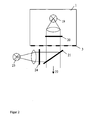
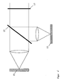
Die in der Ebene (3) vorhandene Lichtverteilung wird über den Strahlteiler (7) und das Objektiv (5) auf oder in das zu untersuchende Objekt (10) projiziert. Dabei sind die Ebene (3) und die nominale Objektebene (9) zueinander konjugiert. Der Strahlteiler (7) kann ein halbdurchlässiger Spiegel oder auch ein dichroitischer Strahlteiler sein. Multi-Band Strahlteiler können ebenfalls eingesetzt werden. Die auf bzw. in die Probe projizierte Lichtverteilung wird nun über ein Objektiv und weitere Zwischenoptiken auf die Detektionseinheit (11) abgebildet. Die Ebene (13) ist dabei eine Bildebene oder Zwischenbildebene, welche konjugiert zu den Ebenen (9) und (3) ist. Die Lage der Fokusebene innerhalb des Objektes kann mittels einer Fokussiereinrichtung eingestellt werden, wobei dies gewöhnlich durch eine axiale Bewegung des Objektives (5) oder der Probe realisiert wird. In einem Mikroskopsystem ist es vorteilhaft, wenn die Ebene (3) mit der zu projizierenden Lichtverteilung konjugiert zur Ebene der Leuchtfeldblende ist. Innerhalb der Detektionseinheit (11) kann sich dabei ein Ortsaufgelöster Detektor, wie zum Beispiel ein CCD oder ein CMOS-Sensor befinden. Alternativ dazu kann die Einheit (11) auch das sich in Ebene (13) befindliche Bild weiter auf einen oder mehrere Detektoren abbilden.The light distribution present in the plane (3) is projected via the beam splitter (7) and the objective (5) onto or into the object (10) to be examined. The plane (3) and the nominal object plane (9) are conjugate to each other. The beam splitter (7) may be a semi-transparent mirror or a dichroic beam splitter. Multi-band beam splitters can also be used. The light distribution projected onto or into the sample is now imaged onto the detection unit (11) via a lens and further intermediate optics. The plane (13) is an image plane or intermediate image plane which is conjugate to the planes (9) and (3). The position of the focal plane within the object can be adjusted by means of a focusing device, which is usually realized by an axial movement of the objective (5) or the sample. In a microscope system, it is advantageous if the plane (3) with the light distribution to be projected is conjugate to the plane of the field diaphragm. Within the detection unit (11) may be located a spatially resolved detector, such as a CCD or a CMOS sensor. Alternatively, the unit (11) Also, the image located in plane (13) continue to image on one or more detectors.
Die Maske in Ebene (3) hat Bereiche, welche besonders stark reflektieren und dazu komplementäre Bereiche mit besonders hoher Transmission. Eine solche Maske kann nicht nur binäre Strukturen sondern auch kontinuierliche Verteilungen enthalten. In Ebene (3) kann sich eine strukturierte Spiegeloberfläche befinden. Dabei werden von beiden Lichtquellen zueinander komplementäre Lichtverteilungen durch Transmission (Lichtquelle (19)) und durch Reflexion (Lichtquelle (23)) an der Maskenstruktur in Ebene (3) erzeugt.
Es ist hervorzuheben, dass eine solche Anordnung zwei verschiedene Beleuchtungsverteilungen zur Verfügung stellt, welche die simultane oder zeitsequentielle Projektion von zwei Strukturen bzw. zwei verschiedenen Phasenlagen derselben Struktur ohne jegliche beweglichen mechanische Elemente ermöglicht. Dies führt zu Geschwindigkeitsvorteilen und auch zu reduziertem Justieraufwand bei der Implementierung des erfindungsgemäßen Verfahrens und ist ein wesentlicher Vorteil gegenüber dem Stand der Technik.
The mask in plane (3) has areas which reflect particularly strongly and complementary areas with particularly high transmission. Such a mask can contain not only binary structures but also continuous distributions. In level (3) there may be a structured mirror surface. In this case, complementary light distributions from both light sources are generated by transmission (light source (19)) and by reflection (light source (23)) on the mask structure in plane (3).
It should be emphasized that such an arrangement provides two different illumination distributions, which allow the simultaneous or time-sequential projection of two structures or two different phase positions of the same structure without any moving mechanical elements. This leads to speed advantages and also to reduced adjustment effort in the implementation of the method according to the invention and is a significant advantage over the prior art.
Bei zeitsequentiellem Betrieb emittiert entweder die Lichtquelle (19) oder die Quelle (23) Licht, wobei die Aufnahmen der Abbildung der Probe mittels der Detektionseinheit (11) dazu synchronisiert sind.In time-sequential operation, either the light source (19) or the source (23) emits light, with the images of the image of the sample being synchronized by means of the detection unit (11).
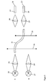
In einer weiteren Ausgestaltung der Erfindung werden beide Lichtverteilungen bzw. Beleuchtungsstrukturen zeitgleich abgestrahlt. Zu einer Kodierung der beiden Verteilungen kann dazu die Polarisation des abgestrahlten Lichtes oder seine spektrale Charakteristik genutzt werden. Hierzu werden die beiden optionalen Polarisationsfilter bzw. Spektralfilter (20) und (24) in
Die als Ausführungsbeispiel dargestellte Anordnung zur zeitsimultanen und durch Polarisation oder spektrale Charakteristik kodierten Abstrahlung von zwei komplementären Beleuchtungsstrukturen hat zusätzliche Geschwindigkeitsvorteile und ermöglicht die Erzeugung von Schnittbildern in Echtzeit, wie es insbesondere bei der Materialmikroskopie im Auflichtbetrieb und zur Konstruktion von Oberflächenvermessungssystemen für mikroskopische und makroskopische Objekte wünschenswert ist.The arrangement shown as an exemplary embodiment for time-simulated and coded by polarization or spectral characteristic radiation of two complementary illumination structures has additional speed advantages and allows the generation of sectional images in real time, as in particular in the material microscopy in incident light mode and the construction of surface surveying systems for microscopic and macroscopic objects desirable is.
Dies hat zwei Hauptvorteile: erstens wird nur ein Exemplar einer Lichtquelle benötigt, was die Kosten senkt und die gleiche spektrale Verteilung in beiden Projektionsschritten sicher stellt. Zweitens können die Ausgänge (19) und (23) als fest justierte Punktlichtquellen fungieren, auf welche die restliche Optik der Projektionseinheit justiert ist und bleibt. Dies reduziert den Justieraufwand.This has two main advantages: first, only one copy of a light source is needed, which reduces costs and ensures the same spectral distribution in both projection steps. Second, the outputs (19) and (23) can act as fixed point light sources to which the remaining optics of the projection unit is and remains adjusted. This reduces the adjustment effort.
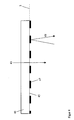
In
In
Wenn die beiden projizierten Lichtverteilungen durch Polarisation oder spektral entsprechend
If the two projected light distributions by polarization or spectrally corresponding
Der Verfahrensablauf kann wie folgt zusammengefasst werden:The procedure can be summarized as follows:
In einem ersten Schritt können eine oder mehrere der später auch zur Schnittbildgenerierung verwendeten Beleuchtungsstrukturen auf ein bekanntes Kalibrierobjekt projiziert werden. Aus diesen Daten oder den Bilddaten zur Schnittbildberechnung selbst werden die lokale Phase der projizierten Struktur und optional die lokale Strukturperiode und / oder die Intensitätsverteilung der Projektionsschritte für jeden Ort auf Detektor bestimmt. Die Kalibriermessung kann eingespart werden, wenn die lokale Phase und Gitterfrequenz der projizierten Beleuchtungsstruktur aus den im späteren Prozessverlauf aufgenommenen Bilddaten bestimmt werden kann.In a first step, one or more of the illumination structures that are also used later for generating the slice image can be projected onto a known calibration object. From this data or the image data for the sectional image calculation itself, the local phase of the projected structure and optionally the local structure period and / or the intensity distribution of the projection steps for each location on the detector are determined. The calibration measurement can be saved if the local phase and grid frequency of the projected illumination structure can be determined from the image data taken in the later course of the process.
In weiteren Prozessschritten, welche beliebig oft und für verschiedene Wellenlängen und verschiedene axiale Positionen der Probe wiederholt werden können, werden jeweils zwei Projektionsstrukturen auf die Probe projiziert und mit Hilfe der lokalen Phasen und Gitterfrequenz der Beleuchtungsverteilung auf dem Detektor ein optisches Schnittbild berechnet. Die Implementierungen zur strukturierten Beleuchtung entsprechend dem Stand der Technik benötigen mindestens drei Projektionsschritte zur Erzeugung eines Schnittbildes und sind dadurch weniger effizient. Zusätzlich wurden erfindungsgemäße Anordnungen vorgeschlagen, welche die Projektion der beiden Beleuchtungsstrukturen ohne bewegliche mechanische Elemente und in einer Ausführung sogar zeitgleich ermöglichen. Die Selektion der projizierten Lichtverteilung kann durch elektronische Steuerung von Lichtquellen und /oder optischen Schaltern erfolgen. Weitere ausgestaltende Anordnungen ermöglichen den Wechsel der Abbildungswellenlänge ohne Bewegung von mechanischen Elementen.In further process steps, which can be repeated as often and for different wavelengths and different axial positions of the sample, two projection structures are projected onto the sample and an optical sectional image is calculated on the detector with the aid of the local phases and grid frequency of the illumination distribution. The prior art structured illumination implementations require at least three projection steps to produce a cross-sectional image and are thus less efficient. In addition, arrangements according to the invention have been proposed which allow the projection of the two lighting structures without moving mechanical elements and in one embodiment even at the same time. The selection of the projected light distribution can be done by electronic control of light sources and / or optical switches. Other configurations make it possible to change the imaging wavelength without moving mechanical elements.
Eine Kalibriermessung zur Bestimmung der lokalen Phasen und Gitterfrequenzen muss nur bei einer Änderung am optischen System, wie zum Beispiel einem Objektivwechsel und eventuell der erstmaligen Nutzung einer neuen Wellenlänge vorgenommen werden oder kann entfallen, wenn die Bestimmung aus den aufgenommenen Bilddaten in ausreichender Qualität möglich ist und die hierzu erforderliche Rechenzeit toleriert werden kann.A calibration measurement to determine the local phases and grating frequencies must be made only with a change in the optical system, such as a lens change and possibly the first use of a new wavelength or may be omitted if the determination of the recorded image data in sufficient quality is possible and the required computing time can be tolerated.
-
[1] Marvin Minsky, "Microscopy Apparatus",
US patent 3013467, 1961 US Pat. No. 3,013,467, 1961 -
[2]
M. A. A. Neil, R. Juskaitis, and T. Wilson: "Method of Obtaining Optical Sectioning by using Structured Light in a conventional microscope", Optics Letters, Vol. 22, No. 24, p. 1905, 1997 MAA Neil, R. Juskaitis, and T. Wilson: "Method of Obtaining Optical Sectioning by Using Structured Light in a Conventional Microscope", Optics Letters, Vol. 24, p. 1905, 1997 -
[3] Wilson et al., "Microscopy Imaging Apparatus and Method",
US patent 6376818, 2002 US patent 6376818, 2002 -
[4] Gerstner et al., "Assembly for Increasing the Depth Discrimination of an Optical Imaging System",
US patent 681945 B2, 2004 US patent 681945 B2, 2004 -
[5] Gerstner et al., "Assembly for Increasing the Depth Discrimination of an Optical Imaging System", Internationales Patent
WO02/12945, 2002 WO02 / 12945, 2002 -
[6]
M.A.A. Neil et al., "Real Time 3D Fluorescence Microscopy by Two-Beam Interference Illumination", Optics Communications, 153, 1998 MAA Neil et al., Real Time 3D Fluorescence Microscopy by Two-Beam Interference Illumination, Optics Communications, 153, 1998 -
[7]
Schaefer, " Structured illumination microscopy: artefact analysis and reduction utilizing a parameter optimization approach", Journal of Microscopy 216 (2), 165-174, 2004 Schaefer, "Structured illumination microscopy: artifact analysis and reduction using a parameter optimization approach," Journal of Microscopy 216 (2), 165-174, 2004 -
[8] Wilson et al., "Confocal Microscopy Apparatus and Method",
US patent 6687052, 2004 US patent 6687052, 2004 -
[9] Ralf Wolleschensky, "Verfahren und Anordnung zur Tiefenaufgelösten optischen Erfassung einer Probe", Europäisches Patent
EP 1420281, 2004 EP 1420281, 2004 -
[10] Mark Hopkins, "Multi-Spectral Two-Dimensional Imaging Spectrometer", US patent
US5926283 US5926283 -
[11] Colin G. Morgan, "Optical Sensor for imaging an object", United States Patent
US5381236 US5381236 -
[12]
Chenggen Quan et al., "Shape measurement by use of liquid-crystal display fringe projection with two-step phase shifting", Applied Optics, Vol, 42, No. 13, 2003, 2329-2335 Chenggen Quan et al., "Shape measurement by use of liquid-crystal display fringe projection with two-step phase shifting", Applied Optics, Vol, 42, no. 13, 2003, 2329-2335 -
[13]
S.E.D. Webb et al, "A wide field timeßdomain fluorescence lifetime imaging microscope with optical sectioning", Review of Scientific Instruments, Vol. 73, No. 4, 2002, 1898-1907 SED Webb et al, "A wide field time domain fluorescence lifetime imaging microscope with optical sectioning", Review of Scientific Instruments, Vol. 73, no. 4, 2002, 1898-1907 -
[14]
L.G. Kryewina and M.K. Kim, "Single-exposure optical sectioning by color structured illumination microscopy", Optics Letters, Vol. 31, No. 4, 2006, 477-479 LG Kryewina and MK Kim, "Single-exposure optical sectioning by color structured illumination microscopy", Optics Letters, Vol. 4, 2006, 477-479
Claims (9)
- Arrangement for the generation of optical section images, consisting of an illumination unit (1), an optical arrangement (5) for the imaging of the sample onto at least one spatially resolving detector (11), a focusing means as well as a signal processing unit for the implementation of a method for the optical reproduction with depth discrimination, characterized in that
the illumination unit creates by illumination of a mask with light sources (19; 23) only two complementary illumination distributions each in or on the sample, the illumination distributions have a periodicity in at least one spatial direction, the sample plane in which the illumination distribution is created is conjugated with respect to the plane of the corresponding spatially resolving detector (11), and the two light distributions created by the illumination light in or on the sample from the interaction with the illumination light are registered time-sequentially or time-simultaneously by the one or more spatially resolving detectors (11) and fed to the signal processing unit for the calculation and generation of an optical section image S(x,y),
wherein by means of a calibration step the local phase of the periodic structure α(x,y) and the local grating frequency g(x,y) can be determined, and for the calculation of the section image S(x,y) from the two recorded illumination distributions differences between the illumination distributions and/or differences between spatial properties within the two intensity distributions are used, wherein the spatial properties are partial derivatives or gradients within the illumination distributions, and the section image S(x,y) to be determined is calculated by means of the equation

with
and
wherein I1(x,y) and I2(x,y) are the complementary intensity distributions measured on the detector (11). - Arrangement for the generation of optical section images according to claim 1,
characterized in that
the light distributions created by the illumination light in or on the sample from the interaction with the illumination light are registered time-simultaneously by the one or more spatially resolving detectors (11) and fed to the signal processing unit for the calculation and generation of an optical section image, wherein further the two illumination distributions are simultaneously projected and detected, wherein the light used for both projections is different with respect to its polarization and/or spectral composition, wherein these different properties of the illumination light lead to different properties of the light distributions simultaneously emitted from the sample and these properties of the light emitted from the sample are used to separate the illumination distributions on the detection side. - Arrangement for the generation of optical section images according to claim 1 or 2,
characterized in that
for the calibration of the light distribution registered on one or more detectors (11) there is a calibration object (53), which is inserted instead of the sample or is mounted in the optical system in an image plane conjugated with the sample or can be brought into position, wherein the calibration object (53) has homogeneous and/or known sample properties and is preferably flat. - Arrangement for the generation of optical section images according to claim 1 or 2,
characterized in that
the one or more spatially resolving detectors (11) detect fluorescence light emitted by the sample and/or luminescence light generated in the sample, wherein a temporal modulation of the excitation by means of the illumination unit is implemented in combination with a synchronous or time-resolved detection, and the fluorescence lifetime and/or luminescence lifetime is determined. - Arrangement for the generation of optical section images according to claim 1 or 2,
characterized in that
the illumination unit (1) for the generation of the illumination distributions in or on the sample uses a mask in transmission and/or reflection or a phase mask or a pixelated element, or the illumination pattern is produced by the interference of plane waves. - Arrangement for the generation of optical section images according to claim 1 or 2,
characterized in that
the illumination unit (1) generates two illumination distributions which are phase-shifted relative to one another by 180 degrees. - Arrangement for the generation of optical section images according to claim 1 or 2,
characterized in that
the two illumination distributions are generated within the illumination unit (1) by means of front illumination or back illumination of a mask structure. - Arrangement for the generation of optical section images according to claim 1 or 2,
characterized in that
the two illumination distributions are configured within the illumination unit (1) by means of electronic switching of light sources and/or the switching of optical fiber switches. - Arrangement for the generation of optical section images according to claim 1 or 2,
characterized in that
the arrangement allows a switching of the spectral composition of the light emitted by the illumination unit and/or the light registered by the at least one spatially resolving detector (11).
Applications Claiming Priority (2)
| Application Number | Priority Date | Filing Date | Title |
|---|---|---|---|
| DE102007018048A DE102007018048A1 (en) | 2007-04-13 | 2007-04-13 | Method and arrangement for optical imaging with depth discrimination |
| PCT/EP2008/054390 WO2008125605A2 (en) | 2007-04-13 | 2008-04-11 | Method and assembly for optical reproduction with depth discrimination |
Publications (2)
| Publication Number | Publication Date |
|---|---|
| EP2137488A2 EP2137488A2 (en) | 2009-12-30 |
| EP2137488B1 true EP2137488B1 (en) | 2012-08-08 |
Family
ID=39642649
Family Applications (1)
| Application Number | Title | Priority Date | Filing Date |
|---|---|---|---|
| EP08736106A Active EP2137488B1 (en) | 2007-04-13 | 2008-04-11 | Method and assembly for optical reproduction with depth discrimination |
Country Status (5)
| Country | Link |
|---|---|
| US (1) | US7977625B2 (en) |
| EP (1) | EP2137488B1 (en) |
| CN (1) | CN101680749B (en) |
| DE (1) | DE102007018048A1 (en) |
| WO (1) | WO2008125605A2 (en) |
Cited By (1)
| Publication number | Priority date | Publication date | Assignee | Title |
|---|---|---|---|---|
| DE102017205474A1 (en) * | 2017-03-31 | 2018-10-04 | Robert Bosch Gmbh | Device, for example for a LIDAR sensor, for generating variable interference patterns and method for operating such a device |
Families Citing this family (78)
| Publication number | Priority date | Publication date | Assignee | Title |
|---|---|---|---|---|
| WO2010077205A1 (en) * | 2009-01-05 | 2010-07-08 | Ge Healthcare Bio-Sciences Corp | A system and method for simultaneously obtaining a plurality of images in an imaging system |
| DE102009009950A1 (en) | 2009-02-23 | 2010-10-21 | Confovis Gmbh | Arrangement for recovering three-dimensional object data in e.g. industrial application, has execution device for executing relative motion of structured illuminated sample plane that is bent with respect to direction of relative motion |
| EP2223650A1 (en) * | 2009-02-25 | 2010-09-01 | The Provost, Fellows and Scholars of the College of the Holy and Undivided Trinity of Queen Elizabeth near Dublin | Method and apparatus for imaging tissue topography |
| GB0907965D0 (en) * | 2009-05-08 | 2009-06-24 | King S College London | Imaging system |
| ES2607052T3 (en) | 2009-06-17 | 2017-03-29 | 3Shape A/S | Focus scanning apparatus |
| EP2314200B1 (en) * | 2009-10-21 | 2016-01-13 | SIS AG, Surgical Instrument Systems | Method and device for measuring a cornea |
| US8414124B2 (en) | 2009-10-21 | 2013-04-09 | Sis Ag, Surgical Instrument Systems | Device and method for measuring a cornea |
| ES2364916B1 (en) * | 2010-03-05 | 2012-09-04 | Consejo Superior De Investigaciones Científicas (Csic) | INSTRUMENT FOR THE IMPLEMENTATION OF WIDE FIELD IMAGES TO DIFFERENT DEPTHS OF A SPECIMEN |
| WO2011119678A2 (en) | 2010-03-23 | 2011-09-29 | California Institute Of Technology | Super resolution optofluidic microscopes for 2d and 3d imaging |
| DE102010016598A1 (en) * | 2010-04-23 | 2011-10-27 | Leica Microsystems Cms Gmbh | A method of inspecting a sample containing fluorescent dyes by means of a microscope |
| JP2011229603A (en) * | 2010-04-26 | 2011-11-17 | Fujifilm Corp | Endoscopic system |
| JP2011229625A (en) * | 2010-04-26 | 2011-11-17 | Fujifilm Corp | Endoscopic system |
| US10010268B2 (en) * | 2010-09-15 | 2018-07-03 | Olympus Corporation | Endoscope apparatus |
| EP2437027A3 (en) | 2010-10-03 | 2012-05-30 | Confovis GmbH | Device and method for three dimensional optical mapping of a sample |
| US9569664B2 (en) * | 2010-10-26 | 2017-02-14 | California Institute Of Technology | Methods for rapid distinction between debris and growing cells |
| CN103154662A (en) | 2010-10-26 | 2013-06-12 | 加州理工学院 | Scanning projective lensless microscope system |
| US9643184B2 (en) * | 2010-10-26 | 2017-05-09 | California Institute Of Technology | e-Petri dishes, devices, and systems having a light detector for sampling a sequence of sub-pixel shifted projection images |
| CN103534627A (en) | 2011-03-03 | 2014-01-22 | 加州理工学院 | Light guided pixel |
| DE102011017046A1 (en) * | 2011-04-14 | 2012-10-18 | Till Photonics Gmbh | Switchable microscope arrangement with multiple detectors |
| JP5839907B2 (en) * | 2011-09-15 | 2016-01-06 | キヤノン株式会社 | Image processing apparatus and image processing method |
| DE102011114932A1 (en) | 2011-10-06 | 2013-04-11 | Hommel-Etamic Gmbh | Method for determining contour of upper surface of object along measuring section, involves varying focusing of microscope objective relative to upper surface along measuring axis over scan range at measuring paths |
| US8340456B1 (en) * | 2011-10-13 | 2012-12-25 | General Electric Company | System and method for depth from defocus imaging |
| US9245445B2 (en) * | 2012-02-21 | 2016-01-26 | Ricoh Co., Ltd. | Optical target detection |
| DE102012007045B4 (en) | 2012-04-05 | 2023-03-16 | Carl Zeiss Microscopy Gmbh | Apparatus and method for microscopy |
| DE102012009836A1 (en) * | 2012-05-16 | 2013-11-21 | Carl Zeiss Microscopy Gmbh | Light microscope and method for image acquisition with a light microscope |
| AU2013202804A1 (en) | 2012-06-14 | 2014-01-16 | Gen-Probe Incorporated | Use of a fluorescent material to detect failure or deteriorated performance of a fluorometer |
| DE102012017920B4 (en) * | 2012-09-11 | 2023-11-30 | Carl Zeiss Microscopy Gmbh | Optical arrangement and light microscope |
| DE102012017922B4 (en) | 2012-09-11 | 2024-03-14 | Carl Zeiss Microscopy Gmbh | Optical arrangement and light microscope |
| JP6128822B2 (en) * | 2012-12-05 | 2017-05-17 | オリンパス株式会社 | Optical device |
| JP6161276B2 (en) * | 2012-12-12 | 2017-07-12 | キヤノン株式会社 | Measuring apparatus, measuring method, and program |
| US20140235948A1 (en) * | 2013-02-19 | 2014-08-21 | The Board Of Trustees Of The Leland Stanford Junior University | Method for single-fiber microscopy using intensity-pattern sampling and optimization-based reconstruction |
| US9740166B2 (en) | 2013-03-06 | 2017-08-22 | Hamamatsu Photonics K.K. | Fluorescence receiving apparatus and fluorescence receiving method |
| DE102013103333A1 (en) * | 2013-04-03 | 2014-10-09 | Karl Storz Gmbh & Co. Kg | Camera for recording optical properties and room structure properties |
| DE102013218231A1 (en) * | 2013-09-11 | 2015-03-12 | Sirona Dental Systems Gmbh | Optical system for generating a time-varying pattern for a confocal microscope |
| US9618450B2 (en) * | 2013-09-27 | 2017-04-11 | Ecolab USA, Inc. | Multi-channel fluorometric sensor and method of using same |
| ES2881544T3 (en) * | 2013-10-01 | 2021-11-29 | Renishaw Plc | Method of manufacturing an electronic component |
| EP2879004A1 (en) * | 2013-12-02 | 2015-06-03 | IMEC vzw | Apparatus and method for performing in-line lens-free digital holography of an object |
| US10010387B2 (en) | 2014-02-07 | 2018-07-03 | 3Shape A/S | Detecting tooth shade |
| JP6378931B2 (en) * | 2014-05-21 | 2018-08-22 | 浜松ホトニクス株式会社 | Microscope device and image acquisition method |
| DE102014009372A1 (en) * | 2014-06-23 | 2015-12-24 | Fraunhofer-Gesellschaft zur Förderung der angewandten Forschung e.V. | Arrangement for determining properties and / or parameters of a sample and / or at least one layer formed on or on a surface of a sample |
| US9675430B2 (en) | 2014-08-15 | 2017-06-13 | Align Technology, Inc. | Confocal imaging apparatus with curved focal surface |
| DE102014113258A1 (en) * | 2014-09-15 | 2016-03-17 | Carl Zeiss Ag | Method for generating a result image and optical device |
| CN104296660A (en) * | 2014-11-05 | 2015-01-21 | 哈尔滨工业大学 | Microcosmic smooth free-form surface sample measurement device and method based on structured light method |
| CN104570315B (en) * | 2014-12-30 | 2017-06-27 | 中国科学院西安光学精密机械研究所 | A kind of color three dimension chromatography micro imaging system and method based on structured illumination |
| DE102015208080A1 (en) * | 2015-04-30 | 2016-11-03 | Carl Zeiss Microscopy Gmbh | Method for reflection correction of images and related devices |
| DE102015209402A1 (en) * | 2015-05-22 | 2016-11-24 | Sirona Dental Systems Gmbh | Device for optical 3D measurement of an object |
| DE102015210016A1 (en) | 2015-06-01 | 2016-12-01 | Carl Zeiss Microscopy Gmbh | Method for determining a spatially resolved height information of a sample with a wide field microscope and a wide field microscope |
| DE102015108912A1 (en) | 2015-06-05 | 2016-12-08 | Carl Zeiss Microscopy Gmbh | Apparatus and method for detecting surface topographies |
| DE102015217091B4 (en) | 2015-09-07 | 2017-05-11 | Fraunhofer-Gesellschaft zur Förderung der angewandten Forschung e.V | Arrangement for determining the achievable adhesive strength before formation of a material-locking connection on a surface of a joining partner |
| LU93022B1 (en) * | 2016-04-08 | 2017-11-08 | Leica Microsystems | Method and microscope for examining a sample |
| US10725279B2 (en) * | 2016-04-08 | 2020-07-28 | Arizona Board Of Regents On Behalf Of The University Of Arizona | Systems and methods for extended depth-of-field microscopy |
| JP2017207329A (en) * | 2016-05-17 | 2017-11-24 | Juki株式会社 | Illumination device and inspection device |
| DE102016117803A1 (en) | 2016-09-21 | 2018-03-22 | Leica Microsystems Cms Gmbh | Microscope illumination arrangement for structured illumination |
| CN110381812B (en) * | 2016-12-30 | 2022-08-30 | 巴科股份有限公司 | System and method for camera calibration |
| DE102017213549B3 (en) * | 2017-08-04 | 2018-09-27 | Ifm Electronic Gmbh | Light section sensor and method for operating a light section sensor |
| CN107621463B (en) * | 2017-10-16 | 2024-03-22 | 苏州微景医学科技有限公司 | Image reconstruction method and device and microscopic imaging device |
| DE102017009804A1 (en) * | 2017-10-20 | 2019-04-25 | Vermicon Ag | Method for evaluating microscopic samples and apparatus for carrying out this method |
| EP3486706A1 (en) * | 2017-11-16 | 2019-05-22 | Carl Zeiss Microscopy GmbH | Functional module and microscope equipped with the same |
| CN111656246B (en) * | 2018-01-02 | 2022-07-29 | 伦敦大学国王学院 | Method and system for positioning microscopy, computer readable storage medium |
| TWI699559B (en) * | 2018-01-16 | 2020-07-21 | 美商伊路米納有限公司 | Structured illumination imaging system and method of creating a high-resolution image using structured light |
| CN108303373B (en) * | 2018-02-01 | 2021-01-22 | 京东方科技集团股份有限公司 | Device for detecting vanishing grade and control method thereof |
| JP7099367B2 (en) * | 2019-03-06 | 2022-07-12 | 株式会社ダイフク | Inspection system |
| EP3938763A4 (en) | 2019-03-14 | 2022-12-07 | Applied Materials, Inc. | Identifying fiducial markers in microscope images |
| US11255785B2 (en) * | 2019-03-14 | 2022-02-22 | Applied Materials, Inc. | Identifying fiducial markers in fluorescence microscope images |
| CN110207609B (en) * | 2019-04-25 | 2021-03-23 | 合刃科技(武汉)有限公司 | Three-dimensional imaging method and device of active light based on multiple spectrums and storage medium |
| CN110057743A (en) * | 2019-05-06 | 2019-07-26 | 西安交通大学 | The label-free cell three-dimensional Morphology observation method of blood film based on optic virtual dyeing |
| CN110233973B (en) * | 2019-05-28 | 2021-01-15 | 怀光智能科技(武汉)有限公司 | Slide scanner light source |
| DE102019212520A1 (en) * | 2019-08-21 | 2021-02-25 | Carl Zeiss Smt Gmbh | Diffractive optical element for a test interferometer |
| KR102116232B1 (en) * | 2019-11-12 | 2020-05-28 | (주)로고스바이오시스템스 | Sample detection device and sample detection method by using the same |
| CN110824690B (en) * | 2019-11-13 | 2020-09-29 | 河北工程大学 | Holographic microscopic equipment for judicial marking detection based on big data |
| CN111356896B (en) | 2020-02-24 | 2021-01-12 | 长江存储科技有限责任公司 | System and method for semiconductor chip surface topography metrology |
| WO2021168611A1 (en) | 2020-02-24 | 2021-09-02 | Yangtze Memory Technologies Co., Ltd. | Systems and methods for semiconductor chip surface topography metrology |
| CN111386441B (en) | 2020-02-24 | 2021-02-19 | 长江存储科技有限责任公司 | System for measuring surface topography of semiconductor chip |
| WO2021168612A1 (en) | 2020-02-24 | 2021-09-02 | Yangtze Memory Technologies Co., Ltd. | Systems and methods for semiconductor chip surface topography metrology |
| DE102021110263A1 (en) | 2021-04-22 | 2022-10-27 | MAX-PLANCK-Gesellschaft zur Förderung der Wissenschaften e.V. | Method and illumination device of adaptive optics in reflection microscopy |
| CN113252633B (en) * | 2021-07-14 | 2021-10-12 | 季华实验室 | Quality control detection method and standard disc of liquid phase chip analyzer |
| CN115061270B (en) * | 2022-05-30 | 2024-01-16 | 中国人民解放军国防科技大学 | Inclination mode telescopic microscopic combined imaging method |
| CN116892883B (en) * | 2023-09-11 | 2023-11-28 | 深圳市深视智能科技有限公司 | Inclination displacement sensor and optical anti-shake system |
Family Cites Families (15)
| Publication number | Priority date | Publication date | Assignee | Title |
|---|---|---|---|---|
| US3013467A (en) | 1957-11-07 | 1961-12-19 | Minsky Marvin | Microscopy apparatus |
| GB9102903D0 (en) * | 1991-02-12 | 1991-03-27 | Oxford Sensor Tech | An optical sensor |
| JP3066874B2 (en) | 1997-04-04 | 2000-07-17 | イシス イノヴェーション リミテッド | Microscope imaging apparatus and method |
| AU731476C (en) | 1997-07-12 | 2001-12-06 | Roper Scientific, Inc. | Multi-spectral two-dimensional imaging spectrometer |
| GB9901365D0 (en) | 1999-01-22 | 1999-03-10 | Isis Innovations Ltd | Confocal microscopy apparatus and method |
| JP4429431B2 (en) * | 1999-10-21 | 2010-03-10 | オリンパス株式会社 | Optical device |
| JP2001330555A (en) * | 2000-05-19 | 2001-11-30 | Yokogawa Electric Corp | Optical scanner and tomographic image acquiring apparatus using the same |
| US6628381B1 (en) * | 2000-06-20 | 2003-09-30 | Applied Materials, Inc. | Optical inspection method and apparatus utilizing a collection angle design |
| DE10038527A1 (en) | 2000-08-08 | 2002-02-21 | Zeiss Carl Jena Gmbh | Arrangement to increase depth discrimination in optical imaging systems |
| DE10118463A1 (en) * | 2001-04-07 | 2002-10-10 | Zeiss Carl Jena Gmbh | Depth-resolved optical imaging method for use in biological scanning microscopy, uses phase or frequency modulation of the imaging light |
| GB0200819D0 (en) | 2002-01-15 | 2002-03-06 | Cole Polytechnique Federale De | Microscopy imaging apparatus and method for generating an image |
| DE10204430A1 (en) * | 2002-02-04 | 2003-08-07 | Zeiss Carl | Stereo microscopy method and stereo microscopy system |
| DE10254139A1 (en) | 2002-11-15 | 2004-05-27 | Carl Zeiss Jena Gmbh | Method and arrangement for the depth-resolved optical detection of a sample |
| US7041998B2 (en) * | 2003-03-24 | 2006-05-09 | Photon Dynamics, Inc. | Method and apparatus for high-throughput inspection of large flat patterned media using dynamically programmable optical spatial filtering |
| US7115848B1 (en) * | 2004-09-29 | 2006-10-03 | Qioptiq Imaging Solutions, Inc. | Methods, systems and computer program products for calibration of microscopy imaging devices |
-
2007
- 2007-04-13 DE DE102007018048A patent/DE102007018048A1/en not_active Ceased
-
2008
- 2008-04-11 WO PCT/EP2008/054390 patent/WO2008125605A2/en active Application Filing
- 2008-04-11 EP EP08736106A patent/EP2137488B1/en active Active
- 2008-04-11 US US12/450,759 patent/US7977625B2/en active Active
- 2008-04-11 CN CN2008800185091A patent/CN101680749B/en active Active
Cited By (1)
| Publication number | Priority date | Publication date | Assignee | Title |
|---|---|---|---|---|
| DE102017205474A1 (en) * | 2017-03-31 | 2018-10-04 | Robert Bosch Gmbh | Device, for example for a LIDAR sensor, for generating variable interference patterns and method for operating such a device |
Also Published As
| Publication number | Publication date |
|---|---|
| WO2008125605A2 (en) | 2008-10-23 |
| DE102007018048A1 (en) | 2008-10-16 |
| CN101680749A (en) | 2010-03-24 |
| CN101680749B (en) | 2013-07-10 |
| US7977625B2 (en) | 2011-07-12 |
| EP2137488A2 (en) | 2009-12-30 |
| US20100108873A1 (en) | 2010-05-06 |
| WO2008125605A3 (en) | 2009-02-26 |
Similar Documents
| Publication | Publication Date | Title |
|---|---|---|
| EP2137488B1 (en) | Method and assembly for optical reproduction with depth discrimination | |
| DE102006007172B4 (en) | Method and arrangement for rapid, spatially resolved, areal, spectroscopic analysis, or for spectral imaging or for 3D detection by means of spectroscopy | |
| EP1248132B1 (en) | Method and arrangement for depth resolving optical detection of a probe | |
| DE102011114500B4 (en) | microscope device | |
| EP2860566B1 (en) | High resolution scanning microscopy | |
| EP1264169B1 (en) | Improvement of spectral and/or spatial resolution in a laser scanning microscope | |
| WO2013171309A1 (en) | Light microscope and method for image recording using a light microscope | |
| EP2592461B1 (en) | Microscopic device and method for three-dimensional localization of punctiform objects in a sample | |
| EP2038690A2 (en) | Method and device for producing an image of a thin layer of an object | |
| EP3056934B1 (en) | Measuring head of an endoscopic device and method of inspecting and measuring an object | |
| DE102013016368A1 (en) | Light microscope and microscopy method for examining a microscopic sample | |
| EP3058414B1 (en) | Scanning microscope and method for determining the point spread function (psf) of a scanning microscope | |
| DE19626261A1 (en) | IC pattern and metal surface test object observation differential interference microscope | |
| DE102004053730B4 (en) | Method and arrangement for the suppression of false light | |
| EP3948392B1 (en) | Method and device for detecting movements of a sample with respect to a lens | |
| DE10155002A1 (en) | Depth-resolved optical imaging method for use in biological scanning microscopy, uses phase or frequency modulation of the imaging light | |
| DE102020209889A1 (en) | Microscope and method for microscopic imaging with variable illumination | |
| WO2016193037A1 (en) | Method for determining spatially resolved height information of a sample by means of a wide-field microscope, and wide-field microscope | |
| DE10118463A1 (en) | Depth-resolved optical imaging method for use in biological scanning microscopy, uses phase or frequency modulation of the imaging light | |
| DE102007047468A1 (en) | Method and arrangement for optically detecting an illuminated sample | |
| WO2015044035A1 (en) | Confocal light microscope and method for examining a sample using a confocal light microscope | |
| EP3953684A1 (en) | Light sheet microscope and method for determining the refractive indices of objects in the specimen space | |
| DE102015108912A1 (en) | Apparatus and method for detecting surface topographies | |
| EP1794572B1 (en) | Method of operating an interferometric system with a reference element with one or multiple mirrored zones | |
| DE102018126009A1 (en) | Method and microscope for determining the thickness of a cover or supporting glass |
Legal Events
| Date | Code | Title | Description |
|---|---|---|---|
| PUAI | Public reference made under article 153(3) epc to a published international application that has entered the european phase |
Free format text: ORIGINAL CODE: 0009012 |
|
| 17P | Request for examination filed |
Effective date: 20091102 |
|
| AK | Designated contracting states |
Kind code of ref document: A2 Designated state(s): AT BE BG CH CY CZ DE DK EE ES FI FR GB GR HR HU IE IS IT LI LT LU LV MC MT NL NO PL PT RO SE SI SK TR |
|
| 17Q | First examination report despatched |
Effective date: 20100112 |
|
| GRAP | Despatch of communication of intention to grant a patent |
Free format text: ORIGINAL CODE: EPIDOSNIGR1 |
|
| DAX | Request for extension of the european patent (deleted) | ||
| GRAS | Grant fee paid |
Free format text: ORIGINAL CODE: EPIDOSNIGR3 |
|
| GRAA | (expected) grant |
Free format text: ORIGINAL CODE: 0009210 |
|
| AK | Designated contracting states |
Kind code of ref document: B1 Designated state(s): AT BE BG CH CY CZ DE DK EE ES FI FR GB GR HR HU IE IS IT LI LT LU LV MC MT NL NO PL PT RO SE SI SK TR |
|
| REG | Reference to a national code |
Ref country code: GB Ref legal event code: FG4D Free format text: NOT ENGLISH |
|
| REG | Reference to a national code |
Ref country code: CH Ref legal event code: EP Ref country code: AT Ref legal event code: REF Ref document number: 569997 Country of ref document: AT Kind code of ref document: T Effective date: 20120815 |
|
| REG | Reference to a national code |
Ref country code: IE Ref legal event code: FG4D Free format text: LANGUAGE OF EP DOCUMENT: GERMAN |
|
| REG | Reference to a national code |
Ref country code: DE Ref legal event code: R096 Ref document number: 502008007891 Country of ref document: DE Effective date: 20121004 |
|
| REG | Reference to a national code |
Ref country code: NL Ref legal event code: VDEP Effective date: 20120808 |
|
| REG | Reference to a national code |
Ref country code: LT Ref legal event code: MG4D Effective date: 20120808 |
|
| PG25 | Lapsed in a contracting state [announced via postgrant information from national office to epo] |
Ref country code: FI Free format text: LAPSE BECAUSE OF FAILURE TO SUBMIT A TRANSLATION OF THE DESCRIPTION OR TO PAY THE FEE WITHIN THE PRESCRIBED TIME-LIMIT Effective date: 20120808 Ref country code: HR Free format text: LAPSE BECAUSE OF FAILURE TO SUBMIT A TRANSLATION OF THE DESCRIPTION OR TO PAY THE FEE WITHIN THE PRESCRIBED TIME-LIMIT Effective date: 20120808 Ref country code: IS Free format text: LAPSE BECAUSE OF FAILURE TO SUBMIT A TRANSLATION OF THE DESCRIPTION OR TO PAY THE FEE WITHIN THE PRESCRIBED TIME-LIMIT Effective date: 20121208 Ref country code: LT Free format text: LAPSE BECAUSE OF FAILURE TO SUBMIT A TRANSLATION OF THE DESCRIPTION OR TO PAY THE FEE WITHIN THE PRESCRIBED TIME-LIMIT Effective date: 20120808 Ref country code: CY Free format text: LAPSE BECAUSE OF FAILURE TO SUBMIT A TRANSLATION OF THE DESCRIPTION OR TO PAY THE FEE WITHIN THE PRESCRIBED TIME-LIMIT Effective date: 20120808 Ref country code: NO Free format text: LAPSE BECAUSE OF FAILURE TO SUBMIT A TRANSLATION OF THE DESCRIPTION OR TO PAY THE FEE WITHIN THE PRESCRIBED TIME-LIMIT Effective date: 20121108 |
|
| PG25 | Lapsed in a contracting state [announced via postgrant information from national office to epo] |
Ref country code: GR Free format text: LAPSE BECAUSE OF FAILURE TO SUBMIT A TRANSLATION OF THE DESCRIPTION OR TO PAY THE FEE WITHIN THE PRESCRIBED TIME-LIMIT Effective date: 20121109 Ref country code: SI Free format text: LAPSE BECAUSE OF FAILURE TO SUBMIT A TRANSLATION OF THE DESCRIPTION OR TO PAY THE FEE WITHIN THE PRESCRIBED TIME-LIMIT Effective date: 20120808 Ref country code: SE Free format text: LAPSE BECAUSE OF FAILURE TO SUBMIT A TRANSLATION OF THE DESCRIPTION OR TO PAY THE FEE WITHIN THE PRESCRIBED TIME-LIMIT Effective date: 20120808 Ref country code: PL Free format text: LAPSE BECAUSE OF FAILURE TO SUBMIT A TRANSLATION OF THE DESCRIPTION OR TO PAY THE FEE WITHIN THE PRESCRIBED TIME-LIMIT Effective date: 20120808 Ref country code: LV Free format text: LAPSE BECAUSE OF FAILURE TO SUBMIT A TRANSLATION OF THE DESCRIPTION OR TO PAY THE FEE WITHIN THE PRESCRIBED TIME-LIMIT Effective date: 20120808 Ref country code: PT Free format text: LAPSE BECAUSE OF FAILURE TO SUBMIT A TRANSLATION OF THE DESCRIPTION OR TO PAY THE FEE WITHIN THE PRESCRIBED TIME-LIMIT Effective date: 20121210 |
|
| PG25 | Lapsed in a contracting state [announced via postgrant information from national office to epo] |
Ref country code: NL Free format text: LAPSE BECAUSE OF FAILURE TO SUBMIT A TRANSLATION OF THE DESCRIPTION OR TO PAY THE FEE WITHIN THE PRESCRIBED TIME-LIMIT Effective date: 20120808 |
|
| PG25 | Lapsed in a contracting state [announced via postgrant information from national office to epo] |
Ref country code: EE Free format text: LAPSE BECAUSE OF FAILURE TO SUBMIT A TRANSLATION OF THE DESCRIPTION OR TO PAY THE FEE WITHIN THE PRESCRIBED TIME-LIMIT Effective date: 20120808 Ref country code: DK Free format text: LAPSE BECAUSE OF FAILURE TO SUBMIT A TRANSLATION OF THE DESCRIPTION OR TO PAY THE FEE WITHIN THE PRESCRIBED TIME-LIMIT Effective date: 20120808 Ref country code: ES Free format text: LAPSE BECAUSE OF FAILURE TO SUBMIT A TRANSLATION OF THE DESCRIPTION OR TO PAY THE FEE WITHIN THE PRESCRIBED TIME-LIMIT Effective date: 20121119 Ref country code: CZ Free format text: LAPSE BECAUSE OF FAILURE TO SUBMIT A TRANSLATION OF THE DESCRIPTION OR TO PAY THE FEE WITHIN THE PRESCRIBED TIME-LIMIT Effective date: 20120808 Ref country code: RO Free format text: LAPSE BECAUSE OF FAILURE TO SUBMIT A TRANSLATION OF THE DESCRIPTION OR TO PAY THE FEE WITHIN THE PRESCRIBED TIME-LIMIT Effective date: 20120808 |
|
| PG25 | Lapsed in a contracting state [announced via postgrant information from national office to epo] |
Ref country code: IT Free format text: LAPSE BECAUSE OF FAILURE TO SUBMIT A TRANSLATION OF THE DESCRIPTION OR TO PAY THE FEE WITHIN THE PRESCRIBED TIME-LIMIT Effective date: 20120808 Ref country code: SK Free format text: LAPSE BECAUSE OF FAILURE TO SUBMIT A TRANSLATION OF THE DESCRIPTION OR TO PAY THE FEE WITHIN THE PRESCRIBED TIME-LIMIT Effective date: 20120808 |
|
| PLBE | No opposition filed within time limit |
Free format text: ORIGINAL CODE: 0009261 |
|
| STAA | Information on the status of an ep patent application or granted ep patent |
Free format text: STATUS: NO OPPOSITION FILED WITHIN TIME LIMIT |
|
| 26N | No opposition filed |
Effective date: 20130510 |
|
| PG25 | Lapsed in a contracting state [announced via postgrant information from national office to epo] |
Ref country code: BG Free format text: LAPSE BECAUSE OF FAILURE TO SUBMIT A TRANSLATION OF THE DESCRIPTION OR TO PAY THE FEE WITHIN THE PRESCRIBED TIME-LIMIT Effective date: 20121108 |
|
| REG | Reference to a national code |
Ref country code: DE Ref legal event code: R097 Ref document number: 502008007891 Country of ref document: DE Effective date: 20130510 |
|
| BERE | Be: lapsed |
Owner name: SCHWERTNER, MICHAEL Effective date: 20130430 |
|
| PG25 | Lapsed in a contracting state [announced via postgrant information from national office to epo] |
Ref country code: MC Free format text: LAPSE BECAUSE OF FAILURE TO SUBMIT A TRANSLATION OF THE DESCRIPTION OR TO PAY THE FEE WITHIN THE PRESCRIBED TIME-LIMIT Effective date: 20120808 |
|
| REG | Reference to a national code |
Ref country code: CH Ref legal event code: PL |
|
| GBPC | Gb: european patent ceased through non-payment of renewal fee |
Effective date: 20130411 |
|
| REG | Reference to a national code |
Ref country code: IE Ref legal event code: MM4A |
|
| PG25 | Lapsed in a contracting state [announced via postgrant information from national office to epo] |
Ref country code: GB Free format text: LAPSE BECAUSE OF NON-PAYMENT OF DUE FEES Effective date: 20130411 Ref country code: CH Free format text: LAPSE BECAUSE OF NON-PAYMENT OF DUE FEES Effective date: 20130430 Ref country code: BE Free format text: LAPSE BECAUSE OF NON-PAYMENT OF DUE FEES Effective date: 20130430 Ref country code: LI Free format text: LAPSE BECAUSE OF NON-PAYMENT OF DUE FEES Effective date: 20130430 |
|
| REG | Reference to a national code |
Ref country code: FR Ref legal event code: ST Effective date: 20131231 |
|
| PG25 | Lapsed in a contracting state [announced via postgrant information from national office to epo] |
Ref country code: FR Free format text: LAPSE BECAUSE OF NON-PAYMENT OF DUE FEES Effective date: 20130430 |
|
| PG25 | Lapsed in a contracting state [announced via postgrant information from national office to epo] |
Ref country code: IE Free format text: LAPSE BECAUSE OF NON-PAYMENT OF DUE FEES Effective date: 20130411 |
|
| REG | Reference to a national code |
Ref country code: AT Ref legal event code: MM01 Ref document number: 569997 Country of ref document: AT Kind code of ref document: T Effective date: 20130411 |
|
| PG25 | Lapsed in a contracting state [announced via postgrant information from national office to epo] |
Ref country code: AT Free format text: LAPSE BECAUSE OF NON-PAYMENT OF DUE FEES Effective date: 20130411 |
|
| PG25 | Lapsed in a contracting state [announced via postgrant information from national office to epo] |
Ref country code: MT Free format text: LAPSE BECAUSE OF FAILURE TO SUBMIT A TRANSLATION OF THE DESCRIPTION OR TO PAY THE FEE WITHIN THE PRESCRIBED TIME-LIMIT Effective date: 20120808 |
|
| PG25 | Lapsed in a contracting state [announced via postgrant information from national office to epo] |
Ref country code: TR Free format text: LAPSE BECAUSE OF FAILURE TO SUBMIT A TRANSLATION OF THE DESCRIPTION OR TO PAY THE FEE WITHIN THE PRESCRIBED TIME-LIMIT Effective date: 20120808 |
|
| PG25 | Lapsed in a contracting state [announced via postgrant information from national office to epo] |
Ref country code: HU Free format text: LAPSE BECAUSE OF FAILURE TO SUBMIT A TRANSLATION OF THE DESCRIPTION OR TO PAY THE FEE WITHIN THE PRESCRIBED TIME-LIMIT; INVALID AB INITIO Effective date: 20080411 Ref country code: LU Free format text: LAPSE BECAUSE OF NON-PAYMENT OF DUE FEES Effective date: 20130411 |
|
| PGFP | Annual fee paid to national office [announced via postgrant information from national office to epo] |
Ref country code: DE Payment date: 20230428 Year of fee payment: 16 |