EP2136232A1 - Video-Stereomikroskopvorrichtung mit zwei Okularen - Google Patents
Video-Stereomikroskopvorrichtung mit zwei Okularen Download PDFInfo
- Publication number
- EP2136232A1 EP2136232A1 EP09162689A EP09162689A EP2136232A1 EP 2136232 A1 EP2136232 A1 EP 2136232A1 EP 09162689 A EP09162689 A EP 09162689A EP 09162689 A EP09162689 A EP 09162689A EP 2136232 A1 EP2136232 A1 EP 2136232A1
- Authority
- EP
- European Patent Office
- Prior art keywords
- image
- tested eye
- inverted
- objective lens
- optical system
- Prior art date
- Legal status (The legal status is an assumption and is not a legal conclusion. Google has not performed a legal analysis and makes no representation as to the accuracy of the status listed.)
- Ceased
Links
- 230000003287 optical effect Effects 0.000 claims abstract description 70
- 238000012806 monitoring device Methods 0.000 claims abstract description 21
- 238000012545 processing Methods 0.000 claims description 124
- 239000002131 composite material Substances 0.000 claims description 32
- 238000005286 illumination Methods 0.000 claims description 6
- 238000003780 insertion Methods 0.000 claims description 5
- 230000037431 insertion Effects 0.000 claims description 5
- 230000002194 synthesizing effect Effects 0.000 claims description 2
- 230000015654 memory Effects 0.000 description 61
- 238000010586 diagram Methods 0.000 description 37
- 238000003384 imaging method Methods 0.000 description 6
- 230000002093 peripheral effect Effects 0.000 description 2
- 239000000470 constituent Substances 0.000 description 1
- 238000000034 method Methods 0.000 description 1
- 230000036544 posture Effects 0.000 description 1
- 230000000007 visual effect Effects 0.000 description 1
Images




Classifications
-
- G—PHYSICS
- G02—OPTICS
- G02B—OPTICAL ELEMENTS, SYSTEMS OR APPARATUS
- G02B21/00—Microscopes
- G02B21/0004—Microscopes specially adapted for specific applications
- G02B21/0012—Surgical microscopes
-
- A—HUMAN NECESSITIES
- A61—MEDICAL OR VETERINARY SCIENCE; HYGIENE
- A61B—DIAGNOSIS; SURGERY; IDENTIFICATION
- A61B3/00—Apparatus for testing the eyes; Instruments for examining the eyes
- A61B3/10—Objective types, i.e. instruments for examining the eyes independent of the patients' perceptions or reactions
- A61B3/12—Objective types, i.e. instruments for examining the eyes independent of the patients' perceptions or reactions for looking at the eye fundus, e.g. ophthalmoscopes
-
- A—HUMAN NECESSITIES
- A61—MEDICAL OR VETERINARY SCIENCE; HYGIENE
- A61B—DIAGNOSIS; SURGERY; IDENTIFICATION
- A61B3/00—Apparatus for testing the eyes; Instruments for examining the eyes
- A61B3/10—Objective types, i.e. instruments for examining the eyes independent of the patients' perceptions or reactions
- A61B3/13—Ophthalmic microscopes
- A61B3/132—Ophthalmic microscopes in binocular arrangement
-
- G—PHYSICS
- G02—OPTICS
- G02B—OPTICAL ELEMENTS, SYSTEMS OR APPARATUS
- G02B21/00—Microscopes
- G02B21/18—Arrangements with more than one light path, e.g. for comparing two specimens
- G02B21/20—Binocular arrangements
- G02B21/22—Stereoscopic arrangements
Definitions
- the present invention relates to a binocular type stereo video microscope apparatus that can stereo observe an ocular fundus image on a same screen.
- a binocular stereo microscope apparatus including an illumination optical system to illuminate an interior of an eye of a patient and a pair of observatory optical systems that takes therein from two differing directions reflective beams from the interior of the eye, and configured to be capable of observing the interior of the eye of the patient in stereo.
- an inverter device as a prism unit is disposed to be able to come in an out of a middle of an observatory light path of the observatory optical system and configured to return the image forming relationship inverted in up and down as well as right and left directions to an original state.
- this conventional binocular stereo microscope apparatus adopts a constitution in which an inverter device constituted from an optical device is disposed in the middle of the observatory path of the observatory optical system, a whole length of a lens barrel becomes long and a distance from a tested eye to an ocular lens becomes necessarily long.
- the conventional stereo microscope apparatus is used as the microscope apparatus for operation, a distance from an operator to a patient's eye becomes far. As a result, there is a problem that an operation becomes difficult.
- the conventional stereo microscope apparatus has the constitution in which the optical device as the prism unit is disposed in the light path of the observatory optical system, there exist necessarily many reflective surfaces of the optical device. As a result, there is a problem that image forming performances deteriorate.
- An object of the present invention is to provide a binocular stereo video microscope apparatus able to solve the above problems, in which without using an inverter device constituted from an optical device and inverting an image forming relationship, the image forming relationship can be returned to a normal state and stereo images can be presented to a tester.
- a binocular stereo video microscope apparatus includes an illumination optical system that illuminates a tested eye, a right and left pair of observatory optical system that receives via an objective lens image forming light beams from a tested eye and forms an image of the tested eye respectively on both image receiving devices of a right and left pair, a monitoring device that produces each tested eye image on a same screen but sorting one tested eye image to the left and sorting another tested eye image to the right with a center set as a boundary in which the tested eye images are obtained via the right and left pair of the observatory optical system, a front lens inserted between the tested eye and the objective lens for observing an interior of the tested eye, an inverted image cancellation switch that cancels an inverted relationship of the tested eye images inverted in up and down as well as right and left directions against the tested eye in which the tested eye images are formed on each image receiving devices via the right and left pair of observatory optical system based on the insertion of the front lens between the tested eye and the objective lens, and an illumination optical system that illuminates a tested eye,
- the image processing circuit performs composite processing to the tested eye image formed on the left image receiving device and the tested eye image formed on the right image receiving device in which the both images keep a relationship as they are and are processed as a tested eye composite image regardless of whether the front lens is inserted or not between the tested eye and the objective lens.
- a read out processing and scanning of the a tested eye composite image are made different between when the front lens is not inserted between the tested eye and the objective lens and when the front lens is inserted between the tested eye and the objective lens.
- a tested eye image based on image forming light beams to be obtained via a left observatory optical system in a left part of the same screen when the front lens is not inserted between the tested eye and the objective lens is produced as a regular image corresponding to the tested eye.
- a tested eye image based on image forming light beams to be obtained via a right observatory optical system in a right part of the same screen when the front lens is not inserted between the tested eye and the objective lens is produced as a regular image corresponding to the tested eye.
- FIG. 1 is an approximate constitutional diagram that illustrates an embodiment 1 of a binocular stereo video microscope apparatus according to the present invention.
- reference numeral E is a tested eye
- reference numeral 1 illustrates a binocular stereo microscope apparatus.
- the binocular stereo microscope apparatus 1 includes a microscope lens barrel 2.
- An objective lens 3 and an illumination unit 4 are disposed in the microscope lens barrel 2.
- the illumination unit 4 (illumination optical system) is used to illuminate an interior of the tested eye E.
- a holding arm mechanism 5 is disposed in the microscope lens barrel 2.
- a front lens 6 is held in a leading end of the holding arm mechanism 5.
- the front lens 6 can be inserted between a tested eye E and an objective lens 3.
- the front lens 6 can also be detached thereof and is used for observing the interior of the tested eye E.
- a pair of observatory optical systems 7 and 8 is disposed within the microscope lens barrel 2 at a right and left symmetrical position with an optical axis O of the objective lens 3 set as a boundary.
- the pair of observatory optical systems 7 and 8 is hereby approximately constituted from variable magnification lens systems 7a and 8a.
- a left TV camera 9 is disposed in the left variable magnification lens system 7a.
- a right TV camera 10 is disposed in the right variable magnification lens system 8a.
- the left TV camera 9 includes a left image receiving device 9a.
- the right TV camera 10 includes a right image receiving device 10a.
- An imaging lens 11 is disposed between the left variable magnification lens system 7a thereof and the left TV camera 9.
- An imaging lens 12 is disposed between the right variable magnification lens system 8a thereof and the right TV camera 10.
- the imaging lens 11 forms a tested eye image on the left image receiving device 9a based on image forming light beams guided to the left observatory optical system 7.
- the imaging lens 12 forms a tested eye image on the right image receiving device 10a based on image forming light beams guided to the right observatory optical system 8.
- An image processing circuit 13 is connected to the TV camera 9 and 10.
- the image processing circuit 13, as illustrated in FIG. 2 includes a calculation processing circuit part 13A, a left buffer memory 14, a right buffer memory 15, a frame memory 16, a switch-over switch SW1, an inverted image cancellation switch SW2.
- the image processing circuit 13 is connected to a monitoring device 17.
- Reference numeral 17a is a display screen of the monitoring device 17. The display screen is divided into a left screen part 17a' and a right screen part 17a" with a center thereof set as a boundary.
- a light shielding plate 17c is disposed at a central position of the screen to be orthogonal against the screen 17a so that a tested eye image displayed on a left screen part 17a' is only observable by a left eye and a tested eye image displayed on a right screen part 17a" is only observable by a right eye.
- the observatory optical systems 7 and 8 hereby have an optical constitution in which image forming light beams experience an even number of times (including 0) of reflections to be guided to TV cameras 9 and 10 thereafter so that tested eye images are formed on both image receiving devices 9a and 10a.
- a tested eye image G' to be formed on the left image receiving device 9a disposed in the left observatory optical system 7 is formed as a regular image on the left image receiving device 9a
- a tested eye image G" to be formed on the right image receiving device 10a disposed in the right observatory system 8 is formed as a regular image on the right image receiving device 10a.
- the tested eye image G" to be formed on the right image receiving device 10a disposed in the right observatory optical system 8 when the front lens 6 is not inserted between the tested eye E and the objective lens 3 is actually formed on the left image receiving device 9a as an inverted image in which the image is inverted in up and down as well as right and left directions (an image obtained by rotating 180 degrees the regular image around the screen center).
- the tested eye image G" to be formed on the right image receiving device 10a disposed in the right observatory optical system 8 when the front lens 6 is not inserted between the tested eye E and the objective lens 3 is actually formed on the left image receiving device 9a as an inverted image in which the image is inverted in up and down as well as right and left directions (an image obtained by rotating 180 degrees the regular image around the screen center).
- the image processing circuit 13 performs a processing described hereinbelow.
- a tested eye image G' to be formed on the left image receiving device 9a disposed in the left observatory optical system 7 is formed on the left image receiving device 9a as a regular image (upright image).
- a tested eye image G" to be formed on the right image receiving device 10a disposed in the right observatory optical system 8 is formed on the right image receiving device 10a as a regular image (upright image).
- both tested eye images G' and G" are regular images
- tested eye images formed on both image receiving devices 9a and 10a are either an upright image or an inverted image because whether tested eye images G' and G" are formed as upright images against both image receiving devices 9a and 10a or formed as inverted images depends on lens constitutions of the observatory optical system 7 and 8 as well as disposed postures of the TV camera 9 and 10.
- the left buffer memory 14 is used for storing temporarily pixel data read out from each pixel of the left image receiving device 9a.
- the right buffer memory 15 is used for storing temporarily pixel data read out from each pixel of the right image receiving device 10a.
- the frame memory 16 is used for storing a composite image GG obtained by synthesizing both tested eye images G' and G".
- the left buffer memory 14 and the right buffer memory 15 are switched over alternatively by a switch over switch SW1 whenever a single line of pixel data is read out.
- the calculation processing part 13A reads out pixel data from each pixel from an upper left corner towards a lower right corner. That is, first, each pixel of an uppermost line 1L of the left image receiving device 9a is scanned from left towards right. Next, each pixel of lines 2L, 3L, ... , nL is scanned sequentially from left to right towards a bottom of the left image receiving device 9a.
- pixel data of pixels from the read out line 1L to the read out line nL is stored in the left buffer memory 14.
- the calculation processing part 13A scans from left towards right each pixel of an uppermost line 1R of the right image receiving device 10a. Next, each pixel of lines 2R through nR is scanned sequentially from left to right towards a bottom of the right image receiving device 10a. Therefore, pixel data of pixels from the read out line 1R to the read out line nR is stored in the right buffer memory 15.
- the calculation processing part 13A scans the left buffer memory 14, in particular, a line 1L of the left buffer memory 14 from left towards right and reads out pixel data of line 1L.
- the calculation processing part 13A switches over a switch-over switch SW1 so that the switch-over switch SW1 is switched over from a state connected to the left buffer memory 14 (illustrated in solid lines in FIG. 2 ) to a state connected to the right buffer memory 15 (illustrated in broken lines in FIG. 2 ).
- the calculation processing part 13A scans the right buffer memory 15, in particular, a line 1R of the right buffer memory 15 from left towards right and reads out pixel data of line 1R. As illustrated in FIG. 3C , pixel data of line 1L and line 1R read out in such a way is written by the calculation processing part 13A onto each pixel memory of line 1 of the frame memory 16.
- the calculation processing part 13A switches over a switch-over switch SW1 so that the switch-over switch SW1 is switched over from a state connected to the right buffer memory 15 to a state connected to the left buffer memory 14.
- the calculation processing part 13A scans the left buffer memory 14, in particular, a line 2L of the left buffer memory 14 from left towards right and reads out pixel data of line 2L.
- the calculation processing part 13A at a timing in which pixel data of line 2L is read out, then switches over a switch-over switch SW1 so that the switch-over switch SW1 is switched over from a state connected to the left buffer memory 14 to a state connected to the right buffer memory 15.
- the calculation processing part 13A scans the right buffer memory 15, in particular, a line 2R of the right buffer memory 15 from left towards right and reads out pixel data of line 2R. Pixel data of line 2L and line 2R read out in such a way is written by the calculation processing part 13A onto each pixel memory of line 2 of the frame memory 16.
- the tested eye images G' and G" formed on separate image receiving devices 9a and 10a is synthesized to a single frame memory 16 and stored as a tested eye composite image GG.
- the calculation processing part 13A after implementing these consecutive processings, reads out pixel data of the frame memory 16 from an upper left corner to a lower right corner with regard to each pixel of the frame memory 16. That is, the calculation processing part 13A, as illustrated in FIG. 3D , scans line 1 from left towards right and reads out pixel data of line 1L. Next, the image processing circuit scans towards the bottom and from left towards right pixel memories of line 2, line 3, ... , line n and reads out pixel data of line 2, line 3, ... , line n. In such a way, the calculation processing circuit 13A, as illustrated in FIG. 3E , forms based on pixel data dot images on a screen 17a of the monitoring device 17 in sequence from an upper left corner towards a lower right corner following a sequence of the read out pixel data.
- the tested eye image G' to be displayed in the left is displayed in the left screen part 17a' and the tested eye image G" to be displayed in the right is displayed in the right screen part 17a". Both images are together disposed in parallel as a regular image "G”.
- the tester simultaneously views the left tested eye image G' by only the left eye and the right tested eye image G" by only the right eye so that the tested eye composite image GG can be observed sterically.
- a concave point of an ocular fundus of the tested eye can be viewed as concave by the tester.
- a convex point can be viewed as convex by the tester.
- erroneous judgments can be avoided.
- Image processings by the calculation processing part 13A from when pixel data is read out from each image receiving devices 9a and 10a to when tested eye composite images GG is synthesized to be stored in the frame memory 16 are the same to image processings when the front lens 6 is not inserted between the tested eye E and the objective lens 3 (refer to FIG. 4A through FIG. 4C ).
- the calculation processing part 13A when the inverted image cancellation switch is manipulated to be turned on or when the inverted image cancellation switch SW2 is automatically turned on due to insertion of the front lens 6 between the tested eye E and the objective lens 3, scan each pixel memory of the frame memory 16 from a lower right corner to an upper left corner. That is, as illustrated in FIG. 4D , the calculation processing part 13A reads out from right towards left of line n pixel data stored in pixel memory. Next, the calculation processing part 13A reads out pixel data from right towards left of line n-1. This is repeated until read out of pixel data of line 1 is finished.
- the calculation processing part 13A as illustrated in FIG.
- inverted images formed to be inverted in up and down as well as right and left directions are displayed as tested eye images G' and G" of a regular state on both image receiving devices 9a and 10a in the same way to when the front lens 6 is not inserted between the tested eye E and the objective lens 3.
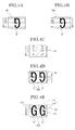
- FIG. 4A and FIG. 4B in a frame format, in the case an image of one letter "G" is formed to be inverted in up and down as well as right and left directions on separate image receiving devices 9a and 10a, two parallel letters “G” are recorded and stored in the frame memory 16 in a state inverted in up and down as well as right and left directions.
- a processing is performed in which pixel data of the letter "G” recorded and stored in the frame memory 16 and inverted in up and down as well as right and left directions is read out in a reverse sequence and displayed on a screen 17a of the monitoring device 17.
- Tested eye images G' and G" formed on both image receiving devices 9a and 10a and inverted in up and down as well as right and left directions is displayed as a tested eye composite image GG on the screen 17a of the monitoring device 7 in a state the same to when the front lens 6 is not inserted between the tested eye E and the objective lens 3.
- the tester simultaneously views the left tested eye image G' by only the left eye and the right tested eye image G" by only the right eye so that the tested eye composite image GG can be observed sterically.
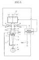
- FIG. 5 is an approximate constitutional diagram illustrating a second embodiment of a binocular stereo video microscope apparatus according to the present invention.
- 18 is a left reflective prism
- 19 is a right reflective prism.
- the left reflective prism is disposed between the imaging lens 11 and the left TV camera 9.
- the right reflective prism 19 is disposed between the imaging lens 11 and the right TV camera 10.
- the binocular stereo video microscope apparatus illustrated in FIG. 5 is a representative example in which image forming light beams guided to observatory optical systems 7, 8 receive an odd number of times of reflections to be formed on both image receiving devices 9a and 10a.
- the remaining constitutions are approximately the same to the first embodiment so that detailed descriptions of the same constituent elements are abbreviated and only differing parts are described.
- a tested eye image G' to be formed on the left image receiving device 9a disposed in the left observatory optical system 7 is actually formed on the left image receiving device 9a as an image flipped over in up and down directions.
- a tested eye image G" to be formed on the right image receiving device 10a disposed in the right observatory optical system 8 is actually formed on the right image receiving device 10a as an image flipped over in up and down directions.
- the tested eye image G" to be formed on the right image receiving device 10a disposed in the right observatory optical system 8 when the front lens 6 is not inserted between the tested eye E and the objective lens 3, is actually formed on the left image receiving device 9a as an inverted image inverted in up and down as well as right and left directions.
- the tested eye image G" to be formed on the right image receiving device 10a disposed in the right observatory optical system 8 when the front lens 6 is not inserted between the tested eye E and the objective lens 3 is actually formed on the left image receiving device 9a as an inverted image inverted in up and down as well as right and left directions.
- a tested eye image G" is formed on the left image receiving device 9a as illustrated in FIG. 7A to be flipped over in up and down directions against the tested eye image G" (refer to FIG. 4A ) formed on the left image receiving device 9a when the front lens of the first embodiment is inserted between the tested eye E and the objective lens 3.
- a tested eye image G' is formed on the right image receiving device 10a as illustrated in FIG. 7B to be flipped over in up and down directions against the tested eye image G' (refer to FIG. 4B ) formed on the right image receiving device 10a when the front lens of the first embodiment is inserted between the tested eye E and the objective lens 3.
- the calculation processing circuit 13 performs the processings described hereinbelow.
- the tested eye image G' to be formed on the left image receiving device 9a disposed in the left observatory optical system 7 is actually formed on the left image receiving device 9a as an image flipped over in up and down directions.
- the tested eye image G" to be formed on the right image receiving device 10a disposed in the right observatory optical system 8 is actually formed on the right image receiving device 10a as an image flipped over in up and down directions.
- image processings by the calculation processing part 13A is the same to image processings of FIG. 3A through 3C or FIG. 4A through 4C of the first embodiment so that descriptions of which are hereby abbreviated.
- a tested eye composite image GG flipped over in up and down directions are formed on the frame memory 16.
- the calculation processing part 13A after implementing the consecutive processings, reads out pixel data of the frame memory 16 from a lower left corner towards an upper right corner with regard to each pixel of the frame memory 16. That is, the calculation processing part 13A scans from left to right of line n and reads out pixel data of line nL. Next, the calculation processing part 13A scans from left towards right pixel memories of line n-1, line n-2, ... , line 1 towards a top so that pixel data of line n-1, line n-2, ... , line 1 is read out. In such a way, the calculation processing circuit 13A, as illustrated in FIG. 6E , forms based on pixel data dot images on a screen 17a of the monitoring device 17 in sequence from an upper left corner towards a lower right corner following a sequence of the read out pixel data.
- the tested eye image G' to be displayed in the left is displayed in the left screen part 17a' and the tested eye image G" to be displayed in the right is displayed in the right screen part 17a". Both images are together disposed in parallel as a regular image "G”.
- the tester simultaneously views the left tested eye image G' by only the left eye and the right tested eye image G" by only the right eye so that the tested eye composite image GG can be observed sterically.
- the tested eye image G" to be formed on the right image receiving device 10a disposed in the right observatory optical system 8 when the front lens 6 is not inserted between the tested eye E and the objective lens 3, is actually formed on the left image receiving device 9a as an inverted image inverted in up and down as well as right and left directions.
- the tested eye image G' to be formed on the left image receiving device 9a disposed in the left observatory optical system 7 when the front lens 6 is not inserted between the tested eye E and the objective lens 3 is actually formed on the right image receiving device 10a as an inverted image inverted in up and down as well as right and left directions.
- image processings by the calculation processing part 13A is the same to image processings of when the front lens 6 is not inserted between the tested eye E and the objective lens 3 (refer to FIG. 7A through FIG. 7C ).
- the calculation processing part 13A when the inverted image cancellation switch is manipulated to be turned on or when the inverted image cancellation switch SW2 is automatically turned on due to insertion of the front lens 6 between the tested eye E and the objective lens 3, scan each pixel memory of the frame memory 16 from an upper right corner to a lower left corner. That is, as illustrated in FIG. 7D , the calculation processing part 13A reads out from right towards left of line 1 pixel data stored in pixel memory. Next, the calculation processing part 13A reads out pixel data from right towards left of line 2. This is repeated until read out of pixel data of line n is finished.
- the calculation processing part 13A as illustrated in FIG.
- tested eye images G' and G" formed on both image receiving devices 9a and 10a to be inverted in up and down as well as right and left directions are displayed as a tested eye composite images GG of a same state to when the front lens 6 is not inserted between the tested eye E and the objective lens 3 in which an optical system illustrated in FIG. 1 is used for observation.
- a binocular stereo video microscope apparatus in which image forming relationships can return to a normal state even if an inverter device constituted from an optical device that inverts image forming relationships is not used, and stereo image can be produced for a tester.
Landscapes
- Health & Medical Sciences (AREA)
- Physics & Mathematics (AREA)
- Life Sciences & Earth Sciences (AREA)
- General Health & Medical Sciences (AREA)
- Surgery (AREA)
- Engineering & Computer Science (AREA)
- Biophysics (AREA)
- Heart & Thoracic Surgery (AREA)
- Medical Informatics (AREA)
- Molecular Biology (AREA)
- Ophthalmology & Optometry (AREA)
- Animal Behavior & Ethology (AREA)
- Biomedical Technology (AREA)
- Public Health (AREA)
- Veterinary Medicine (AREA)
- Chemical & Material Sciences (AREA)
- Analytical Chemistry (AREA)
- General Physics & Mathematics (AREA)
- Optics & Photonics (AREA)
- Microscoopes, Condenser (AREA)
Applications Claiming Priority (1)
| Application Number | Priority Date | Filing Date | Title |
|---|---|---|---|
| JP2008158781A JP2010000110A (ja) | 2008-06-18 | 2008-06-18 | 二眼式ステレオビデオ顕微鏡装置 |
Publications (1)
| Publication Number | Publication Date |
|---|---|
| EP2136232A1 true EP2136232A1 (de) | 2009-12-23 |
Family
ID=41078023
Family Applications (1)
| Application Number | Title | Priority Date | Filing Date |
|---|---|---|---|
| EP09162689A Ceased EP2136232A1 (de) | 2008-06-18 | 2009-06-15 | Video-Stereomikroskopvorrichtung mit zwei Okularen |
Country Status (2)
| Country | Link |
|---|---|
| EP (1) | EP2136232A1 (de) |
| JP (1) | JP2010000110A (de) |
Cited By (4)
| Publication number | Priority date | Publication date | Assignee | Title |
|---|---|---|---|---|
| CN102572458A (zh) * | 2010-12-17 | 2012-07-11 | 北京牡丹电子集团有限责任公司 | 立体显示装置的左右眼亮度串扰值测量方法 |
| CN103686162A (zh) * | 2013-12-27 | 2014-03-26 | 京东方科技集团股份有限公司 | 一种3d显示串扰的测试方法及装置 |
| CN111035359A (zh) * | 2019-12-28 | 2020-04-21 | 重庆贝奥新视野医疗设备有限公司 | 一种立体成像眼底照相机系统 |
| EP3324817B1 (de) | 2015-10-16 | 2020-12-30 | Alcon Inc. | Ophthalmische chirurgische bildverarbeitung |
Families Citing this family (1)
| Publication number | Priority date | Publication date | Assignee | Title |
|---|---|---|---|---|
| DE102017121085C5 (de) * | 2017-09-12 | 2025-01-23 | Carl Zeiss Meditec Ag | Augenchirurgie-Visualisierungssystem |
Citations (8)
| Publication number | Priority date | Publication date | Assignee | Title |
|---|---|---|---|---|
| US4744633A (en) * | 1986-02-18 | 1988-05-17 | Sheiman David M | Stereoscopic viewing system and glasses |
| WO1990015356A1 (en) * | 1989-06-08 | 1990-12-13 | Donald Edmund Trumbull | Stereoscopic viewing apparatus and method and related stereoscopic recording |
| US5438456A (en) * | 1991-03-14 | 1995-08-01 | Grinblat; Avi | Optical stereoscopic microscope system |
| GB2342181A (en) * | 1998-09-11 | 2000-04-05 | Keeler Ltd | Ophthalmoscope and image detction means |
| DE20021955U1 (de) * | 2000-12-23 | 2001-03-15 | Oculus Optikgeräte GmbH, 35582 Wetzlar | Mikroskop zur Weitwinkelbeobachtung, insbesondere für Augenoperationen |
| EP1293816A2 (de) * | 2001-09-17 | 2003-03-19 | Iekado Sibata | Operationsmikroskop |
| DE10336475A1 (de) * | 2003-08-08 | 2005-03-10 | Zeiss Carl | Mikroskopiesystem |
| US20070121203A1 (en) * | 2005-10-21 | 2007-05-31 | Truevision Systems, Inc. | Stereoscopic electronic microscope workstation |
Family Cites Families (4)
| Publication number | Priority date | Publication date | Assignee | Title |
|---|---|---|---|---|
| JP2001108906A (ja) * | 1999-10-01 | 2001-04-20 | Topcon Corp | 手術用顕微鏡 |
| JP2002272760A (ja) * | 2001-01-09 | 2002-09-24 | Kamon Shibata | 手術用顕微鏡システム |
| DE102004050893B4 (de) * | 2003-10-31 | 2015-05-21 | Carl Zeiss Meditec Ag | Tubus mit zwei umschaltbaren Planoptikelementen zur wahlweisen Strahlengangvertauschung und Bildumkehr für ein Mikroskop sowie Mikroskop |
| DE102005011781B4 (de) * | 2005-03-11 | 2007-06-06 | Carl Zeiss Surgical Gmbh | Ophthalmo-Operationsmikroskop mit Fokusversatz |
-
2008
- 2008-06-18 JP JP2008158781A patent/JP2010000110A/ja active Pending
-
2009
- 2009-06-15 EP EP09162689A patent/EP2136232A1/de not_active Ceased
Patent Citations (8)
| Publication number | Priority date | Publication date | Assignee | Title |
|---|---|---|---|---|
| US4744633A (en) * | 1986-02-18 | 1988-05-17 | Sheiman David M | Stereoscopic viewing system and glasses |
| WO1990015356A1 (en) * | 1989-06-08 | 1990-12-13 | Donald Edmund Trumbull | Stereoscopic viewing apparatus and method and related stereoscopic recording |
| US5438456A (en) * | 1991-03-14 | 1995-08-01 | Grinblat; Avi | Optical stereoscopic microscope system |
| GB2342181A (en) * | 1998-09-11 | 2000-04-05 | Keeler Ltd | Ophthalmoscope and image detction means |
| DE20021955U1 (de) * | 2000-12-23 | 2001-03-15 | Oculus Optikgeräte GmbH, 35582 Wetzlar | Mikroskop zur Weitwinkelbeobachtung, insbesondere für Augenoperationen |
| EP1293816A2 (de) * | 2001-09-17 | 2003-03-19 | Iekado Sibata | Operationsmikroskop |
| DE10336475A1 (de) * | 2003-08-08 | 2005-03-10 | Zeiss Carl | Mikroskopiesystem |
| US20070121203A1 (en) * | 2005-10-21 | 2007-05-31 | Truevision Systems, Inc. | Stereoscopic electronic microscope workstation |
Cited By (6)
| Publication number | Priority date | Publication date | Assignee | Title |
|---|---|---|---|---|
| CN102572458A (zh) * | 2010-12-17 | 2012-07-11 | 北京牡丹电子集团有限责任公司 | 立体显示装置的左右眼亮度串扰值测量方法 |
| CN102572458B (zh) * | 2010-12-17 | 2015-09-16 | 北京牡丹电子集团有限责任公司 | 立体显示装置的左右眼亮度串扰值测量方法 |
| CN103686162A (zh) * | 2013-12-27 | 2014-03-26 | 京东方科技集团股份有限公司 | 一种3d显示串扰的测试方法及装置 |
| US9641832B2 (en) | 2013-12-27 | 2017-05-02 | Boe Technology Group Co., Ltd. | 3D display cross interference testing method and testing device thereof |
| EP3324817B1 (de) | 2015-10-16 | 2020-12-30 | Alcon Inc. | Ophthalmische chirurgische bildverarbeitung |
| CN111035359A (zh) * | 2019-12-28 | 2020-04-21 | 重庆贝奥新视野医疗设备有限公司 | 一种立体成像眼底照相机系统 |
Also Published As
| Publication number | Publication date |
|---|---|
| JP2010000110A (ja) | 2010-01-07 |
Similar Documents
| Publication | Publication Date | Title |
|---|---|---|
| EP1779766B1 (de) | Endoskopsignalverarbeitungsvorrichtung | |
| JP5684033B2 (ja) | 撮像装置及び内視鏡装置の作動方法 | |
| CN109031642B (zh) | 一种通用的体视显微裸眼可视化的显示方法和系统装置 | |
| JP2004101871A (ja) | 顕微鏡画像撮影装置 | |
| EP2136232A1 (de) | Video-Stereomikroskopvorrichtung mit zwei Okularen | |
| JPH07104193A (ja) | ワイドテレビ統合顕微鏡システム | |
| US9408528B2 (en) | Stereoscopic endoscope system | |
| JPH04138127A (ja) | 内視鏡網目画像軽減装置 | |
| JP3070022B2 (ja) | 超広角内視鏡 | |
| JPH0735989A (ja) | 立体視内視鏡 | |
| JPH07294827A (ja) | 内視鏡 | |
| JP4274592B2 (ja) | 画像処理装置 | |
| JPH11225965A (ja) | 眼科装置 | |
| JP2000258697A (ja) | 立体内視鏡システム | |
| US20050036111A1 (en) | Ophthalmologic image taking apparatus | |
| JPS63274911A (ja) | 電子内視鏡装置 | |
| JPH01197716A (ja) | 電子内視鏡の拡大撮影機構 | |
| JPH11206714A (ja) | 立体眼底像形成方法及び立体眼底像形成システム | |
| JP2933161B2 (ja) | 内視鏡装置 | |
| JP4464103B2 (ja) | 画像表示システム | |
| JP4709784B2 (ja) | 内視鏡用信号処理装置 | |
| JP4531925B2 (ja) | 光ファイバ、光部品の観測装置 | |
| US10602113B2 (en) | Medical imaging device and medical observation system | |
| JPH05316434A (ja) | 高分解能撮像装置 | |
| JPH02272413A (ja) | 顕微鏡装置 |
Legal Events
| Date | Code | Title | Description |
|---|---|---|---|
| PUAI | Public reference made under article 153(3) epc to a published international application that has entered the european phase |
Free format text: ORIGINAL CODE: 0009012 |
|
| AK | Designated contracting states |
Kind code of ref document: A1 Designated state(s): AT BE BG CH CY CZ DE DK EE ES FI FR GB GR HR HU IE IS IT LI LT LU LV MC MK MT NL NO PL PT RO SE SI SK TR |
|
| 17P | Request for examination filed |
Effective date: 20100409 |
|
| 17Q | First examination report despatched |
Effective date: 20100511 |
|
| STAA | Information on the status of an ep patent application or granted ep patent |
Free format text: STATUS: THE APPLICATION HAS BEEN REFUSED |
|
| 18R | Application refused |
Effective date: 20121023 |