EP2136174A2 - Abgaswärmetauscher - Google Patents
Abgaswärmetauscher Download PDFInfo
- Publication number
- EP2136174A2 EP2136174A2 EP09007732A EP09007732A EP2136174A2 EP 2136174 A2 EP2136174 A2 EP 2136174A2 EP 09007732 A EP09007732 A EP 09007732A EP 09007732 A EP09007732 A EP 09007732A EP 2136174 A2 EP2136174 A2 EP 2136174A2
- Authority
- EP
- European Patent Office
- Prior art keywords
- beads
- heat exchanger
- bead
- jacket tube
- exchanger according
- Prior art date
- Legal status (The legal status is an assumption and is not a legal conclusion. Google has not performed a legal analysis and makes no representation as to the accuracy of the status listed.)
- Granted
Links
Images

Classifications
-
- F—MECHANICAL ENGINEERING; LIGHTING; HEATING; WEAPONS; BLASTING
- F28—HEAT EXCHANGE IN GENERAL
- F28D—HEAT-EXCHANGE APPARATUS, NOT PROVIDED FOR IN ANOTHER SUBCLASS, IN WHICH THE HEAT-EXCHANGE MEDIA DO NOT COME INTO DIRECT CONTACT
- F28D7/00—Heat-exchange apparatus having stationary tubular conduit assemblies for both heat-exchange media, the media being in contact with different sides of a conduit wall
- F28D7/10—Heat-exchange apparatus having stationary tubular conduit assemblies for both heat-exchange media, the media being in contact with different sides of a conduit wall the conduits being arranged one within the other, e.g. concentrically
- F28D7/106—Heat-exchange apparatus having stationary tubular conduit assemblies for both heat-exchange media, the media being in contact with different sides of a conduit wall the conduits being arranged one within the other, e.g. concentrically consisting of two coaxial conduits or modules of two coaxial conduits
-
- F—MECHANICAL ENGINEERING; LIGHTING; HEATING; WEAPONS; BLASTING
- F02—COMBUSTION ENGINES; HOT-GAS OR COMBUSTION-PRODUCT ENGINE PLANTS
- F02M—SUPPLYING COMBUSTION ENGINES IN GENERAL WITH COMBUSTIBLE MIXTURES OR CONSTITUENTS THEREOF
- F02M26/00—Engine-pertinent apparatus for adding exhaust gases to combustion-air, main fuel or fuel-air mixture, e.g. by exhaust gas recirculation [EGR] systems
- F02M26/13—Arrangement or layout of EGR passages, e.g. in relation to specific engine parts or for incorporation of accessories
- F02M26/22—Arrangement or layout of EGR passages, e.g. in relation to specific engine parts or for incorporation of accessories with coolers in the recirculation passage
- F02M26/29—Constructional details of the coolers, e.g. pipes, plates, ribs, insulation or materials
-
- F—MECHANICAL ENGINEERING; LIGHTING; HEATING; WEAPONS; BLASTING
- F28—HEAT EXCHANGE IN GENERAL
- F28D—HEAT-EXCHANGE APPARATUS, NOT PROVIDED FOR IN ANOTHER SUBCLASS, IN WHICH THE HEAT-EXCHANGE MEDIA DO NOT COME INTO DIRECT CONTACT
- F28D7/00—Heat-exchange apparatus having stationary tubular conduit assemblies for both heat-exchange media, the media being in contact with different sides of a conduit wall
- F28D7/16—Heat-exchange apparatus having stationary tubular conduit assemblies for both heat-exchange media, the media being in contact with different sides of a conduit wall the conduits being arranged in parallel spaced relation
- F28D7/1684—Heat-exchange apparatus having stationary tubular conduit assemblies for both heat-exchange media, the media being in contact with different sides of a conduit wall the conduits being arranged in parallel spaced relation the conduits having a non-circular cross-section
-
- F—MECHANICAL ENGINEERING; LIGHTING; HEATING; WEAPONS; BLASTING
- F28—HEAT EXCHANGE IN GENERAL
- F28F—DETAILS OF HEAT-EXCHANGE AND HEAT-TRANSFER APPARATUS, OF GENERAL APPLICATION
- F28F1/00—Tubular elements; Assemblies of tubular elements
- F28F1/02—Tubular elements of cross-section which is non-circular
- F28F1/04—Tubular elements of cross-section which is non-circular polygonal, e.g. rectangular
-
- F—MECHANICAL ENGINEERING; LIGHTING; HEATING; WEAPONS; BLASTING
- F28—HEAT EXCHANGE IN GENERAL
- F28F—DETAILS OF HEAT-EXCHANGE AND HEAT-TRANSFER APPARATUS, OF GENERAL APPLICATION
- F28F3/00—Plate-like or laminated elements; Assemblies of plate-like or laminated elements
- F28F3/02—Elements or assemblies thereof with means for increasing heat-transfer area, e.g. with fins, with recesses, with corrugations
- F28F3/04—Elements or assemblies thereof with means for increasing heat-transfer area, e.g. with fins, with recesses, with corrugations the means being integral with the element
- F28F3/042—Elements or assemblies thereof with means for increasing heat-transfer area, e.g. with fins, with recesses, with corrugations the means being integral with the element in the form of local deformations of the element
-
- F—MECHANICAL ENGINEERING; LIGHTING; HEATING; WEAPONS; BLASTING
- F28—HEAT EXCHANGE IN GENERAL
- F28F—DETAILS OF HEAT-EXCHANGE AND HEAT-TRANSFER APPARATUS, OF GENERAL APPLICATION
- F28F9/00—Casings; Header boxes; Auxiliary supports for elements; Auxiliary members within casings
- F28F9/001—Casings in the form of plate-like arrangements; Frames enclosing a heat exchange core
-
- B—PERFORMING OPERATIONS; TRANSPORTING
- B21—MECHANICAL METAL-WORKING WITHOUT ESSENTIALLY REMOVING MATERIAL; PUNCHING METAL
- B21D—WORKING OR PROCESSING OF SHEET METAL OR METAL TUBES, RODS OR PROFILES WITHOUT ESSENTIALLY REMOVING MATERIAL; PUNCHING METAL
- B21D17/00—Forming single grooves in sheet metal or tubular or hollow articles
- B21D17/02—Forming single grooves in sheet metal or tubular or hollow articles by pressing
-
- B—PERFORMING OPERATIONS; TRANSPORTING
- B21—MECHANICAL METAL-WORKING WITHOUT ESSENTIALLY REMOVING MATERIAL; PUNCHING METAL
- B21D—WORKING OR PROCESSING OF SHEET METAL OR METAL TUBES, RODS OR PROFILES WITHOUT ESSENTIALLY REMOVING MATERIAL; PUNCHING METAL
- B21D53/00—Making other particular articles
- B21D53/02—Making other particular articles heat exchangers or parts thereof, e.g. radiators, condensers fins, headers
- B21D53/04—Making other particular articles heat exchangers or parts thereof, e.g. radiators, condensers fins, headers of sheet metal
-
- F—MECHANICAL ENGINEERING; LIGHTING; HEATING; WEAPONS; BLASTING
- F28—HEAT EXCHANGE IN GENERAL
- F28D—HEAT-EXCHANGE APPARATUS, NOT PROVIDED FOR IN ANOTHER SUBCLASS, IN WHICH THE HEAT-EXCHANGE MEDIA DO NOT COME INTO DIRECT CONTACT
- F28D21/00—Heat-exchange apparatus not covered by any of the groups F28D1/00 - F28D20/00
- F28D21/0001—Recuperative heat exchangers
- F28D21/0003—Recuperative heat exchangers the heat being recuperated from exhaust gases
-
- F—MECHANICAL ENGINEERING; LIGHTING; HEATING; WEAPONS; BLASTING
- F28—HEAT EXCHANGE IN GENERAL
- F28F—DETAILS OF HEAT-EXCHANGE AND HEAT-TRANSFER APPARATUS, OF GENERAL APPLICATION
- F28F2225/00—Reinforcing means
- F28F2225/02—Reinforcing means for casings
Definitions
- the invention relates to an exhaust gas heat exchanger with a jacket tube made of sheet steel according to the features in the preamble of claim 1.
- Such an exhaust gas heat exchanger is used in engine construction.
- the jacket tube which is referred to in professional circles as a cooling cassette, formed from a partitioned off from a rectangular tube length portion. Due to the predetermined cross-sectional shape of the rectangular tube, the practice is therefore bound to it and consequently limited in terms of the available installation space. Furthermore, due to the tubular shape, the range of variation for the definition of connections and / or attachments is naturally limited.
- the invention has for its object to provide an exhaust gas heat exchanger with a jacket tube, both in terms of its design as Also with regard to connections and / or attachments can be flexibly adapted to the available installation space.
- the jacket tube of the exhaust gas heat exchanger is formed from a board, which is punched according to the desired specifications, then formed into a polygonal tube and then longitudinally welded.
- a jacket tube it is now readily possible to produce a deviating from the rectangular cross-section geometry.
- a trapezoidal or approximately trapezoidal cross section is conceivable.
- a longitudinally stepped casing tube can be produced, whereby an even better adaptation to the respective available installation space is possible.
- the invention provides the prerequisites that measures can already be taken on the board to be punched to provide connections or attachments without significant design effort on the finished jacket pipe.
- the jacket tube forms the housing of the exhaust gas heat exchanger.
- the heat exchange itself takes place in the space enclosed by the jacket tube interior, so that the jacket tube itself does not participate in the heat exchange.
- casing pipe and the name cooling cassette is common because exhaust gases are cooled within the designed in cassette exhaust heat exchanger.
- the features of claim 2 provide that at least one side wall of the jacket tube is provided with beads.
- the introduction of the beads is done before forming the board to a polygonal pipe.
- at least two opposing side walls of the jacket tube provided with preferably embossed from the inside outward beads (claim 5). Due to the jacket tube reinforcing beads can be met with such a jacket pipe requirements of practice, after which the jacket tube must withstand a required bursting pressure of eg 5 bar.
- the production of the beads prepares the punching of the board no significant manufacturing problems.
- a particularly advantageous embodiment of the arrangement of beads is achieved within the scope of the features of claim 2.
- S-bead S-shaped curve
- the S-bead has concave end portions toward the central longitudinal line of the sidewall.
- open C-shaped beads C-beads
- Between the end sections of the S-bead and the C-beads are located in the region of the center longitudinal line lying round beads (round beads) and in the area of the central transverse line of the side wall next to a diagonal leg of the S-bead arranged triangular beads (triangular beads). All beads are embossed from the inside out.
- Such a bead image thus extends over the entire surface of a side wall and increases the rigidity of the jacket tube to a substantial extent.
- all beads are embossed from the inside to the outside.
- the features of claim 8 provide that the jacket tube is made of stainless steel sheet, aluminum sheet or plastic.
- openings are provided in a preferably bead-free side wall of the jacket tube. These openings are preferably used to connect pipes for feeding and discharging, in particular a coolant.
- FIGS. 1 to 3 denotes a jacket tube of an otherwise not illustrated exhaust gas heat exchanger.
- the jacket tube 1 has a rectangular cross-section.
- Two mutually opposite side walls 2 of the jacket tube 1 have in an identical configuration a below explained in more detail Sickenchan 3 for stiffening the jacket tube 1, while the other two side walls 4 designed without a sicken are.
- the side walls 2, 4 are connected to each other via rounded longitudinal edges 18.
- S-bead 5 extends over each side wall 2 in an oblique orientation an S-shaped bead 5 (hereinafter referred to as S-bead 5).
- the S-bead 5 has a central diagonal leg 6 and in the direction of the central longitudinal line MLL of the side wall 2 opposite concave curved end portions 7. Due to the concave design of the end portions 7 short end legs 8 are formed, which are directed to the central longitudinal line MLL out.
- the central transverse line MQL of the side wall 2 of the diagonal leg 6 of the S-bead 5 is provided with a circular extension 9. The lying next to the extension 9 longitudinal portions 10 of the diagonal leg 6 widen in the direction of the concave end portions. 7
- C-shaped beads 11 are arranged toward the end sections 7 (referred to below as C-beads 11 for short).
- One leg 12 of the C-beads 11 extends parallel to the diagonal leg 6 of the S-bead 5, while the other leg 13 is directed to the short leg 8 of the end portions 7 of the S-bead 5 out.
- the webs 14 of the C-beads 11 between the end legs 12, 13 are formed widened in the middle length ranges.
- triangular shaped beads 16 are provided (referred to below as triangle triangles 16), each of which faces the extensions 9 with one corner 17 each.
- the corners 17 remote from the sides 27 extend parallel to the Longitudinal edge 4.
- the triangular pitches 16 may be formed on the same side or on opposite sides.
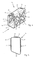
- the cross section is designed approximately trapezoidal.
- Two side walls 20, 21 extend parallel to one another, while a third side wall 22 is arranged at right angles to the two side walls 20, 21 lying parallel to one another.
- the fourth side wall 23 extends obliquely to the side walls 20, 21st
- the mutually parallel side walls 20, 21 are provided with bead images 3, which like the bead images 3 in the side walls 2 of the casing tube 1 according to the FIGS. 1 to 3 are formed. A repeated explanation is therefore unnecessary.
- openings 24, 25 are provided in one end region.
- a rectangular opening 24 is provided, while in the other end region is a round opening 25, which is provided with a passage 26 to the outside.
Landscapes
- Engineering & Computer Science (AREA)
- Physics & Mathematics (AREA)
- Mechanical Engineering (AREA)
- General Engineering & Computer Science (AREA)
- Thermal Sciences (AREA)
- Geometry (AREA)
- Chemical & Material Sciences (AREA)
- Combustion & Propulsion (AREA)
- Heat-Exchange Devices With Radiators And Conduit Assemblies (AREA)
- Exhaust Silencers (AREA)
Abstract
Description
- Die Erfindung betrifft einen Abgaswärmetauscher mit einem Mantelrohr aus Stahlblech gemäß den Merkmalen im Oberbegriff des Anspruchs 1.
- Ein derartiger Abgaswärmetauscher wird im Motorenbau eingesetzt. Bei einem bekannten Abgaswärmetauscher wird das Mantelrohr, das in Fachkreisen auch als Kühlkassette bezeichnet wird, aus einem von einem Rechteckrohr abgeteilten Längenabschnitt gebildet. Aufgrund der vorgegebenen Querschnittsform des Rechteckrohrs ist die Praxis mithin hieran gebunden und folglich hinsichtlich des zur Verfügung stehenden Einbauraums eingeschränkt. Ferner ist auf Grund der Rohrform die Variationsbreite für die Festlegung von Anschlüssen und/ oder Anbauteilen naturgemäß eingeschränkt.
- Der Erfindung liegt die Aufgabe zugrunde, einen Abgaswärmetauscher mit einem Mantelrohr zu schaffen, das sowohl hinsichtlich seiner Ausgestaltung als auch im Hinblick auf Anschlüsse und/ oder Anbauteile flexibler an den zur Verfügung stehenden Einbauraum angepasst werden kann.
- Die Lösung dieser Aufgabe wird nach der Erfindung in den Merkmalen des Anspruchs 1 gesehen.
- Das Mantelrohr des Abgaswärmetauschers wird aus einer Platine gebildet, die entsprechend den gewünschten Vorgaben gestanzt, anschließend zu einem mehrkantigen Rohr umgeformt und dann längsnahtgeschweißt wird. Bei einem derartigen Mantelrohr ist es nunmehr ohne weiteres möglich, eine vom rechteckigen Querschnitt abweichende Geometrie zu fertigen. So ist zum Beispiel ein trapezförmiger beziehungsweise annähernd trapezförmiger Querschnitt denkbar. Darüber hinaus kann ein in Längsrichtung gestuftes Mantelrohr hergestellt werden, wodurch eine noch bessere Anpassung an den jeweils zur Verfügung stehenden Einbauraum möglich ist. Ferner schafft die Erfindung die Vorausetzungen dafür, dass bereits an der zu stanzenden Platine Maßnahmen getroffen werden können, um ohne wesentlichen konstruktiven Aufwand an dem fertig gestellten Mantelrohr Anschlüsse oder Anbauteile vorzusehen.
- Das Mantelrohr bildet das Gehäuse des Abgaswärmetauschers. Der Wärmetausch selbst findet in dem von dem Mantelrohr umschlossenen Innenraum statt, so dass das Mantelrohr selbst am Wärmetausch nicht teilnimmt. Anstelle des Begriffs Mantelrohr ist auch die Bezeichnung Kühlkassette üblich, da Abgase innerhalb des in Kassettenbauweise ausgestalteten Abgaswärmetauschers gekühlt werden.
- In vorteilhafter Ausgestaltung des erfindungsgemäßen Grundgedankens sehen die Merkmale des Anspruchs 2 vor, dass wenigstens eine Seitenwand des Mantelrohrs mit Sicken versehen ist. Das Einbringen der Sicken erfolgt vor dem Umformen der Platine zu einem mehrkantigen Rohr. Insbesondere sind mindestens zwei einander gegenüberliegende Seitenwände des Mantelrohrs mit vorzugsweise von innen nach außen geprägten Sicken versehen (Patentanspruch 5). Aufgrund der das Mantelrohr verstärkenden Sicken können mit einem solchen Mantelrohr die Anforderungen der Praxis eingehalten werden, wonach das Mantelrohr einem geforderten Berstdruck von z.B. 5 bar standhalten muss. Die Herstellung der Sicken bereitet beim Stanzen der Platine keine wesentlichen fertigungstechnischen Probleme.
- Eine besonders vorteilhafte Ausführungsform der Anordnung von Sicken wird im Umfang der Merkmale des Anspruchs 2 erzielt. Danach sind mindestens zwei einander gegenüberliegende Seitenwände des Mantelrohrs mit jeweils einer sich schräg über eine Seitenwand erstreckenden Sicke mit S-förmigen Verlauf (S-Sicke) versehen. Die S-Sicke weist zur Mittellängslinie der Seitenwand hin konkave Endabschnitte auf. Ferner sind zu diesen Endabschnitten hin offene C-förmigen Sicken (C-Sicken) vorgesehen. Zwischen den Endabschnitten der S-Sicke und den C-Sicken befinden sich im Bereich der in Mittellängslinie liegenden runde Sicken (Rundsicken) und in im Bereich der Mittelquerlinie der Seitenwand neben einem Diagonalschenkel der S-Sicke angeordneten dreieckförmige Sicken (Dreiecksicken). Alle Sicken sind von innen nach außen geprägt. Ein derartiges Sickenbild erstreckt sich mithin über die komplette Fläche einer Seitenwand und erhöht die Steifigkeit des Mantelrohrs in einem wesentlichen Umfang. Vorzugsweise sind alle Sicken von innen nach außen geprägt.
- Die Bereiche neben den Diagonalschenkein der S-Sicken werden entsprechend Anspruch 6 dadurch flächenmäßig besser ausgenutzt, dass die Dreiecksicken mit jeweils einer Ecke einander zugewandt sind.
- Eine zusätzliche Versteifung des Mantelrohrs wird mit den Merkmalen des Anspruchs 7 erreicht. Danach sind die Diagonalschenkel der S-Sicken im Bereich der Mittelquerlinie der Seitenwände jeweils mit einer insbesondere kreisförmigen Erweiterung versehen. Diese kreisförmigen Erweiterungen können bei Bedarf zur Anbringung eines Logos genutzt werden.
- Um die Dicke der Seitenwände des Mantelrohrs so gering wie möglich zu halten bei gleichzeitiger Sicherheit gegen einen hohen Innendruck sehen die Merkmale des Anspruchs 8 vor, dass das Mantelrohr aus Edelstahlblech, Aluminiumblech oder auch aus Kunststoff gebildet ist.
- Schließlich ist es gemäß den Merkmalen des Anspruchs 9 noch von Vorteil, dass in einer vorzugsweise sickenfreien Seitenwand des Mantelrohrs Öffnungen vorgesehen sind. Diese Öffnungen dienen bevorzugt dem Anschluss von Rohren zur Zu- und Abführung insbesondere eines Kühlmittels.
- Die Erfindung ist nachfolgend anhand von in den Zeichnungen dargestellten Ausführungsbeispielen näher erläutert. Es zeigen:
- Figur 1
- in der Perspektive ein Mantelrohr eines Abgaswärmetauschers;
- Figur 2
- eine Seitenansicht des Mantelrohrs der
Figur 1 ; - Figur 3
- eine Draufsicht auf das Mantelrohr der
Figur 2 in Richtung des Pfeils III gesehen; - Figur 4
- in der Perspektive eine weitere Ausführungsform eines Mantelrohrs für einen Abgaswärmetauscher und
- Figur 5
- eine Stirnansicht des Mantelrohrs der
Figur 4 in Richtung des Pfeils V gesehen. - Mit 1 ist in den
Figuren 1 bis 3 ein Mantelrohr eines ansonsten nicht näher veranschaulichten Abgaswärmetauschers bezeichnet. Das Mantelrohr 1 weist einen rechteckförmigen Querschnitt auf. Zwei einander gegenüberliegende Seitenwände 2 des Mantelrohrs 1 besitzen in identischer Konfiguration ein nachfolgend noch näher erläutertes Sickenbild 3 zur Versteifung des Mantelrohrs 1, während die beiden anderen Seitenwände 4 sickenlos gestaltet sind. Die Seitenwände 2, 4 sind über gerundete Längskanten 18 miteinander verbunden. - Wie insbesondere die
Figur 2 erkennen lässt, erstreckt sich über jede Seitenwand 2 in schräger Ausrichtung eine S-förmig ausgebildete Sicke 5 (nachfolgend kurz S-Sicke 5 genannt). Die S-Sicke 5 besitzt einen mittleren Diagonalschenkel 6 sowie in Richtung zur Mittellängslinie MLL der Seitenwand 2 gegengleich konkav gekrümmte Endabschnitte 7. Aufgrund der konkaven Gestaltung der Endabschnitte 7 werden kurze Endschenkel 8 gebildet, die zur Mittellängslinie MLL hin gerichtet sind. In der Mittelquerlinie MQL der Seitenwand 2 ist der Diagonalschenkel 6 der S-Sicke 5 mit einer kreisförmigen Erweiterung 9 versehen. Die neben der Erweiterung 9 liegenden Längenabschnitte 10 des Diagonalschenkels 6 verbreitern sich in Richtung zu den konkav verlaufenden Endabschnitten 7. - Neben den konkav gekrümmten Endabschnitten 7 der S-Sicke 5 sind zu den Endabschnitten 7 hin offene, C-förmig ausgebildete Sicken 11 angeordnet (nachfolgend kurz C-Sicken 11 genannt). Ein Schenkel 12 der C-Sicken 11 verläuft parallel zu dem Diagonalschenkel 6 der S-Sicke 5, während der jeweils andere Schenkel 13 zu dem kurzen Schenkel 8 der Endabschnitte 7 der S-Sicke 5 hin gerichtet ist. Die Stege 14 der C-Sicken 11 zwischen den endseitigen Schenkeln 12, 13 sind in den mittleren Längenbereichen verbreitert ausgebildet.
- Zwischen den Endabschnitten 7 der S-Sicke 5 und den C-Sicken 11 liegen in der Mittellängslinie MLL der Seitenwand 2 kreisrund ausgebildete Sicken 15 (nachfolgend kurz Rundsicken 15 genannt).
- Ferner sind im Bereich der Mittelquerlinie MQL der Seitenwände 2 dreieckig gestaltete Sicken 16 vorgesehen (nachfolgend kurz Dreiecksicken 16 genannt), die mit jeweils einer Ecke 17 den Erweiterungen 9 zugewandt sind. Die den Ecken 17 abgewandten Seiten 27 erstrecken sich parallel zu den Längskante 4. Die Dreiecksicken 16 können gleichseitig oder ungleichseitig ausgebildet sein.
- Es ist insbesondere aus der
Figur 3 zu erkennen, dass alle Sicken 5, 11, 15 und 16 von innen nach außen geprägt sind. Hierbei weisen die S-Sicken 5 und die C-Sicken 11 halbrunde Querschnitte auf, während die Rundsicken 15 und die Dreiecksicken 16 gerundete Übergänge 19 zu den Seitenwänden 2 besitzen. - Bei der Ausführungsform eines Mantelrohrs 1a gemäß den
Figuren 4 und 5 ist der Querschnitt annähernd trapezförmig gestaltet. Zwei Seitenwände 20, 21 erstrecken sich parallel zueinander, während eine dritte Seitenwand 22 im rechten Winkel zu den beiden parallel zueinander liegenden Seitenwänden 20, 21 angeordnet ist. Die vierte Seitenwand 23 verläuft schräg zu den Seitenwänden 20, 21. - Die parallel zueinander angeordneten Seitenwände 20, 21 sind mit Sickenbildern 3 versehen, die wie die Sickenbilder 3 in den Seitenwänden 2 des Mantelrohrs 1 gemäß den
Figuren 1 bis 3 ausgebildet sind. Eine nochmalige Erläuterung ist daher entbehrlich. - Außerdem ist aus den
Figuren 4 und 5 noch zu erkennen, dass in den Endbereichen der sich zu den beiden parallel zu einander verlaufenden Seitenwänden 20, 21 rechtwinklig erstreckenden Seitenwand 22 Öffnungen 24, 25 vorgesehen sind. In einem Endbereich ist eine Rechtecköffnung 24 vorgesehen, während sich in dem anderen Endbereich eine runde Öffnung 25 befindet, die nach außen hin mit einem Durchzug 26 versehen ist. - Auch bei der Ausführungsform eines Mantelrohrs 1 gemäß den
Figuren 1 bis 3 können zum Beispiel in einer Seitenwand 4 Öffnungen 24, 25 gemäß denFiguren 4 und 5 vorgesehen sein. -
- 1 -
- Mantelrohr
1a - Mantelrohr - 2 -
- Seitenwände v. 1
- 3 -
- Sickenbild an 2, 20, 21
- 4 -
- Seitenwände v. 1
- 5 -
- S-Sicke v. 3
- 6 -
- Diagonalschenkel v. 5
- 7 -
- Endabschnitte v. 5
- 8-
- Endschenkel v. 7
- 9 -
- Erweiterung v. 6
- 10 -
- Längenabschnitte v. 6
- 11 -
- C-Sicken v. 3
- 12-
- Schenkel v. 11
- 13 -
- Schenkel v. 11
- 14 -
- Steg v. 11
- 15 -
- Rundsicken v. 3
- 16 -
- Dreiecksicken v. 3
- 17 -
- Ecken v. 16
- 18 -
- Längskanten v. 1, 1a
- 19 -
- Übergänge v. 15, 16 auf 2
- 20 -
- Seitenwand v. 1a
- 21 -
- Seitenwand v. 1a
- 22 -
- Seitenwand v. 1a
- 23 -
- Seitenwand v. 1a
- 24 -
- Öffnung in 22
- 25 -
- Öffnung in 22
- 26 -
- Durchzug an 25
- 27 -
- Längsseiten v. 16
- MLL -
- Mittellängslinie v. 2
- MQL -
- Mittelquerlinie v. 2
Claims (9)
- Abgaswärmetauscher mit einem rohrförmigen Mantelrohr (1, 1a) aus Stahlblech, dadurch gekennzeichnet, dass das Mantelrohr (1, 1a) aus einer gestanzten, zu einem mehrkantigen Rohr umgeformten und längsnahtgeschweißten Platine gebildet ist.
- Abgaswärmetauscher nach Anspruch 1, dadurch gekennzeichnet, dass wenigstens eine Seitenwand (2, 20, 21) des Mantelrohrs (1, 1a) mit Sicken (5, 11, 15, 16) versehen ist.
- Abgaswärmetauscher nach einem der Ansprüche 1 oder 2, dadurch gekennzeichnet, dass mindestens zwei einander gegenüberliegende Seitenwände (2, 20, 21) des Mantelrohrs (1, 1a) mit Sicken (5, 11, 15, 16) versehen sind.
- Abgaswärmetauscher nach einem der Ansprüche 1 bis 3, dadurch gekennzeichnet, dass mindestens zwei einander gegenüberliegende Seitenwände (2, 20, 21) des Mantelrohrs (1, 1a) mit jeweils einer sich schräg über eine Seitenwand (2, 20, 21) erstreckenden Sicke mit S-förmigen Verlauf (S-Sicke) (5) versehen sind, wobei die S-Sicke (5) eine Mittellängslinie (MLL) der Seitenwand (2, 20, 21) schneidet, wobei neben zur Mittellängslinie (MLL) der Seitenwand (2, 20, 21) hin konkaven Endabschnitten (7) der S-Sicke (5) zu den Endabschnitten (7) hin offene C-Sicken (11) angeordnet sind, wobei zwischen den Endabschnitten (7) der S-Sicke (5) und den C-Sicken (11) in der Mittellängslinie (MLL) liegende Rundsicken (15) und in der Mittelquerlinie (MQL) der Seitenwand (2, 20, 21) neben einem Diagonalschenkel (6) der S-Sicke (5) angeordnete Dreiecksicken (16) vorgesehen sind.
- Abgaswärmetauscher nach einem der Ansprüche 1 bis 4, dadurch gekennzeichnet, dass alle Sicken (5, 11, 15, 16) von innen nach außen geprägt sind.
- Abgaswärmetauscher nach Anspruch 4 oder 5, dadurch gekennzeichnet, dass die Dreiecksicken (16) mit jeweils einer Ecke (17) einander zugewandt sind.
- Abgaswärmetauscher nach Anspruch 4 oder 5, dadurch gekennzeichnet, dass die Diagonalschenkel (6) der S-Sicken (5) im Bereich der Mittelquerlinie (MQL) der Seitenwände (2, 20, 21) jeweils mit einer kreisförmigen Erweiterung (9) versehen sind.
- Abgaswärmetauscher nach einem der Ansprüche 1 bis 7, dadurch gekennzeichnet, dass das Mantelrohr (1, 1a) aus Edelstahlblech, Aluminiumblech oder Kunststoff gebildet ist.
- Abgaswärmetauscher nach einem der Ansprüche 1 bis 8, dadurch gekennzeichnet, dass in einer Seitenwand (4, 22) des Mantelrohrs (1, 1a) Öffnungen (24, 25) vorgesehen sind.
Priority Applications (1)
| Application Number | Priority Date | Filing Date | Title |
|---|---|---|---|
| EP17186705.4A EP3270083B1 (de) | 2008-06-16 | 2009-06-12 | Abgaswärmetauscher |
Applications Claiming Priority (1)
| Application Number | Priority Date | Filing Date | Title |
|---|---|---|---|
| DE102008028244A DE102008028244B3 (de) | 2008-06-16 | 2008-06-16 | Abgaswärmetauscher |
Related Child Applications (2)
| Application Number | Title | Priority Date | Filing Date |
|---|---|---|---|
| EP17186705.4A Division EP3270083B1 (de) | 2008-06-16 | 2009-06-12 | Abgaswärmetauscher |
| EP17186705.4A Division-Into EP3270083B1 (de) | 2008-06-16 | 2009-06-12 | Abgaswärmetauscher |
Publications (3)
| Publication Number | Publication Date |
|---|---|
| EP2136174A2 true EP2136174A2 (de) | 2009-12-23 |
| EP2136174A3 EP2136174A3 (de) | 2012-12-05 |
| EP2136174B1 EP2136174B1 (de) | 2018-03-21 |
Family
ID=41077605
Family Applications (2)
| Application Number | Title | Priority Date | Filing Date |
|---|---|---|---|
| EP17186705.4A Active EP3270083B1 (de) | 2008-06-16 | 2009-06-12 | Abgaswärmetauscher |
| EP09007732.2A Active EP2136174B1 (de) | 2008-06-16 | 2009-06-12 | Abgaswärmetauscher |
Family Applications Before (1)
| Application Number | Title | Priority Date | Filing Date |
|---|---|---|---|
| EP17186705.4A Active EP3270083B1 (de) | 2008-06-16 | 2009-06-12 | Abgaswärmetauscher |
Country Status (4)
| Country | Link |
|---|---|
| EP (2) | EP3270083B1 (de) |
| DE (1) | DE102008028244B3 (de) |
| ES (1) | ES2665922T3 (de) |
| PT (1) | PT3270083T (de) |
Families Citing this family (2)
| Publication number | Priority date | Publication date | Assignee | Title |
|---|---|---|---|---|
| DE102010027338B4 (de) * | 2010-07-15 | 2012-04-05 | Benteler Automobiltechnik Gmbh | Wärmeaustauscher in einem Kraftfahrzeug |
| EP3751127B1 (de) * | 2019-06-11 | 2022-01-12 | Valeo Systemes Thermiques-THS | Abgasrückführungskühler |
Family Cites Families (15)
| Publication number | Priority date | Publication date | Assignee | Title |
|---|---|---|---|---|
| US1487118A (en) * | 1921-01-28 | 1924-03-18 | Solar Sturges Mfg Co | Container or can |
| GB1297941A (de) * | 1969-02-28 | 1972-11-29 | ||
| SE440275B (sv) * | 1979-03-21 | 1985-07-22 | Svante Thunberg | Vermevexlare till anleggningar for ventilering av lokaler |
| DE2915000A1 (de) * | 1979-04-12 | 1980-10-30 | Thyssen Industrie | Blechelement mit sickenfoermigen versteifungen |
| US4538439A (en) * | 1982-05-10 | 1985-09-03 | Cantec, Incorporated | Cans formed of thin-walled material and apparatus for forming precise fine beads therein |
| KR950704665A (ko) * | 1993-09-16 | 1995-11-20 | 이시마루 쓰네오 | 알루미늄제 열교환기(aluminum heat exchanger) |
| JPH10160364A (ja) * | 1996-11-28 | 1998-06-19 | Zexel Corp | 積層型熱交換器の製造方法 |
| ES1039979Y (es) * | 1998-04-16 | 1999-12-16 | Envases Ballujera S A | Envase metalico. |
| US7661415B2 (en) * | 2004-09-28 | 2010-02-16 | T.Rad Co., Ltd. | EGR cooler |
| JP4527557B2 (ja) * | 2005-01-26 | 2010-08-18 | 株式会社ティラド | 熱交換器 |
| US7195060B2 (en) * | 2005-04-01 | 2007-03-27 | Dana Canada Corporation | Stacked-tube heat exchanger |
| US7594326B2 (en) * | 2005-09-13 | 2009-09-29 | Catacel Corp. | Method for making a low-cost high-temperature heat exchanger |
| DE102006047234A1 (de) * | 2005-10-14 | 2007-04-19 | Behr Gmbh & Co. Kg | Wärmeübertrager |
| DE102005055482A1 (de) * | 2005-11-18 | 2007-05-24 | Behr Gmbh & Co. Kg | Wärmetauscher für einen Verbrennungsmotor |
| US20080236792A1 (en) * | 2007-03-28 | 2008-10-02 | Modine Manufacturing Company | Heat exchanger and method |
-
2008
- 2008-06-16 DE DE102008028244A patent/DE102008028244B3/de not_active Expired - Fee Related
-
2009
- 2009-06-12 ES ES09007732.2T patent/ES2665922T3/es active Active
- 2009-06-12 EP EP17186705.4A patent/EP3270083B1/de active Active
- 2009-06-12 EP EP09007732.2A patent/EP2136174B1/de active Active
- 2009-06-12 PT PT171867054T patent/PT3270083T/pt unknown
Also Published As
| Publication number | Publication date |
|---|---|
| ES2665922T3 (es) | 2018-04-30 |
| EP2136174A3 (de) | 2012-12-05 |
| PT3270083T (pt) | 2023-12-20 |
| DE102008028244B3 (de) | 2009-11-05 |
| EP3270083A1 (de) | 2018-01-17 |
| EP2136174B1 (de) | 2018-03-21 |
| EP3270083B1 (de) | 2023-10-25 |
Similar Documents
| Publication | Publication Date | Title |
|---|---|---|
| EP3012570B1 (de) | Wärmetauscher | |
| DE102007040793A1 (de) | Wärmetauscher | |
| EP2413080A2 (de) | Kühlvorrichtung für eine Verbrennungskraftmaschine | |
| DE102007028792A1 (de) | Wärmeaustauscher | |
| DE102007049665A1 (de) | Wärmeaustauscher | |
| DE202010018520U1 (de) | Wärmetauscher | |
| EP1769210B1 (de) | Wärmetauscher, insbesondere ladeluftkühler | |
| EP1204816A1 (de) | Mischelement für ein in einem rohr geführtes fluid | |
| WO2014001498A1 (de) | Flachrohr und wärmeübertrager mit einem solchen flachrohr | |
| EP2498040B1 (de) | Wärmetauscher und Verfahren zur Herstellung eines Wärmetauschers | |
| WO2006082084A1 (de) | Wärmetauscher | |
| DE3834822A1 (de) | Waermetauscher | |
| EP1376043A2 (de) | Wärmetauscher mit einem Diffusor | |
| DE102007039292A1 (de) | Mehrkammer-Flachrohr, Wärmetauscher und Verwendung eines Wärmetauschers | |
| EP2136174B1 (de) | Abgaswärmetauscher | |
| EP3087337B1 (de) | Wärmetauscher mit umlaufender dichtung | |
| EP3042140A1 (de) | Rohrboden | |
| DE102007047875A1 (de) | Profil | |
| DE9318525U1 (de) | Wasser/Luft-Wärmetauscher aus Aluminium für Kraftfahrzeuge | |
| DE602005000958T2 (de) | Hohlkörper für Schalldämpfer | |
| DE19704690A1 (de) | Wabenkörper mit abgeflachtem Querschnittsbereich | |
| DE102005043093A1 (de) | Wärmetauscherrohr | |
| DE102008051894A1 (de) | Belastungsangepasstes Strukturteil aus Metall für einen Wärmetauscher, Verfahren zur Herstellung eines belastungsangepassten Strukturteils, Wärmetauscher | |
| DE102005049673B4 (de) | Aus zwei wenigstens bereichsweise rohrförmigen Gehäuseteilen bestehendes Gehäuse | |
| DE102006061049A1 (de) | Wärmeaustauscher |
Legal Events
| Date | Code | Title | Description |
|---|---|---|---|
| PUAI | Public reference made under article 153(3) epc to a published international application that has entered the european phase |
Free format text: ORIGINAL CODE: 0009012 |
|
| AK | Designated contracting states |
Kind code of ref document: A2 Designated state(s): AT BE BG CH CY CZ DE DK EE ES FI FR GB GR HR HU IE IS IT LI LT LU LV MC MK MT NL NO PL PT RO SE SI SK TR |
|
| RAP1 | Party data changed (applicant data changed or rights of an application transferred) |
Owner name: BENTELER AUTOMOBILTECHNIK GMBH |
|
| PUAL | Search report despatched |
Free format text: ORIGINAL CODE: 0009013 |
|
| AK | Designated contracting states |
Kind code of ref document: A3 Designated state(s): AT BE BG CH CY CZ DE DK EE ES FI FR GB GR HR HU IE IS IT LI LT LU LV MC MK MT NL NO PL PT RO SE SI SK TR |
|
| AX | Request for extension of the european patent |
Extension state: AL BA RS |
|
| RIC1 | Information provided on ipc code assigned before grant |
Ipc: F28D 1/03 20060101ALI20121026BHEP Ipc: F28F 1/04 20060101ALI20121026BHEP Ipc: F01N 3/02 20060101ALI20121026BHEP Ipc: F28D 7/10 20060101AFI20121026BHEP Ipc: F02M 25/07 20060101ALI20121026BHEP Ipc: F28F 3/04 20060101ALI20121026BHEP |
|
| 17P | Request for examination filed |
Effective date: 20130605 |
|
| GRAP | Despatch of communication of intention to grant a patent |
Free format text: ORIGINAL CODE: EPIDOSNIGR1 |
|
| STAA | Information on the status of an ep patent application or granted ep patent |
Free format text: STATUS: GRANT OF PATENT IS INTENDED |
|
| RIC1 | Information provided on ipc code assigned before grant |
Ipc: F28F 9/00 20060101ALI20171117BHEP Ipc: F28D 7/10 20060101AFI20171117BHEP Ipc: F02M 26/29 20160101ALI20171117BHEP Ipc: F28F 3/04 20060101ALI20171117BHEP Ipc: F28F 1/04 20060101ALI20171117BHEP Ipc: F28D 7/16 20060101ALI20171117BHEP |
|
| INTG | Intention to grant announced |
Effective date: 20171212 |
|
| RAP1 | Party data changed (applicant data changed or rights of an application transferred) |
Owner name: BENTELER AUTOMOBILTECHNIK GMBH |
|
| GRAS | Grant fee paid |
Free format text: ORIGINAL CODE: EPIDOSNIGR3 |
|
| GRAA | (expected) grant |
Free format text: ORIGINAL CODE: 0009210 |
|
| STAA | Information on the status of an ep patent application or granted ep patent |
Free format text: STATUS: THE PATENT HAS BEEN GRANTED |
|
| AK | Designated contracting states |
Kind code of ref document: B1 Designated state(s): AT BE BG CH CY CZ DE DK EE ES FI FR GB GR HR HU IE IS IT LI LT LU LV MC MK MT NL NO PL PT RO SE SI SK TR |
|
| REG | Reference to a national code |
Ref country code: GB Ref legal event code: FG4D Free format text: NOT ENGLISH |
|
| REG | Reference to a national code |
Ref country code: CH Ref legal event code: EP |
|
| REG | Reference to a national code |
Ref country code: AT Ref legal event code: REF Ref document number: 981578 Country of ref document: AT Kind code of ref document: T Effective date: 20180415 |
|
| REG | Reference to a national code |
Ref country code: IE Ref legal event code: FG4D Free format text: LANGUAGE OF EP DOCUMENT: GERMAN |
|
| REG | Reference to a national code |
Ref country code: DE Ref legal event code: R096 Ref document number: 502009014830 Country of ref document: DE |
|
| REG | Reference to a national code |
Ref country code: ES Ref legal event code: FG2A Ref document number: 2665922 Country of ref document: ES Kind code of ref document: T3 Effective date: 20180430 |
|
| REG | Reference to a national code |
Ref country code: FR Ref legal event code: PLFP Year of fee payment: 10 |
|
| REG | Reference to a national code |
Ref country code: NL Ref legal event code: MP Effective date: 20180321 |
|
| PG25 | Lapsed in a contracting state [announced via postgrant information from national office to epo] |
Ref country code: CY Free format text: LAPSE BECAUSE OF FAILURE TO SUBMIT A TRANSLATION OF THE DESCRIPTION OR TO PAY THE FEE WITHIN THE PRESCRIBED TIME-LIMIT Effective date: 20180321 Ref country code: LT Free format text: LAPSE BECAUSE OF FAILURE TO SUBMIT A TRANSLATION OF THE DESCRIPTION OR TO PAY THE FEE WITHIN THE PRESCRIBED TIME-LIMIT Effective date: 20180321 Ref country code: HR Free format text: LAPSE BECAUSE OF FAILURE TO SUBMIT A TRANSLATION OF THE DESCRIPTION OR TO PAY THE FEE WITHIN THE PRESCRIBED TIME-LIMIT Effective date: 20180321 Ref country code: FI Free format text: LAPSE BECAUSE OF FAILURE TO SUBMIT A TRANSLATION OF THE DESCRIPTION OR TO PAY THE FEE WITHIN THE PRESCRIBED TIME-LIMIT Effective date: 20180321 Ref country code: NO Free format text: LAPSE BECAUSE OF FAILURE TO SUBMIT A TRANSLATION OF THE DESCRIPTION OR TO PAY THE FEE WITHIN THE PRESCRIBED TIME-LIMIT Effective date: 20180621 |
|
| REG | Reference to a national code |
Ref country code: LT Ref legal event code: MG4D |
|
| PG25 | Lapsed in a contracting state [announced via postgrant information from national office to epo] |
Ref country code: GR Free format text: LAPSE BECAUSE OF FAILURE TO SUBMIT A TRANSLATION OF THE DESCRIPTION OR TO PAY THE FEE WITHIN THE PRESCRIBED TIME-LIMIT Effective date: 20180622 Ref country code: BG Free format text: LAPSE BECAUSE OF FAILURE TO SUBMIT A TRANSLATION OF THE DESCRIPTION OR TO PAY THE FEE WITHIN THE PRESCRIBED TIME-LIMIT Effective date: 20180621 Ref country code: LV Free format text: LAPSE BECAUSE OF FAILURE TO SUBMIT A TRANSLATION OF THE DESCRIPTION OR TO PAY THE FEE WITHIN THE PRESCRIBED TIME-LIMIT Effective date: 20180321 Ref country code: SE Free format text: LAPSE BECAUSE OF FAILURE TO SUBMIT A TRANSLATION OF THE DESCRIPTION OR TO PAY THE FEE WITHIN THE PRESCRIBED TIME-LIMIT Effective date: 20180321 |
|
| PG25 | Lapsed in a contracting state [announced via postgrant information from national office to epo] |
Ref country code: MT Free format text: LAPSE BECAUSE OF FAILURE TO SUBMIT A TRANSLATION OF THE DESCRIPTION OR TO PAY THE FEE WITHIN THE PRESCRIBED TIME-LIMIT Effective date: 20180321 |
|
| PG25 | Lapsed in a contracting state [announced via postgrant information from national office to epo] |
Ref country code: NL Free format text: LAPSE BECAUSE OF FAILURE TO SUBMIT A TRANSLATION OF THE DESCRIPTION OR TO PAY THE FEE WITHIN THE PRESCRIBED TIME-LIMIT Effective date: 20180321 Ref country code: PL Free format text: LAPSE BECAUSE OF FAILURE TO SUBMIT A TRANSLATION OF THE DESCRIPTION OR TO PAY THE FEE WITHIN THE PRESCRIBED TIME-LIMIT Effective date: 20180321 Ref country code: RO Free format text: LAPSE BECAUSE OF FAILURE TO SUBMIT A TRANSLATION OF THE DESCRIPTION OR TO PAY THE FEE WITHIN THE PRESCRIBED TIME-LIMIT Effective date: 20180321 Ref country code: EE Free format text: LAPSE BECAUSE OF FAILURE TO SUBMIT A TRANSLATION OF THE DESCRIPTION OR TO PAY THE FEE WITHIN THE PRESCRIBED TIME-LIMIT Effective date: 20180321 Ref country code: IT Free format text: LAPSE BECAUSE OF FAILURE TO SUBMIT A TRANSLATION OF THE DESCRIPTION OR TO PAY THE FEE WITHIN THE PRESCRIBED TIME-LIMIT Effective date: 20180321 |
|
| PG25 | Lapsed in a contracting state [announced via postgrant information from national office to epo] |
Ref country code: SK Free format text: LAPSE BECAUSE OF FAILURE TO SUBMIT A TRANSLATION OF THE DESCRIPTION OR TO PAY THE FEE WITHIN THE PRESCRIBED TIME-LIMIT Effective date: 20180321 Ref country code: CZ Free format text: LAPSE BECAUSE OF FAILURE TO SUBMIT A TRANSLATION OF THE DESCRIPTION OR TO PAY THE FEE WITHIN THE PRESCRIBED TIME-LIMIT Effective date: 20180321 |
|
| REG | Reference to a national code |
Ref country code: CH Ref legal event code: PK Free format text: BERICHTIGUNGEN |
|
| PG25 | Lapsed in a contracting state [announced via postgrant information from national office to epo] |
Ref country code: PT Free format text: LAPSE BECAUSE OF FAILURE TO SUBMIT A TRANSLATION OF THE DESCRIPTION OR TO PAY THE FEE WITHIN THE PRESCRIBED TIME-LIMIT Effective date: 20180723 |
|
| REG | Reference to a national code |
Ref country code: DE Ref legal event code: R097 Ref document number: 502009014830 Country of ref document: DE |
|
| RIC2 | Information provided on ipc code assigned after grant |
Ipc: F28D 7/16 20060101ALI20171117BHEP Ipc: F28F 1/04 20060101ALI20171117BHEP Ipc: F28F 3/04 20060101ALI20171117BHEP Ipc: F02M 26/29 20160101ALI20171117BHEP Ipc: F28F 9/00 20060101ALI20171117BHEP Ipc: F28D 7/10 20060101AFI20171117BHEP |
|
| PLBE | No opposition filed within time limit |
Free format text: ORIGINAL CODE: 0009261 |
|
| STAA | Information on the status of an ep patent application or granted ep patent |
Free format text: STATUS: NO OPPOSITION FILED WITHIN TIME LIMIT |
|
| PG25 | Lapsed in a contracting state [announced via postgrant information from national office to epo] |
Ref country code: DK Free format text: LAPSE BECAUSE OF FAILURE TO SUBMIT A TRANSLATION OF THE DESCRIPTION OR TO PAY THE FEE WITHIN THE PRESCRIBED TIME-LIMIT Effective date: 20180321 |
|
| REG | Reference to a national code |
Ref country code: CH Ref legal event code: PK Free format text: BERICHTIGUNGEN Ref country code: CH Ref legal event code: PL |
|
| RIC2 | Information provided on ipc code assigned after grant |
Ipc: F28F 9/00 20060101ALI20171117BHEP Ipc: F28F 1/04 20060101ALI20171117BHEP Ipc: F28D 7/10 20060101AFI20171117BHEP Ipc: F28D 7/16 20060101ALI20171117BHEP Ipc: F02M 26/29 20160101ALI20171117BHEP Ipc: F28F 3/04 20060101ALI20171117BHEP |
|
| 26N | No opposition filed |
Effective date: 20190102 |
|
| REG | Reference to a national code |
Ref country code: BE Ref legal event code: MM Effective date: 20180630 |
|
| REG | Reference to a national code |
Ref country code: IE Ref legal event code: MM4A |
|
| PG25 | Lapsed in a contracting state [announced via postgrant information from national office to epo] |
Ref country code: LU Free format text: LAPSE BECAUSE OF NON-PAYMENT OF DUE FEES Effective date: 20180612 Ref country code: MC Free format text: LAPSE BECAUSE OF FAILURE TO SUBMIT A TRANSLATION OF THE DESCRIPTION OR TO PAY THE FEE WITHIN THE PRESCRIBED TIME-LIMIT Effective date: 20180321 |
|
| PG25 | Lapsed in a contracting state [announced via postgrant information from national office to epo] |
Ref country code: IE Free format text: LAPSE BECAUSE OF NON-PAYMENT OF DUE FEES Effective date: 20180612 Ref country code: CH Free format text: LAPSE BECAUSE OF NON-PAYMENT OF DUE FEES Effective date: 20180630 Ref country code: LI Free format text: LAPSE BECAUSE OF NON-PAYMENT OF DUE FEES Effective date: 20180630 |
|
| PG25 | Lapsed in a contracting state [announced via postgrant information from national office to epo] |
Ref country code: BE Free format text: LAPSE BECAUSE OF NON-PAYMENT OF DUE FEES Effective date: 20180630 Ref country code: SI Free format text: LAPSE BECAUSE OF FAILURE TO SUBMIT A TRANSLATION OF THE DESCRIPTION OR TO PAY THE FEE WITHIN THE PRESCRIBED TIME-LIMIT Effective date: 20180321 |
|
| REG | Reference to a national code |
Ref country code: AT Ref legal event code: MM01 Ref document number: 981578 Country of ref document: AT Kind code of ref document: T Effective date: 20180612 |
|
| PG25 | Lapsed in a contracting state [announced via postgrant information from national office to epo] |
Ref country code: AT Free format text: LAPSE BECAUSE OF NON-PAYMENT OF DUE FEES Effective date: 20180612 |
|
| PG25 | Lapsed in a contracting state [announced via postgrant information from national office to epo] |
Ref country code: TR Free format text: LAPSE BECAUSE OF FAILURE TO SUBMIT A TRANSLATION OF THE DESCRIPTION OR TO PAY THE FEE WITHIN THE PRESCRIBED TIME-LIMIT Effective date: 20180321 |
|
| PG25 | Lapsed in a contracting state [announced via postgrant information from national office to epo] |
Ref country code: HU Free format text: LAPSE BECAUSE OF FAILURE TO SUBMIT A TRANSLATION OF THE DESCRIPTION OR TO PAY THE FEE WITHIN THE PRESCRIBED TIME-LIMIT; INVALID AB INITIO Effective date: 20090612 |
|
| PG25 | Lapsed in a contracting state [announced via postgrant information from national office to epo] |
Ref country code: MK Free format text: LAPSE BECAUSE OF NON-PAYMENT OF DUE FEES Effective date: 20180321 |
|
| PG25 | Lapsed in a contracting state [announced via postgrant information from national office to epo] |
Ref country code: IS Free format text: LAPSE BECAUSE OF FAILURE TO SUBMIT A TRANSLATION OF THE DESCRIPTION OR TO PAY THE FEE WITHIN THE PRESCRIBED TIME-LIMIT Effective date: 20180721 |
|
| PGFP | Annual fee paid to national office [announced via postgrant information from national office to epo] |
Ref country code: GB Payment date: 20250618 Year of fee payment: 17 |
|
| PGFP | Annual fee paid to national office [announced via postgrant information from national office to epo] |
Ref country code: FR Payment date: 20250624 Year of fee payment: 17 |
|
| PGFP | Annual fee paid to national office [announced via postgrant information from national office to epo] |
Ref country code: ES Payment date: 20250728 Year of fee payment: 17 |
|
| PGFP | Annual fee paid to national office [announced via postgrant information from national office to epo] |
Ref country code: DE Payment date: 20250627 Year of fee payment: 17 |