EP2134233B1 - Besteckschublade für geschirrspülmaschine - Google Patents
Besteckschublade für geschirrspülmaschine Download PDFInfo
- Publication number
- EP2134233B1 EP2134233B1 EP08735488.2A EP08735488A EP2134233B1 EP 2134233 B1 EP2134233 B1 EP 2134233B1 EP 08735488 A EP08735488 A EP 08735488A EP 2134233 B1 EP2134233 B1 EP 2134233B1
- Authority
- EP
- European Patent Office
- Prior art keywords
- cutlery
- holding means
- drawer
- fastening sections
- section
- Prior art date
- Legal status (The legal status is an assumption and is not a legal conclusion. Google has not performed a legal analysis and makes no representation as to the accuracy of the status listed.)
- Active
Links
Images

Classifications
-
- A—HUMAN NECESSITIES
- A47—FURNITURE; DOMESTIC ARTICLES OR APPLIANCES; COFFEE MILLS; SPICE MILLS; SUCTION CLEANERS IN GENERAL
- A47L—DOMESTIC WASHING OR CLEANING; SUCTION CLEANERS IN GENERAL
- A47L15/00—Washing or rinsing machines for crockery or tableware
- A47L15/42—Details
- A47L15/50—Racks ; Baskets
- A47L15/502—Cutlery baskets
-
- A—HUMAN NECESSITIES
- A47—FURNITURE; DOMESTIC ARTICLES OR APPLIANCES; COFFEE MILLS; SPICE MILLS; SUCTION CLEANERS IN GENERAL
- A47B—TABLES; DESKS; OFFICE FURNITURE; CABINETS; DRAWERS; GENERAL DETAILS OF FURNITURE
- A47B88/00—Drawers for tables, cabinets or like furniture; Guides for drawers
- A47B88/90—Constructional details of drawers
-
- A—HUMAN NECESSITIES
- A47—FURNITURE; DOMESTIC ARTICLES OR APPLIANCES; COFFEE MILLS; SPICE MILLS; SUCTION CLEANERS IN GENERAL
- A47B—TABLES; DESKS; OFFICE FURNITURE; CABINETS; DRAWERS; GENERAL DETAILS OF FURNITURE
- A47B88/00—Drawers for tables, cabinets or like furniture; Guides for drawers
- A47B88/90—Constructional details of drawers
- A47B88/969—Drawers having means for organising or sorting the content
- A47B88/988—Drawers having means for organising or sorting the content in the form of holders for positioning specific articles
-
- A—HUMAN NECESSITIES
- A47—FURNITURE; DOMESTIC ARTICLES OR APPLIANCES; COFFEE MILLS; SPICE MILLS; SUCTION CLEANERS IN GENERAL
- A47L—DOMESTIC WASHING OR CLEANING; SUCTION CLEANERS IN GENERAL
- A47L15/00—Washing or rinsing machines for crockery or tableware
- A47L15/42—Details
- A47L15/50—Racks ; Baskets
- A47L15/505—Inserts, e.g. for holding baby bottles, stemware or cups
Definitions
- the invention relates to a cutlery drawer for a dishwasher, at least comprising a bottom portion, on which at least one holding means for holding cutlery pieces is arranged.
- a cutlery drawer for a dishwasher is arranged, which is arranged extendable in a dishwasher washing compartment
- the cutlery drawer in addition to support points on holding means which are attached to the bottom portion of the cutlery drawer and extend bar-shaped upwards at a right angle and so form lateral contact surface, which serve to hold inserted cutlery.
- these rod-shaped holding means have a low mechanical stability and also complicate the insertion of cutlery, since this requires an accurate positioning of the cutlery, which requires great care on the part of an operator.
- the publication FR 2 643 809 A discloses holding means formed as lying transversely to the inserted cutlery parts and through a plurality of channels for the cutlery parts continuous strips. They are connected along their length at a variety of contact points with the ground. Over the course of these strips a plurality of always identical wells is formed, in which the respective cutlery parts can be inserted. However, these troughs are only of a small height, so that they alone do not hold the respective piece of cutlery and a counterpart in the manner of a lid is provided to provide a secure hold for the cutlery. For example, wider blades find in the hollows no support.
- this document provides no contribution, since on the one hand must be a fit in two spaced-apart strips of the type mentioned and on the other an additional cover is required. It is not prevents cutlery "obliquely" are used, so a front portion of the cutlery is located in a trough, which is not aligned in front of the rear portion of the cutlery associated with trough.
- a cutlery drawer for a dishwasher comprising at least a bottom portion on which at least holding means for holding cutlery are arranged, wherein the cutlery drawer is characterized in that the holding means at least two mounting portions, with which the holding means on the bottom portion and having a central portion connecting the at least two attachment portions, and that at least two attachment portions are disposed along a straight line substantially parallel to a longitudinal axis of an inserted cutlery such that the at least two attachment portions are at two different portions hold the inserted cutlery piece.
- the mechanical stability of the holding means is increased and on the other hand the positioning of cutlery pieces is simplified, because an operator can easily orient himself when inserting cutlery pieces on the central portion, wherein the two attachment portions connecting central portion increases the stability of the holding means.
- the stated holder of the cutlery used at two different sections ensures a secure fit during operation in the dishwasher and at the same time allows to reduce the contact surfaces between a piece of cutlery and the holding means, so as to counteract unwanted staining during drying of the cutlery.
- the at least two fastening sections are designed for two-sided holding of cutlery pieces, that is to say that the holding means, consisting of at least two fastening sections and a middle section connecting the fastening sections, are symmetrical, and together with a respectively adjacent retaining means Act.
- the at least two fastening sections and the central section have a same cross-section.
- the two attachment portions and the central portion merge seamlessly into each other, which counteracts unwanted dripping or -anhaftung.
- the at least two fastening sections and / or the middle section may have different cross sections.
- the at least two fastening sections and the middle section can have an arbitrarily shaped cross section, for example a half-round or half-oval-shaped section. Furthermore, it is conceivable that the at least two fastening sections and the middle section have a quadrangular, pentagonal or a larger number of corners having cross section. Preferably, however, it is provided that the at least two fastening sections and the central section have a triangular cross-section. In this case, the two fastening sections and the middle section are arranged and designed such that inserted cutlery pieces rest against an edge of the triangular cross section, so that the contact surface is minimized and so staining is largely prevented.
- the bottom portion of the cutlery drawer, the at least two mounting portions and the central portion may be composed of individual components, which are merged as part of an assembly. Preferably, however, it is provided that the bottom portion, the at least two fastening portions and the central portion are integrally formed.
- the bottom portion of the cutlery drawer, the at least two mounting portions and the central portion may be made of a suitable plastic, for example by injection molding, wherein the plastic according to an insert in the interior of a dishwasher is correspondingly temperature and chemical resistant.
- the central portion interconnecting the at least two attachment portions of the retaining means may be shaped as desired, for example, having creases. Preferably, however, it is provided that the central portion is formed arcuate, so that it is ensured that rinsing water can run smoothly and without residue during the drying program.
- the holding means are formed loop-shaped, that is, that the at least two fastening portions and the central portion are formed substantially transitionless or kink-free hyperbolas merge into each other.
- two holding means together form a receptacle for a cutlery part, that is, a cutlery is held by a total of four mounting portions of two holding means during a rinsing process and is secured against accidental slipping.
- the holding means are arranged in at least one row, so that the holding means are arranged side by side and in particular the holding means are formed except for the arranged at the end of the holding means for holding both sides of cutlery, so held with a minimum number of holding means a maximum number of cutlery can be.
- the invention includes a dishwasher which has at least one such cutlery drawer.
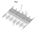
- FIG. 1 Shown is a bottom portion 2 of a cutlery drawer 14 for a dishwasher, not shown, which has a plurality of adjacently arranged in a row holding means 4, wherein the bottom portion 2 of the cutlery drawer 14 and the holding means 4 integrally formed, for example, from a suitable plastic are.
- Each two adjacent holding means 4 form a receiving space 16 by a cutlery 6, such as in the present embodiment, a knife 18 or a spoon or a fork, can be used.
- a row holding means 4 allow by their symmetrical design designed for holding both sides holding it with a minimum number of holding means 4 a maximum number of cutlery 6 during a rinsing process in a cutlery drawer 14 safely.
- the holding means 4 each have a mounting portion 8, 10 which is fixed to the bottom portion 2 of the cutlery drawer.
- the two fastening sections 8, 10 are connected to one another by an arcuate middle section 12, so that the two fastening sections 8, 10 and the middle section 12 have a kink-free, loop-shaped configuration.
- the two fastening portions 8, 10 and the central portion 12 have the same cross section, which is triangular.
- the two adjacently arranged holding elements 4 are arranged to each other so that the two fixing portions 8, 10 are arranged by the two holding means 4 on each side of a piece of cutlery to be held 6 and thus ensure that as in the illustrated embodiment, the inserted knife 18 on its cutting edge 20 of the blade 22 stops.
- the holding means 4 are arranged such that the edges formed by the triangular cross-section form holding surfaces for the inserted cutlery 6, so that the contact area between the edges and the cutlery 6 is minimized and is ensured so that the staining is reduced during a drying process.
- the insertion of a cutlery 6 is simplified because an operator when inserting can be oriented to the arcuate central portion 12 and the further insertion of the cutlery 6 of this by contact with the support surfaces forming mounting portions 8, 10 aligns itself, so that optimum space utilization is guaranteed.
Landscapes
- Washing And Drying Of Tableware (AREA)
Description
- Die Erfindung betrifft eine Besteckschublade für eine Geschirrspülmaschine, wenigstens umfassend einen Bodenabschnitt, an dem wenigstens ein Haltemittel zum Halten von Besteckteilen angeordnet ist.
- Aus der Druckschrift
DE 37 21 689 A1 ist eine Besteckschublade für eine Geschirrspülmaschine bekannt, die ausziehbar in einem Spülraum einer Geschirrspülmaschine angeordnet ist Um ein ungewolltes Verrutschen von Besteckteilen während eines Spülvorgangs auf die auftreffende Spülplatte zu verhindern, weist die Besteckschublade neben Auflagepunkten auch Haltemittel auf, die an dem Bodenabschnitt der Besteckschublade befestigt sind und sich in einem rechten Winkel stabförmig nach oben erstrecken und so seitliche Anlagenfläche bilden, die zum Halten von eingesetzten Besteckteilen dienen. Diese stabförmigen Haltemittel weisen jedoch eine geringe mechanische Stabilität auf und erschweren darüber hinaus das Einlegen von Besteckteilen, da hierfür eine genaue Positionierung der Besteckteile nötig ist, die seitens einer Bedienperson große Sorgfalt erfordert. - Eine ähnliche Ausbildung einer Besteckschublade für eine Geschirrspülmaschine mit einzelnen und aufragenden Haltedornen zeigt auch die Druckschrift
EP 0 186 157 A1 , von welcher aus die gleichen Probleme wie oben zu lösen sind. - Die Druckschrift
FR 2 643 809 A - Es ist daher Aufgabe der Erfindung, eine Besteckschublade für eine Geschirrspülmaschine derart weiterzubilden, dass die Bedienung vereinfacht ist.
- Die Aufgabe der Erfindung wird gelöst durch eine Besteckschublade für eine Geschirrspülmaschine, wenigstens umfassend einen Bodenabschnitt, an dem wenigstens Haltemittel zum Halten von Besteckteilen angeordnet sind, wobei die Besteckschublade dadurch gekennzeichnet ist, dass die Haltemittel wenigstens zwei Befestigungsabschnitte, mit denen die Haltemittel an dem Bodenabschnitt befestigt sind, und einen Mittelabschnitt, der die wenigstens zwei Befestigungsabschnitte miteinander verbindet, aufweisen und dass die wenigsten zwei Befestigungsabschnitte entlang einer Geraden angeordnet sind, die im Wesentlichen parallel zu einer Längsachse eines eingesetzten Besteckteils verläuft, so dass die wenigstens zwei Befestigungsabschnitte an zwei unterschiedlichen Abschnitten das eingesetzte Besteckteil halten. Somit wird zum einen die mechanische Stabilität der Haltemittel erhöht und andererseits die Positionierung von Besteckteilen vereinfacht, denn eine Bedienperson kann sich beim Einfügen von Besteckteilen einfach an dem Mittelabschnitt orientieren, wobei der die beiden Befestigungsabschnitte verbindende Mittelabschnitt die Stabilität der Haltemittel erhöht.
- Weiterhin gewährleistet die dargelegte Halterung des eingesetzten Besteckteils an zwei unterschiedlichen Abschnitten einen sicheren Halt während des Betriebs in der Geschirrspülmaschine und erlaubt es zugleich, die Kontaktflächen zwischen einem Besteckteil und den Haltemitteln zu reduzieren, um so einer ungewünschten Fleckenbildung beim Trocknen der Besteckteile entgegenzuwirken.
- In einer bevorzugten Ausführungsform ist vorgesehen, dass die wenigstens zwei Befestigungsabschnitte zum zweiseitigen Halten von Besteckteilen ausgebildet sind, das heißt, dass die Haltemittel, bestehend aus wenigstens zwei Befestigungsabschnitten und einem die Befestigungsabschnitte verbindenden Mittelabschnitt symmetrisch ausgebildet sind, und mit einem jeweils benachbart angeordneten Haltemittel zusammen wirken.
- Vorzugsweise ist vorgesehen, dass die wenigstens zwei Befestigungsabschnitte und der Mittelabschnitt einen gleichen Querschnitt aufweisen. Somit gehen die beiden Befestigungsabschnitte und der Mittelabschnitt übergangslos ineinander über, was einer unerwünschten Tropfenbildung beziehungsweise -anhaftung entgegenwirkt. Jedoch ist es auch möglich, die wenigstens zwei Befestigungsabschnitte und/oder den Mittelabschnitt unterschiedliche Querschnitte aufzuweisen.
- Die wenigstens zwei Befestigungsabschnitte und der Mittelabschnitt können einen beliebig geformten Querschnitt aufweisen, beispielsweise einen halbrunden oder halboval ausgebildeten Abschnitt. Ferner ist es denkbar, dass die wenigstens zwei Befestigungsabschnitte und der Mittelabschnitt einen viereckigen, fünfeckigen oder eine höhere Anzahl von Ecken aufweisenden Querschnitt aufweisen. Vorzugsweise ist jedoch vorgesehen, dass die wenigstens zwei Befestigungsabschnitte und der Mittelabschnitt einen dreieckigen Querschnitt aufweisen. Dabei sind die zwei Befestigungsabschnitte und der Mittelabschnitt derart angeordnet und ausgebildet, dass eingelegte Besteckteile an einer Kante des dreieckigen Querschnitts anliegen, so dass die Kontaktfläche minimiert ist und so eine Fleckenbildung weitestgehend unterbunden wird.
- Der Bodenabschnitt der Besteckschublade, die wenigstens zwei Befestigungsabschnitte und der Mittelabschnitt können aus einzelnen Bauelementen zusammengesetzt sein, die im Rahmen einer Montage zusammengeführt werden. Vorzugsweise ist jedoch vorgesehen, dass der Bodenabschnitt, die wenigstens zwei Befestigungsabschnitte und der Mittelabschnitt einstückig ausgebildet sind. Hierzu können der Bodenabschnitt der Besteckschublade, die wenigstens zwei Befestigungsabschnitte und der Mittelabschnitt aus einem geeigneten Kunststoff gefertigt sein, zum Beispiel mittels Spritzguss, wobei der Kunststoff entsprechend einem Einsatz in dem Inneren einer Geschirrspülmaschine entsprechend temperatur- und chemikalienresistent ist.
- Der Mittelabschnitt, der die wenigstens zwei Befestigungsabschnitte der Haltemittel miteinander verbindet, kann beliebig geformt, zum Beispiel Knicke aufweisend, geformt sein. Vorzugsweise ist jedoch vorgesehen, dass der Mittelabschnitt bogenförmig ausgebildet ist, sodass gewährleistet ist, dass Spülflotte während des Trocknungsprogramms problemlos und rückstandsfrei ablaufen kann.
- Ferner ist vorzugsweise vorgesehen, dass die Haltemittel schlaufenförmig ausgebildet sind, das heißt, dass die wenigstens zwei Befestigungsabschnitte und der Mittelabschnitt im Wesentlichen übergangslos beziehungsweise knickfrei hyperbelförmig ineinander übergehend ausgebildet sind.
- Dabei ist vorzugsweise vorgesehen, dass zwei Haltemittel zusammen eine Aufnahme für ein Besteckteil bilden, das heißt, ein Besteckteil wird von insgesamt vier Befestigungsabschnitten von zwei Haltemitteln während eines Spülvorganges gehalten und ist so gegen ein ungewolltes Verrutschen gesichert.
- Hierzu sind vorzugsweise die Haltemittel in wenigstens einer Reihe angeordnet, sodass die Haltemittel nebeneinander angeordnet sind und insbesondere die Haltemittel bis auf die an dem Reihenende angeordneten Haltemittel zum beidseitigem Halten von Besteckteilen ausgebildet sind, sodass mit einer minimalen Anzahl von Haltemitteln eine maximale Anzahl von Besteckteilen gehalten werden kann.
- Ferner gehört zu der Erfindung eine Geschirrspülmaschine, die wenigstens eine derartige Besteckschublade aufweist.
- Im Folgenden wird die unter Bezugnahme auf eine Zeichnung erläutert. Es zeigen:
- Fig. 1
- eine perspektivische Darstellung eines Abschnitts einer erfindungsgemäßen Besteckschublade;
- Fig. 2
- eine Vorderansicht eines erfindungsgemäßen Ausführungsbeispiels;
- Fig. 3
- eine Draufsicht auf ein erfindungsgemäßes Ausführungsbeispiel; und
- Fig. 4
- eine perspektivische Darstellung eines erfindungsgemäßen Ausführungsbeispiels der Erfindung.
- Es wird auf die
Fig. 1 bis 4 Bezug genommen. - Dargestellt ist ein Bodenabschnitt 2 einer Besteckschublade 14 für eine nicht dargestellte Geschirrspülmaschine, die eine Mehrzahl in einer Reihe benachbart zueinander angeordnete Haltemittel 4 aufweist, wobei der Bodenabschnitt 2 der Besteckschublade 14 und die Haltemittel 4 einstückig, beispielsweise aus einem geeigneten Kunststoff, gebildet sind. Je zwei benachbarte Haltemittel 4 bilden einen Aufnahmeraum 16, indem ein Besteckteil 6, wie zum Beispiel im vorliegenden Ausführungsbeispiel ein Messer 18 oder auch ein Löffel oder eine Gabel, eingesetzt werden kann.
- Dabei erlauben die in einer Reihe angeordneten Haltemittel 4 durch ihre symmetrische, zum beidseitigen Halten ausgebildete Ausgestaltung es, mit einer minimalen Anzahl von Haltemitteln 4 eine maximale Anzahl von Besteckteilen 6 während eines Spülvorganges in einer Besteckschublade 14 sicher zu halten.
- Die Haltemittel 4 weisen je einen Befestigungsabschnitt 8, 10 auf, der an dem Bodenabschnitt 2 der Besteckschublade befestigt ist. Die beiden Befestigungsabschnitte 8,10 sind durch einen bogenförmigen Mittelabschnitt 12 miteinander verbunden, sodass die zwei Befestigungsabschnitte 8, 10 und der Mittelabschnitt 12 eine knickfreie, schlaufenförmige Gestalt aufweisen. Dabei weisen die zwei Befestigungsabschnitte 8, 10 und der Mittelabschnitt 12 den gleichen Querschnitt auf, der dreieckig ausgebildet ist.
- Die zwei benachbart zueinander angeordnete Halteelemente 4 sind dabei so zueinander angeordnet, dass die zwei Befestigungsabschnitte 8, 10 von den beiden Haltemitteln 4 auf je einer Seite eines zu haltenden Besteckteils 6 angeordnet sind und so gewährleisten, dass wie im dargestellten Ausführungsbeispiel das eingesetzte Messer 18 auf seiner Schneide 20 der Klinge 22 stehen bleibt. Dabei sind die Haltemittel 4 derart angeordnet, dass die durch den dreieckigen Querschnitt gebildeten Kanten Halteflächen für das eingesetzte Besteckteil 6 bilden, sodass die Kontaktfläche zwischen den Kanten und dem Besteckteil 6 minimiert ist und so gewährleistet ist, dass die Fleckenbildung während eines Trockenvorgangs reduziert ist.
- Dabei wird das Einsetzen eines Besteckteils 6 vereinfacht, da einen Bedienperson bei Einsetzen sich an dem bogenförmig ausgebildeten Mittelabschnitt 12 orientieren kann und sich beim weiteren Einführen des Besteckteils 6 dieses durch Kontakt mit den Halteflächen bildenden Befestigungsabschnitten 8, 10 selbst ausrichtet, so dass eine optimale Raumausnutzung gewährleistet ist.
-
- 2
- Bodenabschnitt
- 4
- Haltemittel
- 6
- Besteckteil
- 8
- Befestigungsabschnitt
- 10
- Befestigungsabschnitt
- 12
- Mittelabschnitt
- 14
- Besteckschublade
- 16
- Aufnahmeraum
- 18
- Messer
- 20
- Schneide
- 22
- Klinge
Claims (11)
- Besteckschublade (14) für eine Geschirrspülmaschine, wenigstens umfassend einen Bodenabschnitt (2), an dem wenigstens ein Haltemittel (4) zum Halten von Besteckteilen (6) angeordnet ist, dadurch gekennzeichnet, dass die Haltemittel (4) wenigstens zwei Befestigungsabschnitte (8, 10), mit denen die Haltemittel an dem Bodenabschnitt (2) befestigt sind, und einen Mittelabschnitt (12), der die wenigstens zwei Befestigungsabschnitte (8, 10) miteinander verbindet, aufweisen und dass die wenigsten zwei Befestigungsabschnitte (8, 10) entlang einer Geraden angeordnet sind, die im Wesentlichen parallel zu einer Längsachse eines eingesetzten Besteckteils (6) verläuft, so dass die wenigstens zwei Befestigungsabschnitte (8, 10) an zwei unterschiedlichen Abschnitten das eingesetzte Besteckteil (6) halten.
- Besteckschublade (14) nach Anspruch 1, dadurch gekennzeichnet, dass die wenigstens zwei Befestigungsabschnitte (8, 10) zum Halten von einem Besteckteil (6) ausgebildet sind.
- Besteckschublade (14) nach Anspruch 1 oder 2, dadurch gekennzeichnet, dass die wenigstens zwei Befestigungsabschnitte (8, 10) zum zweiseitigen Halten von Besteckteilen (6) ausgebildet sind.
- Besteckschublade (14) nach einem der vorherigen Ansprüche, dadurch gekennzeichnet, dass die wenigstens zwei Befestigungsabschnitte (8, 10) und der Mittelabschnitt (12) einen gleichen Querschnitt aufweisen.
- Besteckschublade (14) nach einem der vorherigen Ansprüche, dadurch gekennzeichnet, dass die wenigstens zwei Befestigungsabschnitte (8, 10) und der Mittelabschnitt (12) einen dreieckigen Querschnitt aufweisen.
- Besteckschublade (14) nach einem der vorherigen Ansprüche, dadurch gekennzeichnet, dass der Bodenabschnitt (2), die wenigstens zwei Befestigungsabschnitte (8, 10) und der Mittelabschnitt (12) einstückig ausgebildet sind.
- Besteckschublade (14) nach einem der vorherigen Ansprüche, dadurch gekennzeichnet, dass der Mittelabschnitt (12) bogenförmig ausgebildet ist.
- Besteckschublade (14) nach einem der vorherigen Ansprüche, dadurch gekennzeichnet, dass die Haltemittel (4) schlaufenförmig ausgebildet sind.
- Besteckschublade (14) nach einem der vorherigen Ansprüche, dadurch gekennzeichnet, dass wenigstens zwei Haltemittel (4) eine Aufnahme für eine Besteckteil (6) bilden.
- Besteckschublade (14) nach einem der vorherigen Ansprüche, dadurch gekennzeichnet, dass die Haltemittel (4) in wenigstens einer Reihe angeordnet sind.
- Geschirrspülmaschine, die wenigstens eine Besteckschublade (14) nach einem der vorherigen Ansprüche aufweist.
Priority Applications (1)
| Application Number | Priority Date | Filing Date | Title |
|---|---|---|---|
| PL08735488T PL2134233T3 (pl) | 2007-04-11 | 2008-03-26 | Szuflada na sztućce dla zmywarki do naczyń |
Applications Claiming Priority (2)
| Application Number | Priority Date | Filing Date | Title |
|---|---|---|---|
| DE102007017115A DE102007017115A1 (de) | 2007-04-11 | 2007-04-11 | Besteckschublade für Geschirrspülmaschine |
| PCT/EP2008/053569 WO2008125448A1 (de) | 2007-04-11 | 2008-03-26 | Besteckschublade für geschirrspülmaschine |
Publications (2)
| Publication Number | Publication Date |
|---|---|
| EP2134233A1 EP2134233A1 (de) | 2009-12-23 |
| EP2134233B1 true EP2134233B1 (de) | 2014-05-21 |
Family
ID=39539480
Family Applications (1)
| Application Number | Title | Priority Date | Filing Date |
|---|---|---|---|
| EP08735488.2A Active EP2134233B1 (de) | 2007-04-11 | 2008-03-26 | Besteckschublade für geschirrspülmaschine |
Country Status (7)
| Country | Link |
|---|---|
| US (1) | US20100117498A1 (de) |
| EP (1) | EP2134233B1 (de) |
| CN (1) | CN101646378A (de) |
| DE (1) | DE102007017115A1 (de) |
| ES (1) | ES2471441T3 (de) |
| PL (1) | PL2134233T3 (de) |
| WO (1) | WO2008125448A1 (de) |
Families Citing this family (14)
| Publication number | Priority date | Publication date | Assignee | Title |
|---|---|---|---|---|
| DE102009000941A1 (de) * | 2009-02-17 | 2010-10-07 | BSH Bosch und Siemens Hausgeräte GmbH | Geschirrspülmaschine mit Spülguthalterung sowie Spülguthalterung |
| US20170143143A1 (en) * | 2010-01-15 | 2017-05-25 | Base4 Group, Inc. | Horizontal Knife Holder |
| EP2364636B2 (de) | 2010-03-12 | 2020-08-12 | Electrolux Home Products Corporation N.V. | Geschirrfach, Geschirrspülmaschinenkorb und Geschirrspülmaschine |
| US8348068B2 (en) * | 2010-03-18 | 2013-01-08 | Mark Huentelman | Cutting instrument rack |
| WO2014094894A1 (en) | 2012-12-21 | 2014-06-26 | Electrolux Home Products Corporation N. V. | Cutlery tray module for a dishwasher and dishwasher comprising at least one cutlery tray module |
| BR112015014767A2 (pt) | 2012-12-21 | 2017-07-11 | Electrolux Home Products Corp Nv | prateleira de talheres e máquina de lavar louça |
| USD779893S1 (en) * | 2014-05-19 | 2017-02-28 | Robert Welch Designs Ltd. | Knife insert for drawer |
| CN104188606A (zh) * | 2014-08-15 | 2014-12-10 | 侯舒婷 | 一种具有餐具托盘的洗碗机 |
| US10149595B2 (en) | 2016-11-07 | 2018-12-11 | Whirlpool Corporation | Utensil rack for a dishwasher |
| CN109946855A (zh) * | 2017-12-21 | 2019-06-28 | 青岛海尔洗碗机有限公司 | 眼镜架和洗碗机 |
| DE102018214238B3 (de) | 2018-08-23 | 2019-10-24 | BSH Hausgeräte GmbH | Dekorteil für ein wasserführendes Haushaltsgerät und wasserführendes Haushaltsgerät |
| KR102590134B1 (ko) | 2018-11-13 | 2023-10-18 | 삼성전자주식회사 | 랙 어셈블리 및 이를 갖는 식기세척기 |
| DE102021116816B4 (de) | 2021-06-30 | 2023-01-19 | Miele & Cie. Kg | Besteckschublade für eine Geschirrspülmaschine |
| DE102021214446A1 (de) | 2021-12-15 | 2023-06-15 | BSH Hausgeräte GmbH | Dekorteil für ein vorzugsweise wasserführendes Haushaltsgerät |
Family Cites Families (25)
| Publication number | Priority date | Publication date | Assignee | Title |
|---|---|---|---|---|
| US542734A (en) * | 1895-07-16 | Dish-drainer | ||
| DE632145C (de) * | 1933-04-26 | 1936-07-03 | Buchholz Geb | Besteckhalter aus Holz, Kunstharz oder aehnlichem Werkstoff |
| US2697525A (en) * | 1952-12-05 | 1954-12-21 | Wooster Rubber Company | Dish drainer |
| US2971652A (en) * | 1956-11-30 | 1961-02-14 | Waste King Corp | Dish rack |
| US2981267A (en) * | 1957-10-25 | 1961-04-25 | Gen Electric | Apparatus and method for sanitizing tableware |
| US2997155A (en) * | 1959-06-11 | 1961-08-22 | Southern Hotel And Restaurant | Rack construction for dishwashing machines |
| DE1212260B (de) * | 1962-04-04 | 1966-03-10 | Schineis O H G | Bestecketui |
| US3169641A (en) * | 1962-04-12 | 1965-02-16 | George S Chapman | Wire dish drainer with glass holding elements |
| US3182854A (en) * | 1962-08-23 | 1965-05-11 | Gen Electric | Silverware basket for dishwasher |
| US3203557A (en) * | 1963-06-14 | 1965-08-31 | Jr Ralph Ettlinger | Tray and dish rack assembly |
| US3289683A (en) * | 1966-06-29 | 1966-12-06 | Betty B Tomlin | Rack structure for a dishwashing machine |
| US4577764A (en) * | 1984-07-09 | 1986-03-25 | American Sterilizer Company | Wire rack for processing hard container systems in washing-sterilizers |
| DE3447302A1 (de) * | 1984-12-24 | 1986-06-26 | Miele & Cie GmbH & Co, 4830 Gütersloh | Geschirrspuelmaschine fuer den haushalt |
| DE3721689A1 (de) * | 1987-07-01 | 1989-01-12 | Miele & Cie | Besteckkorb fuer eine geschirrspuelmaschine |
| US4848217A (en) * | 1988-03-04 | 1989-07-18 | Moerke Display & Mfg. Co., Inc. | Multipurpose cooking rack |
| US4836392A (en) * | 1988-12-23 | 1989-06-06 | Constantino Cynthia L | Upright baby-nipple sanitizer |
| FR2643809B1 (fr) | 1989-03-03 | 1992-02-07 | Esswein Sa | Accessoire amovible pour lave-vaisselle |
| FR2717669B1 (fr) * | 1994-03-25 | 1996-06-14 | Deglon Ets Jean | Dispositif pour le rangement d'accessoires culinaires ou d'outillage. |
| US5649630A (en) * | 1995-03-01 | 1997-07-22 | White Consolidated Industries, Inc. | Multi-functional dish holder |
| US5924433A (en) * | 1997-03-19 | 1999-07-20 | Whirlpool Corporation | Gas injection plastic molding applied to a dishwasher tub |
| DE19736793C2 (de) * | 1997-08-23 | 2000-04-06 | Whirlpool Co | Geschirrkorb für eine Geschirrspülmaschine |
| DE19820979A1 (de) * | 1998-05-12 | 1999-11-18 | Aeg Hausgeraete Gmbh | Geschirrspülmaschine mit einer Besteckablage |
| US6269961B1 (en) * | 2000-01-14 | 2001-08-07 | M. Kamenstein, Inc. | Foldable support rack |
| US6571965B1 (en) * | 2000-04-12 | 2003-06-03 | Whirlpool Corporation | Dishwasher rack with pivotable fences |
| DE10056487A1 (de) * | 2000-11-15 | 2002-05-23 | Bsh Bosch Siemens Hausgeraete | Einsatz für einen Geschirrkorb einer Geschirrspülmaschine |
-
2007
- 2007-04-11 DE DE102007017115A patent/DE102007017115A1/de not_active Withdrawn
-
2008
- 2008-03-26 WO PCT/EP2008/053569 patent/WO2008125448A1/de not_active Ceased
- 2008-03-26 CN CN200880010415A patent/CN101646378A/zh active Pending
- 2008-03-26 ES ES08735488.2T patent/ES2471441T3/es active Active
- 2008-03-26 EP EP08735488.2A patent/EP2134233B1/de active Active
- 2008-03-26 US US12/594,377 patent/US20100117498A1/en not_active Abandoned
- 2008-03-26 PL PL08735488T patent/PL2134233T3/pl unknown
Also Published As
| Publication number | Publication date |
|---|---|
| ES2471441T3 (es) | 2014-06-26 |
| WO2008125448A1 (de) | 2008-10-23 |
| EP2134233A1 (de) | 2009-12-23 |
| CN101646378A (zh) | 2010-02-10 |
| DE102007017115A1 (de) | 2008-10-16 |
| US20100117498A1 (en) | 2010-05-13 |
| PL2134233T3 (pl) | 2014-10-31 |
Similar Documents
| Publication | Publication Date | Title |
|---|---|---|
| WO2008125448A1 (de) | Besteckschublade für geschirrspülmaschine | |
| DE102011080698B4 (de) | Spülgutträger zur variablen Aufnahme von Spülgut | |
| EP1773174B1 (de) | Geschirrkorb zur variablen aufnahme von geschirrteilen | |
| WO2013020811A1 (de) | Geschirrspülmaschine mit mindestens einer mit anordnungshinweisen versehenen spülgut-aufnahmestruktur | |
| DE102007057510B4 (de) | Geschirrkorb zur Aufnahme von Spülgut mit mindestens einem korbbodenseitigen Stützelement zur Abstützung eines verschiebbaren Geschirrkorb-Einsatzes | |
| DE20213439U1 (de) | Kühlschrank, Kühlschrankregalmontageelement und Rückhalteelement für Gegenstände | |
| EP4076126B1 (de) | Spülgutaufnahme | |
| DE102014201027B4 (de) | Aufnahmevorrichtung, Spülgutaufnahme und wasserführendes Haushaltsgerät | |
| EP2271248B1 (de) | Geschirrkorb und geschirrspülmaschine | |
| DE19540610C2 (de) | Ablage für einen Geschirrkorb einer Haushalt-Geschirrspülmaschine | |
| EP4362762B1 (de) | Besteckschublade für eine geschirrspülmaschine | |
| DE102012016762B4 (de) | Geschirrspülmaschine | |
| EP3090677B1 (de) | Besteckschublade für eine geschirrspülmaschine | |
| DE102011053497B4 (de) | Besteckschublade für eine Geschirrspülmaschine | |
| DE10347973A1 (de) | Vorrichtung zur Besteckablage in Geschirrspülern | |
| EP3175763A1 (de) | Geschirrkorb, insbesondere besteckschublade | |
| EP2984980B1 (de) | Spülgutaufnahme einer geschirrspülmaschine | |
| EP4117499B1 (de) | Besteckschublade für eine geschirrspülmaschine | |
| EP3175764A1 (de) | Geschirrkorb, insbesondere besteckschublade | |
| DE102009014695B4 (de) | Korb für eine Geschirrspülmaschine | |
| DE202009002877U1 (de) | Messerhalter, insbesondere für Schlacht- und Zerlegebetriebe | |
| DE20122599U1 (de) | Vorrichtung zum Ablegen von Spülgut in einer Geschirrspülmaschine | |
| DE102006055351A1 (de) | Besteckaufnahme für zu spülende Besteckteile | |
| DE202024107626U1 (de) | Halter zum Halten von Spülgut in einem Geschirrkorb einer Haushalts-Geschirrspülmaschine und Haushalts-Geschirrspülmaschine mit einem solchen Halter | |
| DE102019120102A1 (de) | Geschirrhalter insbesondere für eine Geschirrspülmaschine |
Legal Events
| Date | Code | Title | Description |
|---|---|---|---|
| PUAI | Public reference made under article 153(3) epc to a published international application that has entered the european phase |
Free format text: ORIGINAL CODE: 0009012 |
|
| 17P | Request for examination filed |
Effective date: 20091111 |
|
| AK | Designated contracting states |
Kind code of ref document: A1 Designated state(s): AT BE BG CH CY CZ DE DK EE ES FI FR GB GR HR HU IE IS IT LI LT LU LV MC MT NL NO PL PT RO SE SI SK TR |
|
| DAX | Request for extension of the european patent (deleted) | ||
| 17Q | First examination report despatched |
Effective date: 20101006 |
|
| RIC1 | Information provided on ipc code assigned before grant |
Ipc: A47B 88/20 20060101ALI20131113BHEP Ipc: A47L 15/50 20060101AFI20131113BHEP |
|
| GRAP | Despatch of communication of intention to grant a patent |
Free format text: ORIGINAL CODE: EPIDOSNIGR1 |
|
| INTG | Intention to grant announced |
Effective date: 20140109 |
|
| GRAS | Grant fee paid |
Free format text: ORIGINAL CODE: EPIDOSNIGR3 |
|
| GRAA | (expected) grant |
Free format text: ORIGINAL CODE: 0009210 |
|
| AK | Designated contracting states |
Kind code of ref document: B1 Designated state(s): AT BE BG CH CY CZ DE DK EE ES FI FR GB GR HR HU IE IS IT LI LT LU LV MC MT NL NO PL PT RO SE SI SK TR |
|
| REG | Reference to a national code |
Ref country code: GB Ref legal event code: FG4D Free format text: NOT ENGLISH |
|
| REG | Reference to a national code |
Ref country code: CH Ref legal event code: EP |
|
| REG | Reference to a national code |
Ref country code: AT Ref legal event code: REF Ref document number: 669168 Country of ref document: AT Kind code of ref document: T Effective date: 20140615 |
|
| REG | Reference to a national code |
Ref country code: IE Ref legal event code: FG4D Free format text: LANGUAGE OF EP DOCUMENT: GERMAN |
|
| REG | Reference to a national code |
Ref country code: ES Ref legal event code: FG2A Ref document number: 2471441 Country of ref document: ES Kind code of ref document: T3 Effective date: 20140626 |
|
| REG | Reference to a national code |
Ref country code: DE Ref legal event code: R096 Ref document number: 502008011798 Country of ref document: DE Effective date: 20140703 |
|
| REG | Reference to a national code |
Ref country code: NL Ref legal event code: VDEP Effective date: 20140521 |
|
| REG | Reference to a national code |
Ref country code: LT Ref legal event code: MG4D |
|
| PG25 | Lapsed in a contracting state [announced via postgrant information from national office to epo] |
Ref country code: IS Free format text: LAPSE BECAUSE OF FAILURE TO SUBMIT A TRANSLATION OF THE DESCRIPTION OR TO PAY THE FEE WITHIN THE PRESCRIBED TIME-LIMIT Effective date: 20140921 Ref country code: NO Free format text: LAPSE BECAUSE OF FAILURE TO SUBMIT A TRANSLATION OF THE DESCRIPTION OR TO PAY THE FEE WITHIN THE PRESCRIBED TIME-LIMIT Effective date: 20140821 Ref country code: FI Free format text: LAPSE BECAUSE OF FAILURE TO SUBMIT A TRANSLATION OF THE DESCRIPTION OR TO PAY THE FEE WITHIN THE PRESCRIBED TIME-LIMIT Effective date: 20140521 Ref country code: LT Free format text: LAPSE BECAUSE OF FAILURE TO SUBMIT A TRANSLATION OF THE DESCRIPTION OR TO PAY THE FEE WITHIN THE PRESCRIBED TIME-LIMIT Effective date: 20140521 Ref country code: GR Free format text: LAPSE BECAUSE OF FAILURE TO SUBMIT A TRANSLATION OF THE DESCRIPTION OR TO PAY THE FEE WITHIN THE PRESCRIBED TIME-LIMIT Effective date: 20140822 |
|
| REG | Reference to a national code |
Ref country code: PL Ref legal event code: T3 |
|
| PG25 | Lapsed in a contracting state [announced via postgrant information from national office to epo] |
Ref country code: HR Free format text: LAPSE BECAUSE OF FAILURE TO SUBMIT A TRANSLATION OF THE DESCRIPTION OR TO PAY THE FEE WITHIN THE PRESCRIBED TIME-LIMIT Effective date: 20140521 Ref country code: SE Free format text: LAPSE BECAUSE OF FAILURE TO SUBMIT A TRANSLATION OF THE DESCRIPTION OR TO PAY THE FEE WITHIN THE PRESCRIBED TIME-LIMIT Effective date: 20140521 Ref country code: LV Free format text: LAPSE BECAUSE OF FAILURE TO SUBMIT A TRANSLATION OF THE DESCRIPTION OR TO PAY THE FEE WITHIN THE PRESCRIBED TIME-LIMIT Effective date: 20140521 |
|
| PG25 | Lapsed in a contracting state [announced via postgrant information from national office to epo] |
Ref country code: PT Free format text: LAPSE BECAUSE OF FAILURE TO SUBMIT A TRANSLATION OF THE DESCRIPTION OR TO PAY THE FEE WITHIN THE PRESCRIBED TIME-LIMIT Effective date: 20140922 |
|
| PG25 | Lapsed in a contracting state [announced via postgrant information from national office to epo] |
Ref country code: RO Free format text: LAPSE BECAUSE OF FAILURE TO SUBMIT A TRANSLATION OF THE DESCRIPTION OR TO PAY THE FEE WITHIN THE PRESCRIBED TIME-LIMIT Effective date: 20140521 Ref country code: CZ Free format text: LAPSE BECAUSE OF FAILURE TO SUBMIT A TRANSLATION OF THE DESCRIPTION OR TO PAY THE FEE WITHIN THE PRESCRIBED TIME-LIMIT Effective date: 20140521 Ref country code: SK Free format text: LAPSE BECAUSE OF FAILURE TO SUBMIT A TRANSLATION OF THE DESCRIPTION OR TO PAY THE FEE WITHIN THE PRESCRIBED TIME-LIMIT Effective date: 20140521 Ref country code: EE Free format text: LAPSE BECAUSE OF FAILURE TO SUBMIT A TRANSLATION OF THE DESCRIPTION OR TO PAY THE FEE WITHIN THE PRESCRIBED TIME-LIMIT Effective date: 20140521 Ref country code: DK Free format text: LAPSE BECAUSE OF FAILURE TO SUBMIT A TRANSLATION OF THE DESCRIPTION OR TO PAY THE FEE WITHIN THE PRESCRIBED TIME-LIMIT Effective date: 20140521 |
|
| REG | Reference to a national code |
Ref country code: DE Ref legal event code: R097 Ref document number: 502008011798 Country of ref document: DE |
|
| PG25 | Lapsed in a contracting state [announced via postgrant information from national office to epo] |
Ref country code: NL Free format text: LAPSE BECAUSE OF FAILURE TO SUBMIT A TRANSLATION OF THE DESCRIPTION OR TO PAY THE FEE WITHIN THE PRESCRIBED TIME-LIMIT Effective date: 20140521 |
|
| REG | Reference to a national code |
Ref country code: CH Ref legal event code: PFA Owner name: BSH HAUSGERAETE GMBH, DE Free format text: FORMER OWNER: BSH BOSCH UND SIEMENS HAUSGERAETE GMBH, DE |
|
| REG | Reference to a national code |
Ref country code: FR Ref legal event code: PLFP Year of fee payment: 8 |
|
| RAP2 | Party data changed (patent owner data changed or rights of a patent transferred) |
Owner name: BSH HAUSGERAETE GMBH |
|
| PLBE | No opposition filed within time limit |
Free format text: ORIGINAL CODE: 0009261 |
|
| STAA | Information on the status of an ep patent application or granted ep patent |
Free format text: STATUS: NO OPPOSITION FILED WITHIN TIME LIMIT |
|
| 26N | No opposition filed |
Effective date: 20150224 |
|
| REG | Reference to a national code |
Ref country code: DE Ref legal event code: R081 Ref document number: 502008011798 Country of ref document: DE Owner name: BSH HAUSGERAETE GMBH, DE Free format text: FORMER OWNER: BSH BOSCH UND SIEMENS HAUSGERAETE GMBH, 81739 MUENCHEN, DE Effective date: 20150408 |
|
| REG | Reference to a national code |
Ref country code: DE Ref legal event code: R097 Ref document number: 502008011798 Country of ref document: DE Effective date: 20150224 |
|
| REG | Reference to a national code |
Ref country code: ES Ref legal event code: PC2A Owner name: BSH HAUSGERATE GMBH Effective date: 20150529 |
|
| PG25 | Lapsed in a contracting state [announced via postgrant information from national office to epo] |
Ref country code: SI Free format text: LAPSE BECAUSE OF FAILURE TO SUBMIT A TRANSLATION OF THE DESCRIPTION OR TO PAY THE FEE WITHIN THE PRESCRIBED TIME-LIMIT Effective date: 20140521 |
|
| PG25 | Lapsed in a contracting state [announced via postgrant information from national office to epo] |
Ref country code: LU Free format text: LAPSE BECAUSE OF FAILURE TO SUBMIT A TRANSLATION OF THE DESCRIPTION OR TO PAY THE FEE WITHIN THE PRESCRIBED TIME-LIMIT Effective date: 20150326 Ref country code: MC Free format text: LAPSE BECAUSE OF FAILURE TO SUBMIT A TRANSLATION OF THE DESCRIPTION OR TO PAY THE FEE WITHIN THE PRESCRIBED TIME-LIMIT Effective date: 20140521 |
|
| REG | Reference to a national code |
Ref country code: CH Ref legal event code: PL |
|
| GBPC | Gb: european patent ceased through non-payment of renewal fee |
Effective date: 20150326 |
|
| REG | Reference to a national code |
Ref country code: FR Ref legal event code: CD Owner name: BSH HAUSGERATE GMBH, DE Effective date: 20151022 |
|
| REG | Reference to a national code |
Ref country code: IE Ref legal event code: MM4A |
|
| PG25 | Lapsed in a contracting state [announced via postgrant information from national office to epo] |
Ref country code: CH Free format text: LAPSE BECAUSE OF NON-PAYMENT OF DUE FEES Effective date: 20150331 Ref country code: IE Free format text: LAPSE BECAUSE OF NON-PAYMENT OF DUE FEES Effective date: 20150326 Ref country code: GB Free format text: LAPSE BECAUSE OF NON-PAYMENT OF DUE FEES Effective date: 20150326 Ref country code: LI Free format text: LAPSE BECAUSE OF NON-PAYMENT OF DUE FEES Effective date: 20150331 |
|
| REG | Reference to a national code |
Ref country code: FR Ref legal event code: PLFP Year of fee payment: 9 |
|
| REG | Reference to a national code |
Ref country code: AT Ref legal event code: MM01 Ref document number: 669168 Country of ref document: AT Kind code of ref document: T Effective date: 20150326 |
|
| PG25 | Lapsed in a contracting state [announced via postgrant information from national office to epo] |
Ref country code: AT Free format text: LAPSE BECAUSE OF NON-PAYMENT OF DUE FEES Effective date: 20150326 |
|
| PG25 | Lapsed in a contracting state [announced via postgrant information from national office to epo] |
Ref country code: MT Free format text: LAPSE BECAUSE OF FAILURE TO SUBMIT A TRANSLATION OF THE DESCRIPTION OR TO PAY THE FEE WITHIN THE PRESCRIBED TIME-LIMIT Effective date: 20140521 |
|
| REG | Reference to a national code |
Ref country code: FR Ref legal event code: PLFP Year of fee payment: 10 |
|
| PG25 | Lapsed in a contracting state [announced via postgrant information from national office to epo] |
Ref country code: HU Free format text: LAPSE BECAUSE OF FAILURE TO SUBMIT A TRANSLATION OF THE DESCRIPTION OR TO PAY THE FEE WITHIN THE PRESCRIBED TIME-LIMIT; INVALID AB INITIO Effective date: 20080326 Ref country code: BG Free format text: LAPSE BECAUSE OF FAILURE TO SUBMIT A TRANSLATION OF THE DESCRIPTION OR TO PAY THE FEE WITHIN THE PRESCRIBED TIME-LIMIT Effective date: 20140521 |
|
| PG25 | Lapsed in a contracting state [announced via postgrant information from national office to epo] |
Ref country code: CY Free format text: LAPSE BECAUSE OF FAILURE TO SUBMIT A TRANSLATION OF THE DESCRIPTION OR TO PAY THE FEE WITHIN THE PRESCRIBED TIME-LIMIT Effective date: 20140521 |
|
| PG25 | Lapsed in a contracting state [announced via postgrant information from national office to epo] |
Ref country code: BE Free format text: LAPSE BECAUSE OF NON-PAYMENT OF DUE FEES Effective date: 20150331 |
|
| REG | Reference to a national code |
Ref country code: FR Ref legal event code: PLFP Year of fee payment: 11 |
|
| PGFP | Annual fee paid to national office [announced via postgrant information from national office to epo] |
Ref country code: ES Payment date: 20250416 Year of fee payment: 18 |
|
| PGFP | Annual fee paid to national office [announced via postgrant information from national office to epo] |
Ref country code: IT Payment date: 20250331 Year of fee payment: 18 |
|
| PGFP | Annual fee paid to national office [announced via postgrant information from national office to epo] |
Ref country code: DE Payment date: 20260331 Year of fee payment: 19 |
|
| PGFP | Annual fee paid to national office [announced via postgrant information from national office to epo] |
Ref country code: FR Payment date: 20260325 Year of fee payment: 19 |
|
| PGFP | Annual fee paid to national office [announced via postgrant information from national office to epo] |
Ref country code: TR Payment date: 20260324 Year of fee payment: 19 |
|
| PGFP | Annual fee paid to national office [announced via postgrant information from national office to epo] |
Ref country code: PL Payment date: 20260313 Year of fee payment: 19 |