EP2132391B1 - Treibstangenanordnung mit mindestens einer treibstange und mindestens einem treibstangenführungselement - Google Patents
Treibstangenanordnung mit mindestens einer treibstange und mindestens einem treibstangenführungselement Download PDFInfo
- Publication number
- EP2132391B1 EP2132391B1 EP08734630A EP08734630A EP2132391B1 EP 2132391 B1 EP2132391 B1 EP 2132391B1 EP 08734630 A EP08734630 A EP 08734630A EP 08734630 A EP08734630 A EP 08734630A EP 2132391 B1 EP2132391 B1 EP 2132391B1
- Authority
- EP
- European Patent Office
- Prior art keywords
- driving rod
- drive rod
- guide slot
- arrangement according
- web
- Prior art date
- Legal status (The legal status is an assumption and is not a legal conclusion. Google has not performed a legal analysis and makes no representation as to the accuracy of the status listed.)
- Active
Links
Images

Classifications
-
- E—FIXED CONSTRUCTIONS
- E05—LOCKS; KEYS; WINDOW OR DOOR FITTINGS; SAFES
- E05C—BOLTS OR FASTENING DEVICES FOR WINGS, SPECIALLY FOR DOORS OR WINDOWS
- E05C9/00—Arrangements of simultaneously actuated bolts or other securing devices at well-separated positions on the same wing
- E05C9/18—Details of fastening means or of fixed retaining means for the ends of bars
- E05C9/1825—Fastening means
- E05C9/1833—Fastening means performing sliding movements
- E05C9/185—Fastening means performing sliding movements parallel with actuating bar
-
- E—FIXED CONSTRUCTIONS
- E05—LOCKS; KEYS; WINDOW OR DOOR FITTINGS; SAFES
- E05C—BOLTS OR FASTENING DEVICES FOR WINGS, SPECIALLY FOR DOORS OR WINDOWS
- E05C9/00—Arrangements of simultaneously actuated bolts or other securing devices at well-separated positions on the same wing
- E05C9/22—Guides for sliding bars, rods or cables
Definitions
- the invention relates to a drive rod assembly for a window, a door or the like, with at least one drive rod and at least one driving rod guide element for holding the drive rod within a displacement range of the drive rod, wherein the drive rod guide element engages with a fastening web a guide slot of the drive rod and with a holding web an upper side of the Drive rod overlaps.
- the EP 1 728 946 A1 a drive rod assembly with a drive rod having a guide slot in a displacement region of the drive rod, which is penetrated by a fastening web of a drive rod guide element.
- the drive rod guide member is attached to a sash and holds the drive rod to the sash by means of a top of the drive rod, so the technological side of the sash frame side of the drive rod, spanning holding web.
- the drive rod is usually associated with a locking bolt, which cooperates with a strike plate, which is fixed to the frame of the window, the door or the like, so by displacement of the drive rod by means of the locking bolt and the strike plate, the window, the door or the like is locked or unlocked.
- the invention has for its object to provide a drive rod assembly, in a simple and cost-effective manner allows easy displacement of the drive rod within its displacement range.
- the cross section of the drive rod is profiled at least in the (espagnolette) displacement area such that there is only one line contact or several line contacts when the retaining bar and the drive rod come into contact. It is therefore intended that the drive rod has a profiled cross-section in the displacement region, which only allows the occurrence of one or more line contacts between the holding web and the drive rod at a contact.
- the drive rod is held or guided only by line contacts on the drive rod guide element. Due to the line contact or the line contacts only a slight friction between the drive rod guide member and the drive rod, so that the drive rod can be particularly easily shift within its displacement range or can be moved.
- the effect on a control handle for displacing the drive rod arrangement retroactive, due to the line contact / the line contacts, low frictional forces allow a user who operates the control handle, with little effort to displace the drive rod.
- the profiling of the drive rod in (espagnolette) displacement area is designed such that there is only one line contact or multiple line contacts at a touch of the mounting bar of the drive rod guide element and the drive rod.
- this is so also only one line contact or multiple line contacts before, so the drive rod is advantageously guided and held by the drive rod guide element.
- the profiling of the drive rod in the displacement region is preferably produced in the embossing process, in particular in the stamping process.
- the drive rod is therefore a drive rod profiled by a mechanical forming process.
- the upper side of the drive rod extends in the displacement region of its respective outer edge to the respective guide slot edge of the guide slot obliquely inclined, in particular obliquely inclined sloping.
- the profile of the drive rod is defined here by the contour of the top of the drive rod in the displacement area. Due to the guide slot, the drive rod has two outer edges, of which the upper side of the drive rod leads to a respective guide slot edge, that is an edge limiting the slot of the drive rod.
- the upper side of the respective outer edge to the guide slot edge or in other words from outside to inside, obliquely inclined, a line contact between the drive rod and the holding web of the driving rod guide element is ensured in a simple manner, provided, of course the retaining bar is not profiled accordingly.
- the upper side runs obliquely from the respective outer edge inclined to the respective guide slot edge. Seen in cross-section, this means that the upper side of the drive rod is recessed to the guide slot or towards the center.
- the upper side can run straight and / or arcuately from the respective outer edge to the respective guide slot edge.
- a substantially wedge-shaped free space is formed on both sides of the guide slot between the underside of the holding web and the top of the drive rod.
- the clearance ensures on the one hand in a simple manner, the advantageous line contact between holding web and drive rod and on the other hand, it allows a deformation, elastic and / or plastic, of the holding web without the line contact or the line contacts are lost.
- the driving rod guide element can be immersed in the groove bottom, whereby a larger tolerance range of the sash is allowed, in particular plastic deformation can be compensated in the window made of wood or plastic.
- the wedge-shaped free space is formed by the above-described embodiment of the upper side of the drive rod in the displacement region.
- a guide slot wall of the guide slot extends obliquely inclined between the guide slot edge on the upper side and the guide slot edge on the underside of the drive rod, in particular converging towards the attachment web of the drive rod guide element in the direction of the retaining web.
- the guide slot has, in addition to the guide slot edge on the top of the drive rod, as described above, of course, a guide slot edge on the underside of the drive rod.
- the guide slot wall can run straight and / or arcuate.
- a substantially wedge-shaped empty space is formed between the respective guide slot wall and the attachment web of the drive rod guide element. This allows, as the space described above, a resilient and / or plastic deformation of the drive rod in the displacement area and / or the driving rod guide element, without the line contact is lost.
- the wedge-shaped empty space is preferably defined by the profiling of the drive rod in the displacement region, ie the course of the guide slot walls of the guide slot.
- the retaining bar engages the front longitudinal sides of the drive rod with angled retaining lugs, which serve to support the plastic deformation of the groove bottom. From the outer edge of the top of the drive rod to the outer edge of the underside of the drive rod run the front long sides of the drive rod. By embracing the front long sides with angled retaining lugs of the retaining web an additional guidance of the drive rod is provided on the driving rod guide element.
- the fastening web of the driving rod guide element is penetrated by at least one screw receiving channel.
- a screw can be inserted, which serves for securing the drive rod guide element and thus the drive rod to, for example, a frame of a window, a door or the like.
- the screw receiving channel has at its pointing to the top of the retaining web end a cross-sectional widening, which serves to receive a screw head, so that the latter can be "sunk" in the driving rod guide member during assembly.
- the drive rod is formed tapered in the displacement region, so that the retaining lugs of the retaining web are received by the recesses forming the taper of the drive rod. The drive rod assembly is thus kept narrow overall and has no laterally projecting elements that could interfere with the operation on.
- the drive rod is a stamped sheet metal part, in particular a stamped sheet metal part. This forms a cheap and easy production possibility for the drive rod.
- the driving rod guide element is a molded part or die-cast part. Preferably, the driving rod guide element made of plastic or metal.
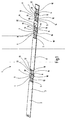
- the FIG. 1 shows in a perspective view of a drive rod assembly 1.
- the drive rod assembly 1 has a drive rod 2 forming stamped sheet metal part 3, which is held by three espagnolette guide elements 4, for example, to a sash of a window, a door or the like.
- the drive rod 2 a plurality of aligned in the longitudinal extension of the drive rod 2, formed in the drive rod 2 guide slots 5 through which a respective attachment web 6 of a drive rod guide element 4 engages.
- Each driving rod guide element 4 has, in addition to the fastening web, a retaining web 7 which is arranged substantially perpendicularly to the fastening web and which traverses an upper side 8 of the driving rod 2.
- each driving rod guide element 4 is penetrated by a screw receiving channel 9.
- a screw from the holding web side of the drive rod guide member 4 guided in the screw receiving channel 4 and screwed into the sash.
- the slot guides 5 of the drive rod 2 define a (espagnolette) displacement region 10, within which the drive rod 2 (along its longitudinal extent) can be displaced.
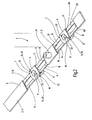
- FIG. 2 shows the drive rod assembly 1 of FIG. 1 enlarged in the region of a locking pin 11.
- the top 8 of the drive rod 2 is in the displacement region 10, which is defined by the longitudinal extent of the slit opening 12 formed slot guide 5, profiled such that the top 8 sloping sloping at its respective outer edge 13, 14 to a respective guide slot edge 15, 16 out inclined.
- the displacement region 10 is also formed tapered.
- Each holding web 7 of the driving rod guide elements 4 surrounds the drive rod 2 with angled retaining lugs 17, 18.
- the retaining lugs 17, 18 surround the outer edges 13, 14 of the drive rod 2 in the tapered displacement region 10 of the drive rod second
- FIG. 3 shows a cross section of the drive rod assembly 1 in the region of a drive rod guide member 4.
- the holding web 7 and the mounting bar 6 are integrally formed with each other, so that the drive rod guide member 4 is formed substantially T-shaped.
- the holding web 7 and the drive rod 2 are formed profiled in the displacement region such that between a bottom 19 of the retaining web 7 and the upper side 8 of the drive rod 2 on both sides of the slot guide 5, a substantially wedge-shaped free space 20 is formed, which tapers to the outside.
- the free space 20 is formed by the fact that the upper side 8 of the drive rod 2 in the displacement region 10, as described above, extends obliquely sloping from one outer edge 13, 14 to the respective guide slot edge 15, 16. Due to the advantageous profiling is only a line contact, namely along the outer edges 13 and / or 14 in front of a contact between the driving rod guide element 4 and the upper side 8 of the drive rod.
- the guide slot 5 further has two guide slot walls 21, 22, each extending from the guide slot edge 15 or 16 at the top 8 of the drive rod 2 to a guide slot edge 23, 24 on the underside 25 of the drive rod 2.
- the guide slot walls 21 and 22 converge to the fastening web 6.
- a substantially wedge-shaped empty space 26 is created between the guide slot walls 21, 22 and the fastening web 6.
- the retaining lugs 17 and 18 surround the drive rod 2 in the displacement region 10 such that a substantially wedge-shaped clearance space 31 is formed between the respective inner side 27, 28 of the retaining lugs 17, 18 and the associated end longitudinal sides 29, 30 or end wall of the drive rod 2.
- the present advantageous embodiment of the drive rod assembly 1 ensures that arise in a contact between the drive rod 2 and drive rod guide element 4 only one or more line contacts. If in addition, for example during assembly, the drive rod guide element 4 is deformed, the advantageous profiling of the drive rod 2 in the Verlagerüngs Society 10 or the free spaces 20, voids 26 and spacer spaces 31, an elastic and / or plastic deformation of the drive rod guide element 4 and / or Drive rod 2 to a certain extent, without losing the exclusive line contact.
- the driving rod guide element 4 is fastened to a casement by means of a screw which is inserted through the receiving channel 9, line contact is ensured even with a high torque when the screw is screwed in, so that the drive rod 2 can be displaced easily within its displacement region 10 despite high tightening forces.
- the holding web 7 and the drive rod 2 each have two unlocking openings 32, 33 which correspond to one another in a certain position of a drive rod guide element 4 in the displacement area 10, so that, for example, a pin can be inserted through both openings 32, 33, whereby the drive rod guide element the drive rod 2 is locked or preassembled / aligned before the actual mounting on the casement.
- the openings 32 and 33 thus serve as centering 34 or mounting aid 35th
Landscapes
- Engineering & Computer Science (AREA)
- Mechanical Engineering (AREA)
- Power-Operated Mechanisms For Wings (AREA)
- Window Of Vehicle (AREA)
- Lens Barrels (AREA)
- Closing And Opening Devices For Wings, And Checks For Wings (AREA)
Description
- Die Erfindung betrifft eine Treibstangenanordnung für ein Fenster, eine Tür oder dergleichen, mit mindestens einer Treibstange und mindestens einem Treibstangenführungselement zum Halten der Treibstange innerhalb eines Verlagerungsbereichs der Treibstange, wobei das Treibstangenführungselement mit einem Befestigungsteg einen Führungsschlitz der Treibstange durchgreift und mit einem Haltesteg eine Oberseite der Treibstange überfängt.
- Aus dem Stand der Technik sind Treibstangenanordnungen der eingangs genannten Art bekannt. So offenbart beispielsweise die
EP 1 728 946 A1 eine Treibstangenanordnung mit einer Treibstange, die in einem Verlagerungsbereich der Treibstange einen Führungsschlitz aufweist, der von einem Befestigungssteg eines Treibstangenführungselements durchgriffen wird. Das Treibstangenführungselement ist an einem Flügelrahmen befestigt und hält die Treibstange an dem Flügelrahmen mittels eines die Oberseite der Treibstange, also die vom Flügelrahmen wegweisende Seite der Treibstange, überfangenden Haltestegs. - Der Treibstange ist dabei in der Regel ein Schließbolzen zugeordnet, der mit einem Schließblech, welches fest am Blendrahmen des Fensters, der Tür oder dergleichen angeordnet ist, zusammenwirkt, sodass durch Verlagerung der Treibstange mittels des Schließbolzens und des Schließblechs das Fenster, die Tür oder dergleichen ver- oder entriegelt wird.
- Der Erfindung liegt die Aufgabe zugrunde, eine Treibstangenanordnung zu schaffen, die auf einfache und kostengünstige Art und Weise ein leichtes Verlagern der Treibstange innerhalb ihres Verlagerungsbereichs ermöglicht.
- Die der Erfindung zugrundeliegende Aufgabe wird dadurch gelöst, dass der Querschnitt der Treibstange zumindest im (Treibstangen-) Verlagerungsbereich derart profiliert ausgebildet ist, dass bei einer Berührung von Haltesteg und Treibstange nur ein Linienkontakt oder mehrere Linienkontakte vorliegen. Es ist also vorgesehen, dass die Treibstange im Verlagerungsbereich einen profilierten Querschnitt aufweist, der lediglich das Zustandekommen eines oder mehrerer Linienkontakte zwischen dem Haltesteg und der Treibstange bei einer Berührung erlaubt. Das bedeutet, dass die Treibstange lediglich durch Linienkontakte an dem Treibstangenführungselement gehalten beziehungsweise geführt wird. Durch den Linienkontakt oder die Linienkontakte entsteht nur eine geringe Reibung zwischen dem Treibstangenführungselement und der Treibstange, sodass sich die Treibstange besonders leicht innerhalb ihres Verlagerungsbereichs verlagern beziehungsweise verschieben lässt. Die sich auf einen Bediengriff zum Verlagern der Treibstangenanordnung zurückwirkenden, aufgrund des Linienkontakts/der Linienkontakte, geringen Reibkräfte erlauben einem Benutzer, der den Bediengriff betätigt, mit geringem Kraftaufwand die Treibstange zu verlagern.
- Nach einer Weiterbildung der Erfindung ist die Profilierung der Treibstange im (Treibstangen-)Verlagerungsbereich derart ausgebildet, dass bei einer Berührung von dem Befestigungssteg des Treibstangenführungselements und der Treibstange nur ein Linienkontakt oder mehrere Linienkontakte vorliegen. Im Durchgriffsbereich, also zwischen Befestigungssteg und Treibstange, liegt hierbei also ebenfalls nur ein Linienkontakt oder mehrere Linienkontakte vor, sodass die Treibstange vorteilhaft von dem Treibstangenführungselement geführt und gehalten wird.
- Die Profilierung der Treibstange im Verlagerungsbereich ist bevorzugt im Prägeverfahren, insbesondere im Prägestanzverfahren, erzeugt. Im Verlagerungsbereich ist die Treibstange also eine durch einen mechanischen Umformprozess profilierte Treibstange. Durch ein Prägestanzverfahren kann sowohl die Profilierung, also die Querschnittskontur, als auch beispielsweise der Führungsschlitz, also die Längsschnittkontur, erzeugt werden. Dies ergibt eine besonders günstig hergestellte Treibstange, die in wenigen Arbeitsschritten gefertigt ist.
- In einer vorteilhaften Ausführungsform der Erfindung verläuft die Oberseite der Treibstange im Verlagerungsbereich von ihrer jeweiligen Außenkante zur jeweiligen Führungsschlitzkante des Führungsschlitzes schräg geneigt, insbesondere schräg abfallend geneigt. Das Profil der Treibstange wird hierbei durch die Kontur der Oberseite der Treibstange im Verlagerungsbereich definiert. Aufgrund des Führungsschlitzes weist die Treibstange zwei Außenkanten auf, von denen die Oberseite der Treibstange zu jeweils einer Führungsschlitzkante, also einer den Schlitz begrenzenden Kante der Treibstange, führt. Durch die vorteilhafte Ausbildung, dass die Oberseite von der jeweiligen Außenkante zur Führungsschlitzkante, oder mit anderen Worten von außen nach innen, schräg geneigt verläuft, wird auf einfache Art und Weise ein Linienkontakt zwischen der Treibstange und dem Haltesteg des Treibstangenführungselements gewährleistet, vorausgesetzt natürlich, dass der Haltesteg nicht entsprechend profiliert ist. Besonders bevorzugt, wie bereits gesagt, verläuft die Oberseite von der jeweiligen Außenkante schräg abfallend geneigt zur jeweiligen Führungsschlitzkante. Im Querschnitt gesehen bedeutet das, dass die Oberseite der Treibstange zum Führungsschlitz beziehungsweise zur Mitte hin vertieft ausgebildet ist. Die Oberseite kann dabei gerade und/oder bogenförmig von der jeweiligen Außenkante zur jeweiligen Führungsschlitzkante verlaufen.
- Vorteilhafterweise ist beidseitig des Führungsschlitzes zwischen Unterseite des Haltestegs und der Oberseite der Treibstange jeweils ein im Wesentlichen keilförmiger Freiraum ausgebildet. Der Freiraum gewährleistet zum einen auf einfache Art und Weise den vorteilhaften Linienkontakt zwischen Haltesteg und Treibstange und zum anderen erlaubt er eine Verformung, elastisch und/oder plastisch, des Haltestegs, ohne dass der Linienkontakt oder die Linienkontakte verlorengehen. Dadurch kann das Treibstangenführungselement in den Nutgrund eintauchen, wodurch ein größerer Toleranzbereich des Fensterflügels zugelassen wird, insbesondere können plastische Verformungen in dem aus Holz- oder Kunststoff bestehenden Fenster ausgeglichen werden. Besonders bevorzugt wird der keilförmige Freiraum durch die vorstehend beschriebene Ausbildung der Oberseite der Treibstange im Verlagerungsbereich gebildet.
- In einer wichtigen Weiterbildung der Erfindung verläuft eine Führungsschlitzwand des Führungsschlitzes zwischen der Führungsschlitzkante an der Oberseite und der Führungsschlitzkante an der Unterseite der Treibstange schräg geneigt, insbesondere zum Befestigungssteg des Treibstangenführungselements in Richtung auf den Haltesteg konvergierend. Der Führungsschlitz weist neben der Führungsschlitzkante an der Oberseite der Treibstange, wie vorstehend beschrieben, natürlich auch eine Führungsschlitzkante an der Unterseite der Treibstange auf. Um den vorteilhaften Linienkontakt zwischen dem Befestigungssteg des Treibstangenführungselements und der Treibstange zu gewährleisten, verläuft die jeweilige von einer Führungsschlitzkante an der Unterseite der Treibstange zu einer Führungsschlitzkante an der Oberseite der Treibstange führende Führungsschlitzwand zum Befestigungssteg konvergierend. Dabei kann die Führungsschlitzwand gerade und/oder bogenförmig verlaufen.
- Besonders bevorzugt ist zwischen der jeweiligen Führungsschlitzwand und dem Befestigungssteg des Treibstangenführungselements ein im Wesentlichen keilförmiger Leerraum ausgebildet. Dieser erlaubt, wie der oben beschriebene Freiraum, eine elastische und/oder plastische Verformung der Treibstange im Verlagerungsbereich und/oder des Treibstangenführungselements, ohne dass der Linienkontakt verlorengeht. Der keilförmige Leerraum ist bevorzugt durch die Profilierung der Treibstange im Verlagerungsbereich, also dem Verlauf der Führungsschlitzwände des Führungsschlitzes definiert.
- In einer vorteilhaften Weiterbildung umgreift der Haltesteg Stirnlängsseiten der Treibstange mit abgewinkelten Haltenasen, welche der Abstützung bei der plastischen Verformung des Nutgrundes dienen. Von der Außenkante der Oberseite der Treibstange zur Außenkante der Unterseite der Treibstange verlaufen die Stirnlängsseiten der Treibstange. Durch das Umgreifen der Stirnlängsseiten mit abgewinkelten Haltenasen des Haltestegs wird eine zusätzliche Führung der Treibstange an dem Treibstangenführungselement geboten.
- Es ist vorteilhaft, wenn zwischen der jeweiligen Innenseite der Haltenasen und der zugehörigen Stirnlängsseite der Treibstange ein im Wesentlichen keilförmiger Abstandsraum ausgebildet ist. Hierdurch wird der Linienkontakt zwischen der Außenkante der Treibstange und dem Treibstangenführungselement gewährleistet, wobei auch hier bis zu einem gewissen Grad eine elastische und/oder plastische Verformung der Treibstange und/oder des Treibstangenführungselements zugelassen wird.
- Weiterhin ist vorgesehen, dass der Befestigungssteg des Treibstangenführungselements von mindestens einem Schraubenaufnahmekanal durchsetzt ist. In den Schraubenaufnahmekanal kann eine Schraube eingeführt werden, die zum Befestigen des Treibstangenführungselements und damit der Treibstange an beispielsweise einem Fügelrahmen eines Fensters, einer Tür oder dergleichen dient. Vorteilhafterweise weist der Schraubenaufnahmekanal an seinem zur Oberseite des Haltestegs hinweisenden Ende eine Querschnittserweiterung auf, die zur Aufnahme eines Schraubenkopfes dient, sodass letzterer in dem Treibstangenführungselement bei der Montage "versenkt" werden kann. Bevorzugt ist die Treibstange im Verlagerungsbereich verjüngt ausgebildet, sodass die Haltenasen des Haltestegs von den die Verjüngung bildenden Aussparungen der Treibstange aufgenommen werden. Die Treibstangenanordnung ist somit insgesamt schmal gehalten und weist keine seitlich vorstehenden Elemente, die den Betrieb stören könnten, auf.
- Darüber hinaus ist vorgesehen, dass die Treibstange ein Stanzblechteil, insbesondere ein Prägestanzblechteil ist. Dies bildet eine günstige und einfache Herstellungsmöglichkeit für die Treibstange. Schließlich ist vorgesehen, dass das Treibstangenführungselement ein Spritzteil oder Druckgussteil ist. Bevorzugt besteht das Treibstangenführungselement aus Kunststoff oder Metall.
- Im Folgenden soll die Erfindung anhand einiger Figuren näher erläutert werden. Dazu zeigen
- Figur 1
- ein Ausführungsbeispiel einer Treibstangenanordnung in einer perspektivischen Darstellung,
- Figur 2
- ein vergrößerter Abschnitt der Treibstangenanordnung und
- Figur 3
- einen Querschnitt durch die Treibstangenanordnung.
- Die
Figur 1 zeigt in einer perspektivischen Darstellung eine Treibstangenanordnung 1. Die Treibstangenanordnung 1 weist ein eine Treibstange 2 bildendes Stanzblechteil 3 auf, das von drei Treibstangenführungselementen 4 beispielsweise an einen Flügelrahmen eines Fensters, einer Tür oder dergleichen gehalten wird. Dazu weist die Treibstange 2 mehrere in Längserstreckung der Treibstange 2 ausgerichtete, in der Treibstange 2 ausgebildete Führungsschlitze 5 auf, durch die jeweils ein Befestigungssteg 6 eines Treibstangenführungselements 4 greift. Jedes Treibstangenführungselement 4 weist neben dem Befestigungssteg einen im Wesentlichen senkrecht zum Befestigungssteg angeordneten Haltesteg 7 auf, der eine Oberseite 8 der Treibstange 2 überfängt. Der Befestigungssteg 6 jedes Treibstangenführungselements 4 ist von einem Schraubenaufnahmekanal 9 durchsetzt. Zum Befestigen der Treibstangenanordnung 1 an einem Flügelrahmen eines Fensters, einer Tür oder dergleichen wird eine Schraube von der Haltestegseite des Treibstangenführungselements 4 in den Schraubenaufnahmekanal 4 geführt und in dem Flügelrahmen verschraubt. Die Schlitzführungen 5 der Treibstange 2 definieren einen (Treibstangen-)Verlagerungsbereich 10, innerhalb dessen die Treibstange 2 (entlang ihrer Längserstreckung) verlagert werden kann. - Die
Figur 2 zeigt die Treibstangenanordnung 1 derFigur 1 vergrößert im Bereich eines Schließbolzens 11. In dem Verlagerungsbereich 10 ist der Querschnitt der Treibstange 2 derart profiliert ausgebildet, dass bei einer Berührung von Haltesteg 7 und Treibstange 2 nur ein Linienkontakt vorliegt beziehungsweise zustande kommt. Die Oberseite 8 der Treibstange 2 ist in dem Verlagerungsbereich 10, der durch die Längserstreckung der als Langlochöffnung 12 ausgebildeten Schlitzführung 5 definiert ist, derart profiliert, dass die Oberseite 8 an ihrer jeweiligen Außenkante 13, 14 zu einer jeweiligen Führungsschlitzkante 15, 16 hin schräg abfallend geneigt verläuft. In Längserstreckung der Treibstange 2 gesehen, ist der Verlagerungsbereich 10 darüber hinaus verjüngt ausgebildet. - Jeder Haltesteg 7 der Treibstangenführungselemente 4 umgreift die Treibstange 2 mit abgewinkelten Haltenasen 17, 18. Insbesondere umgreifen die Haltenasen 17, 18 die Außenkanten 13, 14 der Treibstange 2 im verjüngten Verlagerungsbereich 10 der Treibstange 2.
- Die
Figur 3 zeigt einen Querschnitt der Treibstangenanordnung 1 im Bereich eines Treibstangenführungselements 4. Der Haltesteg 7 und der Befestigungssteg 6 sind einstückig miteinander ausgebildet, sodass das Treibstangenführungselement 4 im Wesentlichen T-förmig geformt ist. Der Haltesteg 7 und die Treibstange 2 sind im Verlagerungsbereich derart profiliert ausgebildet, dass zwischen einer Unterseite 19 des Haltestegs 7 und der Oberseite 8 der Treibstange 2 beidseitig der Schlitzführung 5 ein im Wesentlichen keilförmiger Freiraum 20 ausgebildet ist, der nach außen spitz zuläuft. Im Wesentlichen wird der Freiraum 20 dadurch gebildet, dass die Oberseite 8 der Treibstange 2 im Verlagerungsbereich 10, wie oben beschrieben, von jeweils einer Außenkante 13, 14 zu der jeweiligen Führungsschlitzkante 15, 16 schräg abfallend geneigt verläuft. Durch die vorteilhafte Profilierung liegt bei einer Berührung zwischen dem Treibstangenführungselement 4 und der Oberseite 8 der Treibstange 2 nur ein Linienkontakt, nämlich entlang der Außenkanten 13 und/oder 14, vor. - Der Führungsschlitz 5 weist weiterhin zwei Führungsschlitzwände 21, 22 auf, die jeweils von der Führungsschlitzkante 15 beziehungsweise 16 an der Oberseite 8 der Treibstange 2 zu einer Führungsschlitzkante 23, 24 an der Unterseite 25 der Treibstange 2 verlaufen. In Richtung auf den Haltesteg 7 verlaufen die Führungsschlitzwände 21 und 22 konvergierend zum Befestigungssteg 6. Dadurch wird zwischen den Führungsschlitzwänden 21, 22 und dem Befestigungssteg 6 jeweils ein im Wesentlichen keilförmiger Leerraum 26 geschaffen. Bei einer Berührung zwischen dem Befestigungssteg 6 und der Treibstange 2 entsteht somit ebenfalls lediglich ein Linienkontakt, nämlich zwischen den Führungsschlitzkanten 15 und/oder 16 und dem Befestigungssteg 6.
- Die Haltenasen 17 und 18 umgreifen die Treibstange 2 im Verlagerungsbereich 10 derart, dass zwischen der jeweiligen Innenseite 27, 28 der Haltenasen 17, 18 und der zugehörigen Stirnlängsseiten 29, 30 beziehungsweise Stirnlängswand der Treibstange 2 ein im Wesentlichen keilförmiger Abstandsraum 31 ausgebildet ist.
- Durch die vorliegende vorteilhafte Ausbildung der Treibstangenanordnung 1 ist gewährleistet, dass bei einer Berührung zwischen Treibstange 2 und Treibstangenführungselement 4 lediglich einer oder mehrere Linienkontakte entstehen. Wird darüber hinaus, beispielsweise bei der Montage, das Treibstangenführungselement 4 verformt, so erlaubt die vorteilhafte Profilierung der Treibstange 2 im Verlagerüngsbereich 10 beziehungsweise die Freiräume 20, Leerräume 26 und Abstandsräume 31, eine elastische und/oder plastische Verformung des Treibstangenführungselements 4 und/oder der Treibstange 2 bis zu einem gewissen Grad, ohne dass der ausschließliche Linienkontakt verlorengeht. Wird beispielsweise das Treibstangenführungselement 4 an einer Flügelrahmen mittels einer Schraube die durch den Aufnahmekanal 9 gesteckt wird befestigt, so wird auch bei einem hohen Drehmoment beim Eindrehen der Schraube der Linienkontakt gewährleistet, sodass die Treibstange 2 trotz hoher Anschraubkräfte leicht innerhalb ihres Verlagerungsbereichs 10 verlagerbar ist.
- Der Haltesteg 7 sowie die Treibstange 2 weisen jeweils zwei Entriegelungsöffnungen 32, 33 auf, die miteinander in einer bestimmten Position eines Treibstangenführungselements 4 in dem Verlagerungsbereich 10 miteinander korrespondieren, sodass beispielsweise ein Stift durch beide Öffnungen 32, 33 gesteckt werden kann, wodurch das Treibstangenführungselement an der Treibstange 2 vor der eigentlichen Montage am Flügelrahmen arretiert beziehungsweise vormontiert/ausgerichtet wird. Die Öffnungen 32 und 33 dienen somit als Mittenzentrierung 34 beziehungsweise Montagehilfe 35.
Claims (12)
- Treibstangenanordnung für ein Fenster, eine Tür oder dergleichen, mit mindestens einer Treibstange (2) und mindestens einem Treibstangenführungselement (4) zum Halten der Treibstange (2) innerhalb eines Velagerungsbereichs (10) der Treibstange, wobei das Treibstangenführungselement (4) mit einem Befestigungssteg (6) einen Führungsschlitz (5) der Treibstange (2) durchgreift und mit einem Haltesteg (7) eine Oberseite (8) der Treibstange (2) überfängt, dadurch gekennzeichnet, dass der Querschnitt der Treibstange (2) zumindest im Verlagerungsbereich (10) derart profiliert ausgebildet ist, dass bei einer Berührung von Haltesteg (7) und Treibstange (2) nur ein Linienkontakt oder mehrere Linienkontakte vorliegt/vorliegen.
- Treibstangenanordnung nach Anspruch 1, dadurch gekennzeichnet, dass die Profilierung der Treibstange (2) im Verlagerungsbereich (10) derart ausgebildet ist, dass bei einer Berührung von Befestigungssteg (6) und Treibstange (2) nur mindestens ein Linienkontakt oder mehrere Linienkontakte vorliegt/vorliegen.
- Treibstangenanordnung nach einem der vorhergehenden Ansprüche, dadurch gekennzeichnet, dass die Profilierung im Prägeverfahren, insbesondere im Prägestanzverfahren, erzeugt ist.
- Treibstangenanordnung nach einem der vorhergehenden Ansprüche, dadurch gekennzeichnet, dass die Oberseite (8) der Treibstange (2) im Verlagerungsbereich (10) von ihrer jeweiligen Außenkante (13, 14) zur jeweiligen Führungsschlitzkante (15, 16) des Führungsschlitzes (5) schräg geneigt, insbesondere schräg abfallend geneigt, verläuft.
- Treibstangenanordnung nach einem der vorhergehenden Ansprüche, dadurch gekennzeichnet, dass beidseitig des Führungsschlitzes (5) zwischen Unterseite (19) des Haltestegs (7) und Oberseite (8) der Treibstange (2) jeweils ein im Wesentlichen keilförmiger Freiraum (20) ausgebildet ist.
- Treibstangenanordnung nach einem der vorhergehenden Ansprüche, dadurch gekennzeichnet, dass mindestens eine Führungsschlitzwand (21, 22) des Führungsschlitzes (5) zwischen der Führungsschlitzkante (15, 16) an der Oberseite (8) und der Führungsschlitzkante(23, 24) an der Unterseite (25) der Treibstange (2) schräg geneigt, insbesondere zum Befestigungssteg (6) in Richtung auf den Haltesteg (7) konvergierend, verläuft.
- Treibstangenanordnung nach einem der vorhergehenden Ansprüche, dadurch gekennzeichnet, dass zwischen der Führungsschlitzwand (21, 22) und dem Befestigungssteg (6) ein im Wesentlichen keilförmiger Leerraum (26) ausgebildet ist.
- Treibstangenanordnung nach einem der vorhergehenden Ansprüche, dadurch gekennzeichnet, dass der Haltesteg (7) Stirnlängsseiten (29, 30) der Treibstange (2) mit abgewinkelten Haltenasen (17, 18) umgreift.
- Treibstangenanordnung nach einem der vorhergehenden Ansprüche, dadurch gekennzeichnet, dass zwischen der jeweiligen Innenseite (27, 28) der Haltenasen (17, 18) und der zugehörigen Stirnlängsseite (29, 30) der Treibstange (2) ein im Wesentlichen keilförmiger Abstandsraum (31) ausgebildet ist.
- Treibstangenanordnung nach einem der vorhergehenden Ansprüche, dadurch gekennzeichnet, dass der Befestigungssteg (6) von mindestens einem Schraubenaufnahmekanal (9) durchsetzt ist.
- Treibstangenanordnung nach einem der vorhergehenden Ansprüche, dadurch gekennzeichnet, dass die Treibstange (2) ein Stanzblechteil (3) ist.
- Treibstangenanordnung nach einem der vorhergehenden Ansprüche, dadurch gekennzeichnet, dass das Treibstangenführungselement (4) ein Spritzteil oder Druckgussteil ist.
Priority Applications (2)
| Application Number | Priority Date | Filing Date | Title |
|---|---|---|---|
| PL08734630T PL2132391T3 (pl) | 2007-04-02 | 2008-03-15 | Zestaw drążka napędowego z co najmniej jednym drążkiem napędowym i z co najmniej jednym elementem prowadzącym drążka napędowego |
| SI200830290T SI2132391T1 (sl) | 2007-04-02 | 2008-03-15 | Sestav gonilke, ki vsebuje vsaj eno gonilko in vsaj en vodilni element gonilke |
Applications Claiming Priority (2)
| Application Number | Priority Date | Filing Date | Title |
|---|---|---|---|
| DE102007017441A DE102007017441B3 (de) | 2007-04-02 | 2007-04-02 | Treibstangenanordnung mit mindestens einer Treibstange und mindestens einem Treibstangenführungselement |
| PCT/EP2008/002095 WO2008119460A1 (de) | 2007-04-02 | 2008-03-15 | Treibstangenanordnung mit mindestens einer treibstange und mindestens einem treibstangenführungselement |
Publications (2)
| Publication Number | Publication Date |
|---|---|
| EP2132391A1 EP2132391A1 (de) | 2009-12-16 |
| EP2132391B1 true EP2132391B1 (de) | 2011-06-01 |
Family
ID=39370893
Family Applications (1)
| Application Number | Title | Priority Date | Filing Date |
|---|---|---|---|
| EP08734630A Active EP2132391B1 (de) | 2007-04-02 | 2008-03-15 | Treibstangenanordnung mit mindestens einer treibstange und mindestens einem treibstangenführungselement |
Country Status (10)
| Country | Link |
|---|---|
| EP (1) | EP2132391B1 (de) |
| CN (1) | CN101680249B (de) |
| AT (1) | ATE511586T1 (de) |
| DE (1) | DE102007017441B3 (de) |
| EA (1) | EA014800B1 (de) |
| HR (1) | HRP20110571T1 (de) |
| PL (1) | PL2132391T3 (de) |
| SI (1) | SI2132391T1 (de) |
| UA (1) | UA92566C2 (de) |
| WO (1) | WO2008119460A1 (de) |
Families Citing this family (2)
| Publication number | Priority date | Publication date | Assignee | Title |
|---|---|---|---|---|
| DE202010001163U1 (de) * | 2010-01-13 | 2010-04-15 | Kfv Karl Fliether Gmbh & Co. Kg | Treibstangenbeschlag |
| US12163361B2 (en) * | 2020-03-17 | 2024-12-10 | Truth Hardware Corporation | Roll-form tie bar and guide for casement window |
Family Cites Families (6)
| Publication number | Priority date | Publication date | Assignee | Title |
|---|---|---|---|---|
| DE2044946C3 (de) * | 1970-09-11 | 1984-09-20 | Wilh. Frank Gmbh, 7022 Leinfelden-Echterdingen | Vorrichtung zum Verbinden eines Schließglieds mit einer flachen Stellstange eines Riegelbeschlags, insbesondere Kantengetriebes |
| DE3015750A1 (de) * | 1980-04-24 | 1981-10-29 | Fa. Walter Schüring, 5000 Köln | Treibstangenverschluss |
| DE29606168U1 (de) * | 1996-04-03 | 1996-06-20 | Siegenia-Frank Kg, 57074 Siegen | Beschlag für einen zumindest kippbaren und parallel abstellbaren Flügel eines einen festen Rahmen aufweisenden Fensters, einer Tür o.dgl. |
| DE20108660U1 (de) * | 2001-05-22 | 2001-08-09 | Siegenia-Frank Kg, 57074 Siegen | Kupplungsvorrichtung für Treibstangen von Treibstangenbeschlägen |
| DE10345758B4 (de) * | 2003-10-01 | 2010-09-23 | Wicona Bausysteme Gmbh | Beschlag für den Flügelrahmen eines Fensters, einer Tür oder dergleichen |
| ATE469282T1 (de) * | 2005-06-03 | 2010-06-15 | Kovinoplastika Loz Ind Kovinsk | Verschluss mit treibstange für fenster und/oder türen |
-
2007
- 2007-04-02 DE DE102007017441A patent/DE102007017441B3/de not_active Expired - Fee Related
-
2008
- 2008-03-15 AT AT08734630T patent/ATE511586T1/de active
- 2008-03-15 EA EA200970905A patent/EA014800B1/ru not_active IP Right Cessation
- 2008-03-15 EP EP08734630A patent/EP2132391B1/de active Active
- 2008-03-15 WO PCT/EP2008/002095 patent/WO2008119460A1/de not_active Ceased
- 2008-03-15 CN CN2008800113430A patent/CN101680249B/zh not_active Expired - Fee Related
- 2008-03-15 SI SI200830290T patent/SI2132391T1/sl unknown
- 2008-03-15 PL PL08734630T patent/PL2132391T3/pl unknown
- 2008-03-15 HR HR20110571T patent/HRP20110571T1/hr unknown
- 2008-03-15 UA UAA200911013A patent/UA92566C2/uk unknown
Also Published As
| Publication number | Publication date |
|---|---|
| WO2008119460A1 (de) | 2008-10-09 |
| DE102007017441B3 (de) | 2008-10-16 |
| EA200970905A1 (ru) | 2010-02-26 |
| CN101680249A (zh) | 2010-03-24 |
| EA014800B1 (ru) | 2011-02-28 |
| UA92566C2 (uk) | 2010-11-10 |
| ATE511586T1 (de) | 2011-06-15 |
| SI2132391T1 (sl) | 2011-09-30 |
| CN101680249B (zh) | 2011-06-29 |
| PL2132391T3 (pl) | 2011-12-30 |
| HRP20110571T1 (hr) | 2011-09-30 |
| EP2132391A1 (de) | 2009-12-16 |
Similar Documents
| Publication | Publication Date | Title |
|---|---|---|
| DE2603753C3 (de) | Vorrichtung zum Führen von aus Möbeln ausziehbaren Möbelteilen, wie Tisch- oder Schrankschubkästen | |
| EP3238569B1 (de) | Vorrichtung zur anbringung einer rückwand an ein bewegbares möbelteil | |
| EP2754805B1 (de) | Riegelstange für einen Riegelstangenbeschlag | |
| DE19730600A1 (de) | Stulpschienenbeschlag | |
| AT507493B1 (de) | Laufrolle für einen schiebeflügel | |
| EP2754803B1 (de) | Riegelstangenbeschlag für ein Fenster oder eine Tür und Riegelstange für einen solchen Riegelstangenbeschlag | |
| EP3760818B1 (de) | Schliessblech fuer einen treibstangenbeschlag | |
| EP0560016A2 (de) | Treibstange für Fenster- und Türbeschläge, insbesondere Treibstangen-Kupplungsstück für Beschlags-Bauteile sowie mit einem solchen Treibstangen-Kupplungsstück ausgestattetes Beschlags-Bauteil | |
| DE102007017441B3 (de) | Treibstangenanordnung mit mindestens einer Treibstange und mindestens einem Treibstangenführungselement | |
| EP2759666B1 (de) | Beschlaganordnung mit einem Profilelement | |
| DE29914072U1 (de) | Verriegelungsbeschlag | |
| DE2050244A1 (de) | Befestigung insbesondere von Beschla gen in Profilen oder Blechen | |
| EP2161401B1 (de) | Anordnung zur Verbindung eines Zugmittels mit einem Mitnehmerelement | |
| EP0556442A1 (de) | Treibstangenbeschlag für Fenster, Türen od. dgl. | |
| EP3025938B1 (de) | Abdeckvorrichtung für eine flächenseite eines wandelements | |
| EP0620344B1 (de) | Kupplungseinrichtung einer Schubstange oder eines Beschlagmitnehmers für eine in Nuten geführte Riegelstange eines Fensters oder einer Tür | |
| EP2099989A2 (de) | Treibstangengetriebe | |
| DE102008006800A1 (de) | Führungsvorrichtung für einen Schiebeflügel | |
| EP1216336B1 (de) | Beschlagteil | |
| DE19734647B4 (de) | Beschlagteil an einem Flügel oder einem festen Rahmen eines Fensters, einer Tür od. dgl. | |
| DE202014101563U1 (de) | Verbinder zur Befestigung von Pfosten und Riegeln | |
| DE60300577T2 (de) | Riegelbeschlag für Schiebeflügel | |
| DE10035378A1 (de) | Dichtungsanordnung für eine schwellenlose Türe | |
| DE69500536T2 (de) | Verriegelungsvorrichtung für den halbbefestigten Flügel eines Fensters mit zwei Flügeln | |
| EP2317057A2 (de) | Anschlag für eine verschiebbare Tür oder Fenster |
Legal Events
| Date | Code | Title | Description |
|---|---|---|---|
| PUAI | Public reference made under article 153(3) epc to a published international application that has entered the european phase |
Free format text: ORIGINAL CODE: 0009012 |
|
| 17P | Request for examination filed |
Effective date: 20091102 |
|
| AK | Designated contracting states |
Kind code of ref document: A1 Designated state(s): AT BE BG CH CY CZ DE DK EE ES FI FR GB GR HR HU IE IS IT LI LT LU LV MC MT NL NO PL PT RO SE SI SK TR |
|
| AX | Request for extension of the european patent |
Extension state: BA RS |
|
| RAX | Requested extension states of the european patent have changed |
Extension state: RS Payment date: 20091102 Extension state: BA Payment date: 20091102 |
|
| GRAP | Despatch of communication of intention to grant a patent |
Free format text: ORIGINAL CODE: EPIDOSNIGR1 |
|
| GRAS | Grant fee paid |
Free format text: ORIGINAL CODE: EPIDOSNIGR3 |
|
| GRAA | (expected) grant |
Free format text: ORIGINAL CODE: 0009210 |
|
| AK | Designated contracting states |
Kind code of ref document: B1 Designated state(s): AT BE BG CH CY CZ DE DK EE ES FI FR GB GR HR HU IE IS IT LI LT LU LV MC MT NL NO PL PT RO SE SI SK TR |
|
| AX | Request for extension of the european patent |
Extension state: BA RS |
|
| REG | Reference to a national code |
Ref country code: GB Ref legal event code: FG4D Free format text: NOT ENGLISH |
|
| REG | Reference to a national code |
Ref country code: CH Ref legal event code: EP |
|
| REG | Reference to a national code |
Ref country code: IE Ref legal event code: FG4D Free format text: LANGUAGE OF EP DOCUMENT: GERMAN |
|
| REG | Reference to a national code |
Ref country code: DE Ref legal event code: R096 Ref document number: 502008003738 Country of ref document: DE Effective date: 20110714 |
|
| REG | Reference to a national code |
Ref country code: HR Ref legal event code: TUEP Ref document number: P20110571 Country of ref document: HR |
|
| REG | Reference to a national code |
Ref country code: NL Ref legal event code: VDEP Effective date: 20110601 |
|
| REG | Reference to a national code |
Ref country code: HR Ref legal event code: T1PR Ref document number: P20110571 Country of ref document: HR |
|
| PG25 | Lapsed in a contracting state [announced via postgrant information from national office to epo] |
Ref country code: LT Free format text: LAPSE BECAUSE OF FAILURE TO SUBMIT A TRANSLATION OF THE DESCRIPTION OR TO PAY THE FEE WITHIN THE PRESCRIBED TIME-LIMIT Effective date: 20110601 Ref country code: SE Free format text: LAPSE BECAUSE OF FAILURE TO SUBMIT A TRANSLATION OF THE DESCRIPTION OR TO PAY THE FEE WITHIN THE PRESCRIBED TIME-LIMIT Effective date: 20110601 Ref country code: NO Free format text: LAPSE BECAUSE OF FAILURE TO SUBMIT A TRANSLATION OF THE DESCRIPTION OR TO PAY THE FEE WITHIN THE PRESCRIBED TIME-LIMIT Effective date: 20110901 |
|
| PG25 | Lapsed in a contracting state [announced via postgrant information from national office to epo] |
Ref country code: FI Free format text: LAPSE BECAUSE OF FAILURE TO SUBMIT A TRANSLATION OF THE DESCRIPTION OR TO PAY THE FEE WITHIN THE PRESCRIBED TIME-LIMIT Effective date: 20110601 Ref country code: GR Free format text: LAPSE BECAUSE OF FAILURE TO SUBMIT A TRANSLATION OF THE DESCRIPTION OR TO PAY THE FEE WITHIN THE PRESCRIBED TIME-LIMIT Effective date: 20110902 Ref country code: ES Free format text: LAPSE BECAUSE OF FAILURE TO SUBMIT A TRANSLATION OF THE DESCRIPTION OR TO PAY THE FEE WITHIN THE PRESCRIBED TIME-LIMIT Effective date: 20110912 Ref country code: CY Free format text: LAPSE BECAUSE OF FAILURE TO SUBMIT A TRANSLATION OF THE DESCRIPTION OR TO PAY THE FEE WITHIN THE PRESCRIBED TIME-LIMIT Effective date: 20110601 Ref country code: LV Free format text: LAPSE BECAUSE OF FAILURE TO SUBMIT A TRANSLATION OF THE DESCRIPTION OR TO PAY THE FEE WITHIN THE PRESCRIBED TIME-LIMIT Effective date: 20110601 |
|
| REG | Reference to a national code |
Ref country code: IE Ref legal event code: FD4D |
|
| PG25 | Lapsed in a contracting state [announced via postgrant information from national office to epo] |
Ref country code: NL Free format text: LAPSE BECAUSE OF FAILURE TO SUBMIT A TRANSLATION OF THE DESCRIPTION OR TO PAY THE FEE WITHIN THE PRESCRIBED TIME-LIMIT Effective date: 20110601 |
|
| REG | Reference to a national code |
Ref country code: PL Ref legal event code: T3 |
|
| PG25 | Lapsed in a contracting state [announced via postgrant information from national office to epo] |
Ref country code: PT Free format text: LAPSE BECAUSE OF FAILURE TO SUBMIT A TRANSLATION OF THE DESCRIPTION OR TO PAY THE FEE WITHIN THE PRESCRIBED TIME-LIMIT Effective date: 20111003 Ref country code: EE Free format text: LAPSE BECAUSE OF FAILURE TO SUBMIT A TRANSLATION OF THE DESCRIPTION OR TO PAY THE FEE WITHIN THE PRESCRIBED TIME-LIMIT Effective date: 20110601 Ref country code: IE Free format text: LAPSE BECAUSE OF FAILURE TO SUBMIT A TRANSLATION OF THE DESCRIPTION OR TO PAY THE FEE WITHIN THE PRESCRIBED TIME-LIMIT Effective date: 20110601 Ref country code: IS Free format text: LAPSE BECAUSE OF FAILURE TO SUBMIT A TRANSLATION OF THE DESCRIPTION OR TO PAY THE FEE WITHIN THE PRESCRIBED TIME-LIMIT Effective date: 20111001 |
|
| PG25 | Lapsed in a contracting state [announced via postgrant information from national office to epo] |
Ref country code: SK Free format text: LAPSE BECAUSE OF FAILURE TO SUBMIT A TRANSLATION OF THE DESCRIPTION OR TO PAY THE FEE WITHIN THE PRESCRIBED TIME-LIMIT Effective date: 20110601 Ref country code: RO Free format text: LAPSE BECAUSE OF FAILURE TO SUBMIT A TRANSLATION OF THE DESCRIPTION OR TO PAY THE FEE WITHIN THE PRESCRIBED TIME-LIMIT Effective date: 20110601 |
|
| PLBE | No opposition filed within time limit |
Free format text: ORIGINAL CODE: 0009261 |
|
| STAA | Information on the status of an ep patent application or granted ep patent |
Free format text: STATUS: NO OPPOSITION FILED WITHIN TIME LIMIT |
|
| 26N | No opposition filed |
Effective date: 20120302 |
|
| PG25 | Lapsed in a contracting state [announced via postgrant information from national office to epo] |
Ref country code: IT Free format text: LAPSE BECAUSE OF FAILURE TO SUBMIT A TRANSLATION OF THE DESCRIPTION OR TO PAY THE FEE WITHIN THE PRESCRIBED TIME-LIMIT Effective date: 20110601 |
|
| REG | Reference to a national code |
Ref country code: DE Ref legal event code: R097 Ref document number: 502008003738 Country of ref document: DE Effective date: 20120302 |
|
| PG25 | Lapsed in a contracting state [announced via postgrant information from national office to epo] |
Ref country code: DK Free format text: LAPSE BECAUSE OF FAILURE TO SUBMIT A TRANSLATION OF THE DESCRIPTION OR TO PAY THE FEE WITHIN THE PRESCRIBED TIME-LIMIT Effective date: 20110601 |
|
| BERE | Be: lapsed |
Owner name: ROTO FRANK A.G. Effective date: 20120331 |
|
| PG25 | Lapsed in a contracting state [announced via postgrant information from national office to epo] |
Ref country code: MC Free format text: LAPSE BECAUSE OF NON-PAYMENT OF DUE FEES Effective date: 20120331 |
|
| REG | Reference to a national code |
Ref country code: CH Ref legal event code: PL |
|
| GBPC | Gb: european patent ceased through non-payment of renewal fee |
Effective date: 20120315 |
|
| PG25 | Lapsed in a contracting state [announced via postgrant information from national office to epo] |
Ref country code: BE Free format text: LAPSE BECAUSE OF NON-PAYMENT OF DUE FEES Effective date: 20120331 Ref country code: LI Free format text: LAPSE BECAUSE OF NON-PAYMENT OF DUE FEES Effective date: 20120331 Ref country code: GB Free format text: LAPSE BECAUSE OF NON-PAYMENT OF DUE FEES Effective date: 20120315 Ref country code: CH Free format text: LAPSE BECAUSE OF NON-PAYMENT OF DUE FEES Effective date: 20120331 |
|
| PG25 | Lapsed in a contracting state [announced via postgrant information from national office to epo] |
Ref country code: BG Free format text: LAPSE BECAUSE OF FAILURE TO SUBMIT A TRANSLATION OF THE DESCRIPTION OR TO PAY THE FEE WITHIN THE PRESCRIBED TIME-LIMIT Effective date: 20110901 |
|
| PG25 | Lapsed in a contracting state [announced via postgrant information from national office to epo] |
Ref country code: MT Free format text: LAPSE BECAUSE OF FAILURE TO SUBMIT A TRANSLATION OF THE DESCRIPTION OR TO PAY THE FEE WITHIN THE PRESCRIBED TIME-LIMIT Effective date: 20110601 |
|
| PG25 | Lapsed in a contracting state [announced via postgrant information from national office to epo] |
Ref country code: TR Free format text: LAPSE BECAUSE OF FAILURE TO SUBMIT A TRANSLATION OF THE DESCRIPTION OR TO PAY THE FEE WITHIN THE PRESCRIBED TIME-LIMIT Effective date: 20110601 |
|
| PG25 | Lapsed in a contracting state [announced via postgrant information from national office to epo] |
Ref country code: LU Free format text: LAPSE BECAUSE OF NON-PAYMENT OF DUE FEES Effective date: 20120315 |
|
| PG25 | Lapsed in a contracting state [announced via postgrant information from national office to epo] |
Ref country code: HU Free format text: LAPSE BECAUSE OF FAILURE TO SUBMIT A TRANSLATION OF THE DESCRIPTION OR TO PAY THE FEE WITHIN THE PRESCRIBED TIME-LIMIT Effective date: 20080315 |
|
| REG | Reference to a national code |
Ref country code: FR Ref legal event code: PLFP Year of fee payment: 9 |
|
| REG | Reference to a national code |
Ref country code: HR Ref legal event code: ODRP Ref document number: P20110571 Country of ref document: HR Payment date: 20170309 Year of fee payment: 10 |
|
| REG | Reference to a national code |
Ref country code: FR Ref legal event code: PLFP Year of fee payment: 10 |
|
| PGFP | Annual fee paid to national office [announced via postgrant information from national office to epo] |
Ref country code: FR Payment date: 20170322 Year of fee payment: 10 |
|
| PGFP | Annual fee paid to national office [announced via postgrant information from national office to epo] |
Ref country code: AT Payment date: 20170322 Year of fee payment: 10 Ref country code: HR Payment date: 20170309 Year of fee payment: 10 |
|
| REG | Reference to a national code |
Ref country code: HR Ref legal event code: PBON Ref document number: P20110571 Country of ref document: HR Effective date: 20180315 |
|
| REG | Reference to a national code |
Ref country code: AT Ref legal event code: MM01 Ref document number: 511586 Country of ref document: AT Kind code of ref document: T Effective date: 20180315 |
|
| PG25 | Lapsed in a contracting state [announced via postgrant information from national office to epo] |
Ref country code: AT Free format text: LAPSE BECAUSE OF NON-PAYMENT OF DUE FEES Effective date: 20180315 |
|
| PG25 | Lapsed in a contracting state [announced via postgrant information from national office to epo] |
Ref country code: HR Free format text: LAPSE BECAUSE OF NON-PAYMENT OF DUE FEES Effective date: 20180315 |
|
| PG25 | Lapsed in a contracting state [announced via postgrant information from national office to epo] |
Ref country code: FR Free format text: LAPSE BECAUSE OF NON-PAYMENT OF DUE FEES Effective date: 20180331 |
|
| PGFP | Annual fee paid to national office [announced via postgrant information from national office to epo] |
Ref country code: DE Payment date: 20190308 Year of fee payment: 12 Ref country code: PL Payment date: 20190313 Year of fee payment: 12 Ref country code: CZ Payment date: 20190311 Year of fee payment: 12 |
|
| PGFP | Annual fee paid to national office [announced via postgrant information from national office to epo] |
Ref country code: SI Payment date: 20190311 Year of fee payment: 12 |
|
| REG | Reference to a national code |
Ref country code: DE Ref legal event code: R119 Ref document number: 502008003738 Country of ref document: DE |
|
| PG25 | Lapsed in a contracting state [announced via postgrant information from national office to epo] |
Ref country code: CZ Free format text: LAPSE BECAUSE OF NON-PAYMENT OF DUE FEES Effective date: 20200315 |
|
| REG | Reference to a national code |
Ref country code: SI Ref legal event code: KO00 Effective date: 20201116 |
|
| PG25 | Lapsed in a contracting state [announced via postgrant information from national office to epo] |
Ref country code: DE Free format text: LAPSE BECAUSE OF NON-PAYMENT OF DUE FEES Effective date: 20201001 |
|
| PG25 | Lapsed in a contracting state [announced via postgrant information from national office to epo] |
Ref country code: SI Free format text: LAPSE BECAUSE OF NON-PAYMENT OF DUE FEES Effective date: 20200316 |
|
| PG25 | Lapsed in a contracting state [announced via postgrant information from national office to epo] |
Ref country code: PL Free format text: LAPSE BECAUSE OF NON-PAYMENT OF DUE FEES Effective date: 20200315 |