EP1728946A1 - Locking closure with a driving bar for windows and/or doors - Google Patents
Locking closure with a driving bar for windows and/or doors Download PDFInfo
- Publication number
- EP1728946A1 EP1728946A1 EP05468011A EP05468011A EP1728946A1 EP 1728946 A1 EP1728946 A1 EP 1728946A1 EP 05468011 A EP05468011 A EP 05468011A EP 05468011 A EP05468011 A EP 05468011A EP 1728946 A1 EP1728946 A1 EP 1728946A1
- Authority
- EP
- European Patent Office
- Prior art keywords
- driving bar
- groove
- locking closure
- window
- door
- Prior art date
- Legal status (The legal status is an assumption and is not a legal conclusion. Google has not performed a legal analysis and makes no representation as to the accuracy of the status listed.)
- Granted
Links
- 239000002023 wood Substances 0.000 claims abstract description 4
- 239000000463 material Substances 0.000 description 2
Images

Classifications
-
- E—FIXED CONSTRUCTIONS
- E05—LOCKS; KEYS; WINDOW OR DOOR FITTINGS; SAFES
- E05C—BOLTS OR FASTENING DEVICES FOR WINGS, SPECIALLY FOR DOORS OR WINDOWS
- E05C9/00—Arrangements of simultaneously actuated bolts or other securing devices at well-separated positions on the same wing
- E05C9/22—Guides for sliding bars, rods or cables
-
- E—FIXED CONSTRUCTIONS
- E05—LOCKS; KEYS; WINDOW OR DOOR FITTINGS; SAFES
- E05C—BOLTS OR FASTENING DEVICES FOR WINGS, SPECIALLY FOR DOORS OR WINDOWS
- E05C9/00—Arrangements of simultaneously actuated bolts or other securing devices at well-separated positions on the same wing
- E05C9/02—Arrangements of simultaneously actuated bolts or other securing devices at well-separated positions on the same wing with one sliding bar for fastening when moved in one direction and unfastening when moved in opposite direction; with two sliding bars moved in the same direction when fastening or unfastening
- E05C9/021—Arrangements of simultaneously actuated bolts or other securing devices at well-separated positions on the same wing with one sliding bar for fastening when moved in one direction and unfastening when moved in opposite direction; with two sliding bars moved in the same direction when fastening or unfastening with rack and pinion mechanism
Definitions
- the present invention refers to fittings for windows and doors, respectively, that can be open and/or tilted and in particular for such windows and doors, respectively, the frames thereof are made of plastic material or wood.
- the invention refers in particular to a locking closure comprising a driving bar with locking members which is movable by means of a handle of a window and door, respectively.
- a locking closure of the aforementioned kind is generally known in the field of window and door, respectively, which can be open and/or tilted and the frame of which is made of plastic material or wood.
- Said closure which is normally built-in in a respective vertical groove of a frame consists of a flat front bar screwed to the frame of the window and door, respectively, to which, is on the side facing the frame, attached a driving bar which is movable along the front bar.
- a driving unit is attached to the front bar which transforms the rotational movement of the handle to the longitudinal movement of the driving bar.
- a plurality of locking members are attached to said driving bar at a certain mutual distance, said locking members, with the closed window and door, respectively, engage with the respective set of receivers arranged on the frame of the window and door, respectively.
- Assembly of such a known locking closure is rather intricate and time consuming and represents a serious disadvantage. Also the weight of such a locking closure cannot be neglected, thus increasing the weight of the entire window and door, respectively.
- It is the object of the present invention to create a locking closure comprising a driving bar with locking members that is movable by means of a handle of a window and door, respectively, which is simple to assemble and to attach to the frame of the window and door, respectively.
- each locking member which is arranged on a driving bar at a longitudinal distance from a casing and in a longitudinal direction on both sides with regard to said casing the said driving bar is formed with a plurality of oblong through-holes cooperating with a plurality of respective guides fixed in a groove in a frame of a window and door, respectively.
- said guide is formed as a cuboid, the length thereof corresponds approximately to the width of the groove and is slightly bigger, respectively, and the width thereof corresponds approximately to the width of the through-hole in the driving bar and is slightly smaller, respectively.
- a press fit is attained therewith between the guide and the groove in the frame, and a slip fit is attained between the guide and the through-hole in the driving bar.
- the guide is formed at the first end thereof with a flange and a circular groove is formed directly below said flange, said circular groove being intended for cooperation with the oblong through-hole in the driving bar.
- the guide also comprises a through-hole for the receiving of a fixing means.
- said guides are arranged in a manner that they are positioned in a longitudinal direction at least one on the left side and/or one on the right side with respect to the each locking member.
- Said oblong through-holes are here arranged in the driving bar in a longitudinal direction at least one on the left side and/or one on the right side of the each locking member.
- the driving bar is arranged with a slip fit in a transversal widening of the groove.
- the driving bar is arranged with a slip fit in the circular groove of the guide while the guide is arranged with a press fit in the groove of the frame.
- a locking closure according to the invention consists of a driving bar 1 which extends with a slip fit through a multi-part and take-apart casing 2 in which there is placed a driving gear wheel 3. The latter engages the respective cutouts 4 in the driving bar 1.
- Said casing 2 with the driving bar 1 is arranged in a frame 5 of a window and door wing, respectively, and in the area were a handle is placed for closing and opening, respectively, not shown in the Fig.
- said gear wheel 3 is formed in its central part with a suitable multi-sided hole 6 cooperating with said handle not shown.
- each said locking member 7 cooperates with a respective receiver (not shown) on the frame of a window and door, respectively.
- the number of said locking members 7 depends on the height of the window and door rabbet, respectively, so that said number consists of at least two locking members.
- the driving bar 1 When completely assembled, the driving bar 1 is arranged longitudinally movable with a slip fit in a transversal widening 8 of a groove 9 of the window and door frame 5, respectively.
- said widening 8 and groove 9 are standardised and equal for all kinds of the respective closure, therefore they are not described in detail.
- a plurality of guides 10 for the driving bar 1 are placed in said groove 9, said guides being fixed in the frame 5 by means of screws 11 cooperating with the bottom of the groove 9.
- said guides 10 are arranged in a manner that they are located, longitudinally to the driving bar 1, at least one on the left side and/or one on the right side with regard to the locking member 7.
- the driving bar 1 is formed in the area of each guide 10 with an oblong through-hole 12 cooperating with said guide 10.
- said guide 10 is formed as a cuboid, the length 10a thereof equals approximately the width of the groove 9 and is slightly bigger, respectively, and the length 10b thereof equals approximately the width of the through-hole 12 in the driving bar 1 and is slightly smaller, respectively.
- the guide 10 is formed at the top end thereof with a rectangular flange 13 extending only in the direction of the length 10a of the guide 10.
- a circular groove 14 is formed directly under said flange 13 and is intended for cooperation with the oblong through-hole 12 in the driving bar 1 and for that very reason the width thereof is slightly bigger than the width of the driving bar 1.
- said guide 10 comprises a through-hole 15 extending towards the free end thereof to receive said screw 11.
- the driving bar 1 and the guides 10 are assembled before inserting into the frame 5 of a window and door, respectively, i.e. in a manner that each guide 10, with its shorter side 10b, is positioned lengthwise with respect to the through-hole 12 and pushed through so as the driving bar 1 is located with its thickness within the area of the circular groove 14, and afterwards the guide 10 is turned about its vertical axis by 90 degrees in order that the flange 13 with its bottom surface rests on the upper surface of the driving bar 1.
- the entire assembly of the driving bar 1and the guides 10 is then inserted in the groove 9 and fixed by means of the screws 11.
- the guides 10 rest here on the bottom of the groove 9 while the driving bar 1 is sliding movably arranged in the circular groove 14 of the guide 10 and in the groove 8.
- the entire unit of the driving bar 1 and the guides 10 is inserted in the groove 9 and fixed by means of the screws 11.
- the guide 10 rests on the bottom of the groove 9 while the driving bar 1 is arranged in a sliding movable manner in the circular groove 14 of the guide 10 and in the groove 8.
- Said guide 10 is formed in a manner that the bottom surface of the groove 14 is aligned, when said guide is fixed in the groove 9, with the bottom surface of the groove 8.
Landscapes
- Engineering & Computer Science (AREA)
- Mechanical Engineering (AREA)
- Power-Operated Mechanisms For Wings (AREA)
- Glass Compositions (AREA)
Abstract
Description
- The present invention refers to fittings for windows and doors, respectively, that can be open and/or tilted and in particular for such windows and doors, respectively, the frames thereof are made of plastic material or wood. The invention refers in particular to a locking closure comprising a driving bar with locking members which is movable by means of a handle of a window and door, respectively.
- A locking closure of the aforementioned kind is generally known in the field of window and door, respectively, which can be open and/or tilted and the frame of which is made of plastic material or wood. Said closure which is normally built-in in a respective vertical groove of a frame consists of a flat front bar screwed to the frame of the window and door, respectively, to which, is on the side facing the frame, attached a driving bar which is movable along the front bar. In the area of the window and door handle, respectively, a driving unit is attached to the front bar which transforms the rotational movement of the handle to the longitudinal movement of the driving bar. A plurality of locking members are attached to said driving bar at a certain mutual distance, said locking members, with the closed window and door, respectively, engage with the respective set of receivers arranged on the frame of the window and door, respectively. Assembly of such a known locking closure is rather intricate and time consuming and represents a serious disadvantage. Also the weight of such a locking closure cannot be neglected, thus increasing the weight of the entire window and door, respectively.
- It is the object of the present invention to create a locking closure comprising a driving bar with locking members that is movable by means of a handle of a window and door, respectively, which is simple to assemble and to attach to the frame of the window and door, respectively.
- The object as set above is solved by that with regard to each locking member which is arranged on a driving bar at a longitudinal distance from a casing and in a longitudinal direction on both sides with regard to said casing the said driving bar is formed with a plurality of oblong through-holes cooperating with a plurality of respective guides fixed in a groove in a frame of a window and door, respectively. Here, said guide is formed as a cuboid, the length thereof corresponds approximately to the width of the groove and is slightly bigger, respectively, and the width thereof corresponds approximately to the width of the through-hole in the driving bar and is slightly smaller, respectively. A press fit is attained therewith between the guide and the groove in the frame, and a slip fit is attained between the guide and the through-hole in the driving bar. Furthermore, the guide is formed at the first end thereof with a flange and a circular groove is formed directly below said flange, said circular groove being intended for cooperation with the oblong through-hole in the driving bar. The guide also comprises a through-hole for the receiving of a fixing means.
- With respect to the driving bar, said guides are arranged in a manner that they are positioned in a longitudinal direction at least one on the left side and/or one on the right side with respect to the each locking member. Said oblong through-holes are here arranged in the driving bar in a longitudinal direction at least one on the left side and/or one on the right side of the each locking member. In order to secure an appropriate operation of the locking closure according to the invention, it is provided for that the driving bar is arranged with a slip fit in a transversal widening of the groove. Furthermore, it is provided for that the driving bar is arranged with a slip fit in the circular groove of the guide while the guide is arranged with a press fit in the groove of the frame.
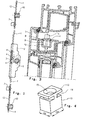
- The invention will be more readily understood on reading the following description with reference to the accompanying drawings, in which:
- Fig. 1
- shows a side view of a locking closure according to the invention,
- Fig. 2
- shows a front view of a locking closure according to the invention incorporated in a frame,
- Fig. 3
- shows a sectional view along the line III-III of Fig. 2, and
- Fig. 4
- shows a perspective view of a driving bar guide.
- A locking closure according to the invention consists of a
driving bar 1 which extends with a slip fit through a multi-part and take-apart casing 2 in which there is placed adriving gear wheel 3. The latter engages therespective cutouts 4 in thedriving bar 1. Saidcasing 2 with thedriving bar 1 is arranged in aframe 5 of a window and door wing, respectively, and in the area were a handle is placed for closing and opening, respectively, not shown in the Fig. For this purpose, saidgear wheel 3 is formed in its central part with a suitablemulti-sided hole 6 cooperating with said handle not shown. Longitudinally spaced from thecasing 2 there is a plurality oflocking members 7 arranged on thedriving bar 1, each saidlocking member 7 cooperates with a respective receiver (not shown) on the frame of a window and door, respectively. The number of saidlocking members 7 depends on the height of the window and door rabbet, respectively, so that said number consists of at least two locking members. - When completely assembled, the
driving bar 1 is arranged longitudinally movable with a slip fit in atransversal widening 8 of agroove 9 of the window anddoor frame 5, respectively. Typically, said widening 8 andgroove 9 are standardised and equal for all kinds of the respective closure, therefore they are not described in detail. A plurality ofguides 10 for thedriving bar 1 are placed in saidgroove 9, said guides being fixed in theframe 5 by means ofscrews 11 cooperating with the bottom of thegroove 9. With respect to thedriving bar 1 saidguides 10 are arranged in a manner that they are located, longitudinally to thedriving bar 1, at least one on the left side and/or one on the right side with regard to thelocking member 7. Thedriving bar 1 is formed in the area of eachguide 10 with an oblong through-hole 12 cooperating with saidguide 10. - According to the invention, said
guide 10 is formed as a cuboid, thelength 10a thereof equals approximately the width of thegroove 9 and is slightly bigger, respectively, and thelength 10b thereof equals approximately the width of the through-hole 12 in thedriving bar 1 and is slightly smaller, respectively. Theguide 10 is formed at the top end thereof with arectangular flange 13 extending only in the direction of thelength 10a of theguide 10. Acircular groove 14 is formed directly under saidflange 13 and is intended for cooperation with the oblong through-hole 12 in thedriving bar 1 and for that very reason the width thereof is slightly bigger than the width of thedriving bar 1. Furthermore, saidguide 10 comprises a through-hole 15 extending towards the free end thereof to receive saidscrew 11. - The
driving bar 1 and theguides 10 are assembled before inserting into theframe 5 of a window and door, respectively, i.e. in a manner that eachguide 10, with itsshorter side 10b, is positioned lengthwise with respect to the through-hole 12 and pushed through so as thedriving bar 1 is located with its thickness within the area of thecircular groove 14, and afterwards theguide 10 is turned about its vertical axis by 90 degrees in order that theflange 13 with its bottom surface rests on the upper surface of thedriving bar 1. The entire assembly of the driving bar 1and theguides 10 is then inserted in thegroove 9 and fixed by means of thescrews 11. Theguides 10 rest here on the bottom of thegroove 9 while thedriving bar 1 is sliding movably arranged in thecircular groove 14 of theguide 10 and in thegroove 8. Afterwards, the entire unit of thedriving bar 1 and theguides 10 is inserted in thegroove 9 and fixed by means of thescrews 11. Here, theguide 10 rests on the bottom of thegroove 9 while thedriving bar 1 is arranged in a sliding movable manner in thecircular groove 14 of theguide 10 and in thegroove 8. Saidguide 10 is formed in a manner that the bottom surface of thegroove 14 is aligned, when said guide is fixed in thegroove 9, with the bottom surface of thegroove 8.
Claims (7)
- A locking closure with a driving bar (1) for a window and door, respectively, that can be open and/or tilted, in particular the window and door, respectively, a frame (5) thereof is made of plastic or wood, said locking closure comprises the driving bar (1) with locking members (7) that is movable by means of a handle of the window and door, respectively, characterised in that with regard to each locking member (7) which is arranged on a driving bar (1) at a longitudinal distance from a casing (2) and in longitudinal direction on both sides with regard to said casing (2), said driving bar (1) is formed with a plurality of oblong through-holes (12) cooperating with a plurality of respective guides (10) fixed in a groove (9) in a frame (5) of a window and door, respectively.
- A locking closure according to claim 1, characterised in that said guide (10) is formed as a cuboid, the length (10a) thereof corresponds approximately to the width of the groove (9) and is slightly bigger, respectively, and the width (10b) thereof corresponds approximately to the width of the through-hole (12) in the driving bar (1) and is slightly smaller, respectively, said guide (10) is formed at the first end thereof with a flange (13) and a circular groove (14) is formed directly below said flange (13), said circular groove (14) being intended for cooperation with the oblong through-hole (12) in the driving bar (1), and that the guide (10) also comprises a through-hole (15) for the receiving of a fixing means (11).
- A locking closure according to any of the preceding claims, characterised in that with regard to the driving bar (1) said guides (10) are arranged in a manner that they are positioned in a longitudinal direction at least one on the left side and/or one on the right side with respect to each locking member (7).
- A locking closure according to any of the preceding claims, characterised in that said oblong through-holes (12) are arranged in the driving bar (1) in a longitudinal direction at least one on the left side and/or one on the right side of the each locking member (7).
- A locking closure according to any of the preceding claims, characterised in that the driving bar (1) is arranged with a slip fit in a transversal widening (8) of the groove (9).
- A locking closure according to any of the preceding claims, characterised in that the driving bar (1) is arranged with a slip fit in a circular groove (14) of the guide (10).
- A locking closure according to any of the preceding claims, characterised in that the guide (10) is arranged with a press fit in the groove (9) of the frame (5).
Priority Applications (3)
| Application Number | Priority Date | Filing Date | Title |
|---|---|---|---|
| AT05468011T ATE469282T1 (en) | 2005-06-03 | 2005-06-03 | CLOSURE WITH DRIVE ROD FOR WINDOWS AND/OR DOORS |
| DE602005021469T DE602005021469D1 (en) | 2005-06-03 | 2005-06-03 | Closure with drive rod for windows and / or doors |
| EP05468011A EP1728946B1 (en) | 2005-06-03 | 2005-06-03 | Locking closure with a driving bar for windows and/or doors |
Applications Claiming Priority (1)
| Application Number | Priority Date | Filing Date | Title |
|---|---|---|---|
| EP05468011A EP1728946B1 (en) | 2005-06-03 | 2005-06-03 | Locking closure with a driving bar for windows and/or doors |
Publications (2)
| Publication Number | Publication Date |
|---|---|
| EP1728946A1 true EP1728946A1 (en) | 2006-12-06 |
| EP1728946B1 EP1728946B1 (en) | 2010-05-26 |
Family
ID=35285308
Family Applications (1)
| Application Number | Title | Priority Date | Filing Date |
|---|---|---|---|
| EP05468011A Expired - Lifetime EP1728946B1 (en) | 2005-06-03 | 2005-06-03 | Locking closure with a driving bar for windows and/or doors |
Country Status (3)
| Country | Link |
|---|---|
| EP (1) | EP1728946B1 (en) |
| AT (1) | ATE469282T1 (en) |
| DE (1) | DE602005021469D1 (en) |
Cited By (2)
| Publication number | Priority date | Publication date | Assignee | Title |
|---|---|---|---|---|
| WO2008119460A1 (en) * | 2007-04-02 | 2008-10-09 | Roto Frank Ag | Drive rod arrangement comprising at least one drive rod and at least one drive rod guiding element |
| DE202014007618U1 (en) * | 2014-09-19 | 2016-01-14 | Gretsch-Unitas GmbH Baubeschläge | Profile arrangement for a door or window sash |
Citations (4)
| Publication number | Priority date | Publication date | Assignee | Title |
|---|---|---|---|---|
| DE2648315A1 (en) * | 1976-10-26 | 1978-04-27 | Ver Baubeschlag Gretsch Co | Cover housing for window actuating rods - is clamped without gaps with spacer for free movement of rods |
| EP0538562A1 (en) * | 1991-10-21 | 1993-04-28 | Siegenia-Frank Kg | Wing frame with drive-rod actuated fastening, for window, doors and the like |
| GB2304793A (en) * | 1995-09-25 | 1997-03-26 | Brunel Components Ltd | A slide for slidably attaching an espagnolette or locking bar to a window or door frame to facilitate positioning during mounting |
| DE10345758A1 (en) * | 2003-10-01 | 2005-04-21 | Wicona Bausysteme Gmbh | Method for fitting cover plate over control bar in door or window frame with fasteners set through slots in bar and secured without creating swarf |
-
2005
- 2005-06-03 AT AT05468011T patent/ATE469282T1/en not_active IP Right Cessation
- 2005-06-03 DE DE602005021469T patent/DE602005021469D1/en not_active Expired - Fee Related
- 2005-06-03 EP EP05468011A patent/EP1728946B1/en not_active Expired - Lifetime
Patent Citations (4)
| Publication number | Priority date | Publication date | Assignee | Title |
|---|---|---|---|---|
| DE2648315A1 (en) * | 1976-10-26 | 1978-04-27 | Ver Baubeschlag Gretsch Co | Cover housing for window actuating rods - is clamped without gaps with spacer for free movement of rods |
| EP0538562A1 (en) * | 1991-10-21 | 1993-04-28 | Siegenia-Frank Kg | Wing frame with drive-rod actuated fastening, for window, doors and the like |
| GB2304793A (en) * | 1995-09-25 | 1997-03-26 | Brunel Components Ltd | A slide for slidably attaching an espagnolette or locking bar to a window or door frame to facilitate positioning during mounting |
| DE10345758A1 (en) * | 2003-10-01 | 2005-04-21 | Wicona Bausysteme Gmbh | Method for fitting cover plate over control bar in door or window frame with fasteners set through slots in bar and secured without creating swarf |
Cited By (4)
| Publication number | Priority date | Publication date | Assignee | Title |
|---|---|---|---|---|
| WO2008119460A1 (en) * | 2007-04-02 | 2008-10-09 | Roto Frank Ag | Drive rod arrangement comprising at least one drive rod and at least one drive rod guiding element |
| DE102007017441B3 (en) * | 2007-04-02 | 2008-10-16 | Roto Frank Ag | Espagnolette with at least one drive rod and at least one drive rod guide element |
| EA014800B1 (en) * | 2007-04-02 | 2011-02-28 | Рото Франк Аг | Drive rod arrangement comprising at least one drive rod and at least one drive rod guiding element |
| DE202014007618U1 (en) * | 2014-09-19 | 2016-01-14 | Gretsch-Unitas GmbH Baubeschläge | Profile arrangement for a door or window sash |
Also Published As
| Publication number | Publication date |
|---|---|
| EP1728946B1 (en) | 2010-05-26 |
| ATE469282T1 (en) | 2010-06-15 |
| DE602005021469D1 (en) | 2010-07-08 |
Similar Documents
| Publication | Publication Date | Title |
|---|---|---|
| US11976508B2 (en) | Sliding door system, sliding door and buffer device | |
| DE112009000529T5 (en) | Lock with rotatable pawl | |
| GB2072740A (en) | Espagnolette fastening | |
| DE10034071B4 (en) | Device for closing an opening | |
| EP0276757B1 (en) | Torsion spring powered door | |
| EP2314810A2 (en) | Blocking device for an espagnolette rod | |
| EP3433461B1 (en) | Dispensing apparatus | |
| EP1520955B1 (en) | Clamping support for sun- or view-protecting device | |
| EP1728946B1 (en) | Locking closure with a driving bar for windows and/or doors | |
| EP2447452A1 (en) | Catch for a lock, assembly of a catch and lock and/or a closing element and a method for closing a closing element | |
| DE202007011076U1 (en) | Band arrangement with guide profile | |
| EP3702555B1 (en) | Door or window arrangement with a drive unit in the window frame | |
| KR101944017B1 (en) | A structure of a sliding door for bathroom cabinet | |
| CA2631282A1 (en) | Roller for sliding door | |
| EP0563550B2 (en) | Fitting for a door or window pivotable around its central axis | |
| DE602004004982T2 (en) | Corner guide for doors and windows | |
| BE1021702B1 (en) | WING OF A SLIDING WINDOW OR SLIDING DOOR AND SLIDING WINDOW OR SLIDING DOOR WITH SUCH A WING | |
| DE102005055384A1 (en) | Roller-shutter cabinet attachment device e.g. for window, has one face attached to shutter cabinet for moving roller-shutter cabinet and device is fixed in two different positions | |
| EP2104819B1 (en) | Refrigerator | |
| PL1469150T3 (en) | Espagnolette fitting and window, door, or similar with such an espagnolette fitting | |
| EP1754849B1 (en) | Device for mounting a door hinge on a door jamb | |
| EP3332915B1 (en) | Tool for mounting an operator for motorized swing doors and gates | |
| DE202005004128U1 (en) | Shutter for regulating a gas stream comprises lamellae with lids fitted to their ends having a projection coaxial to the bearing axis and facing away from the lamellae | |
| DE102007062276A1 (en) | Door drive and guide rail for a door drive | |
| EP2287434A2 (en) | Hermetic closure device for sliding doors and windows |
Legal Events
| Date | Code | Title | Description |
|---|---|---|---|
| PUAI | Public reference made under article 153(3) epc to a published international application that has entered the european phase |
Free format text: ORIGINAL CODE: 0009012 |
|
| AK | Designated contracting states |
Kind code of ref document: A1 Designated state(s): AT BE BG CH CY CZ DE DK EE ES FI FR GB GR HU IE IS IT LI LT LU MC NL PL PT RO SE SI SK TR |
|
| AX | Request for extension of the european patent |
Extension state: AL BA HR LV MK YU |
|
| 17P | Request for examination filed |
Effective date: 20070606 |
|
| AKX | Designation fees paid |
Designated state(s): AT BE BG CH CY CZ DE DK EE ES FI FR GB GR HU IE IS IT LI LT LU MC NL PL PT RO SE SI SK TR |
|
| AXX | Extension fees paid |
Extension state: HR Payment date: 20070606 Extension state: YU Payment date: 20070606 Extension state: BA Payment date: 20070606 |
|
| 17Q | First examination report despatched |
Effective date: 20071029 |
|
| GRAP | Despatch of communication of intention to grant a patent |
Free format text: ORIGINAL CODE: EPIDOSNIGR1 |
|
| GRAS | Grant fee paid |
Free format text: ORIGINAL CODE: EPIDOSNIGR3 |
|
| GRAA | (expected) grant |
Free format text: ORIGINAL CODE: 0009210 |
|
| AK | Designated contracting states |
Kind code of ref document: B1 Designated state(s): AT BE BG CH CY CZ DE DK EE ES FI FR GB GR HU IE IS IT LI LT LU MC NL PL PT RO SE SI SK TR |
|
| AX | Request for extension of the european patent |
Extension state: BA HR YU |
|
| REG | Reference to a national code |
Ref country code: GB Ref legal event code: FG4D |
|
| REG | Reference to a national code |
Ref country code: CH Ref legal event code: EP |
|
| REG | Reference to a national code |
Ref country code: IE Ref legal event code: FG4D |
|
| REF | Corresponds to: |
Ref document number: 602005021469 Country of ref document: DE Date of ref document: 20100708 Kind code of ref document: P |
|
| REG | Reference to a national code |
Ref country code: NL Ref legal event code: VDEP Effective date: 20100526 |
|
| LTIE | Lt: invalidation of european patent or patent extension |
Effective date: 20100526 |
|
| PG25 | Lapsed in a contracting state [announced via postgrant information from national office to epo] |
Ref country code: SE Free format text: LAPSE BECAUSE OF FAILURE TO SUBMIT A TRANSLATION OF THE DESCRIPTION OR TO PAY THE FEE WITHIN THE PRESCRIBED TIME-LIMIT Effective date: 20100526 Ref country code: LT Free format text: LAPSE BECAUSE OF FAILURE TO SUBMIT A TRANSLATION OF THE DESCRIPTION OR TO PAY THE FEE WITHIN THE PRESCRIBED TIME-LIMIT Effective date: 20100526 |
|
| PG25 | Lapsed in a contracting state [announced via postgrant information from national office to epo] |
Ref country code: SI Free format text: LAPSE BECAUSE OF FAILURE TO SUBMIT A TRANSLATION OF THE DESCRIPTION OR TO PAY THE FEE WITHIN THE PRESCRIBED TIME-LIMIT Effective date: 20100526 Ref country code: AT Free format text: LAPSE BECAUSE OF FAILURE TO SUBMIT A TRANSLATION OF THE DESCRIPTION OR TO PAY THE FEE WITHIN THE PRESCRIBED TIME-LIMIT Effective date: 20100526 Ref country code: FI Free format text: LAPSE BECAUSE OF FAILURE TO SUBMIT A TRANSLATION OF THE DESCRIPTION OR TO PAY THE FEE WITHIN THE PRESCRIBED TIME-LIMIT Effective date: 20100526 Ref country code: IS Free format text: LAPSE BECAUSE OF FAILURE TO SUBMIT A TRANSLATION OF THE DESCRIPTION OR TO PAY THE FEE WITHIN THE PRESCRIBED TIME-LIMIT Effective date: 20100926 |
|
| PG25 | Lapsed in a contracting state [announced via postgrant information from national office to epo] |
Ref country code: GR Free format text: LAPSE BECAUSE OF FAILURE TO SUBMIT A TRANSLATION OF THE DESCRIPTION OR TO PAY THE FEE WITHIN THE PRESCRIBED TIME-LIMIT Effective date: 20100827 Ref country code: CY Free format text: LAPSE BECAUSE OF FAILURE TO SUBMIT A TRANSLATION OF THE DESCRIPTION OR TO PAY THE FEE WITHIN THE PRESCRIBED TIME-LIMIT Effective date: 20100526 Ref country code: PL Free format text: LAPSE BECAUSE OF FAILURE TO SUBMIT A TRANSLATION OF THE DESCRIPTION OR TO PAY THE FEE WITHIN THE PRESCRIBED TIME-LIMIT Effective date: 20100526 |
|
| PG25 | Lapsed in a contracting state [announced via postgrant information from national office to epo] |
Ref country code: DK Free format text: LAPSE BECAUSE OF FAILURE TO SUBMIT A TRANSLATION OF THE DESCRIPTION OR TO PAY THE FEE WITHIN THE PRESCRIBED TIME-LIMIT Effective date: 20100526 Ref country code: PT Free format text: LAPSE BECAUSE OF FAILURE TO SUBMIT A TRANSLATION OF THE DESCRIPTION OR TO PAY THE FEE WITHIN THE PRESCRIBED TIME-LIMIT Effective date: 20100927 Ref country code: NL Free format text: LAPSE BECAUSE OF FAILURE TO SUBMIT A TRANSLATION OF THE DESCRIPTION OR TO PAY THE FEE WITHIN THE PRESCRIBED TIME-LIMIT Effective date: 20100526 Ref country code: MC Free format text: LAPSE BECAUSE OF NON-PAYMENT OF DUE FEES Effective date: 20100630 Ref country code: EE Free format text: LAPSE BECAUSE OF FAILURE TO SUBMIT A TRANSLATION OF THE DESCRIPTION OR TO PAY THE FEE WITHIN THE PRESCRIBED TIME-LIMIT Effective date: 20100526 |
|
| REG | Reference to a national code |
Ref country code: CH Ref legal event code: PL |
|
| PG25 | Lapsed in a contracting state [announced via postgrant information from national office to epo] |
Ref country code: BE Free format text: LAPSE BECAUSE OF FAILURE TO SUBMIT A TRANSLATION OF THE DESCRIPTION OR TO PAY THE FEE WITHIN THE PRESCRIBED TIME-LIMIT Effective date: 20100526 Ref country code: CZ Free format text: LAPSE BECAUSE OF FAILURE TO SUBMIT A TRANSLATION OF THE DESCRIPTION OR TO PAY THE FEE WITHIN THE PRESCRIBED TIME-LIMIT Effective date: 20100526 Ref country code: SK Free format text: LAPSE BECAUSE OF FAILURE TO SUBMIT A TRANSLATION OF THE DESCRIPTION OR TO PAY THE FEE WITHIN THE PRESCRIBED TIME-LIMIT Effective date: 20100526 Ref country code: RO Free format text: LAPSE BECAUSE OF FAILURE TO SUBMIT A TRANSLATION OF THE DESCRIPTION OR TO PAY THE FEE WITHIN THE PRESCRIBED TIME-LIMIT Effective date: 20100526 |
|
| PG25 | Lapsed in a contracting state [announced via postgrant information from national office to epo] |
Ref country code: IT Free format text: LAPSE BECAUSE OF FAILURE TO SUBMIT A TRANSLATION OF THE DESCRIPTION OR TO PAY THE FEE WITHIN THE PRESCRIBED TIME-LIMIT Effective date: 20100526 |
|
| PLBE | No opposition filed within time limit |
Free format text: ORIGINAL CODE: 0009261 |
|
| STAA | Information on the status of an ep patent application or granted ep patent |
Free format text: STATUS: NO OPPOSITION FILED WITHIN TIME LIMIT |
|
| GBPC | Gb: european patent ceased through non-payment of renewal fee |
Effective date: 20100826 |
|
| PG25 | Lapsed in a contracting state [announced via postgrant information from national office to epo] |
Ref country code: CH Free format text: LAPSE BECAUSE OF NON-PAYMENT OF DUE FEES Effective date: 20100630 Ref country code: DE Free format text: LAPSE BECAUSE OF NON-PAYMENT OF DUE FEES Effective date: 20110101 Ref country code: IE Free format text: LAPSE BECAUSE OF NON-PAYMENT OF DUE FEES Effective date: 20100603 Ref country code: LI Free format text: LAPSE BECAUSE OF NON-PAYMENT OF DUE FEES Effective date: 20100630 |
|
| 26N | No opposition filed |
Effective date: 20110301 |
|
| REG | Reference to a national code |
Ref country code: FR Ref legal event code: ST Effective date: 20110228 |
|
| PG25 | Lapsed in a contracting state [announced via postgrant information from national office to epo] |
Ref country code: FR Free format text: LAPSE BECAUSE OF NON-PAYMENT OF DUE FEES Effective date: 20100726 |
|
| PG25 | Lapsed in a contracting state [announced via postgrant information from national office to epo] |
Ref country code: GB Free format text: LAPSE BECAUSE OF NON-PAYMENT OF DUE FEES Effective date: 20100826 |
|
| PG25 | Lapsed in a contracting state [announced via postgrant information from national office to epo] |
Ref country code: HU Free format text: LAPSE BECAUSE OF FAILURE TO SUBMIT A TRANSLATION OF THE DESCRIPTION OR TO PAY THE FEE WITHIN THE PRESCRIBED TIME-LIMIT Effective date: 20101127 Ref country code: LU Free format text: LAPSE BECAUSE OF NON-PAYMENT OF DUE FEES Effective date: 20100603 Ref country code: BG Free format text: LAPSE BECAUSE OF FAILURE TO SUBMIT A TRANSLATION OF THE DESCRIPTION OR TO PAY THE FEE WITHIN THE PRESCRIBED TIME-LIMIT Effective date: 20100526 |
|
| PG25 | Lapsed in a contracting state [announced via postgrant information from national office to epo] |
Ref country code: TR Free format text: LAPSE BECAUSE OF FAILURE TO SUBMIT A TRANSLATION OF THE DESCRIPTION OR TO PAY THE FEE WITHIN THE PRESCRIBED TIME-LIMIT Effective date: 20100526 |
|
| PG25 | Lapsed in a contracting state [announced via postgrant information from national office to epo] |
Ref country code: BG Free format text: LAPSE BECAUSE OF FAILURE TO SUBMIT A TRANSLATION OF THE DESCRIPTION OR TO PAY THE FEE WITHIN THE PRESCRIBED TIME-LIMIT Effective date: 20100826 |
|
| PG25 | Lapsed in a contracting state [announced via postgrant information from national office to epo] |
Ref country code: ES Free format text: LAPSE BECAUSE OF FAILURE TO SUBMIT A TRANSLATION OF THE DESCRIPTION OR TO PAY THE FEE WITHIN THE PRESCRIBED TIME-LIMIT Effective date: 20100906 |