EP2128751A1 - Appareil de traitement d'informations, programme de traitement d'informations et procédé de traitement d'informations - Google Patents
Appareil de traitement d'informations, programme de traitement d'informations et procédé de traitement d'informations Download PDFInfo
- Publication number
- EP2128751A1 EP2128751A1 EP07738802A EP07738802A EP2128751A1 EP 2128751 A1 EP2128751 A1 EP 2128751A1 EP 07738802 A EP07738802 A EP 07738802A EP 07738802 A EP07738802 A EP 07738802A EP 2128751 A1 EP2128751 A1 EP 2128751A1
- Authority
- EP
- European Patent Office
- Prior art keywords
- person
- positional relation
- display
- display device
- information
- Prior art date
- Legal status (The legal status is an assumption and is not a legal conclusion. Google has not performed a legal analysis and makes no representation as to the accuracy of the status listed.)
- Withdrawn
Links
- 230000010365 information processing Effects 0.000 title claims abstract description 43
- 238000003672 processing method Methods 0.000 title claims description 5
- 238000000034 method Methods 0.000 claims description 97
- 238000001514 detection method Methods 0.000 claims description 38
- 230000007423 decrease Effects 0.000 claims description 14
- 238000010586 diagram Methods 0.000 description 29
- 230000003247 decreasing effect Effects 0.000 description 8
- 238000013459 approach Methods 0.000 description 6
- 230000000694 effects Effects 0.000 description 4
- 239000004973 liquid crystal related substance Substances 0.000 description 3
- 230000033001 locomotion Effects 0.000 description 3
- 238000005259 measurement Methods 0.000 description 2
- 238000012544 monitoring process Methods 0.000 description 2
- 238000002360 preparation method Methods 0.000 description 2
- 210000003462 vein Anatomy 0.000 description 2
- 238000004458 analytical method Methods 0.000 description 1
- 230000005540 biological transmission Effects 0.000 description 1
- 238000004891 communication Methods 0.000 description 1
- 238000004590 computer program Methods 0.000 description 1
- 239000000284 extract Substances 0.000 description 1
- 238000009434 installation Methods 0.000 description 1
- 238000012886 linear function Methods 0.000 description 1
- 239000000725 suspension Substances 0.000 description 1
- 230000000007 visual effect Effects 0.000 description 1
Images


Classifications
-
- G—PHYSICS
- G08—SIGNALLING
- G08B—SIGNALLING OR CALLING SYSTEMS; ORDER TELEGRAPHS; ALARM SYSTEMS
- G08B13/00—Burglar, theft or intruder alarms
- G08B13/18—Actuation by interference with heat, light, or radiation of shorter wavelength; Actuation by intruding sources of heat, light, or radiation of shorter wavelength
- G08B13/189—Actuation by interference with heat, light, or radiation of shorter wavelength; Actuation by intruding sources of heat, light, or radiation of shorter wavelength using passive radiation detection systems
- G08B13/194—Actuation by interference with heat, light, or radiation of shorter wavelength; Actuation by intruding sources of heat, light, or radiation of shorter wavelength using passive radiation detection systems using image scanning and comparing systems
- G08B13/196—Actuation by interference with heat, light, or radiation of shorter wavelength; Actuation by intruding sources of heat, light, or radiation of shorter wavelength using passive radiation detection systems using image scanning and comparing systems using television cameras
-
- G—PHYSICS
- G06—COMPUTING; CALCULATING OR COUNTING
- G06F—ELECTRIC DIGITAL DATA PROCESSING
- G06F21/00—Security arrangements for protecting computers, components thereof, programs or data against unauthorised activity
- G06F21/30—Authentication, i.e. establishing the identity or authorisation of security principals
- G06F21/31—User authentication
- G06F21/34—User authentication involving the use of external additional devices, e.g. dongles or smart cards
- G06F21/35—User authentication involving the use of external additional devices, e.g. dongles or smart cards communicating wirelessly
-
- G—PHYSICS
- G06—COMPUTING; CALCULATING OR COUNTING
- G06F—ELECTRIC DIGITAL DATA PROCESSING
- G06F21/00—Security arrangements for protecting computers, components thereof, programs or data against unauthorised activity
- G06F21/70—Protecting specific internal or peripheral components, in which the protection of a component leads to protection of the entire computer
- G06F21/82—Protecting input, output or interconnection devices
- G06F21/84—Protecting input, output or interconnection devices output devices, e.g. displays or monitors
-
- G—PHYSICS
- G06—COMPUTING; CALCULATING OR COUNTING
- G06Q—INFORMATION AND COMMUNICATION TECHNOLOGY [ICT] SPECIALLY ADAPTED FOR ADMINISTRATIVE, COMMERCIAL, FINANCIAL, MANAGERIAL OR SUPERVISORY PURPOSES; SYSTEMS OR METHODS SPECIALLY ADAPTED FOR ADMINISTRATIVE, COMMERCIAL, FINANCIAL, MANAGERIAL OR SUPERVISORY PURPOSES, NOT OTHERWISE PROVIDED FOR
- G06Q50/00—Information and communication technology [ICT] specially adapted for implementation of business processes of specific business sectors, e.g. utilities or tourism
- G06Q50/10—Services
-
- G—PHYSICS
- G06—COMPUTING; CALCULATING OR COUNTING
- G06F—ELECTRIC DIGITAL DATA PROCESSING
- G06F2221/00—Indexing scheme relating to security arrangements for protecting computers, components thereof, programs or data against unauthorised activity
- G06F2221/21—Indexing scheme relating to G06F21/00 and subgroups addressing additional information or applications relating to security arrangements for protecting computers, components thereof, programs or data against unauthorised activity
- G06F2221/2111—Location-sensitive, e.g. geographical location, GPS
Definitions
- the present invention relates to an information processing apparatus, an information processing program, and an information processing method that control a display device capable of displaying information.
- An widely-used terminal such as PC (Personal Computer) that provides services includes a function to authenticate a user using a password, a fingerprint, an iris, a vein, or the like, in order to allow only an authorized user to use services.
- PC Personal Computer
- Patent Document 1 there is a technique that prevents an unauthorized person behind or next to the user from watching information displayed on a monitor when there is a plurality of people around the terminal that provides services (see Patent Document 1, for example).
- a person in an area where the services are available is detected by a camera, RFID (Radio Frequency Identification), or the like.
- RFID Radio Frequency Identification
- each person is identified by face authentication, or the like. If there is any person other than those who are allowed to access, control processes such as suspending or halting the services are carried out to increase the level of security.
- a liquid-crystal shutter is installed on the front of a liquid crystal display.
- a different image is provided. Therefore, information is displayed only toward the authorized user, thereby preventing information from leaking to those who do not have the right of access.
- Non-Patent Document 4 there is a technique that detects an object on an image taken by a camera (see Patent Document 4, for example). Moreover, there is a technique that extracts a pedestrian using a laser scanner (Non-Patent Document 1, for example). Moreover, there is a technique that tracks the position of a moving object using a back projection method and Kalman filter (see Non-Patent Document 2, for example). Moreover, there is a standard for the estimation of minimum legible size for characters(see Non-Patent Document 3, for example.
- the present invention has been made to solve the above problems.
- the object of the present invention is to provide an information processing apparatus, an information processing program, and an information processing method that prevent the information displayed on the display device from leaking.
- an information processing program that causes a computer to perform a process of controlling a display device capable of displaying information, includes: a positional relation acquisition step that detects a person who is in a predetermined area around the display device and acquires a positional relation between the person and the display device; and a control step that stores a correspondence between the positional relation and the state of displaying on the display device and controls the state of displaying on the display device based on the correspondence and the positional relation acquired by the positional relation acquisition section.
- an information processing method that controls a display device capable of displaying information includes: a positional relation acquisition step that detects a person who is in a predetermined area around the display device and acquires a positional relation between the person and the display device; and a control step that stores a correspondence between the positional relation and the state of displaying on the display device and controls the state of displaying on the display device based on the correspondence and the positional relation acquired by the positional relation acquisition section.
- the information display system includes an authentication device.
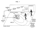
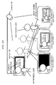
- FIG. 1 is a block diagram showing an example of the configuration of the information display system according to the present embodiment.
- the information display system includes a server (information processing apparatus) 101, an access terminal (display device) 102, one or a plurality of cameras 103, and an authentication device 104.
- the access terminal 102 displays characters, images, sounds or the like according to user operation.
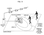
- An area A is an area where an intruder can look at the information displayed on the access terminal 102, or an area where the intruder can operate the access terminal 102.
- An area B exists outside the area A. The size of the area B is determined so as to allow a user of the access terminal 102 to complete a process for preventing information from leaking, such as suspending work, until the intruder enters the area A after entering the area B.
- the camera 103 takes pictures of a work space (a predetermined area) including the access terminal 102, and continuously outputs a plurality of images.
- the work space is, for example, an entire room where the access terminal 102 is placed.
- the authentication device 104 is placed in the work space, for example, at the entrance to the work-space room.
- the authentication device 104 authenticates who a person who has performed an authentication operation is by carrying out, for example, biometric authentication such as fingerprint recognition. Incidentally, there may not be the authentication device 104 besides the camera 103.
- the camera 103 may take a picture of the face of the person, with the server 101 carrying out face authentication to authenticate the person.
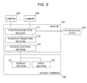
- FIG. 2 is a block diagram illustrating an example of the configuration of the server and the access terminal, according to the present embodiment.
- the server 101 includes a position detection section 111, a position prediction section 112, and an access control section 113.
- the access terminal 102 has a display section 121 including a monitor and a speaker, and an input section 122 including a keyboard and a mouse.
- the position detection section 111 detects a person who has entered the work space using an image taken by the camera.
- the position detection section 111 detects the person from the image using the technique of Patent Document 3.
- the positions of places shown in the image are associated with the positions of places within the work space in advance. Therefore, the position detection section 111 detects the position of the person in the work space.
- the position detection section 111 regards the person the position detection section 111 has detected at the time of the identification process at the place where the authentication device 104 is placed as an authenticated person, and records the authenticated person. Moreover, the position detection section 111 records a person who was not identified by the authentication device 104 or a person who has not performed the authentication operation as an unauthenticated person. The position detection section 111 allocates already-registered IDs to the authenticated persons, and other IDs that are different from each other to the unauthenticated persons.
- the position prediction section 112 manages a position management table, a prediction time management table, an ID access right management table, a type-of-work access right management table, and an area management table.
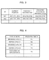
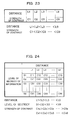
- FIG. 3 shows a table as an example of the position management table according to the present embodiment.
- the position prediction section 112 acquires the position and ID of the person detected by the position detection section 111, and uses the position management table to manage, on a per person basis, IDs; current positions of the persons; positions where the persons were a predetermined period of time (T seconds) ago; and predicted positions where the persons might be after a prediction time (N seconds) has passed.
- the position detection section 111 associates the current image of the whole body or part of the body of the person with the past image.
- the position detection section 111 records the history of the persons' positions.
- the positions where the persons were T seconds ago, and the current positions are recorded.
- the position detection section 111 uses, for example, the normalized correlation of gray values between the two images, and associates portions that have the highest correlation values as the same portion (person).
- FIG. 4 shows a table as an example of the prediction time management table according to the present embodiment.
- the prediction time is set for each expected type of work (each type of display information), and stored in the prediction time management table in advance.
- the position prediction section 112 acquires from the access control section 113 the current type of work the user of the access terminal 102 is engaged in, and determines the prediction time based on the type of work and the prediction time management table.
- the position prediction section 112 predicts the position where the person might be N seconds later, based on the current position and the position where the person was T seconds ago that are stored in the above position management table.
- the position detection section 111 may record more past positions, with the position prediction section 112 predicting the position where the person might be N seconds later from the recorded past positions.
- the position prediction section 112 for example, approximates the relation between the time and position of the person from past to present by a linear function.
- the position prediction section 112 uses the function to predict the position where the person might be a predetermined period of time later, and regards the position as the predicted position.
- the position prediction section 112 may turn the movement of the person into a model, and predict the position based on the model. For example, the position prediction section 112 turns the movement of the person into a model by uniform motion, and uses Kalman filter to predict the position where the person might be N seconds later.
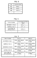
- FIG. 5 shows a table as an example of the ID access right management table according to the present embodiment.
- the access right (level) is set for each registered ID, and stored in the ID access right management table in advance.
- FIG. 6 shows a table as an example of the type-of-work access right management table according to the present embodiment.
- a necessary access right (level) is set for each expected type of work, and stored in the type-of-work access right management table in advance. Based on the current type of work the user of the access terminal 102 is engaged in and the type-of-work access right management table, the position prediction section 112 determines the access right necessary for the type of work.
- the position prediction section 112 determines the access right of the person. Moreover, the position prediction section 112 compares the access right necessary for the type of work, which was determined as described above, with the access right of the person. If the level of the person's access right is lower than the level of the access right necessary for the type of work, or if the person is not authenticated, the position prediction section 112 determines that the person is an intruder. Incidentally, regardless of type of work, the level of the necessary access right may be fixed to omit the type-of-work access right management table.
- the position prediction section 112 changes the prediction time, the size of the area A, and the size of the area B depending on type of work (the degree of secrecy of the information output by the access terminal 102).
- the type of work for example, includes the type or number of running applications, the amount of time passed since the start of work, and the amount of data changed or added after the start of work.
- FIG. 7 shows a table as an example of the area management table according to the present embodiment.
- the radius of the area A, and the radius of the area B are set for each expected type of work, and stored in the area management table in advance.
- the prediction time, the size of the area A, and the size of the area B may be predetermined as fixed values by taking into account the time necessary for carrying out operations to prevent leakage of information, such as the time necessary for the user to suspend work after an alarm is raised.
- the position prediction section 112 may change the values in accordance with the type of work at the time when the alarm was raised.
- the operations necessary for preventing leakage of information includes saving work, and closing a window.
- the position prediction section 112 raises an alarm to the access terminal 102. Moreover, the predicted position of the intruder predicted by the position prediction section 112 is within the area A, the position prediction section 112 instructs the access terminal 102 to stop work.
- the access terminal 102 uses, through the display device 121, characters, images, sounds, vibration or the like to inform the user that the intruder approaches.
- the access terminal 102 stops output from the display section 121, and suspends input from the input section 122.
- the access terminal 102 may ask the user whether it is possible to suspend access.
- the access terminal 102 does not suspend access, records the fact that the access terminal 102 has continued access in accordance with the user's decision, and, at the same time, saves the image of the work space taken by the camera in order to record the situation at that time.
- the image may be used for analysis or the like to identify a person who does not have the right of access.
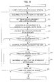
- FIG. 8 is a flowchart illustrating an example of the operation of the information display system according to the present embodiment.
- the user starts using the access terminal 102 (S11).
- the position prediction section 112 acquires from the access control section 113 the current type of work the user is engaged in (S12).
- the position prediction section 112 determines the size of the area A and the size of the area B based on the type of work the user is engaged in and the area management table, and determines the prediction time based on the type of work and the prediction time management table (S13).
- the position prediction section 112 acquires the access right of the person who is in the work space using the ID access right management table (S14).
- the position prediction section 112 regards a person who does not have the access right as an intruder, and calculates the predicted position (positional relation), or the position where the intruder might be after the prediction time has passed (S15).
- the position prediction section 112 makes a determination as to whether the predicted position is within the area A (whether the distance between the access terminal 102 and the predicted position is less than or equal to the radius of the area A) (S21). If the predicted position is not within the area A (S21, N), the position prediction section 112 proceeds to a process of S23. If the predicted position is within the area A (S21, Y), the access control section 113 instructs the access terminal 102 to stop work. The instructed access terminal 102 suspends the work (access) the user is engaged in (correspondence)(S22), and proceeds to a process of S25.
- the access terminal 102 instructed by the access control section 113 to suspend work carries out processes, such as suspending output from the display section 121 and suspending input from the input section 122.
- the access terminal 102 may ask the user whether it is possible to suspend access. In this case, if the user chooses not to suspend access, the access terminal 102 will not suspend access even when a target intruder approaches; the access control section 113 records the fact that the access terminal 102 has continued access in accordance with the user's decision, and, at the same time, saves the image of the work space taken by the camera in order to record the situation at that time.
- the position prediction section 112 makes a determination as to whether the predicted position is within the area B (whether the distance between the access terminal 102 and the predicted position is less than or equal to the radius of the area B) (S23). If the predicted position is not within the area B (S23, N), the position prediction section 112 proceeds to a process of S25. If the predicted position is within the area B (S23, Y), the access control section 113 raises an alarm to the access control terminal 102 (correspondence). An output section 131 of the access terminal 102 that received the alarm informs the user that the intruder is approaching (S24), and proceeds to the process of S25.
- the display section 121 uses characters, images, voice, sound, vibration or the like to inform the user that the person who does not have the access right is approaching.
- the access control section 113 makes a determination as to whether the user has stopped using the access terminal 102 (S25). If the user has not stopped using the access terminal 102 (S25, N), the access control section 113 returns to the process of S12. If the user has stopped using the access terminal 102 (S25, Y), the flow ends.
- the position prediction section 112 checks whether the prediction position is within the area A where access should be suspended. However, depending on the work space or the installation condition of the authentication device, the position prediction section 112 may start checking from the area B where the informing process should be carried out.
- the position of the person who does not have the access right or unauthorized user is tracked, and the position is predicted. Therefore, work can be suspended until the person is allowed to access the access terminal 102, thereby reducing the risk that information will be leaked by a peeper or the like. Moreover, before the person is allowed to access the access terminal 102, the user is notified of the possibility that information might be leaked. Therefore, the user is given enough time to make appropriate preparation. In this manner, convenience is improved.
- the information display system does not require the authentication device.
- FIG. 9 is a block diagram illustrating an example of the configuration of the information display system according to the present embodiment.
- the same reference symbols as those of FIG. 1 represent the same, or equivalent, objects as those of FIG. 1 , and the description, therefore, will be omitted here.
- the system shown in the diagram includes a server 201 instead of the server 101, and does not require the authentication device 104.
- FIG. 10 is a block diagram illustrating an example of the configuration of a server and an access terminal according to the present embodiment.
- the same reference symbols as those of FIG. 2 represent the same, or equivalent, objects as those of FIG. 2 , and the description, therefore, will be omitted here.
- the server 201 includes a position detection section 211 instead of the position detection section 111, and a position prediction section 212 instead of the position prediction section 112.
- the position detection section 211 detects the person who enters the work space using the image taken by the camera 103. Moreover, the positions of places shown in the image are associated with the positions of places within the work space in advance. Therefore, the position detection section 211 detects the position of the person in the work space. Moreover, the position detection section 211 detects the user of the access terminal 102 from the position where the access terminal 102 has been placed in advance. The position detection section 211 regards any people other than the user, whom the position detection section 211 has detected, as intruders, and allocates different IDs to the intruders.
- the position prediction section 212 calculates the predicted position where the intruder might be, and, based on the predicted position, the type of work, and the area management table, makes a determination as to warning and suspension. According to the present embodiment, since any detected people other than the user are regarded as intruders, the ID access right management table and the type-of-work access right management table are unnecessary.
- the position prediction section 212 calculates the predicted positions of all the intruders, and makes a determination as to whether the intruders have entered the area A and the area B based on the predicted positions of all the intruders. Subsequently, in a similar manner to that of Embodiment 1, the access control section 113 suspends work or raises an alarm based on the result of determination.
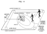
- a laser scanner may be used to detect the position of the person.
- FIG. 11 is a block diagram illustrating an example of another configuration of the information display system according to the present embodiment.
- the same reference symbols as those of FIG. 9 represent the same, or equivalent, objects as those of FIG. 9 , and the description, therefore, will be omitted here.
- the system shown in the diagram includes one or a plurality of laser scanners 105 instead of the camera 103.
- the laser scanner 105 measures the work space containing the access terminal 102.
- the position detection section 211 detects a person heading to the work space from the measurement data of the laser scanner 105.
- the position detection section 211 detects the position of the person from the measurement data of the laser scanner 105 using the technique of Non-Patent Document 1.
- authentication is unnecessary for the person who has entered the work space.
- the information display system controls the size of displayed information (displaying state) in accordance with the position of an unauthorized user (positional relation).
- FIG. 12 is a block diagram illustrating an example of the configuration of the information display system according to the present embodiment.
- the information display system includes a computer (information processing apparatus) 301 such as PC.
- the following components are connected to the computer 301: a display (display device) 302 that displays information supplied from the computer 301, a keyboard 303 and mouse 304 that input various data into the computer 301, an authentication device 305 that carries out authentication, and a camera 306 that recognizes the position of a person around the computer 301.
- the camera 306 is placed so as to take pictures of the area around the computer 301.
- a laser sensor, a RFID leader, or the like can be substituted for the camera 306 as long as the position of the person can be detected.
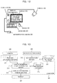
- FIG. 13 is a block diagram illustrating an example of the configuration of a computer according to the present embodiment.
- the computer 301 includes an authentication information database 321, and a display information database 322.
- User information such as IDs, names, authentication information, the rights to browse information, is registered in the authentication information database 321.
- the user information is used to perform a user authentication process.
- the display information database 322 for each piece of display information which will be browsed on the display 302, a file name, the access right which is necessary to browse the piece of display information, and the level of secrecy for the piece of display information, and the like are registered.
- the computer 301 includes a position detection section 311, which detects a person from the image taken by the camera 306 and tracks the position of the person; an authentication section 312, which performs authentication based on the authentication information database 321; a display information change determination section 313, which makes a determination as to whether to change the display information in accordance with the position of the person detected by the position detection section 311 and the result of authentication by the authentication section 312; and a display information change section 314, which changes the display information and displays the display information on the display 302.
- the following describes a detection process performed by the computer 301.
- FIG. 14 is a flowchart illustrating an example of the detection process performed by the computer, according to the present embodiment.
- the position detection section 311 detects the position of the person who is in a monitoring area (work space) around the display 302 from the image taken by the camera 306 (S31).
- the methods to recognize the position of the person using a plurality of cameras includes the method that uses the back projection method and Kalman filter as described in Non-Patent Document 2.
- the method that users a laser beam includes the one that uses a multi-laser scanner to measure the foot of a person as described in Non-Patent Document 1.
- the authentication section 312 performs authentication using the authentication device 305 at such times as when a person browsing the display information or a person around the display 302 logs into the computer 301 and when the person enters a room where the display 302 is placed.
- the authentication section 312 then makes a determination as to whether the person is authenticated (S32). Specifically, using the authentication device 305 that uses biometric authentication such as vein or fingerprint, the authentication section 312 carries out a checkup on the authentication information database 321 in order to identify the person, and then outputs personal information about the person.
- the following method is also available:
- the authentication section 312 displays a dialog box for authenticating a user on the display 302, and authentication is carried out with a user ID and password. In this case, the authentication device 305 is unnecessary.
- the display information change determination section 313 acquires the access right of the person authenticated by the authentication section 312 (S33), and associates the access right with the position of the person based on the position of the place where authentication was carried out by the authentication section 312 (where the authentication device 305 is placed), the position of the person detected by the position detection section 311 at the time of authentication, and the access right of the person authenticated by the authentication section 312 (S35). Then, the flow comes to an end.
- the display information change determination section 313 sets a person who failed to be authenticated as a person who does not have the right of access to the display information, and associates the position of the person detected by the position detection section 311 with the access right (S35). Then, the flow comes to an end.
- the following describes a display process performed by the computer 301.
- FIG. 15 is a flowchart illustrating an example of the display process performed by the computer, according to the present embodiment.
- the position detection section 311 detects the position of person within the monitoring area (work space) around the display 302 from the image taken by the camera 306 (S40).
- the display information change determination section 313 makes a determination as to whether a person (unauthorized user) who does not have the right of access to the display information is at a position where the person can look at the display information (S41).
- the display information change section 314 acquires the display information in accordance with the operation of the browsing person who operates the keyboard 303 and the mouse 304 (S42), and displays the display information on the display 302 (S44). Then, the flow comes to an end. At this time, if the person who tries to display the display information does not have the right to browse the display information, the display 302 does not display the display information.
- the display information change section 314 calculates the distance between the unauthorized user and the display 302 based on the position of the unauthorized user and the position of the place where the display 302 is placed in advance, carries out a display information change process to change the display information in accordance with the distance (S43), and displays the display information processed by the display information change process on the display 302 (S44). Then, the flow comes to an end.
- the display process is repeated while the browsing person is browsing the display information. Moreover, if it is detected that the unauthorized user has moved away to a place where the unauthorized user cannot watch the display device 302, the display information change section 314 replaces the display information changed by the display information change process with the original display information.
- FIG. 16 is a conceptual diagram illustrating an example of the display information change process according to the present embodiment.
- X, Y, and Z individually represent the position of the unauthorized user. Moreover, the diagram shows the piece of display information seen from X, the piece of display information seen from Y, and the piece of display information seen from Z, so as to make the pieces correspond to the positions. If the unauthorized user moves from X to Y to watch the display information, the distance from the unauthorized user to the display 302 becomes short. However, the size of the display information becomes small. Therefore, the unauthorized user cannot recognize the display information. Similarly, if the unauthorized user moves from Y to Z, the distance from the unauthorized user to the display 302 becomes shorter. However, the size of the display information becomes smaller. Therefore, the unauthorized user cannot recognize the display information.
- the display information change section 314 changes the size of the display information (characters and images) in a way that allows the authorized user to see the display information but does not allow the unauthorized user, before displaying the display information on the display 302. That is, as the unauthorized user approaches the display 302, the size of the display information displayed on the display 302 becomes small. Therefore, the unauthorized user cannot recognize the display information.
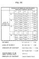
- FIG. 17 shows a table as a first example of the display character size selection table according to the present embodiment.
- the relation is set in the following manner: as the distance (L1, L2, ...) between the unauthorized user and the display 302 becomes shorter, the size of characters of the display information (F1, F2, ...) becomes smaller.
- the character size is represented by point or the ratio of the displayed character size to a standard size.
- the relation between the distance and the size of the displayed characters is determined based on a criterion like the one disclosed in Non-Patent Document 3.
- the display information change section 314 determines the size of the displayed characters based on the unauthorized-user distance and the display character size selection table, thereby changing the size of characters displayed on the display 302.
- the size of images and windows may be similarly changed to decrease the likelihood that the unauthorized user would recognize the display information.
- FIG. 18 shows a table as a second example of the display character size selection table according to the present embodiment.
- the level of secrecy (the level of a necessary access right) is preset for each piece of the display information.
- the display character size selection table of this case as the level of secrecy of the display information (S1, S2, ...) rises, the size of characters of the display information (F11, F21, 7) becomes small.
- the size of characters of the display information (F11, F12, %) becomes small. Therefore, as the level of secrecy rises, the likelihood that the unauthorized user would see the display information is decreased.
- FIG. 19 shows a table as a third example of the display character size selection table according to the present embodiment.
- the display character size selection table of this case as well as the effect of the second example of the display character size selection table, the following effect can be obtained: As the level of the access right (a, b, %) of the unauthorized user approaching the display 302 declines with respect to the level of secrecy of the display information (S1, S2, 7), the size of characters of the display information (F11-a, F11-b, %) becomes smaller. Therefore, the likelihood that the person who does not have the right of access to the display information would see the display information is decreased.
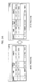
- FIG. 20 shows screens as a first example of the display information change process according to the present embodiment.
- the screen on the left shows the display information before the display information change process.
- the screen on the right shows the display information after the display information change process.
- the display information change process makes the character size of the whole piece of the display information small in accordance with the distance.
- FIG. 21 shows a screen as the second example of the display information change process according to the present embodiment.
- the screen on the left shows the display information before the display information change process.
- the screen on the right shows the display information after the display information change process.
- the character size of a predetermined item such as an item for personal information the leakage of which is not allowed, is made small.
- a different level of secrecy may be preset for each item including name, address, and phone number.
- the degree of change in the size of the display information may vary according to item.
- the information display system controls the contrast of the display information (displaying state) according to where the unauthorized user is.
- the configuration of the display information system and the computer is the same as that of Embodiment 3.
- the detection process and the display process are the same as those of Embodiment 3, but only the display information change process is different.
- FIG. 22 is a conceptual diagram illustrating an example of the display information change process according to the present embodiment.
- X, Y, and Z individually represent the positions of the unauthorized user. Moreover, the diagram shows the piece of display information seen from X, the piece of display information seen from Y, and the piece of display information seen from Z, so as to make the pieces correspond to the positions. If the unauthorized user moves from X to Y to watch the display information, the distance from the unauthorized user to the display 302 becomes short. However, the contrast of the display information decreases. Therefore, the unauthorized user cannot recognize the display information. Similarly, the unauthorized user moves from Y to Z, the distance from the unauthorized user to the display 302 becomes shorter. However, the contrast of the display information declines further. Therefore, the unauthorized user cannot recognize the display information.
- the display information change section 314 changes, as illustrated in the diagram, the contrast of the display information (characters and images) in a way that allows the authorized user to see the display information but does not allow the unauthorized user, before displaying the display information on the display 302. That is, as the unauthorized user approaches the display 302, the contrast of the display information displayed on the display 302 decreases. Therefore, the unauthorized user cannot recognize the display information.
- FIG. 23 shows a table as a first example of the display contrast strength selection table according to the present embodiment.
- the relation is set in the following manner: as the distance (L1, L2, ...) between the unauthorized user and the display 302 becomes shorter, the contrast of the display information (Strength of contrast: C1, C2, ...) decreases.
- the contrast is represented by a gradation number or the ratio of the displayed information's contrast to a standard contrast.
- the display information change section 314 may perform such processes as lowering the brightness of the display information, changing a combination of the characters' color and the background color so as to make the characters and the background less noticeable, or applying stronger shading to the display information.
- FIG. 24 shows a table as a second example of the display contrast strength selection table according to the present embodiment.
- the level of secrecy (the level of a necessary access right) is preset for each piece of the display information. According to the display contrast strength selection table of this case, as the level of secrecy of the display information (S1, S2, ...) rises, the contrast of the display information (C11, C21, 7) decreases.
- the contrast of the display information decreases. Therefore, as the level of secrecy rises, the likelihood that the unauthorized user would see the display information is decreased.
- FIG. 25 shows a table as a third example of the display contrast strength selection table according to the present embodiment.
- the display contrast strength selection table of this case as well as the effect of the second example of the display contrast strength selection table, the following effect can be obtained:
- the level of the access right (a, b, %) of the unauthorized user approaching the display 302 declines with respect to the level of secrecy of the display information (S1, S2, 7), the contrast of the display information (C11-a, C11-b, %) decreases. Therefore, the likelihood that the person who does not have the right of access to the display information would see the display information is decreased.
- FIG. 26 shows screens as a first example of the display information change process according to the present embodiment.
- the screen on the left shows the display information before the display information change process.
- the screen on the right shows the display information after the display information change process.
- the display information change process decreases the contrast of the whole piece of the display information in accordance with the distance.
- FIG. 27 shows a screen as the second example of the display information change process according to the present embodiment.
- the screen on the left shows the display information before the display information change process.
- the screen on the right shows the display information after the display information change process.
- the contrast of a predetermined item such as an item for personal information the leakage of which is not allowed, is decreased.
- a different level of secrecy may be preset for each item including name, address, and phone number.
- the degree of change in the contrast of the display information may vary according to item.
- Embodiments 3 and 4 even if the person who does not have the access right approaches, only the size or contrast of the display information is changed. Therefore, the authorized user of the display information can continue work without being suddenly forced to suspend. Moreover, the change in the size or contrast of the characters tells the authorized user the distance between the display and the unauthorized user. Accordingly, while continuing work, the authorized user can recognize the degree of risk about the leakage of information. Therefore, the decrease in working efficiency and the leakage of information can be prevented.
- the information display system controls the position of the display information according to where the unauthorized user is.
- the configuration of the display information system and the computer is the same as that of Embodiment 3.
- the detection process and the display process are the same as those of Embodiment 3, but only the display information change process is different.
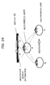
- FIG. 28 is a conceptual diagram illustrating an example of the display information change process according to the present embodiment.
- the diagram shows the position of the display 302 and the positions of the persons viewed from above: the position A is a place where the authorized user (browsing person) of the computer 301 is, the position B is a place where the unauthorized user (person who does not have the access right) was before the unauthorized user moved, and the position C is a place where the unauthorized user is after the unauthorized user moved.
- the display information change section 314 sets the position of a window where information is displayed at D on the display 302.
- the display information change section 314 sets the position of the window where information is displayed at E on the display 302.
- the display information change section 314 sets the position of the information-display window in a way that allows the authorized user to see the information but does not allow the unauthorized user to see the information. For example, the display information change section 314 places the information-display window on a straight line extending from the authorized user to the unauthorized user. Therefore, the unauthorized user's view of the display information is blocked by the authorized user, and the unauthorized user cannot see the display information.
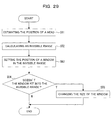
- FIG. 29 is a flowchart illustrating an example of the display information change process according to the present embodiment.
- the display information change section 314 estimates the position of the head of a person from the position of the person obtained by the position detection section 311 (S51). Then, the display information change section 314 calculates an invisible area on the display 302 (correspondence) that the unauthorized user cannot see, based on the position of the display 302, the position of the authorized user's head, and the position of the unauthorized user's head (positional relation)(S52). Then, the display information change section 314 sets the position of the information-display window within the invisible area (S53).
- the display information change section 314 makes a determination as to whether the information-display window does not fit into the invisible range. If the information-display window fits into the invisible range (S54, N), the flow comes to an end. If the information-display window does not fit into the invisible area (S54, Y), the display information change section 314 decreases the size of the information-display window so that the information-display window fits into the invisible area (S55), and the flow comes to end.
- the authorized user of the display information can continue work in accordance with the position of the unauthorized user. Therefore, the decrease in working efficiency can be prevented.
- each of the above-mentioned Embodiments 3, 4, and 5 can be combined with the other Embodiment 3, 4, or 5.
- the size of characters of the display information is also changed. Such a combination contributes to a further increase in security capability.
- each of the above-mentioned Embodiments 1, 2, 3, 4, and 5 can be combined with the other Embodiment 1, 2, 3, 4, or 5.
- the position of the display information is changed based on the position of the intruder; when the intruder enters the area A, work is suspended.
- Such a combination contributes to a further increase in security capability.
- a positional relation acquisition section corresponds to the position detection section 111 and the position prediction section 112, or the position detection section 311 and the display information change determination section 313 in the embodiments.
- a control section corresponds to the access control section 113, or the display information change section 314 in the embodiments.
- An authentication section corresponds to the authentication device 104, or the authentication section 312 in the embodiments.
- a positional relation acquisition step corresponds to the processes of S12 to S15, or the processes of S31 to S35 in the embodiments.
- a control step corresponds to the processes of S21 to S24, or the process of S43 in the embodiments.
- An authentication step corresponds to the process of the authentication device 104, or the process of the authentication section 312 in the embodiments.
- a program that causes a computer constituting the information processing apparatus to perform the above steps can be provided as an information processing program.
- the above-mentioned program is stored in a computer-readable recording medium, the above steps can be performed by the computer constituting the information processing apparatus.
- the above computer-readable recording medium includes: an internal storage device, such as ROM and RAM, which is mounted inside the computer; a portable storage medium such as CD-ROM, a flexible disk, a DVD disk, a magneto-optical disk, or an IC card; a database in which computer programs are stored; another computer and database thereof; and a transmission medium on a network line.
- the leakage of information displayed on the display device can be prevented.
Landscapes
- Engineering & Computer Science (AREA)
- Theoretical Computer Science (AREA)
- General Physics & Mathematics (AREA)
- Computer Hardware Design (AREA)
- Computer Security & Cryptography (AREA)
- Physics & Mathematics (AREA)
- General Engineering & Computer Science (AREA)
- Software Systems (AREA)
- Business, Economics & Management (AREA)
- Tourism & Hospitality (AREA)
- Computer Networks & Wireless Communication (AREA)
- Human Resources & Organizations (AREA)
- General Business, Economics & Management (AREA)
- Strategic Management (AREA)
- Primary Health Care (AREA)
- Marketing (AREA)
- General Health & Medical Sciences (AREA)
- Economics (AREA)
- Health & Medical Sciences (AREA)
- Controls And Circuits For Display Device (AREA)
- User Interface Of Digital Computer (AREA)
- Storage Device Security (AREA)
- Position Input By Displaying (AREA)
Applications Claiming Priority (1)
| Application Number | Priority Date | Filing Date | Title |
|---|---|---|---|
| PCT/JP2007/055357 WO2008126185A1 (fr) | 2007-03-16 | 2007-03-16 | Appareil de traitement d'informations, programme de traitement d'informations et procédé de traitement d'informations |
Publications (2)
| Publication Number | Publication Date |
|---|---|
| EP2128751A1 true EP2128751A1 (fr) | 2009-12-02 |
| EP2128751A4 EP2128751A4 (fr) | 2014-04-16 |
Family
ID=39863369
Family Applications (1)
| Application Number | Title | Priority Date | Filing Date |
|---|---|---|---|
| EP07738802.3A Withdrawn EP2128751A4 (fr) | 2007-03-16 | 2007-03-16 | Appareil de traitement d'informations, programme de traitement d'informations et procédé de traitement d'informations |
Country Status (6)
| Country | Link |
|---|---|
| US (1) | US20100005526A1 (fr) |
| EP (1) | EP2128751A4 (fr) |
| JP (1) | JP4829343B2 (fr) |
| KR (1) | KR101141847B1 (fr) |
| CN (1) | CN101641671B (fr) |
| WO (1) | WO2008126185A1 (fr) |
Cited By (5)
| Publication number | Priority date | Publication date | Assignee | Title |
|---|---|---|---|---|
| EP2870562A4 (fr) * | 2012-07-03 | 2016-03-09 | Intel Corp | Authentification continue à plusieurs facteurs |
| US20210208267A1 (en) * | 2018-09-14 | 2021-07-08 | Hewlett-Packard Development Company, L.P. | Device operation mode change |
| US11656532B2 (en) | 2021-06-16 | 2023-05-23 | Dell Products L.P. | Cylindrical camera dual leaf shutter |
| US11736789B2 (en) * | 2021-06-16 | 2023-08-22 | Dell Products L.P. | Peripheral camera and information handling system security system and method |
| US11971645B2 (en) | 2021-06-16 | 2024-04-30 | Dell Products L.P. | Cylindrical camera rotating cap shutter mechanism with enhanced audio security |
Families Citing this family (44)
| Publication number | Priority date | Publication date | Assignee | Title |
|---|---|---|---|---|
| WO2005086802A2 (fr) | 2004-03-08 | 2005-09-22 | Proxense, Llc | Systeme de compte lie utilisant une cle numerique personnelle |
| US11206664B2 (en) | 2006-01-06 | 2021-12-21 | Proxense, Llc | Wireless network synchronization of cells and client devices on a network |
| US8219129B2 (en) | 2006-01-06 | 2012-07-10 | Proxense, Llc | Dynamic real-time tiered client access |
| US8412949B2 (en) | 2006-05-05 | 2013-04-02 | Proxense, Llc | Personal digital key initialization and registration for secure transactions |
| WO2009062194A1 (fr) * | 2007-11-09 | 2009-05-14 | Proxense, Llc | Capteur de proximité de support de services d'applications multiples |
| US8171528B1 (en) | 2007-12-06 | 2012-05-01 | Proxense, Llc | Hybrid device having a personal digital key and receiver-decoder circuit and methods of use |
| US9251332B2 (en) | 2007-12-19 | 2016-02-02 | Proxense, Llc | Security system and method for controlling access to computing resources |
| US8508336B2 (en) | 2008-02-14 | 2013-08-13 | Proxense, Llc | Proximity-based healthcare management system with automatic access to private information |
| US11120449B2 (en) | 2008-04-08 | 2021-09-14 | Proxense, Llc | Automated service-based order processing |
| US20110292181A1 (en) * | 2008-04-16 | 2011-12-01 | Canesta, Inc. | Methods and systems using three-dimensional sensing for user interaction with applications |
| WO2010058683A1 (fr) * | 2008-11-21 | 2010-05-27 | コニカミノルタホールディングス株式会社 | Dispositif et procédé de lecture de données électroniques |
| JP2011188082A (ja) * | 2010-03-05 | 2011-09-22 | Shimizu Corp | ワークプレイス環境の管理システム |
| US9418205B2 (en) | 2010-03-15 | 2016-08-16 | Proxense, Llc | Proximity-based system for automatic application or data access and item tracking |
| TW201137742A (en) * | 2010-04-21 | 2011-11-01 | Hon Hai Prec Ind Co Ltd | Electronic device and prompting method thereof |
| US8670029B2 (en) * | 2010-06-16 | 2014-03-11 | Microsoft Corporation | Depth camera illuminator with superluminescent light-emitting diode |
| US8539560B2 (en) * | 2010-06-24 | 2013-09-17 | International Business Machines Corporation | Content protection using automatically selectable display surfaces |
| US8918854B1 (en) | 2010-07-15 | 2014-12-23 | Proxense, Llc | Proximity-based system for automatic application initialization |
| US9265450B1 (en) | 2011-02-21 | 2016-02-23 | Proxense, Llc | Proximity-based system for object tracking and automatic application initialization |
| JP5911251B2 (ja) * | 2011-09-29 | 2016-04-27 | キヤノン株式会社 | 画像処理装置、画像処理方法及びプログラム |
| JP5807575B2 (ja) * | 2012-02-09 | 2015-11-10 | 沖電気工業株式会社 | 顧客操作型端末装置及びその画面表示方法 |
| JP5974708B2 (ja) * | 2012-07-25 | 2016-08-23 | 株式会社リコー | 表示制御装置、表示制御方法およびプログラム |
| JP2014056345A (ja) * | 2012-09-11 | 2014-03-27 | Samsung R&D Institute Japan Co Ltd | 表示装置、および表示プログラム |
| US8925037B2 (en) * | 2013-01-02 | 2014-12-30 | Symantec Corporation | Systems and methods for enforcing data-loss-prevention policies using mobile sensors |
| JP2014153835A (ja) * | 2013-02-06 | 2014-08-25 | Ricoh Co Ltd | タップ制御装置、タップ制御方法およびプログラム |
| US20140226024A1 (en) * | 2013-02-08 | 2014-08-14 | Kutta Technologies, Inc. | Camera control in presence of latency |
| US9405898B2 (en) | 2013-05-10 | 2016-08-02 | Proxense, Llc | Secure element as a digital pocket |
| JP2016212451A (ja) * | 2013-09-11 | 2016-12-15 | 日本電気株式会社 | 秘密情報表示制御システム、サーバ、秘密情報表示制御方法およびプログラム |
| US20150170446A1 (en) * | 2013-12-12 | 2015-06-18 | Microsoft Corporation | Access tracking and restriction |
| JP6314918B2 (ja) * | 2015-06-19 | 2018-04-25 | コニカミノルタ株式会社 | 印刷装置 |
| JP2017054100A (ja) * | 2015-09-11 | 2017-03-16 | 株式会社東芝 | 表示制御装置および表示制御システム |
| WO2017088007A1 (fr) * | 2015-11-25 | 2017-06-01 | Vac Group Operations Pty Ltd | Dispositif de sécurité de site de travail utilisant un lidar |
| US10404697B1 (en) | 2015-12-28 | 2019-09-03 | Symantec Corporation | Systems and methods for using vehicles as information sources for knowledge-based authentication |
| US10326733B2 (en) | 2015-12-30 | 2019-06-18 | Symantec Corporation | Systems and methods for facilitating single sign-on for multiple devices |
| US10375114B1 (en) | 2016-06-27 | 2019-08-06 | Symantec Corporation | Systems and methods for enforcing access-control policies |
| US10462184B1 (en) | 2016-06-28 | 2019-10-29 | Symantec Corporation | Systems and methods for enforcing access-control policies in an arbitrary physical space |
| US10469457B1 (en) | 2016-09-26 | 2019-11-05 | Symantec Corporation | Systems and methods for securely sharing cloud-service credentials within a network of computing devices |
| US10812981B1 (en) | 2017-03-22 | 2020-10-20 | NortonLifeLock, Inc. | Systems and methods for certifying geolocation coordinates of computing devices |
| CN107942692B (zh) * | 2017-12-01 | 2021-10-19 | 百度在线网络技术(北京)有限公司 | 信息显示方法和装置 |
| CN109284640A (zh) * | 2018-10-17 | 2019-01-29 | 深圳超多维科技有限公司 | 一种防窥的方法、装置、电子设备及立体显示设备 |
| US11281771B2 (en) * | 2019-07-30 | 2022-03-22 | Bank Of America Corporation | Preventing unauthorized screen capture activity |
| CN110572530A (zh) * | 2019-08-23 | 2019-12-13 | 苏州佳世达光电有限公司 | 保护个人隐私的影像呈现方法及装置 |
| US11431917B2 (en) * | 2020-10-12 | 2022-08-30 | Dell Products L.P. | System and method of operating a display associated with an information handling system |
| US12079639B2 (en) * | 2021-04-01 | 2024-09-03 | Motorola Mobility Llc | Automatically changing device property values for a secondary user of a device |
| JP7294376B2 (ja) * | 2021-07-19 | 2023-06-20 | 株式会社明電舎 | 車速制御装置及びドライバモデル処理装置 |
Citations (4)
| Publication number | Priority date | Publication date | Assignee | Title |
|---|---|---|---|---|
| WO2003102744A2 (fr) * | 2002-06-04 | 2003-12-11 | Sap Aktiengesellschaft | Systeme d'affichage sensible |
| US20050086515A1 (en) * | 2003-10-15 | 2005-04-21 | Paris Clifford D. | Motion detecting computer control device |
| EP1607843A2 (fr) * | 2004-05-24 | 2005-12-21 | Microsoft Corporation | Limitation d'affichage d'informations avec un objet physique |
| EP1760621A1 (fr) * | 2005-08-30 | 2007-03-07 | Sap Ag | Contrôle des informations dans l'interaction fédérée |
Family Cites Families (9)
| Publication number | Priority date | Publication date | Assignee | Title |
|---|---|---|---|---|
| JP3205081B2 (ja) * | 1992-08-11 | 2001-09-04 | 株式会社リコー | 電子装置 |
| US5422656A (en) * | 1993-11-01 | 1995-06-06 | International Business Machines Corp. | Personal communicator having improved contrast control for a liquid crystal, touch sensitive display |
| JP3617882B2 (ja) * | 1996-03-08 | 2005-02-09 | 株式会社東芝 | セキュリティ装置及びセキュリティ実現方法 |
| US6501846B1 (en) * | 1997-11-25 | 2002-12-31 | Ethentica, Inc. | Method and system for computer access and cursor control using a relief object image generator |
| KR20020007823A (ko) * | 2000-07-19 | 2002-01-29 | 장용우 | 지문인식을 이용한 보안/모니터링시스템 및 그 제어방법 |
| JP2005107306A (ja) | 2003-09-30 | 2005-04-21 | Sharp Corp | 液晶表示構造体 |
| JP2005346307A (ja) | 2004-06-01 | 2005-12-15 | Canon Inc | 電子ドキュメント閲覧装置およびその制御方法 |
| JP4628851B2 (ja) | 2005-04-22 | 2011-02-09 | 富士通株式会社 | 物体検出方法および物体検出装置 |
| US20070083915A1 (en) * | 2005-10-06 | 2007-04-12 | Janani Janakiraman | Method and system for dynamic adjustment of computer security based on personal proximity |
-
2007
- 2007-03-16 JP JP2009508736A patent/JP4829343B2/ja not_active Expired - Fee Related
- 2007-03-16 WO PCT/JP2007/055357 patent/WO2008126185A1/fr active Application Filing
- 2007-03-16 EP EP07738802.3A patent/EP2128751A4/fr not_active Withdrawn
- 2007-03-16 KR KR1020097019346A patent/KR101141847B1/ko not_active IP Right Cessation
- 2007-03-16 CN CN2007800521810A patent/CN101641671B/zh not_active Expired - Fee Related
-
2009
- 2009-09-11 US US12/557,778 patent/US20100005526A1/en not_active Abandoned
Patent Citations (4)
| Publication number | Priority date | Publication date | Assignee | Title |
|---|---|---|---|---|
| WO2003102744A2 (fr) * | 2002-06-04 | 2003-12-11 | Sap Aktiengesellschaft | Systeme d'affichage sensible |
| US20050086515A1 (en) * | 2003-10-15 | 2005-04-21 | Paris Clifford D. | Motion detecting computer control device |
| EP1607843A2 (fr) * | 2004-05-24 | 2005-12-21 | Microsoft Corporation | Limitation d'affichage d'informations avec un objet physique |
| EP1760621A1 (fr) * | 2005-08-30 | 2007-03-07 | Sap Ag | Contrôle des informations dans l'interaction fédérée |
Non-Patent Citations (1)
| Title |
|---|
| See also references of WO2008126185A1 * |
Cited By (5)
| Publication number | Priority date | Publication date | Assignee | Title |
|---|---|---|---|---|
| EP2870562A4 (fr) * | 2012-07-03 | 2016-03-09 | Intel Corp | Authentification continue à plusieurs facteurs |
| US20210208267A1 (en) * | 2018-09-14 | 2021-07-08 | Hewlett-Packard Development Company, L.P. | Device operation mode change |
| US11656532B2 (en) | 2021-06-16 | 2023-05-23 | Dell Products L.P. | Cylindrical camera dual leaf shutter |
| US11736789B2 (en) * | 2021-06-16 | 2023-08-22 | Dell Products L.P. | Peripheral camera and information handling system security system and method |
| US11971645B2 (en) | 2021-06-16 | 2024-04-30 | Dell Products L.P. | Cylindrical camera rotating cap shutter mechanism with enhanced audio security |
Also Published As
| Publication number | Publication date |
|---|---|
| CN101641671B (zh) | 2011-09-07 |
| JPWO2008126185A1 (ja) | 2010-07-22 |
| US20100005526A1 (en) | 2010-01-07 |
| EP2128751A4 (fr) | 2014-04-16 |
| WO2008126185A1 (fr) | 2008-10-23 |
| JP4829343B2 (ja) | 2011-12-07 |
| KR20100005028A (ko) | 2010-01-13 |
| CN101641671A (zh) | 2010-02-03 |
| KR101141847B1 (ko) | 2012-05-07 |
Similar Documents
| Publication | Publication Date | Title |
|---|---|---|
| EP2128751A1 (fr) | Appareil de traitement d'informations, programme de traitement d'informations et procédé de traitement d'informations | |
| US20210201269A1 (en) | Methods and System for Employee Monitoring and Business Rule and Quorum Compliance Monitoring | |
| AU2006200828B2 (en) | Face authenticating apparatus and entrance and exit management apparatus | |
| JP2007303239A (ja) | 認証装置、認証装置の制御方法、および認証装置の制御プログラム | |
| KR20180051191A (ko) | 영상처리장치 및 그의 영상제공방법 | |
| KR102012672B1 (ko) | 얼굴인식 기반의 사람 특징인식을 이용한 방범 시스템 및 방법 | |
| JP2006259930A (ja) | 表示装置およびその制御方法、表示装置を備えた電子機器、表示装置制御プログラム、ならびに該プログラムを記録した記録媒体 | |
| US20090303040A1 (en) | System and method for dynamic association of security levels and enforcement of physical security procedures | |
| CN111989671B (zh) | 安全系统 | |
| JP2008108243A (ja) | 人物認識装置および人物認識方法 | |
| JP5900941B1 (ja) | デジタルフューチャーナウ・セキュリティシステム、方法及びプログラム | |
| JP2005084815A (ja) | 顔認識装置、顔認識方法および通行制御装置 | |
| KR20170080739A (ko) | Qr코드를 이용한 외부 출입자 관리시스템 및 그 제어방법 | |
| KR20100010325A (ko) | 객체 추적 방법 | |
| US20220415108A1 (en) | Indication system and a method for generating an indication | |
| US20230010991A1 (en) | Access control system and a method for controlling operation of an access control system | |
| KR102033057B1 (ko) | 사각지대 객체 감지를 이용하여 상황을 인지하는 방법 및 디지털 도어락 장치 | |
| CN113791408B (zh) | 室内定位目标对象的方法、装置和存储介质 | |
| Gavaskar et al. | A novel design and implementation of IoT based real-time ATM surveillance and security system | |
| KR100787005B1 (ko) | 카메라를 내장한 비접촉식 카드 리더기를 이용한 출입통제시스템과 출입통제 방법 | |
| JP5649862B2 (ja) | 画像監視装置 | |
| CN109712355A (zh) | 房屋安全监控方法、智能设备及门锁 | |
| KR20180003897A (ko) | 전자 문서의 유출 방지 방법, 디바이스 및 컴퓨터 판독가능 매체 | |
| KR101276936B1 (ko) | 추적 대상 통제 방법 및 이를 위한 지능형 로봇 감시서비스 시스템 | |
| EP4016480A1 (fr) | Détection et reconnaissance faciale de capture d'écran de système de contrôle d'accès |
Legal Events
| Date | Code | Title | Description |
|---|---|---|---|
| PUAI | Public reference made under article 153(3) epc to a published international application that has entered the european phase |
Free format text: ORIGINAL CODE: 0009012 |
|
| 17P | Request for examination filed |
Effective date: 20090916 |
|
| AK | Designated contracting states |
Kind code of ref document: A1 Designated state(s): AT BE BG CH CY CZ DE DK EE ES FI FR GB GR HU IE IS IT LI LT LU LV MC MT NL PL PT RO SE SI SK TR |
|
| DAX | Request for extension of the european patent (deleted) | ||
| A4 | Supplementary search report drawn up and despatched |
Effective date: 20140314 |
|
| RIC1 | Information provided on ipc code assigned before grant |
Ipc: G06F 21/84 20130101AFI20140310BHEP Ipc: G06F 21/35 20130101ALI20140310BHEP Ipc: G06F 21/88 20130101ALI20140310BHEP Ipc: G06F 3/048 20130101ALI20140310BHEP |
|
| STAA | Information on the status of an ep patent application or granted ep patent |
Free format text: STATUS: THE APPLICATION HAS BEEN WITHDRAWN |
|
| 18W | Application withdrawn |
Effective date: 20180124 |
|
| RIC1 | Information provided on ipc code assigned before grant |
Ipc: G06F 3/048 20130101ALI20140310BHEP Ipc: G06F 21/88 20130101ALI20140310BHEP Ipc: G06F 21/35 20130101ALI20140310BHEP Ipc: G06F 21/84 20130101AFI20140310BHEP |
|
| RIC1 | Information provided on ipc code assigned before grant |
Ipc: G06F 21/88 20130101ALI20140310BHEP Ipc: G06F 21/35 20130101ALI20140310BHEP Ipc: G06F 21/84 20130101AFI20140310BHEP Ipc: G06F 3/048 20130101ALI20140310BHEP |