EP2126636B1 - Système d'éclairage d'un appareil d'exposition par projection pour microlithographie - Google Patents
Système d'éclairage d'un appareil d'exposition par projection pour microlithographie Download PDFInfo
- Publication number
- EP2126636B1 EP2126636B1 EP08715667A EP08715667A EP2126636B1 EP 2126636 B1 EP2126636 B1 EP 2126636B1 EP 08715667 A EP08715667 A EP 08715667A EP 08715667 A EP08715667 A EP 08715667A EP 2126636 B1 EP2126636 B1 EP 2126636B1
- Authority
- EP
- European Patent Office
- Prior art keywords
- filter
- illumination system
- transmittance
- field
- transmission
- Prior art date
- Legal status (The legal status is an assumption and is not a legal conclusion. Google has not performed a legal analysis and makes no representation as to the accuracy of the status listed.)
- Not-in-force
Links
Images


Classifications
-
- G—PHYSICS
- G03—PHOTOGRAPHY; CINEMATOGRAPHY; ANALOGOUS TECHNIQUES USING WAVES OTHER THAN OPTICAL WAVES; ELECTROGRAPHY; HOLOGRAPHY
- G03F—PHOTOMECHANICAL PRODUCTION OF TEXTURED OR PATTERNED SURFACES, e.g. FOR PRINTING, FOR PROCESSING OF SEMICONDUCTOR DEVICES; MATERIALS THEREFOR; ORIGINALS THEREFOR; APPARATUS SPECIALLY ADAPTED THEREFOR
- G03F7/00—Photomechanical, e.g. photolithographic, production of textured or patterned surfaces, e.g. printing surfaces; Materials therefor, e.g. comprising photoresists; Apparatus specially adapted therefor
- G03F7/70—Microphotolithographic exposure; Apparatus therefor
- G03F7/70058—Mask illumination systems
- G03F7/70191—Optical correction elements, filters or phase plates for controlling intensity, wavelength, polarisation, phase or the like
-
- G—PHYSICS
- G02—OPTICS
- G02B—OPTICAL ELEMENTS, SYSTEMS OR APPARATUS
- G02B27/00—Optical systems or apparatus not provided for by any of the groups G02B1/00 - G02B26/00, G02B30/00
- G02B27/10—Beam splitting or combining systems
Definitions
- the invention relates to an illumination system of a microlithographic projection exposure apparatus.
- the invention relates in particular to an illumination system with which the illumination angle distribution of the light incident on the mask can be symmetrised better.
- Integrated electrical circuits and other microstructured components are conventionally produced by applying a plurality of structured layers onto a suitable substrate which, for example, may be a silicon wafer.
- a suitable substrate which, for example, may be a silicon wafer.
- the layers are first covered with a photoresist which is sensitive to light of a particular wavelength range, for example light in the deep ultraviolet (DUV) spectral range.
- the wafer coated in this way is subsequently exposed in a projection exposure apparatus.
- a pattern of diffracting structures, which is arranged on a mask, is thereby imaged onto the photoresist with the aid of a projection objective. Since the imaging scale is generally less than 1, such projection objectives are often also referred to as reducing objectives.
- the wafer is subjected to an etching process so that the layer becomes structured according to the pattern on the mask.
- the remaining photoresist is then removed from the other parts of the layer. This process is repeated until all the layers have been applied on the wafer.
- the performance of the projection exposure apparatus being used is determined not only by the imaging properties of the projection objective but also by an illumination system which illuminates the mask.
- the illumination system contains a light source, for example a laser operated in pulsed mode, and a plurality of optical elements which generate light bundles, converging on the mask at field points, from the light generated by the light source.
- the individual light bundles must have particular properties, which in general are adapted to the projection objective.
- illumination angle distribution describes the way in which the overall intensity of a light bundle is distributed between the different directions in which the individual rays of the light bundle strike the relevant point in the mask plane. If the illumination angle distribution is specially adapted to the pattern contained in the mask, then the latter can be imaged with high imaging quality onto the wafer covered with photoresist.
- the illumination angle distribution is often not described directly in the mask plane, in which the mask to be projected is placed, but instead as an intensity distribution in a pupil plane which has a Fourier relation with the mask plane.
- This utilises the fact that each angle with respect to the optical axis, at which a light ray passes through a field plane, can be assigned a radial distance measured from the optical axis in a Fourier-transformed pupil plane.
- the region illuminated in such a pupil plane is a circular disc concentric with the optical axis.
- Each point in the mask plane is therefore struck by light rays at angles of incidence of between 0° and a maximum angle dictated by the radius of the circular disc.
- the region illuminated in the pupil plane has the shape of a ring concentric with the optical axis, or a plurality of individual regions (poles) which are arranged at a distance from the optical axis.
- the mask to be projected is illuminated exclusively obliquely.
- the illumination angle distribution is rotationally symmetric in the ideal case.
- the illumination angle distribution is ideally not rotationally symmetric, in the ideal case the poles in the pupil plane are illuminated so that the illumination angle distribution has a fourfold symmetry. Expressed more simply, an equal amount of light from all four directions therefore strikes a field point in the mask plane.
- the symmetry properties of the respective illumination angle distribution are very important for dimensionally accurate imaging of the structures contained on the masks.
- structures which are equally wide but oriented differently on the mask may be imaged with a different width on the photoresist. This can compromise unimpaired function of the microlithographically produced components.
- the term pupil ellipticity is often used.
- the pupil ellipticity corresponds to the ratio of the amounts of light which strike a field point on the mask from orthogonal directions during an exposure. The more the pupil ellipticity deviates from 1, the more asymmetric is the illumination angle distribution.
- telecentricity Another property of the light bundles striking the mask plane is the telecentricity.
- the term telecentric illumination is used when the energetically central rays of the light bundle, which are generally referred to as principal or centroid rays, pass perpendicularly through the mask plane. With non-telecentric illumination, the entire light bundle strikes the mask to some extent obliquely. For the illumination angle distribution, this means that the different amounts of light come from opposite directions. In general, telecentric illumination is desired since the projection objectives are usually also telecentric on the object side. When correcting the pupil ellipticity, therefore, the telecentricity should generally be preserved.
- a variable transmission filter which is arranged in a pupil plane of the illumination system, is known from US 6 535 274 B2 .
- the transmission filter is configured as a grey filter, and therefore contains regions in which the transmission coefficient lies between 0 and 100%. These regions make it possible to attenuate parts of the projection light so that the pupil ellipticity is reduced. The fact that there is a unique equivalence between positions in a pupil plane and angles in a field plane is thereby utilised. Owing to the arrangement in a pupil plane, the attenuation - and therefore the correction of the pupil ellipticity - is the same for all points illuminated in the mask plane.
- Transmission filters which are also arranged in a pupil plane of an illumination system, are known from WO 2005/006079 A , US 2004/0257559 A , US 2002/0075468 A , and US 5 863 712 A .
- EP 1 798 758 A1 discloses an illumination system having a pair of transmission filters which make it possible to correct field-dependent telecentricity errors without affecting the total irradiance distribution.
- a first filter having in one direction a "concave" transmission profile is arranged at a small distance in front of, and a second transmission filter having in the same direction a complementary "convex" transmission profile is arranged at the same small distance behind an intermediate field plane in which a field stop of of the illumination system is positioned. Since the light bundles are "inverted" when passing through the field plane, the second filter adds to the asymmetry of the light bundle's energy distribution introduced by the first filter, and thus both filters affect the telecentricity.
- the combination of both filters having complementary transmission profiles ensures that the irradiance on the mask in not affected.
- US 2003/0067591 A1 describes an illumination system in which two transmission filters are arranged in a field plane which is optically conjugated to a mask plane in which a mask to be illuminated is can be arranged.
- the transmission filters which each contain a large number of opaque dots having a varying density, are provided to improve the uniformity of the mask illumination. In order to avoid that the opaque dots are sharply imaged on the mask, the transmission filters are positioned slightly outside the field plane.
- US 2007/0229790 A1 which has been published after the priority date of the present application, discloses a transmission filter that is arranged in an interspace between an illumination system and a projection objective of a microlithographic exposure apparatus.
- Another illumination system having a transmission filter arranged in a field plane is disclosed, for example, in WO 2005/015310 A2 .
- the pupil ellipticity is not generally the same at all points illuminated on the mask. To date, the field dependency of the pupil ellipticity has been negligible; the stringent requirements which will be placed on future illumination systems, however, demand measures by which field-dependent pupil ellipticities can be corrected.
- the filter known from US 6 535 274 B2 cited above, is adjustable so that different field-constant ellipticities can be corrected. A field-dependent pupil ellipticity, however, cannot be corrected in this way.
- the illumination system should be capable of correcting the pupil ellipticity without thereby causing perturbations of the telecentric properties.
- an illumination system of a microlithographic projection exposure apparatus as defined is claim 1, in which a mask is displaced along a scan direction during an exposure of a photosensitive layer.
- the illumination system comprises a pupil plane, a field plane and a transmission filter, which has a different transmittance at least at two positions.
- the transmission filter is arranged between the pupil plane and the field plane.
- the transmission filter Since the transmission filter is not arranged in a pupil plane, unlike in the prior art, the effect of the transmission filter is no longer the same for all field points.
- the effect achieved by arranging the transmission filter outside a field plane, on the other hand, is that the transmission filter modifies the illumination angle distribution and not only the intensity at a field point.
- the field illuminated on the mask regularly has the shape of a slit which, for example, may be rectangular or have the shape of a ring segment.
- the illuminated field may also be off-axial so that the optical axis of the illumination system does not extend through the middle of the illuminated field, or even extends outside it.
- a light field which has shorter dimensions parallel to the scan direction than perpendicularly thereto, is illuminated on the transmission filter during the exposure.
- the transmission filter is positioned at a distance from the pupil plane and the field plane such that a bundle of light rays, all of which pass through a point in the field plane, crosses the transmission filter with a maximum diameter which is less than L x /2 and greater than L y /30, where L x is the length of the light field perpendicularly to the scan direction and L y is the length of the light field along the scan direction.
- the size of the light field which is illuminated on the transmission filter depends not only on the geometry of the illuminated field, but also on the adjusted illumination setting. When there is a change in the illumination setting, therefore, the size of the light field illuminated on the transmission filter is modified and consequently so is the effect of the transmission filter on the illumination angle distribution.
- a manipulator may be provided for continuously varying the position of the transmission filter along the optical axis. In this way, the size of the illuminated light field can be modified straightforwardly by displacing the transmission filter along the optical axis.
- Stepwise adaptation is achievable with very simple means if the illumination system comprises at least two exchange holders for holding the transmission filter, which are arranged at different positions along the optical axis.
- the adaptation is then carried out by transferring the transmission filter from one exchange holder into the other.
- the transmission filter has at least one first filter region which has a transmittance that varies perpendicularly to the scan direction. Only with a transmittance varying in this way the desired field dependency of the effect on the illumination angle distribution can be achieved. This is because owing to the integration of the light energy during the scan process, although variations of the transmittance parallel to the scan direction have an effect on the illumination angle distribution at a specific time, they have virtually no effect on the "integrated" pupil ellipticity.
- the light field may have two mutually opposite first edges which delimit the light field along the scan direction, and two mutually opposite second edges which delimit the light field perpendicularly to the scan direction.
- the first filter region extends at least as far as one of the first edges in this configuration. An asymmetrisation is achieved in this way, since only some of the light rays which arrive on a particular field point throughout the exposure process will pass through such a first filter region. Such an asymmetrisation is necessary so that a pupil ellipticity can be corrected.
- the pupil ellipticity varies continuously perpendicularly to the scan direction. Accordingly, for optimal correction, the transmittance of the first filter region should also vary continuously perpendicularly to the scan direction.
- the field dependency of the pupil ellipticity is mirror-symmetric with respect to a symmetry plane which extends parallel to the scan direction and contains an optical axis of the illumination system.
- the transmittance in the first filter region likewise to have a spatial distribution which is mirror-symmetric with respect to this symmetry plane.
- a transmission filter suitable for the correction then contains a first filter region, the transmittance of which decreases continuously as the distance to the second edges decreases.
- the transmission filter should comprise two first filter regions, each of which has a transmittance that varies perpendicularly to the scan direction. It is furthermore preferable in this case for the spatial distributions of the transmittance of both first filter regions to be identical.
- the two first filter regions may, for example, be designed as sub-elements which are displaceable along the scan direction. In this way, the corrective effect can readily be modified by displacing the sub-elements along the scan direction. By means of this, for example, adaptation to different illumination settings is possible in a very straightforward way.
- the field-dependent attenuation of light rays with the aid of the first filter region entails a field-dependent variation of the overall radiation dose. Since this effect is generally undesirable, corresponding countermeasures need to be implemented.
- One possibility for this consists in using devices known per se in order to homogenise the radiation dose.
- the use of field diaphragms may for example be envisaged, the diaphragm elements of which comprise a multiplicity of individual finger-like diaphragm elements displaceable independently of one another.
- a grey filter which is arranged in or in the immediate vicinity of an intermediate field plane may be used in order to homogenise the radiation dose.
- the transmission filter itself may nevertheless also ensure a corresponding correction of the overall radiation dose if a second filter region is provided, which has a spatial distribution of the transmittance perpendicularly to the scan direction that is qualitatively opposite to the spatial distribution of the transmittance of the first filter region.
- a second filter region which has a spatial distribution of the transmittance perpendicularly to the scan direction that is qualitatively opposite to the spatial distribution of the transmittance of the first filter region.
- a microlithographic projection exposure apparatus comprises a plurality of pupil planes, a plurality of field planes and two transmission filters.
- the filters have spatial transmittance distributions that are either identical or differ only by a scaling factor. This means that one filter may be considered as a minified or magnified image of the other filter.
- the scaling factor is determined by the difference of the diameter of a light bundle when it passes through the filters. Such a scaling ensures that the same conditions prevail for both light bundles even if their diameters on the filters are different.
- the filters are either separated from each other by n pupil planes and n+1 or n-1 field planes, wherein n is an odd integer, or by m field planes and m+1 or m-1 pupil planes, wherein m is an even integer distinct from zero.
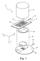
- Figure 1 is a highly schematised perspective representation of a projection exposure apparatus 10, which is suitable for the lithographic production of microstructured components.
- the projection exposure apparatus 10 contains an illumination system 12 that illuminates a narrow illuminated field 16, which is rectangular in the embodiment represented, on a mask 14.
- Other illuminated field shapes, for example ring segments, may of course likewise be envisaged.
- Structures 18 lying inside the illuminated field 16 on the mask 14 are imaged with the aid of a projection objective 20 onto a photosensitive layer 22.
- the photosensitive layer 22, which may for example be a photoresist, is applied on wafer 24 or another suitable substrate and lies in the image plane of the projection objective. Since the projection objective 20 generally has an imaging scale ⁇ ⁇ 1, structures 18 lying inside the illuminated field 16 are imaged in a reduced fashion as region 16'.
- the mask 14 and the wafer 24 are displaced along a direction denoted by Y during the projection.
- the ratio of the displacement rates is equal to the imaging scale ⁇ of the projection objective 20. If the projection objective 20 generates inversion of the image, then the displacement movements of the mask 14 and the wafer 22 will be in opposite directions as is indicated by arrows A1 and A2 in Figure 1 . In this way, the illuminated field 16 is guided in a scanning movement over the mask 14 so that even sizeable structured regions can be projected coherently onto the photosensitive layer 22.
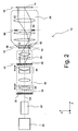
- FIG. 2 shows details of the illumination system 12 according to a first group of embodiments in a simplified meridional section which is not true to scale.
- the illumination system 12 contains a light source 26, which generates projection light.
- the light source 26 is an excimer laser with which light in the (deep) ultraviolet spectral range can be generated.
- the use of short-wave projection light is advantageous because a high resolution can thereby be achieved for the optical imaging.
- Excimer lasers with the laser media KrF, ArF or F 2 by which light with the wavelengths 248 nm, 193 nm and 157 nm can respectively be generated, are conventional.
- the light generated by the excimer laser used as a light source 26 is highly collimated and diverges only weakly. It is therefore initially expanded in a beam expander 28.
- the beam expander 28 may for example be an adjustable mirror arrangement, which increases the dimensions of the approximately rectangular light beam cross section.
- the expanded light beam subsequently passes through a diffractive optical element 36, held in an exchange holder 30, and a zoom-axicon module 38, which together illuminate a first pupil plane 42 of the illumination system.
- the zoom-axicon module 38 comprises a zoom objective denoted by 44 and an axicon group 46, which contains two axicon elements with conical and mutually complementary faces. With the aid of the axicon group 46, the radial light distribution can be modified so as to achieve annular illumination of the first pupil plane 42. By adjusting the zoom objective 44, it is possible to modify the diameter of the regions illuminated in the first pupil plane 42.
- the zoom-axicon module 38 therefore makes it possible to adjust various conventional and annular illumination settings.
- a suitable diffractive optical element 36 is inserted into the exchange holder 30.
- the angle distribution generated by the diffractive optical element 36 is selected so that the desired arrangement of poles is illuminated in the first pupil plane 42.
- An optical integrator 48 which may for example be an arrangement of microlens arrays, is arranged in or in the immediate vicinity of the first pupil plane 42.
- Each microlens constitutes a secondary light source, which generates a divergent light bundles with an angle spectrum predetermined by the geometry of the microlens.
- the light bundles generated by the secondary light sources are superimposed by a condenser 50 in an intermediate field plane 52, so that the latter is illuminated very homogeneously.
- the condenser 50 establishes a Fourier relation between the first pupil plane 42 and the intermediate field plane 52. All light rays emerging at the same angle from the first pupil plane 42 therefore arrive at the same point in the intermediate field plane 52, whereas all light rays emerging from a particular point in the first pupil plane 42 pass through the intermediate field plane 52 at the same angle.
- a field diaphragm 54 which may for example comprise a plurality of adjustable blades and/or a multiplicity of narrow finger-like diaphragm elements which can be inserted independently of one another into the light path, is arranged in the intermediate field plane 52.
- the intermediate field plane 52 is optically conjugated with a mask plane 58 in which the mask 14 is arranged.
- the mask plane 58 is both the image plane of the field diaphragm objective 56 and the object plane of the subsequent projection objective 20.
- the field diaphragm objective 56 is schematically indicated with only three lenses in Figure 2 .
- High-quality field diaphragm objectives such as are described for example in US 2004/0207928 A1 and WO 2006/114294 A2 , generally have more than three lenses.
- the principal rays a single one of which is represented by way of example in Figure 2 and denoted by 62, intersect the optical axis OA in a second pupil plane 60 of the illumination system 12.
- An aperture diaphragm 64 which restricts the aperture of the field aperture objective 56, is arranged in the second pupil plane 60.
- transmission filter 66 Between the intermediate field plane 52 and the second pupil plane 60, there is a transmission filter 66 whose possible configurations will be discussed below.
- the purpose of the transmission filter 66 is to correct the illumination angle distribution, for example by reducing undesired asymmetries. What this specifically entails will be explained in more detail below with the aid of Figures 3 to 5 .
- Figure 3 shows, in a perspective schematic representation, the pupil plane 60 of the field diaphragm objective 56 as well as a detail of the mask plane 58.
- the diffractive optical element 36 may be configured so that four poles in the first pupil plane 42 are illuminated. Since the illumination angle distribution is not changed by the condenser 50 and by the field diaphragm 54, four poles are also illuminated in the pupil plane 60 of the field diaphragm objective 56, which are denoted by 68a, 68b, 68c and 68d in Figure 3 .
- the light bundles, which illuminate the poles 68a to 68d, are denoted respectively by 70a, 70b, 70c and 70d and converge at a field point 72 in the mask plane 58. All the light bundles 70a to 70d therefore contribute to the intensity at the field point 72.
- the term pupil ellipticity is often employer.
- the local pupil assigned to the relevant field point is considered.
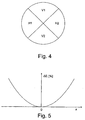
- the local pupil is subdivided into four segments, as shown in Figure 4 .
- the two segments lying vertically above one another are denoted by V1 and V2, and the segments lying horizontally next to one another are denoted by H1 and H2.
- This type of description is furthermore illustrated in Figure 3 , in which the individual segments V1, V2, H1 and H2 are separated from one another by dashed lines.
- the values D V1 , D V2 , D H1 and D H2 of the integrated radiation dose in the individual segments of the local pupil are then determined.
- the radiation dose is the radiation energy arriving at the field point throughout the exposure process. In photometry, this quantity is generally referred to not as a radiation dose but as irradiation.
- the unit of the radiation dose is Joule per square millimetre (J/mm 2 ).
- the integration of the radiation dose in the segments of the local pupil may be carried out by means of simulation, or alternatively by measurement techniques.
- the deviation of the value of the pupil ellipticity E from 1 is a measure of how greatly the intensities of the pairwise opposite light bundles 70a, 70c on the one hand, and 70b, 70d on the other hand, differ from one another. The greater the deviation is from one, the more it is to be expected that equally wide horizontally and vertically oriented structures on the mask will be imaged with different widths onto the photosensitive layer 22.
- One cause may for example be that the diffractive optical element 30 has different diffraction efficiencies for diffraction in horizontal and vertical directions.
- the light bundles which are assigned to individual field points in the mask plane 58, generally travel different paths through the optical element of the illumination system 12. Since the illumination system 12 does not have the same overall transmittance for all paths, the pupil ellipticity E may take different values depending on the field point in question.
- Figure 5 is a graph in which the percentage deviation ⁇ E of the pupil ellipticity E from the value 1 is plotted by way of example, and merely qualitatively, as a function of the distance x from the field centre along the X direction i.e. perpendicularly to the scan direction Y.
- the deviation ⁇ E has an at least approximately parabolic profile and therefore increases significantly towards the lateral edges of the illuminated field 16. Since the illuminated field 16 has substantially shorter dimensions along the scan direction Y than perpendicularly thereto, the pupil ellipticity changes only insubstantially along the scan direction.
- the pupil ellipticity must be referenced to the individual mask points. This simply means that the radiation dose is integrated not for a fixed field point but for a mask point during the scan process. Since a mask point moves through the illuminated field 16 during the scan process, it will to a certain extent be exposed to the pupil ellipticities of all field points which the mask point moves over during the scan process. Consequently, it is therefore predominantly mask points and not field points which are important in connection with the pupil ellipticity.
- a first embodiment of a transmission filter 66 with which such a field-dependent pupil ellipticity can be corrected, will be explained below with the aid of Figures 6 as well as 7a, 7b and 7c.
- Figure 6 shows the transmission filter 66 in a plan view, the various transmissivities being indicated by grey values. The darker an area is, the more strongly light passing through is absorbed, and vice versa.
- the different grey values may for example be generated by continuously varying blackening, which is applied onto a transparent support.
- blackening As an alternative to this, in the manner of a digital transmission filter, it is possible to apply a large number of individual opaque points onto a support, the size and/or density of which points varies over the surface.
- Transmission filters with a spatially varying transmittance are often also referred to as grey filters.
- the transmission filter 66 essentially has the dimensions of a light field through which projection light passes at the position of the transmission filter 66 as shown in Figure 2 , between the intermediate field plane 52 and the second pupil plane 60.
- the transmission filter 66 is in any event configured so that it may be larger but not smaller than this light field.
- the transmission filter 66 may of course also have a circular contour, as is conventional for optical elements and also expedient with a view to mounting in standardised frames.
- the transmission filter has upper and lower longitudinal edges 74a and 74b, respectively, which extend parallel to the X direction i.e. perpendicularly to the scan direction Y.
- the two shorter left- and right-hand side edges are denoted by 76a and 76b in Figure 6 .
- the transmittance of the first filter regions 78a, 78b depends merely on the X coordinate, but not on the Y coordinate.
- the distribution of the transmittance of the first filter regions 78a, 78b is mirror-symmetric with respect to a symmetry plane 79.
- the symmetry plane 79 in this case extends through the centre of the light field and contains the optical axis OA.
- the transmittance decreases in the X direction with an increasing distance x from the symmetry plane 79, for example with a dependency ⁇ x 4 .
- the distribution of the transmittance of the second filter region 80 which occupies the area between the first filter regions 78a, 78b.
- the spatial distribution of the transmittance in the second filter region 80 is qualitatively opposite to the spatial distribution of the transmittance of the first filter regions 78a, 78b. The lowest transmittance is therefore achieved in the field centre, whereas it increases continuously to the side edges 76a, 76b.
- Figures 7a to 7c show the transmission filter 66 at three different times during a scan process.
- the illuminated field 16 is respectively indicated by a dashed line (or a field conjugate therewith in the intermediate field plane 52).
- a mask point 82 which lies at the left-hand edge of the illuminated field 16 illuminated on the mask 14, will be considered first.
- Figure 7a shows the position of the mask point 82 at the time when light initially strikes the mask point 82 during the scan process, which is indicated by the arrow 84.
- a circle indicates the (maximum) diameter of a light bundle 84, the rays of which converge on the mask point 82 at this time.
- the light bundle 84 passes through only a part of the transmission filter 66.
- the arrangement of the first filter regions 78a, 78b is in this case adapted to the diameter of the light bundle 84 so that a part of the light bundle 84 passes through the upper first filter region 78a at the time shown in Figure 7a . Some of the light rays, which strike the mask point 82, are therefore attenuated by the upper first filter region 78a at this time.
- the cross section of the light bundle 84 is subdivided into four segments, which are correspondingly denoted by V1, V2 and H1, H2 in Figure 4 .
- V1, V2 and H1, H2 in Figure 4 .
- Figure 7a it can be seen that the attenuation by the upper first filter region 78a only affects light rays which pass through the upper vertical segment V1. Owing to this attenuation, the proportions of the light which strike the mask point 82 from the four segments V1, V2, H1, H2 is therefore changed.
- Figure 7b shows the constellation at a time when the mask point 82 lies no longer at the upper left corner of the illuminated field 16, but approximately centrally on its left-hand side edge. Since the diameter of the light bundle 84 is less than the distance between the two first filter regions 78a, 78b, no attenuation of the light bundle 84 by one of the two first filter regions 78a, 78b takes place.
- the mask point 82 finally lies at the bottom left corner of the illuminated field 16.
- the situation is similar as in the constellation shown in Figure 7a . Now, however, only some of those light rays which pass through the lower vertical segment V2 are attenuated by the lower first filter region 78b. Light rays which pass through the other segments are not affected by the lower first filter region 78b.
- the pupil ellipticity at the mask point 82 without the transmission filter 66 has a value E > 1, then the pupil ellipticity can be reduced by the transmission filter to such an extent that E ⁇ 1.
- a prerequisite is merely that the transmittance in the first filter regions 78a, 78b is adapted to the corrective requirement.
- the corrective effect achieved by the filter 66 is field-dependent, since the attenuation caused by the first filter regions 78a, 78b depends on the position of the mask point 82 in the X direction.
- the mask point 82 lies at the outer edge of the illuminated field 16, where according to Figure 5 the pupil ellipticity is greatest.
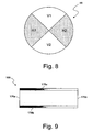
- correction of pupil ellipticities E ⁇ 1 may also be achieved by the filter 66. Since amplification of light rays is not possible, in this case it would in fact be necessary to attenuate only light rays which pass through the horizontal segments H1, H2. Since this cannot be achieved for all mask points during the scan process with only one transmission filter 66, in this case a pupil filter which is schematically shown in a plan view in Figure 8 , and is denoted by 88, may be fitted in a pupil plane of the illumination system 12, for example in the pupil plane 60 of the field diaphragm objective 56. This pupil filter 88 is likewise a transmission filter, but one in which only the two segments H1, H2 have a lower transmittance.
- the concomitant effect on the pupil ellipticity is equal for all field points and therefore also for all mask points.
- the effect achieved in this way is that the original pupil ellipticity E ⁇ 1 becomes a pupil ellipticity E > 1 for all mask points. This can be corrected in the manner described above by the transmission filter 66.
- the mask point 82 at the left-hand edge of the illuminated field 16 is again considered, then - if the second filter region were not present - this would receive a smaller radiation dose throughout the scan process than the mask point 86 in the symmetry plane 72.
- the reason for this is that for the mask point 86 in the symmetry plane 79, no rays are attenuated to a significant extent by the first filter regions 78a, 78b. Without the second filter region 80, the effect of this different attenuation for different mask points would be that the mask points in the embodiment shown would overall receive a commensurately smaller radiation dose, the father they are away from the symmetry plane 79. Such an effect is generally undesirable since, owing to the sharp exposure threshold of the photosensitive layer 22, the radiation dose has a crucial influence on the structure widths which are generated on the support 24.
- the second filter region 80 is therefore configured precisely so that the overall radiation dose during the scan process is equal for all mask points. At the mask points for which no or only little attenuation by the first filter regions 78a, 78b takes place, the attenuation by the second filter region 80 is greatest. At the edge of the illuminated field 16, where the greatest attenuation by the first filter regions 78a, 78b occurs, the second filter region 80 has its maximum transmittance of close to 100%.
- Figure 9 shows a second embodiment of a transmission filter, which is likewise suitable for use in the illumination system 12. Parts which are the same or correspond to one another are in this case denoted by reference numerals increased by 100.
- the first filter regions 178a, 178b do not have a mirror-symmetric distribution of the transmittance. Rather, in this embodiment the transmittance increases continuously from the left-hand side edge 176a to the right-hand side edge 176b. With such a distribution of the transmittance, for example, it is possible to correct a pupil ellipticity which continuously approximates the value 1 along this direction.
- the transmission filter 166 does not have a second filter region 80. Rather, the transmittance is maximal between the two first filter regions 178a, 178b.
- the section between the two first filter regions 178a, 178b may, for example, consist of a transparent homogeneous material or be entirely omitted. In the latter case, the transmission filter 166 therefore consists of two individual sub-elements which form the first filter regions 178a, 178b.
- Measures which may be envisaged for this are, for example, the use of a field diaphragm 54 as described for example in EP 0 952 491 A2 or EP 1 020 769 A2 .
- These known field diaphragms comprise a multiplicity of individual rod- or platelet-shaped diaphragm elements, which are displaceable individually and parallel to the scan direction.
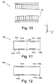
- Figure 10 shows a suitable field diaphragm 154 having an arrangement of diaphragm elements 90 in a schematic and highly simplified plan view.
- the diaphragm elements 90 make it possible to establish the width of the illuminated field 16 individually as a function of the longitudinal coordinate (X).
- the way in which the distribution of the transmittance is established in the first filter regions 178a, 178b depends above all on the dependency of the pupil ellipticity E on the x coordinate. Since the pupil ellipticity is generally a continuous, i.e. piecewise differentiable function of the x coordinate, the distribution of the transmittance in the first filter regions is also preferably continuous. Particularly when there are small pupil ellipticities to be corrected, however, it may be sufficient to provide first filter regions which have a discontinuous distribution of the transmittance.
- the transmission filter shown there and denoted overall by 266 comprises two first filter regions 278a, 278b, which are arranged at the upper and lower longitudinal edges 274a, 274b. Inside the first filter regions 278a, 278b, there are four filter zones 277a, 277b, 277c and 277d which are arranged mirror-symmetrically with respect to a symmetry plane 279 and inside which the transmittance is respectively constant.
- a transmission filter 266 for example, it is possible to correct wave-shaped pupil ellipticities which are symmetrical with respect to the symmetry plane 279.
- the stepped approximation to the wave-like profile of the pupil ellipticities leads to errors, these can be tolerated at least within certain limits.
- Undesired effects on the overall radiation dose can here again be avoided with the aid of the adjustable diaphragm elements 90, as shown in Figure 10 , or an additional second filter region is provided as in the transmission filter 66.
- the advantage of the transmission filter 266 over the embodiments described above is primarily that there are no regions with continuous profiles of the transmittance. The transmission filter 266 can therefore be produced particularly cost-effectively.
- Figure 12 shows another embodiment of a transmission filter denoted overall by 336.
- the transmission filter has first filter regions 378a, 378b, which likewise contain filter zones 377a, 377b with a constant transmittance over the surface.
- the filter zones 377a, 377b have an extent in the scan direction (Y) which depends on the x coordinate.
- the filter zones 377a, 377b have a step-shaped platform-like shape.
- the outer contours of the filter zones 377a, 377b which face one another may of course be contiguously curved as indicated on the right-hand half of Figure 12 by dashed lines 377a', 377b'.
- Figure 13 shows a transmission filter denoted by 466 according to another embodiment.
- the transmission filter 466 differs from the transmission filter 66 shown in Figure 6 in that two first filter regions 478a, 478b are respectively formed by mutually independent sub-elements which are displaceable in the scan direction (Y) with the aid of actuators 92.
- the distance between the first filter regions 478a, 478b can be increased or reduced symmetrically with respect to the illuminated field 16. In this way, for example, the effect on the pupil ellipticity can respectively be reduced or increased for all mask points.
- the constellation shown in Figure 14 is derived from the constellation shown in Figure 13 by displacing the two first filter regions 478a, 478b outwards, i.e. away from one another. This displacement is indicated by arrows 93 in Figure 13 . Owing to the concomitant increase in the distance between the first filter regions 478a, 478b, in the constellation shown in Figure 14 only a small portion of the light rays which pass through the vertical segments V1 and V2 are now attenuated by the first filter regions 478a and 478b, respectively. The effect on the pupil ellipticity is correspondingly small.
- first filter regions 478a, 478b By moving the first filter regions 478a, 478b along the scan direction Y, for example, it is therefore possible to accommodate changes in the pupil ellipticity, such as may occur in the course of the operating time of the illumination system 12, by adjusting the distance between the first filter regions 478a, 478b.
- Adjustable first filter regions 478a, 478b may however also be expedient when adaptation to different illumination settings is necessary. This will be explained with the aid of Figure 15 , which shows the transmission filter 466 in a constellation in which the distance between the first filter regions 478a, 478b is reduced relative to the constellation shown in Figure 13 . It is assumed here that a small conventional illumination setting has been selected, for which the maximum diameter of the light bundles 84', 86' at the position of the transmission filter 466 is less than in the constellation shown in Figure 13 .
- first filter regions 478a, 478b were to remain in the position shown in Figure 13 with such a small diameter of the light bundles 84', 86', then no light rays at all would pass through the first filter regions 478a, 478b.
- first filter regions 478a, 478b By displacing the first filter regions 478a, 478b in the direction indicated by arrows 93', however, light bundles in the segments V1 and V2 are again attenuated in the desired way by the first filter regions 478a and 478b, respectively.
- the entire transmission filter 66 may also be displaced parallel to the optical axis.
- the diameter of the light bundles passing through the transmission filter 66 is thereby changed, so that the effect of the first filter regions 78a, 78b is also changed.
- Z manipulators 98 may be used as indicated by dashes in Figure 2 . If only a few different illumination settings can be adjusted, then it is sufficient to arrange a plurality of exchange holders for receiving the transmission filter 66 along the optical axis OA. Discrete displacement of the transmission filter 66 along the optical axis OA is possible in this way, by transferring the transmission filter 66 from one exchange holder into another exchange holder.
- the transmission filter always has two first filter regions which can be delimited discontinuously from a second region (optionally, one which continuously is maximally transmissive) arranged between them. Nevertheless, the desired effect on the pupil ellipticity may also be achieved with transmission filters which have a continuous distribution of the transmittance over their entire surface.
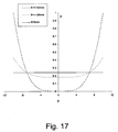
- FIG. 16 shows the distribution of the absorption coefficient A of such a transmission filter 566.
- those surfaces of the transmission filter 566 whose absorption coefficients lie within the ranges indicated in the legend are graphically separated from one another. In fact, however, the distribution of the absorption coefficient over the entire surface of the transmission filter 566 is continuous.
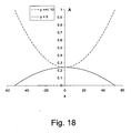
- the transmittance decreases with an increasing distance from the filter centre, as is shown most clearly in Figure 18 by the dashed line.
- a second filter region 580 which lies between the first filter regions 578a, 578b, the transmittance decreases towards the lateral filter edges.
- a filter function A(x,y) with a fourth-order polynomial is favourable because such filters can be produced as digital filters by tried and tested production methods.
- the function a(x) is established so that the pupil ellipticity E is corrected optimally.
- This function a(x) is preferably determined numerically, and it depends on the precise position of the transmission filter in the illumination system 12.
- the function b(x) therefore ensures that the overall radiation dose during the scan process remains equal at each mask point.
- illumination systems are set up so that they are telecentric on the mask side. This means that the centroid rays travel parallel to the optical axis OA in the mask plane 58. If an attenuation were to take place in only one of the segments, then this would entail tilting of the centroid rays so that the illumination system 12 would no longer be telecentric.
- an asymmetrisation may be achieved by moving the first filter regions 478a, 478b differently along the scan direction, so that an asymmetric arrangement is obtained with respect to the illuminated field 16.
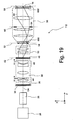
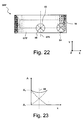
- Figure 19 is a meridional section through an illumination system, which is denoted in its entirety by 112, according to another embodiment. Since the illumination system 112 is similarly constructed as the illumination system 12 shown in Figure 2 , parts corresponding to one another are provided with the same reference numerals.
- the illumination system 112 differs from the illumination system 12 shown in Figure 2 mainly in that not just one but two transmission filters are arranged in the field diaphragm objective 56 in planes optically conjugate with one another.
- the second pupil plane 60 lies between the first transmission filter 666 and the second transmission filter 666'.
- the image resulting on the mask 14 is therefore point-symmetric with the original image in the intermediate field plane 52 , i.e. right and left as well as up and down interchanged.
- This can be seen for example from the principal ray denoted by 62, which comes from the intermediate field plane 52 in Figure 19 and initially travels below the optical axis OA.
- the principal ray 62 After passing through the second pupil plane 60, the principal ray 62 travels above the optical axis OA.
- the bundle of rays associated with the principal ray 62 is therefore inverted when it strikes the mask 14.
- the first and second transmission filters 666 and 666' shown in Figures 20 and 22 have only a first filter region, which is denoted respectively by 678 and 678'.
- the first filter regions 678, 678' in the embodiment represented have the same nonlinear distribution of the transmittance as the first filter regions 78a, 78b in the embodiment shown in Figure 6 .
- the transmittance therefore does not depend on the y coordinate, and it decreases with an increasing distance from a symmetry plane 679 which contains the optical axis. With such a distribution of the transmittance, it is possible to correct a pupil ellipticity as shown by way of example in Figure 5 .
- Figure 20 shows light bundles 84, 85 which converge respectively at mask points 82 and 86 in the mask plane 85.
- the constellation is in each case represented at the time when the illumination of the mask points 82 and 86 during the scan process begins.
- the light bundles 84, 85 pass through different positions on the transmission filters 666 and 666' at the same time. If the mask point 82 lying at the outer side edge of the illuminated field 16 is considered first, then the light bundle 84 which converges on the mask point 82 passes through the first transmission filter 666 in the upper left corner of the light field illuminated there, and it passes through the second transmission filter 666' in the bottom right corner of the light field illuminated there. This is a consequence of the aforementioned inversion at the second pupil plane 60.
- the way in which the various positions, at which the light bundle 84 passes through the two transmission filters 666, 666', has an effect on the pupil ellipticity will be made clear with the aid of the graphs shown in Figures 21 and 23 .
- the first transmission filter 666 the light bundle 84 experiences an absorption with absorption coefficients between A 2 and A 1 , as shown on the left in Figure 21 .
- the second transmission filter 666' the light bundle 84 experiences an absorption with absorption coefficients between A 1 and A 2 (see the right in Figure 21 ).
- the diameter of the light bundle 84 in the two filter planes is identical.
- the overall effect of the two transmission filters 666, 666' is therefore symmetrical for any light bundle which passes through the transmission filters 666, 666'.
- This is illustrated by the graph shown in Figure 23 , in which the absorption profiles in the two transmission filters 666, 666' are superimposed.
- the two differently dashed curves therein indicate the absorption which the light bundle experiences when it passes through the first transmission filter 666 and the second transmission filter 666', respectively.
- Superimposing the two absorption profiles leads to the curve represented by a solid line, which is symmetrical with respect to the line 99 represented by dots and dashes.
- the light bundle 84 will therefore be attenuated by the combination of the two transmission filters 666, 666' in the same way as if it were to pass through a single transmission filter which has the absorption distribution, symmetrical with respect to the line 99, shown by a solid line in Figure 23 .
- the effect of this absorption distribution, which is symmetrical for any light bundle, is that light rays which pass through the horizontal segments H1, H2 are attenuated more strongly than light rays which pass through the vertical segments V1, V2.
- the pupil ellipticity is therefore increased according to Eq. (1), so that the pupil ellipticity E can be brought close to the value 1 (optionally by using an additional transmission filter in a pupil plane). Owing to the symmetrical absorption distribution, moreover, the position of the principal ray as an energetically central ray (centroid ray) of the light bundle, and therefore the telecentric properties, are preserved at the same time.
- the corrective effect is also field-dependent in this embodiment, since the transmittance of the first filter regions 678, 678' varies nonlinearly along the X direction.
- the light bundle 85 assigned to the mask point 86 experiences for example only a minor correction of the pupil ellipticity, since the transmittance is modified only relatively weakly in the vicinity of the symmetry plane 679.
- the transmission filters 666, 666' have equal transmittance distributions, as can be seen Figures 20 to 22 . This is possible because the axial positions of the transmission filters 666, 666' are determined such that the diameters of the light bundles 84, 85 are identical on both filters 666, 666'.
- transmission filters 666, 666' are not desired or possible, these diameters will be different.
- one filter may be considered as a minified or magnified image (possibly inverted, if the filters are separated by n pupil planes and n+1 or n-1 field planes, wherein n is an odd integer).
- the scaling factor is determined by the difference of the diameter of a light bundle when it passes through the filters. Such a scaling ensures that the same conditions prevail for both light bundles even if their diameters on the filters are different.
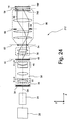
- Figure 24 is a meridional section through an illumination system of the projection exposure apparatus shown in Figure 1
- the illumination system which is denoted in its entirety by 212, is to a large extent similar to the illumination system 112 shown in Figure 19 , parts corresponding to one another are provided with the same reference numerals.
- the illumination system 212 also has a first and second transmission filter 766, 766' which are identical and contain only one filter region 778, as is shown in the top views of Figures 25 and 25 .
- the filters are not separated by the second pupil plane 60, but by the mask plane 58.
- the first transmission filter 766 is arranged between the second pupil plane 60 and the mask plane 58
- the second transmission filter 766' is arranged between the mask plane 58 and the projection objective 20 (not shown in Figure 24 ).
- the first transmission filter 766 is mounted inside a housing of the illumination system 212
- the second transmission filter 766' is mounted in the interspace between the illumination system 212 and the projection objective 20 (not shown in Figure 24 ).
- the second transmission filter 766' may be fixed to a frame that also accommodates the mask 14 so that it is moved by a mask stage during the projection operation.
- the second transmission filter 766' is received in a mounting frame that is fixedly (but preferably adjustably) attached with respect to the illumination system 212 and the projection objective 20 so that it cannot move during the projection operation.
- both the first and the second transmission filters are arranged in the interspace between the illumination system 212 and the projection objective 20.
- the separation by a field plane implies that there the corresponding positions on the first and second transmission filters 766, 766' are not point-symmetric images of one another, as is the case in the embodiment shown in Figure 19 . Instead, a light bundle that passes through the first transmission filter 766 through, say, the upper left corner passes through the second transmission filter 766' also through its upper left corner.
- the field plane nevertheless results in an "internal" inversion of each light bundle in the sense that rays propagating along one side on the bundle propagate on the opposite side of the bundle after they have passed through the mask plane 58.
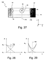
- the transmission filters 766, 766' have a transmission profile which is not symmetrical with respect to a plane 779 which contains the optical axis OA.
- it is possible to correct a pupil ellipticity which has not a symmetrical field dependency as shown in Figure 5 . It should be noted, however, that such a non-symmetrical profile could equally be used in the embodiment shown in Figure 19 .
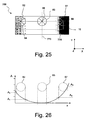
- Figure 25 shows light bundles 84, 85, 87 which converge respectively at mask points 82, 86, 89 in the mask plane 58.
- the constellation is in each case represented at the time when the illumination of the mask points 82 and 86 during the scan process begins.
- the light bundles 84, 85, 87 pass through identical portions on the transmission filters 766 and 766' at the same time.
- the mask point 82 lying at the outer side edge of the illuminated field 16 is considered first.
- the light bundle 84 which converges on the mask point 82 passes through the first transmission filter 766 in the upper left corner of the field illuminated on the transmission filter 766.
- the second transmission filter 766' the same applies, i.e. the light bundle passes through the upper left corner of the field illuminated on the transmission filter 766. This is a consequence of the aforementioned separation of the transmission filters 766, 766' by a field plane, namely the mask plane 56.
- the light bundle 84 will therefore be attenuated by the combination of the two transmission filters 766, 766' in the same way as if it were to pass through a single transmission filter which has the absorption distribution shown by a solid line in Figure 28 and being symmetrical with respect to the line 799.
- the effect of this absorption distribution, which is symmetrical for any light bundle, is that light rays which pass through the horizontal segments H1, H2 are attenuated more strongly than light rays which pass through the vertical segments V1, V2.
- the pupil ellipticity is therefore increased according to Eq. (1), so that the pupil ellipticity E can be brought close to the value 1 (optionally by using an additional transmission filter in a pupil plane). Owing to the symmetrical absorption distribution, moreover, the position of the principal ray as an energetically central ray (centroid ray) of the light bundle, and therefore the telecentric properties, are preserved at the same time.
- the corrective effect is also field-dependent in this embodiment, since the transmittance of the first filter regions 778, 778' varies along the X direction.
- the light bundle 85 assigned to the mask point 86 being situated on the line 779 experiences only a minor correction of the pupil ellipticity, since the transmittance is modified only relatively weakly in the vicinity of the plane 779.
- a light bundle 87 assigned to a mask point 81 at the upper right corner will be modified in a different way if compared with the light bundle 84. Since the absorption coefficient A of the transmission filters 766, 766' increases more rapidly with increasing +x values than for increasing -x values, the total transmission experienced by the bundle 87 when passing through both filter elements 766, 766' will also vary more strongly along the x direction. This is illustrated in Figure 29 which is a graph similar to what is shown in Figure 28 for the light bundle 84.
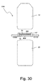
- FIG 30 is a schematic illustration of a projection exposure apparatus 810 according to still another embodiment which is, from a functional point of view, equivalent to the embodiment shown in Figure 24 .
- both transmission filters 866, 866' are arranged between the illumination system 12 and the projection objective 20.
- the transmission filters 866, 866' are attached to a frame 97 that also holds the mask 14 containing the structures 18.
- the transmission filters 866, 866' are arranged at equal distances from the structures 18 applied to the mask 14 so that the latter is sandwiched between the filters.
- a pellicle which is usually provided to protect the mask from dust and other environmental influences may be dispensed with.
- the arrangement of transmission filters 866, 866' outside the illumination system 12 and the projection objective 20 has the advantage that the transmission filters 866, 866' may be retrofitted in existing apparatus. Only the frame 97 holding the mask 14 needs to be modified such that it can also accommodate the two transmission filters 866, 866'.
Landscapes
- Physics & Mathematics (AREA)
- General Physics & Mathematics (AREA)
- Optics & Photonics (AREA)
- Exposure And Positioning Against Photoresist Photosensitive Materials (AREA)
- Exposure Of Semiconductors, Excluding Electron Or Ion Beam Exposure (AREA)
Abstract
Claims (15)
- Système d'éclairage d'un appareil d'exposition par projection pour microlithographie (10), dans lequel un masque (14) est déplacé le long d'une direction de balayage (Y) pendant une exposition d'une couche photosensible (22), comprenant :a) un plan pupillaire (42, 60),b) un plan de champ (52, 58),c) un filtre à transmission (66 ; 166 ; 266 ; 366 ; 466 ; 566 ; 666 ; 666' ; 766, 766'; 866, 866') qui a une transmittance différente au moins à deux positions,
dans lequeld) le filtre à transmission (66 ; 166 ; 266 ; 366 ; 466 ; 566 ; 666 ; 666' ; 766, 766' ; 866, 866') est disposé entre le plan pupillaire (42, 60) et le plan de champ (52, 58),e) un champ lumineux, qui a des dimensions plus courtes parallèlement à la direction de balayage (Y) que perpendiculairement à celle-ci, est éclairé sur le filtre à transmission (66 ; 166 ; 266 ; 366 ; 466 ; 566 ; 666 ; 666' ; 766, 766'; 866, 866') pendant l'exposition,caractérisé en ce que
le filtre à transmission (66 ; 166 ; 266 ; 366 ; 466 ; 566 ; 666 ; 666') est positionné à une distance du plan pupillaire (42, 60) et du plan de champ (52, 58) telle qu'un faisceau de rayons lumineux qui passent tous par un point dans le plan de champ passe à travers le filtre à transmission (66 ; 166 ; 266 ; 366 ; 466 ; 566 ; 666 ; 666' ; 766, 766' ; 866, 866') avec un diamètre maximum qui est inférieur à Lx/2 et supérieur à Ly/30, où Lx est la longueur du champ lumineux perpendiculairement à la direction de balayage (Y) et Ly est la longueur du champ lumineux le long de la direction de balayage (Y). - Système d'éclairage selon la revendication 1, comprenant un manipulateur (98) pour faire varier de manière continue la position du filtre à transmission (66 ; 166; 266 ; 366 ; 466 ; 566) le long de l'axe optique (OA).
- Système d'éclairage selon une des revendications précédentes, dans lequel le plan de champ est un plan de masque (58) dans lequel le masque (14) est déplacé pendant l'exposition.
- Système d'éclairage selon une des revendications précédentes, dans lequel le filtre à transmission (66 ; 166 ; 266 ; 366 ; 466 ; 566 ; 666 ; 666' ; 766, 766' ; 866, 866') comprend au moins une première région de filtre (78a, 78b ; 178a, 178b ; 278a, 278b ; 378a, 378b ; 378a', 378b' ; 478a, 478b ; 578a, 578b ; 678 ; 678') qui a une transmittance qui varie perpendiculairement à la direction de balayage (Y).
- Système d'éclairage selon la revendication 4, dans lequel la transmittance de la première région de filtre (78a, 78b ; 178a, 178b ; 278a, 278b ; 378a, 378b ; 378a', 378b' ; 478a, 478b ; 678 ; 678' ; 778) est constante parallèlement à la direction de balayage (Y).
- Système d'éclairage selon une des revendications 4 à 5, dans lequel la transmittance dans la première région de filtre (78a, 78b ; 278a, 278b ; 378a, 378b ; 378a', 378b' ; 478a, 478b ; 578a, 578b ; 678 ; 678') a une distribution spatiale qui est symétrique en miroir par rapport à un plan de symétrie (79 ; 279, 679) qui s'étend parallèlement à la direction de balayage (Y) et contient un axe optique (OA) du système d'éclairage (12).
- Système d'éclairage selon une des revendications 4 à 6, dans lequel le filtre à transmission comprend une seconde région de filtre (80 ; 580) qui a une distribution spatiale de la transmittance perpendiculairement à la direction de balayage (Y) qui est qualitativement opposée à la distribution spatiale de la transmittance de la première région de filtre (78a, 78b ; 478a, 478b ; 578a, 578b).
- Système d'éclairage selon une des revendications 4 à 7, dans lequel la première région de filtre (478a, 478b) est conçue comme un sous-élément qui est déplaçable par rapport au champ lumineux dans la direction de balayage (Y).
- Système d'éclairage selon une des revendications 4 à 8, dans lequel le filtre à transmission comprend deux premières régions de filtre (78a, 78b ; 178a, 178b; 278a, 278b ; 378a, 378b ; 378a', 378b' ; 478a, 478b ; 578a, 578b) dont chacune a une transmittance qui varie perpendiculairement à la direction de balayage (Y).
- Système d'éclairage selon la revendication 9, dans lequel les deux premières régions de filtre (478a, 478b) sont conçues comme des sous-éléments qui sont déplaçables par rapport au champ lumineux le long de la direction de balayage (Y).
- Système d'éclairage selon une des revendications 1 à 3, dans lequel le système d'éclairage a deux filtres à transmission (666, 666') avec des distributions spatiales de la transmittance qui sont symétriques en miroir par rapport à un axe de symétrie (679) qui s'étend parallèlement à la direction de balayage (Y), et dans lequel les filtres à transmission sont séparés l'un de l'autre par un nombre impair de plans pupillaires (42, 60).
- Système d'éclairage selon la revendication 11, dans lequel les deux filtres à transmission (666, 666') sont disposés dans des plans qui sont optiquement conjugués l'un de l'autre.
- Système d'éclairage selon la revendication 11 ou 12, dans lequel la transmittance des deux filtres à transmission (666, 666') varie perpendiculairement à la direction de balayage (Y), et dans lequel la transmittance des deux filtres à transmission (666, 666') est constante parallèlement à la direction de balayage (Y).
- Système d'éclairage selon une des revendications 11 à 13, dans lequel les deux filtres à transmission (666, 666') ont la même distribution spatiale de la transmittance.
- Système d'éclairage selon une des revendications précédentes, dans lequel le filtre à transmission a une première région de filtre (78a, 78b ; 278a, 278b ; 478a, 478b ; 578a, 578b ; 678 ; 678') à l'intérieur de laquelle la transmittance est symétrique en miroir par rapport à un plan de symétrie (79, 579) qui s'étend parallèlement à la direction de balayage (Y) et qui contient l'axe optique (OA) du système d'éclairage (12).
Applications Claiming Priority (2)
| Application Number | Priority Date | Filing Date | Title |
|---|---|---|---|
| US88718607P | 2007-01-30 | 2007-01-30 | |
| PCT/EP2008/000706 WO2008092653A2 (fr) | 2007-01-30 | 2008-01-30 | Système d'éclairage d'un appareil d'exposition par projection pour microlithographie |
Publications (2)
| Publication Number | Publication Date |
|---|---|
| EP2126636A2 EP2126636A2 (fr) | 2009-12-02 |
| EP2126636B1 true EP2126636B1 (fr) | 2012-06-13 |
Family
ID=39672917
Family Applications (1)
| Application Number | Title | Priority Date | Filing Date |
|---|---|---|---|
| EP08715667A Not-in-force EP2126636B1 (fr) | 2007-01-30 | 2008-01-30 | Système d'éclairage d'un appareil d'exposition par projection pour microlithographie |
Country Status (6)
| Country | Link |
|---|---|
| US (2) | US8169594B2 (fr) |
| EP (1) | EP2126636B1 (fr) |
| JP (1) | JP2010517310A (fr) |
| KR (1) | KR101440652B1 (fr) |
| CN (1) | CN101636695B (fr) |
| WO (1) | WO2008092653A2 (fr) |
Families Citing this family (19)
| Publication number | Priority date | Publication date | Assignee | Title |
|---|---|---|---|---|
| JP4599936B2 (ja) | 2004-08-17 | 2010-12-15 | 株式会社ニコン | 照明光学装置、照明光学装置の調整方法、露光装置、および露光方法 |
| KR100865554B1 (ko) * | 2007-06-27 | 2008-10-29 | 주식회사 하이닉스반도체 | 노광 장치 |
| US8908151B2 (en) | 2008-02-14 | 2014-12-09 | Nikon Corporation | Illumination optical system, exposure apparatus, device manufacturing method, compensation filter, and exposure optical system |
| DE102008011501A1 (de) | 2008-02-25 | 2009-08-27 | Carl Zeiss Smt Ag | Verfahren zum Betreiben eines Beleuchtungssystems einer mikrolithographischen Projektionsbelichtungsanlage |
| JP5201061B2 (ja) * | 2008-04-29 | 2013-06-05 | 株式会社ニコン | 補正フィルター、照明光学系、露光装置、およびデバイス製造方法 |
| US8237684B2 (en) * | 2008-09-26 | 2012-08-07 | Avago Technologies Ecbu Ip (Singapore) Pte. Ltd. | User input device with planar light guide illumination plate |
| KR101708948B1 (ko) * | 2008-12-24 | 2017-03-08 | 가부시키가이샤 니콘 | 조명 광학계, 노광 장치 및 디바이스의 제조 방법 |
| JP5187632B2 (ja) * | 2008-12-30 | 2013-04-24 | 株式会社ニコン | 補正ユニット、照明光学系、露光装置、およびデバイス製造方法 |
| JP5187631B2 (ja) * | 2008-12-30 | 2013-04-24 | 株式会社ニコン | 補正ユニット、照明光学系、露光装置、およびデバイス製造方法 |
| JP5473350B2 (ja) * | 2009-02-13 | 2014-04-16 | キヤノン株式会社 | 照明光学系、露光装置及びデバイスの製造方法 |
| DE102012219806A1 (de) * | 2012-10-30 | 2014-04-30 | Carl Zeiss Smt Gmbh | Projektionsbelichtungsanlage mit mindestens einem Mittel zur Reduktion des Einflusses von Druckschwankungen |
| DE102013206528B4 (de) | 2013-04-12 | 2014-11-20 | Carl Zeiss Smt Gmbh | Mikrolithographische projektionsbelichtungsanlage mit einem variablen transmissionsfilter |
| DE102013208129B4 (de) | 2013-05-03 | 2014-11-20 | Carl Zeiss Smt Gmbh | Mikrolithographische Projektionsbelichtungsanlage mit einem variablen Transmissionsfilter |
| CN103293877B (zh) * | 2013-05-31 | 2014-12-31 | 上海华力微电子有限公司 | 采用四极曝光方式的光刻装置、通光单元及光刻方法 |
| GB2540654A (en) * | 2015-05-13 | 2017-01-25 | Zeiss Carl Smt Gmbh | Method of variably attenuating a beam of projection light in an optical system of a microlithographic apparatus |
| WO2018029962A1 (fr) | 2016-08-08 | 2018-02-15 | ソニー株式会社 | Dispositif d'endoscope et procédé de commande de dispositif d'endoscope |
| JP6803483B2 (ja) | 2017-06-19 | 2020-12-23 | ズース マイクロテック フォトニック システムズ インコーポレイテッド | 光学系における倍率補正及び/又はビームステアリング |
| US11175487B2 (en) | 2017-06-19 | 2021-11-16 | Suss Microtec Photonic Systems Inc. | Optical distortion reduction in projection systems |
| JP7413234B2 (ja) * | 2020-11-06 | 2024-01-15 | 株式会社東芝 | 光学撮像装置、光学検査装置、および、光学検査方法 |
Family Cites Families (25)
| Publication number | Priority date | Publication date | Assignee | Title |
|---|---|---|---|---|
| JP3301153B2 (ja) * | 1993-04-06 | 2002-07-15 | 株式会社ニコン | 投影露光装置、露光方法、及び素子製造方法 |
| JPH09199390A (ja) * | 1996-01-16 | 1997-07-31 | Hitachi Ltd | パターン形成方法、投影露光装置および半導体装置の製造方法 |
| US7130129B2 (en) | 1996-12-21 | 2006-10-31 | Carl Zeiss Smt Ag | Reticle-masking objective with aspherical lenses |
| JPH11176746A (ja) * | 1997-10-07 | 1999-07-02 | Nikon Corp | 走査型露光方法、装置及び素子製造方法 |
| US6013401A (en) | 1997-03-31 | 2000-01-11 | Svg Lithography Systems, Inc. | Method of controlling illumination field to reduce line width variation |
| EP0952491A3 (fr) | 1998-04-21 | 2001-05-09 | Asm Lithography B.V. | Appareil lithographique |
| JP4545854B2 (ja) * | 1999-11-05 | 2010-09-15 | キヤノン株式会社 | 投影露光装置 |
| DE10043315C1 (de) * | 2000-09-02 | 2002-06-20 | Zeiss Carl | Projektionsbelichtungsanlage |
| DE10046218B4 (de) * | 2000-09-19 | 2007-02-22 | Carl Zeiss Smt Ag | Projektionsbelichtungsanlage |
| DE10065198A1 (de) * | 2000-12-20 | 2002-07-11 | Zeiss Carl | Lichtintegrator für eine Beleuchtungseinrichtung |
| WO2003023832A1 (fr) * | 2001-09-07 | 2003-03-20 | Nikon Corporation | Procede et systeme d'exposition, et procede de construction de dispositif associe |
| JP4923370B2 (ja) * | 2001-09-18 | 2012-04-25 | 株式会社ニコン | 照明光学系、露光装置、及びマイクロデバイスの製造方法 |
| DE10158921A1 (de) * | 2001-11-30 | 2003-06-26 | Zeiss Carl Smt Ag | Verfahren zum Bestimmen von mindestens einer Kenngröße, die für die Beleuchtungswinkelverteilung einer der Beleuchtung eines Gegenstandes dienenden Lichtquelle einer Projektionsbelichtungsanlage charakteristisch ist |
| WO2005006079A1 (fr) | 2003-07-07 | 2005-01-20 | Carl Zeiss Smt Ag | Dispositif d'eclairage d'une installation d'eclairage de projection microlithographique |
| KR100598095B1 (ko) * | 2003-07-10 | 2006-07-07 | 삼성전자주식회사 | 노광 장치 |
| WO2005015310A2 (fr) | 2003-07-16 | 2005-02-17 | Carl Zeiss Smt Ag | Systeme d'eclairage pour un appareil d'exposition par projection microlithographique |
| US7030958B2 (en) * | 2003-12-31 | 2006-04-18 | Asml Netherlands B.V. | Optical attenuator device, radiation system and lithographic apparatus therewith and device manufacturing method |
| DE102004011733A1 (de) * | 2004-03-04 | 2005-09-22 | Carl Zeiss Smt Ag | Transmissionsfiltervorrichtung |
| EP1759248A1 (fr) * | 2004-06-04 | 2007-03-07 | Carl Zeiss SMT AG | Systeme de projection avec compensation des variations d'intensite et element de compensation pour ce systeme |
| US7283209B2 (en) * | 2004-07-09 | 2007-10-16 | Carl Zeiss Smt Ag | Illumination system for microlithography |
| JP4599936B2 (ja) | 2004-08-17 | 2010-12-15 | 株式会社ニコン | 照明光学装置、照明光学装置の調整方法、露光装置、および露光方法 |
| JP2006066429A (ja) * | 2004-08-24 | 2006-03-09 | Nikon Corp | 照明光学装置、露光装置、および露光方法 |
| DE102004063314A1 (de) * | 2004-12-23 | 2006-07-13 | Carl Zeiss Smt Ag | Filtereinrichtung für die Kompensation einer asymmetrischen Pupillenausleuchtung |
| JP5030944B2 (ja) | 2005-04-26 | 2012-09-19 | カール・ツァイス・エスエムティー・ゲーエムベーハー | マイクロリソグラフィ露光装置のための照明システム |
| DE102006013459A1 (de) * | 2006-03-23 | 2007-09-27 | Infineon Technologies Ag | Anordnung zur Übertragung von Strukturelementen einer Photomaske auf ein Substrat und Verfahren zur Übertragung von Strukturelementen einer Photomaske auf ein Substrat |
-
2008
- 2008-01-30 KR KR1020097017904A patent/KR101440652B1/ko active IP Right Grant
- 2008-01-30 EP EP08715667A patent/EP2126636B1/fr not_active Not-in-force
- 2008-01-30 WO PCT/EP2008/000706 patent/WO2008092653A2/fr active Application Filing
- 2008-01-30 JP JP2009547594A patent/JP2010517310A/ja active Pending
- 2008-01-30 CN CN2008800035249A patent/CN101636695B/zh not_active Expired - Fee Related
-
2009
- 2009-07-27 US US12/509,738 patent/US8169594B2/en active Active
-
2012
- 2012-04-03 US US13/438,179 patent/US9116441B2/en not_active Expired - Fee Related
Also Published As
| Publication number | Publication date |
|---|---|
| CN101636695A (zh) | 2010-01-27 |
| CN101636695B (zh) | 2012-06-06 |
| KR101440652B1 (ko) | 2014-09-22 |
| US8169594B2 (en) | 2012-05-01 |
| EP2126636A2 (fr) | 2009-12-02 |
| US20090323043A1 (en) | 2009-12-31 |
| WO2008092653A3 (fr) | 2008-10-09 |
| US9116441B2 (en) | 2015-08-25 |
| US20120188527A1 (en) | 2012-07-26 |
| WO2008092653A2 (fr) | 2008-08-07 |
| KR20090129409A (ko) | 2009-12-16 |
| JP2010517310A (ja) | 2010-05-20 |
Similar Documents
| Publication | Publication Date | Title |
|---|---|---|
| EP2126636B1 (fr) | Système d'éclairage d'un appareil d'exposition par projection pour microlithographie | |
| US9910359B2 (en) | Illumination system of a microlithographic projection exposure apparatus | |
| JP4489783B2 (ja) | リソグラフィ投影装置およびデバイス製造方法 | |
| JP6407193B2 (ja) | 投影露光方法、投影露光システム、及び投影対物系 | |
| US8873151B2 (en) | Illumination system for a microlithgraphic exposure apparatus | |
| EP2198344B1 (fr) | Appareil d'exposition par projection microlithographique | |
| US9665010B2 (en) | Method for operating a microlithographic projection exposure apparatus | |
| WO2016184560A1 (fr) | Procédé de fonctionnement d'appareil de projection microlitographique | |
| US6738128B2 (en) | Exposure apparatus | |
| KR20170114976A (ko) | 투영 노광 방법 및 투영 노광 장치 | |
| JPWO2010073795A1 (ja) | 照明光学系、露光装置及びデバイスの製造方法 | |
| EP1522893A2 (fr) | Système d'illumination optique et appareil d'exposition le comprenant | |
| WO2014117791A1 (fr) | Appareil d'exposition par projection microlithographique et son procédé de fonctionnement | |
| TWI444779B (zh) | 微影蝕刻的投影曝光儀器之照明系統 | |
| US8300211B2 (en) | Catadioptric projection objective | |
| JP5453804B2 (ja) | 照明光学系、露光装置及びデバイスの製造方法 | |
| WO2012123000A1 (fr) | Procédé pour faire fonctionner un appareil d'exposition à projection microlithographique | |
| WO2012116710A1 (fr) | Système d'éclairage d'un appareil d'exposition à projection microlithographique |
Legal Events
| Date | Code | Title | Description |
|---|---|---|---|
| PUAI | Public reference made under article 153(3) epc to a published international application that has entered the european phase |
Free format text: ORIGINAL CODE: 0009012 |
|
| 17P | Request for examination filed |
Effective date: 20090811 |
|
| AK | Designated contracting states |
Kind code of ref document: A2 Designated state(s): AT BE BG CH CY CZ DE DK EE ES FI FR GB GR HR HU IE IS IT LI LT LU LV MC MT NL NO PL PT RO SE SI SK TR |
|
| DAX | Request for extension of the european patent (deleted) | ||
| RAP1 | Party data changed (applicant data changed or rights of an application transferred) |
Owner name: CARL ZEISS SMT GMBH |
|
| GRAP | Despatch of communication of intention to grant a patent |
Free format text: ORIGINAL CODE: EPIDOSNIGR1 |
|
| GRAS | Grant fee paid |
Free format text: ORIGINAL CODE: EPIDOSNIGR3 |
|
| GRAA | (expected) grant |
Free format text: ORIGINAL CODE: 0009210 |
|
| AK | Designated contracting states |
Kind code of ref document: B1 Designated state(s): AT BE BG CH CY CZ DE DK EE ES FI FR GB GR HR HU IE IS IT LI LT LU LV MC MT NL NO PL PT RO SE SI SK TR |
|
| REG | Reference to a national code |
Ref country code: GB Ref legal event code: FG4D |
|
| REG | Reference to a national code |
Ref country code: AT Ref legal event code: REF Ref document number: 562245 Country of ref document: AT Kind code of ref document: T Effective date: 20120615 Ref country code: CH Ref legal event code: EP |
|
| REG | Reference to a national code |
Ref country code: IE Ref legal event code: FG4D |
|
| REG | Reference to a national code |
Ref country code: NL Ref legal event code: T3 |
|
| REG | Reference to a national code |
Ref country code: DE Ref legal event code: R096 Ref document number: 602008016300 Country of ref document: DE Effective date: 20120809 |
|
| PG25 | Lapsed in a contracting state [announced via postgrant information from national office to epo] |
Ref country code: LT Free format text: LAPSE BECAUSE OF FAILURE TO SUBMIT A TRANSLATION OF THE DESCRIPTION OR TO PAY THE FEE WITHIN THE PRESCRIBED TIME-LIMIT Effective date: 20120613 Ref country code: NO Free format text: LAPSE BECAUSE OF FAILURE TO SUBMIT A TRANSLATION OF THE DESCRIPTION OR TO PAY THE FEE WITHIN THE PRESCRIBED TIME-LIMIT Effective date: 20120913 Ref country code: CY Free format text: LAPSE BECAUSE OF FAILURE TO SUBMIT A TRANSLATION OF THE DESCRIPTION OR TO PAY THE FEE WITHIN THE PRESCRIBED TIME-LIMIT Effective date: 20120613 Ref country code: SE Free format text: LAPSE BECAUSE OF FAILURE TO SUBMIT A TRANSLATION OF THE DESCRIPTION OR TO PAY THE FEE WITHIN THE PRESCRIBED TIME-LIMIT Effective date: 20120613 Ref country code: FI Free format text: LAPSE BECAUSE OF FAILURE TO SUBMIT A TRANSLATION OF THE DESCRIPTION OR TO PAY THE FEE WITHIN THE PRESCRIBED TIME-LIMIT Effective date: 20120613 |
|
| REG | Reference to a national code |
Ref country code: AT Ref legal event code: MK05 Ref document number: 562245 Country of ref document: AT Kind code of ref document: T Effective date: 20120613 |
|
| REG | Reference to a national code |
Ref country code: LT Ref legal event code: MG4D Effective date: 20120613 |
|
| PG25 | Lapsed in a contracting state [announced via postgrant information from national office to epo] |
Ref country code: SI Free format text: LAPSE BECAUSE OF FAILURE TO SUBMIT A TRANSLATION OF THE DESCRIPTION OR TO PAY THE FEE WITHIN THE PRESCRIBED TIME-LIMIT Effective date: 20120613 Ref country code: GR Free format text: LAPSE BECAUSE OF FAILURE TO SUBMIT A TRANSLATION OF THE DESCRIPTION OR TO PAY THE FEE WITHIN THE PRESCRIBED TIME-LIMIT Effective date: 20120914 Ref country code: HR Free format text: LAPSE BECAUSE OF FAILURE TO SUBMIT A TRANSLATION OF THE DESCRIPTION OR TO PAY THE FEE WITHIN THE PRESCRIBED TIME-LIMIT Effective date: 20120613 Ref country code: LV Free format text: LAPSE BECAUSE OF FAILURE TO SUBMIT A TRANSLATION OF THE DESCRIPTION OR TO PAY THE FEE WITHIN THE PRESCRIBED TIME-LIMIT Effective date: 20120613 |
|
| PG25 | Lapsed in a contracting state [announced via postgrant information from national office to epo] |
Ref country code: AT Free format text: LAPSE BECAUSE OF FAILURE TO SUBMIT A TRANSLATION OF THE DESCRIPTION OR TO PAY THE FEE WITHIN THE PRESCRIBED TIME-LIMIT Effective date: 20120613 Ref country code: CZ Free format text: LAPSE BECAUSE OF FAILURE TO SUBMIT A TRANSLATION OF THE DESCRIPTION OR TO PAY THE FEE WITHIN THE PRESCRIBED TIME-LIMIT Effective date: 20120613 Ref country code: SK Free format text: LAPSE BECAUSE OF FAILURE TO SUBMIT A TRANSLATION OF THE DESCRIPTION OR TO PAY THE FEE WITHIN THE PRESCRIBED TIME-LIMIT Effective date: 20120613 Ref country code: BE Free format text: LAPSE BECAUSE OF FAILURE TO SUBMIT A TRANSLATION OF THE DESCRIPTION OR TO PAY THE FEE WITHIN THE PRESCRIBED TIME-LIMIT Effective date: 20120613 Ref country code: RO Free format text: LAPSE BECAUSE OF FAILURE TO SUBMIT A TRANSLATION OF THE DESCRIPTION OR TO PAY THE FEE WITHIN THE PRESCRIBED TIME-LIMIT Effective date: 20120613 Ref country code: IS Free format text: LAPSE BECAUSE OF FAILURE TO SUBMIT A TRANSLATION OF THE DESCRIPTION OR TO PAY THE FEE WITHIN THE PRESCRIBED TIME-LIMIT Effective date: 20121013 Ref country code: EE Free format text: LAPSE BECAUSE OF FAILURE TO SUBMIT A TRANSLATION OF THE DESCRIPTION OR TO PAY THE FEE WITHIN THE PRESCRIBED TIME-LIMIT Effective date: 20120613 |
|
| PG25 | Lapsed in a contracting state [announced via postgrant information from national office to epo] |
Ref country code: PL Free format text: LAPSE BECAUSE OF FAILURE TO SUBMIT A TRANSLATION OF THE DESCRIPTION OR TO PAY THE FEE WITHIN THE PRESCRIBED TIME-LIMIT Effective date: 20120613 Ref country code: IT Free format text: LAPSE BECAUSE OF FAILURE TO SUBMIT A TRANSLATION OF THE DESCRIPTION OR TO PAY THE FEE WITHIN THE PRESCRIBED TIME-LIMIT Effective date: 20120613 Ref country code: PT Free format text: LAPSE BECAUSE OF FAILURE TO SUBMIT A TRANSLATION OF THE DESCRIPTION OR TO PAY THE FEE WITHIN THE PRESCRIBED TIME-LIMIT Effective date: 20121015 |
|
| PLBE | No opposition filed within time limit |
Free format text: ORIGINAL CODE: 0009261 |
|
| STAA | Information on the status of an ep patent application or granted ep patent |
Free format text: STATUS: NO OPPOSITION FILED WITHIN TIME LIMIT |
|
| PG25 | Lapsed in a contracting state [announced via postgrant information from national office to epo] |
Ref country code: DK Free format text: LAPSE BECAUSE OF FAILURE TO SUBMIT A TRANSLATION OF THE DESCRIPTION OR TO PAY THE FEE WITHIN THE PRESCRIBED TIME-LIMIT Effective date: 20120613 Ref country code: ES Free format text: LAPSE BECAUSE OF FAILURE TO SUBMIT A TRANSLATION OF THE DESCRIPTION OR TO PAY THE FEE WITHIN THE PRESCRIBED TIME-LIMIT Effective date: 20120924 |
|
| 26N | No opposition filed |
Effective date: 20130314 |
|
| REG | Reference to a national code |
Ref country code: DE Ref legal event code: R097 Ref document number: 602008016300 Country of ref document: DE Effective date: 20130314 |
|
| PG25 | Lapsed in a contracting state [announced via postgrant information from national office to epo] |
Ref country code: BG Free format text: LAPSE BECAUSE OF FAILURE TO SUBMIT A TRANSLATION OF THE DESCRIPTION OR TO PAY THE FEE WITHIN THE PRESCRIBED TIME-LIMIT Effective date: 20120913 |
|
| PG25 | Lapsed in a contracting state [announced via postgrant information from national office to epo] |
Ref country code: MC Free format text: LAPSE BECAUSE OF NON-PAYMENT OF DUE FEES Effective date: 20130131 |
|
| REG | Reference to a national code |
Ref country code: CH Ref legal event code: PL |
|
| GBPC | Gb: european patent ceased through non-payment of renewal fee |
Effective date: 20130130 |
|
| REG | Reference to a national code |
Ref country code: IE Ref legal event code: MM4A |
|
| PG25 | Lapsed in a contracting state [announced via postgrant information from national office to epo] |
Ref country code: CH Free format text: LAPSE BECAUSE OF NON-PAYMENT OF DUE FEES Effective date: 20130131 Ref country code: LI Free format text: LAPSE BECAUSE OF NON-PAYMENT OF DUE FEES Effective date: 20130131 |
|
| PG25 | Lapsed in a contracting state [announced via postgrant information from national office to epo] |
Ref country code: GB Free format text: LAPSE BECAUSE OF NON-PAYMENT OF DUE FEES Effective date: 20130130 |
|
| PG25 | Lapsed in a contracting state [announced via postgrant information from national office to epo] |
Ref country code: IE Free format text: LAPSE BECAUSE OF NON-PAYMENT OF DUE FEES Effective date: 20130130 |
|
| PG25 | Lapsed in a contracting state [announced via postgrant information from national office to epo] |
Ref country code: MT Free format text: LAPSE BECAUSE OF FAILURE TO SUBMIT A TRANSLATION OF THE DESCRIPTION OR TO PAY THE FEE WITHIN THE PRESCRIBED TIME-LIMIT Effective date: 20120613 |
|
| PG25 | Lapsed in a contracting state [announced via postgrant information from national office to epo] |
Ref country code: TR Free format text: LAPSE BECAUSE OF FAILURE TO SUBMIT A TRANSLATION OF THE DESCRIPTION OR TO PAY THE FEE WITHIN THE PRESCRIBED TIME-LIMIT Effective date: 20120613 |
|
| PG25 | Lapsed in a contracting state [announced via postgrant information from national office to epo] |
Ref country code: HU Free format text: LAPSE BECAUSE OF FAILURE TO SUBMIT A TRANSLATION OF THE DESCRIPTION OR TO PAY THE FEE WITHIN THE PRESCRIBED TIME-LIMIT; INVALID AB INITIO Effective date: 20080130 Ref country code: LU Free format text: LAPSE BECAUSE OF NON-PAYMENT OF DUE FEES Effective date: 20130130 |
|
| REG | Reference to a national code |
Ref country code: FR Ref legal event code: PLFP Year of fee payment: 9 |
|
| REG | Reference to a national code |
Ref country code: FR Ref legal event code: PLFP Year of fee payment: 10 |
|
| PGFP | Annual fee paid to national office [announced via postgrant information from national office to epo] |
Ref country code: NL Payment date: 20170119 Year of fee payment: 10 |
|
| PGFP | Annual fee paid to national office [announced via postgrant information from national office to epo] |
Ref country code: FR Payment date: 20170120 Year of fee payment: 10 Ref country code: DE Payment date: 20170120 Year of fee payment: 10 |
|
| REG | Reference to a national code |
Ref country code: DE Ref legal event code: R119 Ref document number: 602008016300 Country of ref document: DE |
|
| REG | Reference to a national code |
Ref country code: NL Ref legal event code: MM Effective date: 20180201 |
|
| PG25 | Lapsed in a contracting state [announced via postgrant information from national office to epo] |
Ref country code: FR Free format text: LAPSE BECAUSE OF NON-PAYMENT OF DUE FEES Effective date: 20180131 Ref country code: DE Free format text: LAPSE BECAUSE OF NON-PAYMENT OF DUE FEES Effective date: 20180801 |
|
| REG | Reference to a national code |
Ref country code: FR Ref legal event code: ST Effective date: 20180928 |
|
| PG25 | Lapsed in a contracting state [announced via postgrant information from national office to epo] |
Ref country code: NL Free format text: LAPSE BECAUSE OF NON-PAYMENT OF DUE FEES Effective date: 20180201 |