EP2123204A2 - Vorrichtung zur Regulierung des Saugluftstroms eines Saugers - Google Patents
Vorrichtung zur Regulierung des Saugluftstroms eines Saugers Download PDFInfo
- Publication number
- EP2123204A2 EP2123204A2 EP20090004933 EP09004933A EP2123204A2 EP 2123204 A2 EP2123204 A2 EP 2123204A2 EP 20090004933 EP20090004933 EP 20090004933 EP 09004933 A EP09004933 A EP 09004933A EP 2123204 A2 EP2123204 A2 EP 2123204A2
- Authority
- EP
- European Patent Office
- Prior art keywords
- suction
- false air
- opening
- false
- air
- Prior art date
- Legal status (The legal status is an assumption and is not a legal conclusion. Google has not performed a legal analysis and makes no representation as to the accuracy of the status listed.)
- Granted
Links
Images

Classifications
-
- A—HUMAN NECESSITIES
- A47—FURNITURE; DOMESTIC ARTICLES OR APPLIANCES; COFFEE MILLS; SPICE MILLS; SUCTION CLEANERS IN GENERAL
- A47L—DOMESTIC WASHING OR CLEANING; SUCTION CLEANERS IN GENERAL
- A47L9/00—Details or accessories of suction cleaners, e.g. mechanical means for controlling the suction or for effecting pulsating action; Storing devices specially adapted to suction cleaners or parts thereof; Carrying-vehicles specially adapted for suction cleaners
- A47L9/0072—Mechanical means for controlling the suction or for effecting pulsating action
Definitions
- the present invention relates to a device for regulating the suction air flow of a nipple by means of false air.
- a sucker usually comprises a suction nozzle, a suction channel and a suction device.
- the suction air flow enters the suction channel through the suction nozzle and continues to flow into the suction device.
- the suction air flow is passed through a filter device, so that dust and dirt are collected in a collecting container provided in the suction device.
- a different strong suction air flow is required for different surfaces to be cleaned (parquet, carpets, furniture, etc.) a different strong suction air flow is required. It should be avoided that the suction nozzle is stuck to the surface to be cleaned and that sensitive surfaces are damaged.
- the DE 10 2005 010 983 B3 describes an air flow regulator in the suction channel of a vacuum cleaner whose noise is reduced because the false air is supplied parallel to the flow direction of the suction air.
- the suction channel in an extension section to false air openings which by means of a suction channel surrounding the rotatable sleeve steplessly can be opened and closed.
- this solution is structurally complex and therefore associated with comparatively high production costs.
- the DE 1 879 398 U suggests, however, to arrange the air flow regulator in the suction nozzle itself.
- the air flow regulator is designed as a continuously adjustable slide, which is associated with a provided in the bottom of the suction nozzle opening through which the false air enters the suction nozzle.
- this solution has the disadvantage that the air flow regulator when changing the suction nozzle (eg. From a carpet nozzle to a furniture nozzle) is lost and can not be realized constructively in all suction nozzles.
- the object of the present invention is therefore to provide a device for regulating the suction air flow of a nipple, which is structurally simple and allows the regulation of the suction air flow with the lowest possible additional noise.
- a suction device for the sucker having at least one false air opening, the opening cross-section is controlled by a control such that false air is supplied to the suction air stream.
- the suction air flow is regulated neither in the suction nozzle nor in the suction channel, but by means of a false air opening arranged in the suction device.
- the noise associated with the intake of false air is effectively damped by the housing of the suction device.
- the suction device in contrast to the suction channel, is located at some distance from the cleaner cleaning power, which further reduces the noise load.
- the device of the invention operates purely mechanically, is structurally simple and can thus be realized inexpensively. Existing suction devices can be retrofitted.
- the control can be configured as desired, with a configuration as a slider or thumbwheel is particularly useful. It is also advantageous if the opening cross section of the false air opening by means of the control element is steplessly controlled to allow optimum adaptation to the surface to be cleaned.
- the device according to the invention can be realized with suction devices of all kinds.
- Conventional suction devices have a lower part designed as a collecting container and an upper part, even if theoretically a device according to the invention with a one-piece suction device is conceivable.
- the fan motor can be arranged in any part of the housing (eg. In the upper part or in the lower part).
- the false air opening may be provided in the upper part, so that a flow connection between 0berteil and lower part is formed. Since the inlet nozzle for the suction channel is arranged on the lower part designed as a collecting container, it is ensured in this way that the false air can be supplied to the suction air stream.
- a preferred development consists in that the secondary air opening is arranged in a pre-chamber formed in the upper part.
- the pre-chamber causes additional damping of noise.
- the suction device has a lower part designed as a collecting container and an upper part and a middle part arranged between lower part and upper part, and that the false air opening is provided in the middle part, such that a flow connection is formed between central part and lower part.
- the false air is fed to the suction air stream in this embodiment, the middle part and the lower part.
- an antechamber may also be provided for additional noise damping in the middle part, in which the false air opening is arranged.
- a preferred embodiment is characterized in that the false air opening is provided in the middle part and that an inlet opening for the false air is provided in the upper part, such that a flow connection between upper part and lower part is formed.
- the spatial separation of the false air opening of a separate inlet opening for the false air in the upper part has the advantage that retrofitting already located in the production of suction devices is particularly easy.
- an antechamber may also be provided for additional noise damping in the middle part, in which the false air opening is arranged.
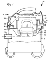
- FIGS. 1 and 2 show an embodiment of the device according to the invention in the form of a suction device 10 for a nipple.
- a suction device 10 for a nipple.
- the suction device 10 comprises a lower part 11 designed as a collecting container, a middle part 12 and an upper part 13, which are bolted together in the assembled state.
- an inlet pipe 14 for a suction channel for example.
- a known per se suction hose (not shown).
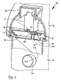
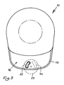
- the middle part 12 has a bottom 15. Below the bottom 15 ribs 16 are formed for mounting and / or air duct, on which a blower motor 17 known per se is provided. As well as out FIG. 3 can be seen, a prechamber 18 is formed above a portion of the bottom 15. The pre-chamber 18 is formed from the bottom 15 and a cover 19. The cover 19 has a passage 21 which connects the interior of the upper part 13 with the pre-chamber 18. Like from the Figures 2 and 3 can be seen, the bottom 15 in the region of the prechamber 18 on a false air opening 22, which connects the prechamber 18 with the interior of the lower part 11. The opening cross section of the false air opening 22 is continuously adjustable in the embodiment by means of a control element 23 in the form of a setting wheel (see in particular FIG. 3 ). The thumbwheel 23 is rotatably mounted on the underside of the cover 19.
- the upper part 13 forms with a further portion of the bottom 15 an outlet opening 24 for the suction air flow S and an inlet opening 35 for false air.
- a known switch 25 is also pivotally mounted for switching on and off of the operating current.
- the suction device 10 generates in operation in a conventional manner by means of the blower motor 17, a suction air flow S, starting from a suction nozzle (not shown) via a suction channel, for example.
- a suction pipe and / or a suction hose (not shown) until the suction air flow S enters through the inlet port 14 into the interior of the lower part 11.
- the suction air flow S is then passed as usual through a seal 36 sealed against the lower part 11 by means of a filter 26 and passed on the blower motor 17 past into the interior of the upper part 13 and from there to the outside.
- the suction air flow S exits through the outlet opening 24 from the upper part 13.
- the false air opening 22 is at least partially opened by means of the setting wheel 23, false air is sucked through the inlet opening 35 into the interior of the upper part 13.
- the false air flow F thus produced enters through the passage opening 21 in the cover 19 in the pre-chamber 18 and is then passed through the more or less open false air opening 22 into the interior of the lower part 11.
- the predetermined by the performance of the blower motor 17 suction power is reduced, whereby the suction air flow S is attenuated at the suction nozzle.
- This regulation of the suction air flow prevents the suction nozzle from becoming trapped or damaging the surface to be cleaned.
- the upper part 13 exerts an additional insulating effect, on the one hand by the acoustic shielding caused by the housing and on the other hand due to the large flow cross section within the upper part 13 made available by the false airflow F. This causes the flow velocity of the secondary air flow F and thus also of the False airflow F generated noise can be substantially reduced.
- the thumbwheel 23 is formed in the embodiment as a cylindrical hollow body, with a cylinder wall 27 and an upper wall portion 28 and a lower wall portion 29.
- the upper wall portion 28 and the lower wall portion 29 are provided with aligned bearing bores 31 for receiving a bearing shaft 32 (see. FIG. 5 ).
- the thumbwheel 23 is rotatably mounted by means of the bearing axis 32 on the cover 19 of the antechamber 18 (see. FIG. 5 ).
- the thumbwheel 23 also has in the cylinder wall 27 and in the lower wall portion 27 each have an access opening 33 and an outlet opening 34 for the entering into the prechamber 18 false air.
- the outlet opening 34 is brought more or less into coincidence by turning the setting wheel 23 with the false air opening 22.
- the false air opening 22 can be completely closed by the lower wall part 29 of the setting wheel 23 or completely brought into coincidence with the outlet opening 34, ie be completely open.
Landscapes
- Engineering & Computer Science (AREA)
- Mechanical Engineering (AREA)
- Nozzles For Electric Vacuum Cleaners (AREA)
- Exhaust Gas After Treatment (AREA)
Abstract
Description
- Die vorliegende Erfindung betrifft eine Vorrichtung zur Regulierung des Saugluftstroms eines Saugers mittels Falschluft.
- Ein Sauger umfasst üblicherweise eine Saugdüse, einen Saugkanal und ein Sauggerät. Der Saugluftstrom tritt durch die Saugdüse in den Saugkanal ein und strömt weiter in das Sauggerät. Im Sauggerät wird der Saugluftstrom durch eine Filtereinrichtung geleitet, so dass Staub und Schmutz in einem im Sauggerät vorgesehenen Sammelbehälter aufgefangen werden. Für unterschiedliche zu reinigende Flächen (Parkett, Teppiche, Möbel etc.) ist ein unterschiedlich starker Saugluftstrom erforderlich. Es soll vermieden werden, dass sich die Saugdüse an der zu reinigenden Fläche festsaugt und dass empfindliche Oberflächen Schaden nehmen.
- Zu diesem Zweck sind zahlreiche Vorrichtungen zur Regulierung des Saugluftstroms bekannt, mit denen dem Saugluftstrom Falschluft zugeführt wird. Insbesondere im gewerblichen Bereich besteht die erhöhte Anforderung, dass an die Zuverlässigkeit eines Saugers besonders hohe Anforderungen gestellt werden, so dass oft mechanische Vorrichtungen zur Regulierung des Saugluftstroms eingesetzt werden. In der Regel wird die Falschluft in eine Öffnung des Saugkanals eingeleitet, wobei die Öffnung mit einem an einem Handgriff angeordneten Schieber steuerbar ist. Dies führt jedoch zu einer zusätzlichen erheblichen Geräuschentwicklung, die vor allem im gewerblichen Bereich nicht erwünscht ist.
- Die
DE 10 2005 010 983 B3 beschreibt einen Luftstromregler im Saugkanal eines Staubsaugers, dessen Geräuschentwicklung reduziert ist, weil die Falschluft parallel zur Strömungsrichtung der Saugluft zugeführt wird. Hierfür weist der Saugkanal in einem Erweiterungsabschnitt Falschluftöffnungen auf, die mittels einer den Saugkanal umgreifenden drehbaren Hülse stufenlos geöffnet und geschlossen werden können. Diese Lösung ist jedoch konstruktiv aufwändig und daher mit vergleichsweise hohen Herstellungskosten verbunden. - Die
DE 1 879 398 U schlägt dagegen vor, den Luftstromregler in der Saugdüse selbst anzuordnen. Der Luftstromregler ist dabei als stufenlos verstellbarer Schieber ausgebildet, der einer in der Unterseite der Saugdüse vorgesehenen Öffnung zugeordnet ist, durch welche die Falschluft in die Saugdüse eintritt. Diese Lösung hat jedoch den Nachteil, dass der Luftstromregler beim Wechsel der Saugdüse (bspw. von einer Teppichdüse zu einer Möbeldüse) verloren geht und auch nicht in allen Saugdüsen konstruktiv verwirklicht werden kann. - Die Aufgabe der vorliegenden Erfindung besteht somit darin, eine Vorrichtung zur Regulierung des Saugluftstroms eines Saugers bereitzustellen, die konstruktiv einfach aufgebaut ist und die Regulierung des Saugluftstroms mit möglichst geringer zusätzlicher Geräuschentwicklung ermöglicht.
- Die Lösung besteht in einer Vorrichtung mit den Merkmalen des Patentanspruchs 1. Erfindungsgemäß ist vorgesehen, dass ein Sauggerät für den Sauger vorgesehen ist, das mindestens eine Falschluftöffnung aufweist, deren Öffnungsquerschnitt mittels eines Steuerelements derart steuerbar ist, dass Falschluft dem Saugluftstrom zuführbar ist.
- Gemäß der vorliegenden Erfindung wird der Saugluftstrom weder in der Saugdüse noch im Saugkanal, sondern mittels einer im Sauggerät angeordneten Falschluftöffnung reguliert. Die mit dem Ansaugen der Falschluft verbundene Geräuschentwicklung wird durch das Gehäuse des Sauggeräts wirksam gedämpft. Zusätzlich befindet sich das Sauggerät, im Gegensatz zum Saugkanal, in einiger Entfernung von der den Sauger bedienenden Reinigungskraft, wodurch die Lärmbelastung noch weiter vermindert wird. Die erfindungsgemäße Vorrichtung arbeitet rein mechanisch, ist konstruktiv einfach aufgebaut und kann damit kostengünstig verwirklicht werden. Bereits vorhandene Sauggeräte können nachgerüstet werden.
- Vorteilhafte Weiterbildungen ergeben sich aus den Unteransprüchen.
- Das Steuerelement kann beliebig ausgestaltet sein, wobei eine Ausgestaltung als Schieber oder Stellrad besonders zweckmäßig ist. Es ist ferner von Vorteil, wenn der Öffnungsquerschnitt der Falschluftöffnung mittels des Steuerelements stufenlos steuerbar ist, um eine optimale Anpassung an die zu reinigende Fläche zu ermöglichen.
- Die erfindungsgemäße Vorrichtung kann mit Sauggeräten aller Art verwirklicht werden. Übliche Sauggeräte weisen ein als Sammelbehälter ausgebildetes Unterteil und ein Oberteil auf, auch wenn theoretisch eine erfindungsgemäße Vorrichtung mit einem einteilig ausgebildeten Sauggerät denkbar ist. Der Gebläsemotor kann dabei in einem beliebigen Teil des Gehäuses (bspw. im Oberteil oder im Unterteil) angeordnet sein. Zweckmäßigerweise kann die Falschluftöffnung im Oberteil vorgesehen sein, derart dass eine Strömungsverbindung zwischen 0berteil und Unterteil ausgebildet ist. Da der Einlassstutzen für den Saugkanal am als Sammelbehälter ausgebildeten Unterteil angeordnet ist, ist auf diese Weise sichergestellt, dass die Falschluft dem Saugluftstrom zuführbar ist.
- Eine bevorzugte Weiterbildung besteht darin, dass die Falschluftöffnung in einer im Oberteil ausgebildeten Vorkammer angeordnet ist. Die Vorkammer bewirkt eine zusätzliche Dämpfung der Geräuschentwicklung.
- Eine weitere vorteilhafte Weiterbildung sieht vor, dass das Sauggerät ein als Sammelbehälter ausgebildetes Unterteil und ein Oberteil sowie ein zwischen Unterteil und Oberteil angeordnetes Mittelteil aufweist und dass die Falschluftöffnung im Mittelteil vorgesehen ist, derart dass eine Strömungsverbindung zwischen Mittelteil und Unterteil ausgebildet ist. Die Falschluft ist bei dieser Ausgestaltung über das Mittelteil und das Unterteil dem Saugluftstrom zuführbar. Bei dieser Ausgestaltung kann zur zusätzlichen Geräuschdämpfung im Mittelteil ebenfalls eine Vorkammer vorgesehen sein, in der die Falschluftöffnung angeordnet ist.
- Eine bevorzugte Ausführungsform ist dadurch gekennzeichnet, dass die Falschluftöffnung im Mittelteil vorgesehen ist und dass im Oberteil eine Eintrittsöffnung für die Falschluft vorgesehen ist, derart dass eine Strömungsverbindung zwischen Oberteil und Unterteil ausgebildet ist.
- Die räumliche Trennung der Falschluftöffnung von einer separaten Eintrittsöffnung für die Falschluft im Oberteil hat den Vorteil, dass eine Nachrüstung bereits in der Produktion befindlicher Sauggeräte besonders einfach möglich ist. Bei dieser Ausgestaltung kann zur zusätzlichen Geräuschdämpfung im Mittelteil ebenfalls eine Vorkammer vorgesehen sein, in der die Falschluftöffnung angeordnet ist.
- Ein Ausführungsbeispiel der vorliegenden Erfindung wird im Folgenden anhand der beigefügten Zeichnungen näher beschrieben. Es zeigen in schematischer, nicht maßstabsgetreuer Darstellung:
- Figur 1
- ein erstes Ausführungsbeispiel einer erfindungsgemäßen Vorrichtung, teilweise im Schnitt;
- Figur 2
- die Vorrichtung gemäß
Figur 1 in einer Teilansicht in Richtung des Pfeils A inFigur 1 , teilweise im Schnitt; - Figur 3
- die Vorrichtung gemäß
Figur 1 in einer Draufsicht bei entferntem Oberteil; - Figur4a
- das Steuerelement der Vorrichtung gemäß
Figur 1 im Schnitt; - Figur 4b
- das Steuerelement gemäß
Figur 4a in einer Seitenansicht; - Figur 4c
- einen Schnitt entlang der Linie IVc - IVc in
Figur 4a ; - Figur 5
- das Steuerelement 4a innerhalb der Vorrichtung gemäß
Figur 1 . - Die
Figuren 1 und2 zeigen ein Ausführungsbeispiel der erfindungsgemäßen Vorrichtung in Form eines Sauggerätes 10 für einen Sauger. Dabei kann es sich sowohl um einen Trockensauger als auch um einen Nass-/Trockensauger handeln. Das Sauggerät 10 umfasst im Ausführungsbeispiel ein als Sammelbehälter ausgebildetes Unterteil 11, ein Mittelteil 12 und ein 0berteil 13, die im zusammengebauten Zustand miteinander verschraubt sind. Am Unterteil 11 ist ein Einlassstutzen 14 für einen Saugkanal, bspw. in Form eines in an sich bekannten Saugschlauchs (nicht dargestellt) vorgesehen. - Das Mittelteil 12 weist einen Boden 15 auf. Unterhalb des Bodens 15 sind Rippen 16 zur Halterung und/oder Luftführung angeformt, an denen ein an sich bekannter Gebläsemotor 17 vorgesehen ist. Wie auch aus
Figur 3 zu entnehmen ist, ist oberhalb eines Teilbereichs des Bodens 15 eine Vorkammer 18 angeformt. Die Vorkammer 18 ist aus dem Boden 15 und einer Abdeckung 19 gebildet. Die Abdeckung 19 weist einen Durchlass 21 auf, welcher das Innere des Oberteils 13 mit der Vorkammer 18 verbindet. Wie aus denFiguren 2 und3 zu erkennen ist, weist der Boden 15 im Bereich der Vorkammer 18 eine Falschluftöffnung 22 auf, welche die Vorkammer 18 mit dem Inneren des Unterteils 11 verbindet. Der Öffnungsquerschnitt der Falschluftöffnung 22 ist im Ausführungsbeispiel mittels eines Steuerelements 23 in Form eines Stellrades stufenlos einstellbar (siehe insbesondereFigur 3 ). Das Stellrad 23 ist an der Unterseite der Abdeckung 19 drehbar gelagert. - Das Oberteil 13 bildet mit einem weiteren Teilbereich des Bodens 15 eine Auslassöffnung 24 für den Saugluftstrom S sowie eine Eintrittsöffnung 35 für Falschluft. Im Oberteil 13 ist ferner ein an sich bekannter Schalter 25 zum Ein- und Ausschalten des Betriebsstroms schwenkbar gelagert.
- Wie es in den
Figuren 1 und2 anhand der Pfeile dargestellt ist, erzeugt das Sauggerät 10 im Betrieb in an sich bekannter Weise mittels des Gebläsemotors 17 einen Saugluftstrom S, ausgehend von einer Saugdüse (nicht dargestellt) über einen Saugkanal, bspw. ein Saugrohr und/oder einen Saugschlauch (nicht dargestellt), bis der Saugluftstrom S durch den Einlassstutzen 14 in das Innere des Unterteils 11 eintritt. Der Saugluftstrom S wird anschließend wie üblich durch einen mittels einer Dichtung 36 gegen das Unterteil 11 abgedichteten Filter 26 geleitet und am Gebläsemotor 17 vorbei in das Innere des Oberteils 13 und von dort nach außen geleitet. Im Ausführungsbeispiel tritt der Saugluftstrom S durch die Auslassöffnung 24 aus dem Oberteil 13 aus. - Falls die Falschluftöffnung 22 mittels des Stellrads 23 zumindest teilweise geöffnet ist, wird Falschluft durch die Eintrittsöffnung 35 in das Innere des Oberteils 13 gesaugt. Der so erzeugte Falschluftstrom F tritt durch die Durchlassöffnung 21 in der Abdeckung 19 in die Vorkammer 18 ein und wird anschließend durch die mehr oder weniger geöffnete Falschluftöffnung 22 in das Innere des Unterteils 11 geleitet. Dadurch wird die von der Leistung des Gebläsemotors 17 vorgegebene Saug leistung vermindert, wodurch der Saugluftstrom S an der Saugdüse abgeschwächt wird. Durch diese Regulierung des Saugluftstroms wird verhindert, dass sich die Saugdüse an der zu reinigenden Oberfläche festsaugt bzw. diese beschädigt. Der Umstand, dass die Falschluft in das Sauggerät 10 geleitet und in diesem Ausführungsbeispiel zusätzlich durch die Vorkammer 18 geführt wird, sorgt für eine ganz erhebliche Verringerung der mit dem Ansaugen und Einleiten der Falschluft verbundenen zusätzlichen Geräusche. Das Oberteil 13 übt eine zusätzliche Dämmwirkung aus, und zwar einerseits durch die vom Gehäuse bewirkte akustische Abschirmung und andererseits aufgrund des dem Falschluftstrom F zur Verfügung gestellten großen Strömungsquerschnitts innerhalb des Oberteils 13. Dies bewirkt, dass die Strömungsgeschwindigkeit des Falschluftstroms F und damit auch der vom Falschluftstrom F erzeugte Lärm wesentlich reduziert werden.
- Das im Ausführungsbeispiel als Steuerelement dienende Stellrad 23 ist in den
Figuren 4a bis 5 im Detail dargestellt. Das Stellrad 23 ist im Ausführungsbeispiel als zylindrischer Hohlkörper ausgebildet, mit einer Zylinderwand 27 sowie einem oberen Wandteil 28 und einem unteren Wandteil 29. Das obere Wandteil 28 und das untere Wandteil 29 sind mit fluchtenden Lagerbohrungen 31 zur Aufnahme einer Lagerachse 32 versehen (vgl.Figur 5 ). Das Stellrad 23 ist mittels der Lagerachse 32 an der Abdeckung 19 der Vorkammer 18 drehbar gelagert (vgl.Figur 5 ). Das Stellrad 23 weist ferner in der Zylinderwand 27 sowie im unteren Wandteil 27 je eine Zugangsöffnung 33 und eine Ausgangsöffnung 34 für die in die Vorkammer 18 eintretende Falschluft auf. Zur Regulierung des Saugluftstroms S wird die Ausgangsöffnung 34 durch Drehen des Stellrads 23 mit der Falschluftöffnung 22 mehr oder weniger in Deckung gebracht. Im äußersten Fall kann die Falschluftöffnung 22 vom unteren Wandteil 29 des Stellrads 23 vollständig verschlossen sein bzw. vollständig mit der Ausgangsöffnung 34 in Deckung gebracht, d.h. vollständig geöffnet sein.
Claims (10)
- Vorrichtung zur Regulierung des Saugluftstroms (S) eines Saugers mittels Falschluft, dadurch gekennzeichnet, dass ein Sauggerät (10) für den Sauger vorgesehen ist, das mindestens eine Falschluftöffnung (22) aufweist, deren Öffnungsquerschnitt mittels eines Steuerelements (23) derart steuerbar ist, dass Falschluft dem Saugluftstrom (S) zuführbar ist.
- Vorrichtung nach Anspruch 1, dadurch gekennzeichnet, dass das Steuerelement (23) als Schieber ausgebildet ist.
- Vorrichtung nach Anspruch 1, dadurch gekennzeichnet, dass das Steuerelement (23) als Stellrad ausgebildet ist.
- Vorrichtung nach einem der vorhergehenden Ansprüche, dadurch gekennzeichnet, dass der Öffnungsquerschnitt der Falschluftöffnung (22) mittels des Steuerelements (23) stufenlos steuerbar ist.
- Vorrichtung nach einem der vorhergehenden Ansprüche, dadurch gekennzeichnet, dass das Sauggerät (10) ein als Sammelbehälter ausgebildetes Unterteil (11) und ein Oberteil (13) aufweist und dass die Falschluftöffnung im Oberteil (13) vorgesehen ist, derart dass eine Strömungsverbindung zwischen Oberteil (13) und Unterteil (11) ausgebildet ist.
- Vorrichtung nach Anspruch 5, dadurch gekennzeichnet, dass die Falschluftöffnung in einer im Oberteil (13) ausgebildeten Vorkammer angeordnet ist.
- Vorrichtung nach einem der Ansprüche 1 bis 4, dadurch gekennzeichnet, dass das Sauggerät (10) ein als Sammelbehälter ausgebildetes Unterteil (11) und ein Oberteil (13) sowie ein zwischen Unterteil (11) und Oberteil (13) angeordnetes Mittelteil (12) aufweist und dass die Falschluftöffnung im Mittelteil (12) vorgesehen ist, derart dass eine Strömungsverbindung zwischen Mittelteil (12) und Unterteil (13) ausgebildet ist.
- Vorrichtung nach Anspruch 7, dadurch gekennzeichnet, dass die Falschluftöffnung in einer im Mittelteil (12) ausgebildeten Vorkammer angeordnet ist.
- Vorrichtung nach einem der Ansprüche 1 bis 4, dadurch gekennzeichnet, dass das Sauggerät (10) ein als Sammelbehälter ausgebildetes Unterteil (11) und ein Oberteil (13) sowie ein zwischen Unterteil (11) und Oberteil (13) angeordnetes Mittelteil (12) aufweist, dass die Falschluftöffnung (22) im Mittelteil (12) vorgesehen ist und dass im Oberteil (13) eine Eintrittsöffnung (35) für die Falschluft vorgesehen ist, derart dass eine Strömungsverbindung zwischen Oberteil (11) und Unterteil (13) ausgebildet ist.
- Vorrichtung nach Anspruch 9, dadurch gekennzeichnet, dass die Falschluftöffnung (22) in einer im Mittelteil (12) ausgebildeten Vorkammer (18) angeordnet ist.
Applications Claiming Priority (1)
| Application Number | Priority Date | Filing Date | Title |
|---|---|---|---|
| DE200810024605 DE102008024605A1 (de) | 2008-05-21 | 2008-05-21 | Vorrichtung zur Regulierung des Saugluftstroms eines Saugers |
Publications (3)
| Publication Number | Publication Date |
|---|---|
| EP2123204A2 true EP2123204A2 (de) | 2009-11-25 |
| EP2123204A3 EP2123204A3 (de) | 2012-07-04 |
| EP2123204B1 EP2123204B1 (de) | 2016-11-16 |
Family
ID=41050876
Family Applications (1)
| Application Number | Title | Priority Date | Filing Date |
|---|---|---|---|
| EP09004933.9A Active EP2123204B1 (de) | 2008-05-21 | 2009-04-03 | Vorrichtung zur regulierung des saugluftstroms eines saugers |
Country Status (2)
| Country | Link |
|---|---|
| EP (1) | EP2123204B1 (de) |
| DE (1) | DE102008024605A1 (de) |
Cited By (1)
| Publication number | Priority date | Publication date | Assignee | Title |
|---|---|---|---|---|
| CN113729547A (zh) * | 2020-05-29 | 2021-12-03 | 优联沃森(苏州)智能技术有限公司 | 一种恒压式家用清洁吸尘器 |
Citations (2)
| Publication number | Priority date | Publication date | Assignee | Title |
|---|---|---|---|---|
| DE1879398U (de) | 1963-04-27 | 1963-09-19 | Kicherer Fakir Werk | Saugdruckregler fuer stielstaubsauger. |
| DE102005010983B3 (de) | 2005-03-03 | 2006-08-31 | Alfred Kärcher Gmbh & Co. Kg | Luftstromregler für Staubsauger |
Family Cites Families (4)
| Publication number | Priority date | Publication date | Assignee | Title |
|---|---|---|---|---|
| DE102005017568B4 (de) * | 2005-04-11 | 2024-04-25 | Alfred Kärcher SE & Co. KG | Saugreinigungsgerät |
| KR100730232B1 (ko) * | 2006-03-06 | 2007-06-19 | 삼성광주전자 주식회사 | 진공청소기의 흡입브러쉬 |
| DE102006030227B3 (de) * | 2006-06-30 | 2008-03-27 | BSH Bosch und Siemens Hausgeräte GmbH | Nebenluftventil |
| DE202006017191U1 (de) * | 2006-11-10 | 2007-01-04 | Vorwerk & Co. Interholding Gmbh | Staubsauger mit einem Elektromotor |
-
2008
- 2008-05-21 DE DE200810024605 patent/DE102008024605A1/de not_active Withdrawn
-
2009
- 2009-04-03 EP EP09004933.9A patent/EP2123204B1/de active Active
Patent Citations (2)
| Publication number | Priority date | Publication date | Assignee | Title |
|---|---|---|---|---|
| DE1879398U (de) | 1963-04-27 | 1963-09-19 | Kicherer Fakir Werk | Saugdruckregler fuer stielstaubsauger. |
| DE102005010983B3 (de) | 2005-03-03 | 2006-08-31 | Alfred Kärcher Gmbh & Co. Kg | Luftstromregler für Staubsauger |
Cited By (1)
| Publication number | Priority date | Publication date | Assignee | Title |
|---|---|---|---|---|
| CN113729547A (zh) * | 2020-05-29 | 2021-12-03 | 优联沃森(苏州)智能技术有限公司 | 一种恒压式家用清洁吸尘器 |
Also Published As
| Publication number | Publication date |
|---|---|
| DE102008024605A1 (de) | 2009-11-26 |
| EP2123204A3 (de) | 2012-07-04 |
| EP2123204B1 (de) | 2016-11-16 |
Similar Documents
| Publication | Publication Date | Title |
|---|---|---|
| DE4425863C2 (de) | Saug- und Blasvorrichtung | |
| DE1404894A1 (de) | Vorrichtung zum Auffangen und Ausscheiden von Faserflug und Staub im Abluftkanal vonBelueftungs- oder Klimaanlagen in Textilbetrieben,insbesondere Spinnereien und Webereien | |
| EP2937015A1 (de) | Arbeitstisch | |
| DE1628467A1 (de) | Liegender Staubsauger | |
| EP2123204A2 (de) | Vorrichtung zur Regulierung des Saugluftstroms eines Saugers | |
| DE102015101339A1 (de) | Saugdüse zum Saugen von Hartbodenflächen | |
| EP3669732B1 (de) | Staubsaugerdüse, insbesondere statische staubsaugerbodendüse | |
| DE9208718U1 (de) | Bauelement einer Lüftungsinstallation | |
| EP3195780A1 (de) | Saugdüse | |
| DE1510727C3 (de) | Pneumatische Reimgungsvorrich tung an Textilmaschinen | |
| EP3500145A1 (de) | Bodendüse für einen staubsauger, verfahren zum absaugen von textilflächen und staubsauger | |
| DE19528286A1 (de) | Abscheider für mit Feststoff- oder Flüssigpartikeln beladene Gasströme | |
| DE19851405C2 (de) | Zusatzvorrichtung für statische Staubsaugerdüsen | |
| DE202019101089U1 (de) | Vorrichtung zum Absaugen von Luft | |
| EP0394886B1 (de) | Saugaggregat | |
| DE102012107051B4 (de) | Reinigungsgerät | |
| EP1714734A1 (de) | Staubabsaugeinrichtung zur lösbaren Anbringung an einem Werkzeuggerät, mit schiebenden Ansaugbereich | |
| DE3426012C2 (de) | ||
| DE102018211880A1 (de) | Strassenfräsmaschine | |
| EP3763271B1 (de) | Bodendüse für eine saugeinrichtung zur reinigung und pflege von bodenflächen | |
| DE3149469C2 (de) | Elektroabscheider | |
| DE3003563A1 (de) | Mit sammelraum kombinierter zyklon | |
| EP4449962A1 (de) | Sauggerät mit mindestens drei turbinen | |
| EP4649871A1 (de) | Saugreinigungsgerät | |
| DE102006023747A1 (de) | Pumpe zur Reinigung eines Bohrloches |
Legal Events
| Date | Code | Title | Description |
|---|---|---|---|
| PUAI | Public reference made under article 153(3) epc to a published international application that has entered the european phase |
Free format text: ORIGINAL CODE: 0009012 |
|
| AK | Designated contracting states |
Kind code of ref document: A2 Designated state(s): AT BE BG CH CY CZ DE DK EE ES FI FR GB GR HR HU IE IS IT LI LT LU LV MC MK MT NL NO PL PT RO SE SI SK TR |
|
| PUAL | Search report despatched |
Free format text: ORIGINAL CODE: 0009013 |
|
| AK | Designated contracting states |
Kind code of ref document: A3 Designated state(s): AT BE BG CH CY CZ DE DK EE ES FI FR GB GR HR HU IE IS IT LI LT LU LV MC MK MT NL NO PL PT RO SE SI SK TR |
|
| AX | Request for extension of the european patent |
Extension state: AL BA RS |
|
| RIC1 | Information provided on ipc code assigned before grant |
Ipc: A47L 9/00 20060101AFI20120525BHEP |
|
| 17P | Request for examination filed |
Effective date: 20130423 |
|
| RAP1 | Party data changed (applicant data changed or rights of an application transferred) |
Owner name: SPRINTUS GMBH |
|
| 17Q | First examination report despatched |
Effective date: 20150513 |
|
| GRAP | Despatch of communication of intention to grant a patent |
Free format text: ORIGINAL CODE: EPIDOSNIGR1 |
|
| INTG | Intention to grant announced |
Effective date: 20160310 |
|
| GRAS | Grant fee paid |
Free format text: ORIGINAL CODE: EPIDOSNIGR3 |
|
| GRAJ | Information related to disapproval of communication of intention to grant by the applicant or resumption of examination proceedings by the epo deleted |
Free format text: ORIGINAL CODE: EPIDOSDIGR1 |
|
| GRAL | Information related to payment of fee for publishing/printing deleted |
Free format text: ORIGINAL CODE: EPIDOSDIGR3 |
|
| GRAP | Despatch of communication of intention to grant a patent |
Free format text: ORIGINAL CODE: EPIDOSNIGR1 |
|
| INTC | Intention to grant announced (deleted) | ||
| GRAA | (expected) grant |
Free format text: ORIGINAL CODE: 0009210 |
|
| INTG | Intention to grant announced |
Effective date: 20160923 |
|
| AK | Designated contracting states |
Kind code of ref document: B1 Designated state(s): AT BE BG CH CY CZ DE DK EE ES FI FR GB GR HR HU IE IS IT LI LT LU LV MC MK MT NL NO PL PT RO SE SI SK TR |
|
| REG | Reference to a national code |
Ref country code: GB Ref legal event code: FG4D Free format text: NOT ENGLISH |
|
| REG | Reference to a national code |
Ref country code: CH Ref legal event code: EP |
|
| REG | Reference to a national code |
Ref country code: IE Ref legal event code: FG4D Free format text: LANGUAGE OF EP DOCUMENT: GERMAN |
|
| REG | Reference to a national code |
Ref country code: AT Ref legal event code: REF Ref document number: 845073 Country of ref document: AT Kind code of ref document: T Effective date: 20161215 |
|
| REG | Reference to a national code |
Ref country code: DE Ref legal event code: R096 Ref document number: 502009013370 Country of ref document: DE |
|
| REG | Reference to a national code |
Ref country code: NL Ref legal event code: FP |
|
| PG25 | Lapsed in a contracting state [announced via postgrant information from national office to epo] |
Ref country code: LV Free format text: LAPSE BECAUSE OF FAILURE TO SUBMIT A TRANSLATION OF THE DESCRIPTION OR TO PAY THE FEE WITHIN THE PRESCRIBED TIME-LIMIT Effective date: 20161116 |
|
| REG | Reference to a national code |
Ref country code: LT Ref legal event code: MG4D |
|
| REG | Reference to a national code |
Ref country code: FR Ref legal event code: PLFP Year of fee payment: 9 |
|
| PG25 | Lapsed in a contracting state [announced via postgrant information from national office to epo] |
Ref country code: NO Free format text: LAPSE BECAUSE OF FAILURE TO SUBMIT A TRANSLATION OF THE DESCRIPTION OR TO PAY THE FEE WITHIN THE PRESCRIBED TIME-LIMIT Effective date: 20170216 Ref country code: GR Free format text: LAPSE BECAUSE OF FAILURE TO SUBMIT A TRANSLATION OF THE DESCRIPTION OR TO PAY THE FEE WITHIN THE PRESCRIBED TIME-LIMIT Effective date: 20170217 Ref country code: SE Free format text: LAPSE BECAUSE OF FAILURE TO SUBMIT A TRANSLATION OF THE DESCRIPTION OR TO PAY THE FEE WITHIN THE PRESCRIBED TIME-LIMIT Effective date: 20161116 Ref country code: LT Free format text: LAPSE BECAUSE OF FAILURE TO SUBMIT A TRANSLATION OF THE DESCRIPTION OR TO PAY THE FEE WITHIN THE PRESCRIBED TIME-LIMIT Effective date: 20161116 |
|
| PG25 | Lapsed in a contracting state [announced via postgrant information from national office to epo] |
Ref country code: PL Free format text: LAPSE BECAUSE OF FAILURE TO SUBMIT A TRANSLATION OF THE DESCRIPTION OR TO PAY THE FEE WITHIN THE PRESCRIBED TIME-LIMIT Effective date: 20161116 Ref country code: FI Free format text: LAPSE BECAUSE OF FAILURE TO SUBMIT A TRANSLATION OF THE DESCRIPTION OR TO PAY THE FEE WITHIN THE PRESCRIBED TIME-LIMIT Effective date: 20161116 Ref country code: PT Free format text: LAPSE BECAUSE OF FAILURE TO SUBMIT A TRANSLATION OF THE DESCRIPTION OR TO PAY THE FEE WITHIN THE PRESCRIBED TIME-LIMIT Effective date: 20170316 Ref country code: HR Free format text: LAPSE BECAUSE OF FAILURE TO SUBMIT A TRANSLATION OF THE DESCRIPTION OR TO PAY THE FEE WITHIN THE PRESCRIBED TIME-LIMIT Effective date: 20161116 Ref country code: ES Free format text: LAPSE BECAUSE OF FAILURE TO SUBMIT A TRANSLATION OF THE DESCRIPTION OR TO PAY THE FEE WITHIN THE PRESCRIBED TIME-LIMIT Effective date: 20161116 |
|
| PG25 | Lapsed in a contracting state [announced via postgrant information from national office to epo] |
Ref country code: SK Free format text: LAPSE BECAUSE OF FAILURE TO SUBMIT A TRANSLATION OF THE DESCRIPTION OR TO PAY THE FEE WITHIN THE PRESCRIBED TIME-LIMIT Effective date: 20161116 Ref country code: CZ Free format text: LAPSE BECAUSE OF FAILURE TO SUBMIT A TRANSLATION OF THE DESCRIPTION OR TO PAY THE FEE WITHIN THE PRESCRIBED TIME-LIMIT Effective date: 20161116 Ref country code: EE Free format text: LAPSE BECAUSE OF FAILURE TO SUBMIT A TRANSLATION OF THE DESCRIPTION OR TO PAY THE FEE WITHIN THE PRESCRIBED TIME-LIMIT Effective date: 20161116 Ref country code: RO Free format text: LAPSE BECAUSE OF FAILURE TO SUBMIT A TRANSLATION OF THE DESCRIPTION OR TO PAY THE FEE WITHIN THE PRESCRIBED TIME-LIMIT Effective date: 20161116 Ref country code: DK Free format text: LAPSE BECAUSE OF FAILURE TO SUBMIT A TRANSLATION OF THE DESCRIPTION OR TO PAY THE FEE WITHIN THE PRESCRIBED TIME-LIMIT Effective date: 20161116 |
|
| REG | Reference to a national code |
Ref country code: DE Ref legal event code: R097 Ref document number: 502009013370 Country of ref document: DE |
|
| PG25 | Lapsed in a contracting state [announced via postgrant information from national office to epo] |
Ref country code: BG Free format text: LAPSE BECAUSE OF FAILURE TO SUBMIT A TRANSLATION OF THE DESCRIPTION OR TO PAY THE FEE WITHIN THE PRESCRIBED TIME-LIMIT Effective date: 20170216 |
|
| PGFP | Annual fee paid to national office [announced via postgrant information from national office to epo] |
Ref country code: AT Payment date: 20170420 Year of fee payment: 9 |
|
| PLBE | No opposition filed within time limit |
Free format text: ORIGINAL CODE: 0009261 |
|
| STAA | Information on the status of an ep patent application or granted ep patent |
Free format text: STATUS: NO OPPOSITION FILED WITHIN TIME LIMIT |
|
| 26N | No opposition filed |
Effective date: 20170817 |
|
| PG25 | Lapsed in a contracting state [announced via postgrant information from national office to epo] |
Ref country code: SI Free format text: LAPSE BECAUSE OF FAILURE TO SUBMIT A TRANSLATION OF THE DESCRIPTION OR TO PAY THE FEE WITHIN THE PRESCRIBED TIME-LIMIT Effective date: 20161116 |
|
| REG | Reference to a national code |
Ref country code: CH Ref legal event code: PL |
|
| REG | Reference to a national code |
Ref country code: DE Ref legal event code: R082 Ref document number: 502009013370 Country of ref document: DE Representative=s name: GLAWE DELFS MOLL PARTNERSCHAFT MBB VON PATENT-, DE Ref country code: DE Ref legal event code: R081 Ref document number: 502009013370 Country of ref document: DE Owner name: SPRINTUS GMBH, DE Free format text: FORMER OWNER: SPRINTUS GMBH, 71554 WEISSACH, DE |
|
| REG | Reference to a national code |
Ref country code: IE Ref legal event code: MM4A |
|
| PG25 | Lapsed in a contracting state [announced via postgrant information from national office to epo] |
Ref country code: MC Free format text: LAPSE BECAUSE OF FAILURE TO SUBMIT A TRANSLATION OF THE DESCRIPTION OR TO PAY THE FEE WITHIN THE PRESCRIBED TIME-LIMIT Effective date: 20161116 |
|
| PG25 | Lapsed in a contracting state [announced via postgrant information from national office to epo] |
Ref country code: CH Free format text: LAPSE BECAUSE OF NON-PAYMENT OF DUE FEES Effective date: 20170430 Ref country code: LI Free format text: LAPSE BECAUSE OF NON-PAYMENT OF DUE FEES Effective date: 20170430 Ref country code: LU Free format text: LAPSE BECAUSE OF NON-PAYMENT OF DUE FEES Effective date: 20170403 |
|
| REG | Reference to a national code |
Ref country code: BE Ref legal event code: MM Effective date: 20170430 |
|
| REG | Reference to a national code |
Ref country code: FR Ref legal event code: PLFP Year of fee payment: 10 |
|
| PG25 | Lapsed in a contracting state [announced via postgrant information from national office to epo] |
Ref country code: IE Free format text: LAPSE BECAUSE OF NON-PAYMENT OF DUE FEES Effective date: 20170403 |
|
| REG | Reference to a national code |
Ref country code: FR Ref legal event code: CA Effective date: 20180330 |
|
| PG25 | Lapsed in a contracting state [announced via postgrant information from national office to epo] |
Ref country code: BE Free format text: LAPSE BECAUSE OF NON-PAYMENT OF DUE FEES Effective date: 20170430 |
|
| PG25 | Lapsed in a contracting state [announced via postgrant information from national office to epo] |
Ref country code: MT Free format text: LAPSE BECAUSE OF FAILURE TO SUBMIT A TRANSLATION OF THE DESCRIPTION OR TO PAY THE FEE WITHIN THE PRESCRIBED TIME-LIMIT Effective date: 20161116 |
|
| REG | Reference to a national code |
Ref country code: AT Ref legal event code: MM01 Ref document number: 845073 Country of ref document: AT Kind code of ref document: T Effective date: 20180403 |
|
| PG25 | Lapsed in a contracting state [announced via postgrant information from national office to epo] |
Ref country code: AT Free format text: LAPSE BECAUSE OF NON-PAYMENT OF DUE FEES Effective date: 20180403 |
|
| PG25 | Lapsed in a contracting state [announced via postgrant information from national office to epo] |
Ref country code: HU Free format text: LAPSE BECAUSE OF FAILURE TO SUBMIT A TRANSLATION OF THE DESCRIPTION OR TO PAY THE FEE WITHIN THE PRESCRIBED TIME-LIMIT; INVALID AB INITIO Effective date: 20090403 |
|
| PG25 | Lapsed in a contracting state [announced via postgrant information from national office to epo] |
Ref country code: CY Free format text: LAPSE BECAUSE OF NON-PAYMENT OF DUE FEES Effective date: 20161116 |
|
| PG25 | Lapsed in a contracting state [announced via postgrant information from national office to epo] |
Ref country code: MK Free format text: LAPSE BECAUSE OF FAILURE TO SUBMIT A TRANSLATION OF THE DESCRIPTION OR TO PAY THE FEE WITHIN THE PRESCRIBED TIME-LIMIT Effective date: 20161116 |
|
| PG25 | Lapsed in a contracting state [announced via postgrant information from national office to epo] |
Ref country code: TR Free format text: LAPSE BECAUSE OF FAILURE TO SUBMIT A TRANSLATION OF THE DESCRIPTION OR TO PAY THE FEE WITHIN THE PRESCRIBED TIME-LIMIT Effective date: 20161116 |
|
| PG25 | Lapsed in a contracting state [announced via postgrant information from national office to epo] |
Ref country code: IS Free format text: LAPSE BECAUSE OF FAILURE TO SUBMIT A TRANSLATION OF THE DESCRIPTION OR TO PAY THE FEE WITHIN THE PRESCRIBED TIME-LIMIT Effective date: 20170316 |
|
| REG | Reference to a national code |
Ref country code: DE Ref legal event code: R082 Ref document number: 502009013370 Country of ref document: DE Representative=s name: GLAWE DELFS MOLL PARTNERSCHAFT MBB VON PATENT-, DE Ref country code: DE Ref legal event code: R082 Ref document number: 502009013370 Country of ref document: DE Representative=s name: WITTE, WELLER & PARTNER PATENTANWAELTE MBB, DE |
|
| REG | Reference to a national code |
Ref country code: DE Ref legal event code: R082 Ref document number: 502009013370 Country of ref document: DE Representative=s name: WITTE, WELLER & PARTNER PATENTANWAELTE MBB, DE |
|
| PGFP | Annual fee paid to national office [announced via postgrant information from national office to epo] |
Ref country code: NL Payment date: 20250422 Year of fee payment: 17 |
|
| PGFP | Annual fee paid to national office [announced via postgrant information from national office to epo] |
Ref country code: DE Payment date: 20250417 Year of fee payment: 17 |
|
| PGFP | Annual fee paid to national office [announced via postgrant information from national office to epo] |
Ref country code: GB Payment date: 20250423 Year of fee payment: 17 |
|
| PGFP | Annual fee paid to national office [announced via postgrant information from national office to epo] |
Ref country code: IT Payment date: 20250430 Year of fee payment: 17 |
|
| PGFP | Annual fee paid to national office [announced via postgrant information from national office to epo] |
Ref country code: FR Payment date: 20250428 Year of fee payment: 17 |