EP2120015A2 - Appareil et programme pour trouver la position d'un véhicule - Google Patents
Appareil et programme pour trouver la position d'un véhicule Download PDFInfo
- Publication number
- EP2120015A2 EP2120015A2 EP09006491A EP09006491A EP2120015A2 EP 2120015 A2 EP2120015 A2 EP 2120015A2 EP 09006491 A EP09006491 A EP 09006491A EP 09006491 A EP09006491 A EP 09006491A EP 2120015 A2 EP2120015 A2 EP 2120015A2
- Authority
- EP
- European Patent Office
- Prior art keywords
- unit
- road
- travel
- finding
- locus
- Prior art date
- Legal status (The legal status is an assumption and is not a legal conclusion. Google has not performed a legal analysis and makes no representation as to the accuracy of the status listed.)
- Granted
Links
Images


Classifications
-
- G—PHYSICS
- G01—MEASURING; TESTING
- G01C—MEASURING DISTANCES, LEVELS OR BEARINGS; SURVEYING; NAVIGATION; GYROSCOPIC INSTRUMENTS; PHOTOGRAMMETRY OR VIDEOGRAMMETRY
- G01C21/00—Navigation; Navigational instruments not provided for in groups G01C1/00 - G01C19/00
- G01C21/26—Navigation; Navigational instruments not provided for in groups G01C1/00 - G01C19/00 specially adapted for navigation in a road network
- G01C21/28—Navigation; Navigational instruments not provided for in groups G01C1/00 - G01C19/00 specially adapted for navigation in a road network with correlation of data from several navigational instruments
- G01C21/30—Map- or contour-matching
Definitions
- the present disclosure generally relates to a navigation apparatus for use in a vehicle.
- the map matching method used in the navigation apparatus typically finds the vehicle position based on the travel locus of the vehicle calculated by performing the autonomous navigation and by associating the travel locus to the map data.
- the technique disclosed in a Japanese patent document JP-A-H02-130415 approximates the travel locus of the vehicle by using a fixed length element, and matches the approximation with the map data by selecting, from among the road candidates, one that minimizes the difference of two vectors respectively representing the approximated element and the road candidate.
- the road candidates in the map data are also approximated by the fixed length elements.
- road links used in the map matching method represents a center line of the actual road, that is, the center of the road width even when the actual road has bi-directional traffic lanes. Therefore, the following problems are encountered.
- FIG. 11A shows an example that road links (link data) of both of a wide road and a narrow road substantially represent the center of the road width of both roads. That is, from the intersection O, link data extends to points C, D and E for representing the wide road, and extends to points A and B for representing the narrow road. The position of the link data is shown in FIG.11 B .
- the series of road links for representing the travel can be denoted as AF to FG to GE.
- a portion of the series of road links diverts from the actual road shape and the actual travel locus, the correlation between the road links and the travel locus is deteriorated, thereby leading to a false positioning by the navigation apparatus, which either concludes that the vehicle is not traveling on the road, or that the travel of the vehicle is associated with other road links such as AF to FC.
- a link BD is defined at the center of the entrance of the parking space as shown in FIG 11D .
- the road links are traced AB to BD to DE when the vehicle enters the parking space.
- the road links AB to BC falsely represent the travel of the vehicle due to the smaller vector difference.
- the road width template is used to tailor the travel locus of the vehicle to be within the range of the template. That is, the travel locus and/or the travel direction of the vehicle is adjusted before performing the map matching.
- a Japanese patent document JP-A-H10-300492 discloses that the two-dimensional polygon template is used to determine whether the points in the travel locus exist within the road width as shown in FIG 12A .
- the present disclosure provides an apparatus for finding the current vehicle position on the road links in an accurate manner while reducing the required calculation load of position finding.
- the position finding apparatus includes: a position information acquisition unit for acquiring absolute position information indicative of an absolute position of a subject vehicle; a road data acquisition unit for acquiring information on road links and road width; a locus finding unit for finding a center locus of travelable area in each of the road links that is indicative of a center of the travelable area based on calculation of the travelable area for the subject vehicle by utilizing the information on road links and road width respectively derived from the road data acquisition unit; a travel position estimation unit for estimating a travel position of the subject vehicle based on the absolute position derived from the absolute position acquisition unit; an evaluation unit for performing evaluation of each of the road links that corresponds to the center locus based on a distance between the estimated travel position derived from the travel position estimation unit and the center locus derived from the locus finding unit; and a current position finding unit for finding a current vehicle position of the subject vehicle on a road link after selecting the road link based on the evaluation of each of the road links.
- the apparatus finds the position of the vehicle. Therefore, the position of the vehicle can be more accurately found and determined. This is because that the center locus of the travelable area is closer to the actual trace of the vehicle travel on the road relative to the road links. Further, the memory area for storing the coordinates of the two-dimensional polygon template is not required, thereby leading to the reduced cost of hardware resources and leading to the reduced number of calculation and processing load in the position finding.
- the above functionality of the apparatus may be provided as the program product stored in a computer-readable medium.
- FIG. 1 is a block diagram showing outline constitution of a navigation apparatus 20 which has a function of a position calculation apparatus of the present disclosure incorporated therein.
- the navigation apparatus 20 is disposed on a vehicle, and includes a position detection unit 21 for detecting a current position of the vehicle, a communication unit 25 for performing wireless communication with an outside of the apparatus, a group of operation switches 28 for an input of various instructions, a remote controller sensor 26 and a remote controller 27 that serve as an equivalent of the operation switches 28 through wireless communication, a map data input unit 29 for an input of data from memory medium such as a CD/DVD ROM, a display unit 30 for displaying map data and the like, a speaker 31 for outputting guidance voice or the like, a microphone 32 for an input of user's voice as an electric signal, and a LAN interface 33 for communication with a vehicle LAN.
- the above components are respectively connected to and controlled by a control unit 39 for various processing and input/output from/to the apparatus.
- the position detection unit 21 detects the current position of the vehicle by using a GPS antenna (not shown), a GPS unit 22, a gyroscope 23, and a distance sensor 24. That is, through the GPS antenna, the GPS unit 22 receives GPS signals from satellites of the global positioning system, and the received signals are output to the control unit 29 together with the signals from rotation signals from the gyro 23 for representing a rotational vehicle motion and distance signals from the distance sensor 24 for representing the travel distance of the vehicle.
- the control unit 39 utilizes those signals from various sensors for calculating the current position of the vehicle, as well as a travel direction and a travel speed of the vehicle. In this case, the current position of the vehicle may be calculated based on a point positioning method, a relative positioning method or combination of various available methods.
- the group of operation switches 28 consists of the mechanical key switches which are disposed around the display unit 30 and a touch panel integrated with the display surface of the display unit 30, as well as other components.
- the touch panel may use any one or more of the available touch sensing methods such as a pressure sensing method, electro-magnetic method, static-electricity method and the like.
- the remote controller 27 consists of multiple buttons, and, whenever one of those buttons is pressed, a corresponding signal is transmitted wirelessly to the remote controller sensor 26 through the short distance wireless communication such as infrared rays communication.
- the remote sensor 26 receives a signal from the the remote controller 27, and a received signal is output to the control unit 39.
- the communication unit 25 acquires information regarding traffic accident and/or traffic jam through a light beacon or an electric wave beacon installed on the roadside from a traffic information center, or acquires guide information from a server through a packet communications network.
- the map data input unit 29 is a device to input various data from a map data storage medium (for example, a hard disk drive, a DVD-ROM or the like), which is not illustrated. From the map data storage medium, map data such as node data, link data, road width data, road classification data, traffic regulation data, cost data, road name data, intersection data or the like, together with POI (i.e., Point Of Interest) data such as POI name data, genre data, position data as well as sound data for guidance voice, sound recognition data are retrieved. In addition, instead of inputting these data from the map data storage medium, these data may be acquired through a communication network.
- a map data storage medium for example, a hard disk drive, a DVD-ROM or the like
- the display unit 30 may use a liquid crystal display or an organic electroluminescence display for displaying map and information such as a vehicle position mark for representing the current vehicle position, a navigation route toward the destination of the travel, facility and place names as well as other marks indicative of various landmarks and the like on top of the map that are acquired by the input unit 29.
- the information of the facility may also be displayed.
- the microphone 32 outputs, to the control region 39, an electrical signal (a voice signal) based on an input sound.
- the user can operate the navigation apparatus 20 by inputting various sounds into the microphone 32.
- the LAN interface 33 provides an interface, that is, provides a communication with various ECUs (e.g., an engine ECU, an Automatic Transmission-ECU, a brake ECU etc.) and communication with various sensors (e.g., a blinker sensor, a door opening and shutting sensor etc.) respectively connected to the vehicle LAN.
- ECUs e.g., an engine ECU, an Automatic Transmission-ECU, a brake ECU etc.
- sensors e.g., a blinker sensor, a door opening and shutting sensor etc.
- the control unit 39 is a microcomputer that has a CPU, a ROM, a RAM, a flash memory, an input/output unit and a bus line for interconnection of these components.
- the control unit 39 performs various processing based on a program stored in the ROM, flash memory or the like.
- the processing includes, current position display processing for displaying a current vehicle position on a map together with a travel direction based on various detection signals from the sensors and data from the map data memory medium, route calculation processing for calculating an optimum navigation route toward the destination from the current position based on the map data and user inputs from the switches and other devices, route guidance processing for providing route guidance by using visual and vocal output from the display unit 30 and the speaker 31.
- FIG. 2 a flowchart of the operation, is used to describe how the navigation apparatus 20 executes the current position display processing after an electric power supply is started for the navigation apparatus 20.
- the control unit 39 starts the absolute position detection processing in the first part of the position display processing (S105).
- the absolute position of the vehicle as well as the travel speed and travel direction are calculated based on the signals from the GPS unit 22.
- the position calculation errors due to the GPS signal and calculation process such as round off errors or the like are included as shown in FIG. 3A . That is, if a point 201 is assumed to be an absolute position of the vehicle and a direction 203 is assumed to be an absolute direction, the errors may include a positional error range 202 relative to the position 201, and a directional error range 204 respectively defining maximum errors of the position and direction.
- the control unit 39 then carries out the estimated navigation processing (S110).
- the estimated navigation processing a relative travel distance and a relative directional change of the vehicle is calculated based on the calculation in the previous processing time of the same processing by utilizing signals from the gyroscope 23 and the distance sensor 24, and the directional change and the travel distance are combined to yield a travel locus of the vehicle. Then, by appending the newly calculated travel locus to the previous locus, the travel of the vehicle can be entirely calculated. In this case, the travel locus of the vehicle can be, in a "relative" manner, represented.
- the travel locus of the vehicle is represented with reference to the travel locus in the past, or, the travel locus already calculated and stored in the navigation apparatus, instead of the reference to an absolute point defined by, for example, position coordinates and directions of north, south, east and west.
- the "relative" position preferably indicates a position calculated by using an absolute position from S105 and the relative travel distance and the relative directional change in consideration of the error range of respective sensors.
- the control unit 39 determines whether the travel locus calculated by the estimated navigation processing has been updated (S115). If the movement of the vehicle has been detected, the determination is in the affirmative (i.e., YES). If the vehicle movement is periodically updated, the travel locus update is also detected at the predetermined interval of the periodical movement update. The process proceeds to S120 after the affirmative determination in S115, or returns to S105 after the negative determination in S115.
- the control unit 39 carries out the current position candidate setting processing (S120).
- the map data is referred to through the map data input unit 29, and a link that is possibly traveled by the vehicle is identified based on the position calculated in S105, with a position candidate placed on the identified link. That is, for example, when the absolute position of the vehicle is represent by a point 211 and the estimated error range is represented by a range 212 as shown in FIG. 3B , the "current" link is identified as a link 213 in view of the current travel direction identified as the absolute north. Then, the closest point on the identified link 213 to the point 211 is identified and set as a current position candidate 214. In this case, multiple position candidates may be identified and set by identifying multiple links.
- the control unit 39 calculates a travelable path by performing the travel path calculation processing (S125).
- path calculation processing series of links that are formulated as the travelable path that can be possibly traveled by the vehicle in consideration of the traffic regulations and other restrictions based on the current position candidate (i.e., the current link) identified in S120.
- the series of links may be calculated as multiple routes, that is, all possible paths are calculated and identified as the series of links.
- the length of the series of links is defined a threshold number. That is, the number of links calculated and identified is equal to or smaller than the threshold number.
- the threshold number of the links may be replaced with the total distance of the path that is represented by the series of links.
- the travelable path is preferably calculated in consideration of the travel direction of the vehicle. Further, the travelable path is calculated for each of the multiple current position candidates if the multiple candidates have been calculated in the processing in S120.
- a link OA-.a link AB - a link BC (a node A to a node B to a node C) is calculated as one path; a link OA - a link AB - a link BD (a node A to a node B to a node D) is calculated as another path; a link OA - a link AG (a node A to a node G) is calculated as yet another path; a link OA - a link AH - a link HI (a node A to a node H to a node I) is calculated as still yet another path; and a link OA - a link AH - a link HJ (a node A to a node H to a node J) is calculated as still yet another path.
- the node D has to further links that lead to a node E and a node F.
- the restriction of the path length is applied, and further links are not calculated in
- the straight links may be prioritized in the calculation of the link series.
- the travelable path may be re-calculated upon detecting a turn at an intersection. In this manner, the processing efficiency may be improved in terms of calculating highly possibly travelable paths in the link series calculation.
- a step to acquire the information of the guidance route may be taken prior to calculation of the travelable path, and the guidance route based on the acquired information may be prioritized in the calculation of the link series.
- This calculation scheme may further improve the processing efficiency due to the similar reason described in the previous paragraph.
- the control unit 39 then performs center locus calculation processing (S130).
- the center locus calculation processing calculates a center locus of a "travelable area," as shown in FIG. 5A together with other illustrations. That is, for each of the travelable paths generated in the preceding process, the road width data (or information on the number of lanes) is extracted from the map data, and the road width is recognized as the travelable area.
- the travelable area is recognized together with the consideration of the traffic direction and traffic regulations such as one way traffic, bi-directional traffic, right-side traffic, and left-side traffic.
- the regulated side of the link is recognized as the travelable area (i.e., travelable side of the road), and, if the road is defined as the one-way road link, the travelable area is recognized as the both side of the link with the link itself centered in the travelable area.
- the center line of the travelable area, and the center line of each link is combined to yield the center locus of the travelable area.
- the concrete example of the center locus calculation is shown with reference to FIGS. 5A to 5D .
- the example shows the calculation of the center locus for the road links from the point O to the point D, that is, from the link OA to the link AB to the link BD.
- travelable areas 221 a to 221c are identified based on the road width data (or, based on the lane number data and the lane width data) in consideration of the travel direction as shown in FIG 5B . That is, in other words, the travelable width with reference to the road link is set as each of the travelable areas.
- a center line of each of the travelable areas is calculated as shown in FIG. 5C .
- the center lines are shown as lines 222a to 222c.
- each of the center lines 222a to 222c is either extended or shortened for a "smooth" inter-connection of the center lines, for the purpose of forming a center locus 223 of the travelable areas as shown in FIG. 5D .
- the road type data may be used to assume an estimated road width for the calculation.
- the center locus for each of the link series is calculated. That is, as shown in FIGS. 6A and 6B , in correspondence to each of the multiple link series toward the node A to node J, the multiple center loci are defined.
- the control unit 39 then performs the estimated position calculation processing (S135).
- a pattern matching is performed, relative to the center locus of each of the travelable area, for the travel locus in the preceding travel section, for the distance of 200 meters, for example.
- the "travel locus” is the trace line of the vehicle travel already calculated in S110.
- the pattern matching is thus to minimize the directional/positional difference of the relative locus to the center locus by performing rotation and/or parallel movement of the relative locus.
- the amount of the directional/positional movement is restricted within the range of the error that is supposed to be generated from the relative locus accuracy, pattern matching accuracy, or map data accuracy.
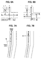
- a reference point of the pattern matching in the subsequent processing is generated on the center locus of the travelable area as a point that is determined as "most matching" for the travel locus with reference to the center locus (see FIGS. 7A and 7B ).
- the update of the pattern matching reference point may be performed for every 50 meters of vehicle travel, for example, or may be performed for every right/left turn. That is, the reference point update may be performed for a predetermined travel distance, or for every characteristic point in the travel locus.
- the update timing may be, naturally, a combination of the above criteria.
- a position estimated from the travel locus based on the calculation by using, as a start point, the latest pattern matching reference point is set as the estimated position of the vehicle.
- the relative locus and the center locus with reference to the reference point are available for a certain scope of map data, as shown in FIG. 8A
- the relative locus can be matched on the map with the center locus as shown in FIG. 8B . Therefore, the leading end of the relative locus is set as an estimated position 231 a.
- the travel locus accurately represents a traced shape of the vehicle travel for a short section of the vehicle travel, due to the smallness of errors.
- the absolute position derived from the GPS or the like may be used for the position estimation, as described in the explanation of S105.
- the control unit 39 then performs the candidate position update processing (S140).
- the candidate position update the estimated position of the vehicle calculated in S135 is used to determine a road point on the center locus. More practically, a point on the center locus closest to the estimated position is determined as the road point. Then, a position on the road link corresponding to the road point is determined as a new estimated position. In this manner, the current position candidate is sequentially updated time after time.
- FIG. 9A is an illustration of a pre-update state of the estimated position
- FIG. 9B is an illustration of a post-update state of the estimated position. That is, based on the pattern matching reference point (not shown in the illustration), an estimated position 232 is calculated from a travel locus 231. Then, the estimated position 232 is used to determine a road point 235 that is closest to the estimated position 232 on a center locus 234. Now, a position on the road link corresponding to the road point 235 is determined as a current position candidate after the update. The above procedure is performed for all of the current position candidates currently being set.
- the control unit 39 then performs the current position candidate evaluation processing (S145).
- the current position candidate evaluation based on the distance between the estimated position and the road point together with the road width, a departure distance of the estimated position from the travelable area is calculated, and the calculated departure distance is used to calculate the evaluation value for each of the current position candidates, for the purpose of certainty evaluation of the position candidates.
- the evaluation value may be calculated as a combinatorial value of the departure distance and (a) directional difference between the estimated travel direction and corresponding center locus, (b) positional/directional difference between the absolute position and the road point, or (c) other road shape related factors relative to the travel locus and/or the absolute position.
- the evaluation value may also be calculated as the average of the above-described value in a certain section of the road, or a total of (d) accumulated values and (e) latest momentary values weighted by some weighting factor
- the above equation may be differently formulated according to the considered factors in the evaluation scheme.
- the control unit 39 then performs the current position candidate deletion processing (S150).
- the candidates evaluated to have a lower possibility of correct current position relative to other candidates are deleted, based on the evaluation value calculated in S145.
- the deleted candidates are not processed in the subsequent processing.
- the determination of deletion of the candidates may be performed not only based on the evaluation value in S145, but also based on a combination of the evaluation value and other factors such as the positional different between the current position candidate and the absolute position or the like.
- the control unit 39 then performs the current position candidate selection processing (S155).
- the current position candidate that is to be output to the display unit 30 is selected based on the evaluation value of each of the candidates and preceding selection results.
- the candidate selection method may be based on:
- the current position candidate having the highest value is determined as the current position.
- the above selection method may be varied depending on the evaluation factors.
- the position of the selected candidate is output to the display unit 30 and displayed on the map by using an icon (S160).
- the icon on the previous position is deleted.
- the process performed by the control unit 39 is then returned to S105.
- the navigation apparatus 20 in the above embodiment is the same as the above embodiment:
- the navigation apparatus 20 in the above embodiment starts with the current position candidate (or the road link which has the current position candidate) to calculate and extend the road links to define the link series (i.e., the travelable path) in the travel path calculation processing (S125), to an extent of a predetermined distance, a predetermined number of links. Therefore, unnecessarily long link series is not defined.
- the relative travel distance and the relative directional change are calculated based on the signals from the gyroscope 23 and the distance sensor 24, relative to the previous cycle of processing. Then, the center locus of the travelable area is periodically updated based on the closeness to the travel locus of the vehicle. After travel locus update, the pattern matching reference point is set on the center locus for sequential update of the travel locus to calculate the estimated position of the vehicle (S135).
- the navigation apparatus 20 in the above embodiment determines the road point as a point on the center locus that is closest to the estimated position, and then uses the road point to find a corresponding point on the road link, for the purpose of determining the current position candidate after the update in the current position candidate update processing (S140). Therefore, in comparison to the method that does not use the road point determined in the above-described manner, the current position candidate can be more appropriately updated.
- the navigation apparatus 20 in the above embodiment can evaluate each of the current position candidates based on the distance between the estimated position of the vehicle and the travelable area in the current position candidate evaluation processing (S145), thereby enabling more appropriate evaluation of the current position candidates.
- the navigation apparatus 20 in the above embodiment deletes a current position candidate after selecting a relatively lower evaluation candidate, thereby suppressing the number of the current position candidate to an appropriate level and less demanding in terms of hardware resources.
- the absolute position detection processing (S105) corresponds to a function of a position information acquisition unit
- the estimated navigation processing (S110) corresponds to a function of a relative travel information acquisition unit and a locus calculation unit
- the map data input unit 29 corresponds to a road data acquisition unit.
- the current position candidate setting processing (S120) corresponds to a function of a candidate finding unit
- the travel path calculation processing (S125) corresponds to a function of a link series finding unit
- the center locus calculation processing (S130) corresponds to a function of a locus finding unit.
- the current position candidate update processing (S140) corresponds to a function of a position candidate update unit
- the estimate position calculation processing (S135) corresponds to a function of a travel position estimation unit
- the current position candidate evaluation processing (S145) corresponds to a function of an evaluation unit
- the current position candidate selection processing (S155) corresponds to a function of a current position finding unit
- the current position candidate deletion processing (S150) corresponds to a function of a current position candidate elimination unit.
- the navigation apparatus 20 prepares one or more of the current position candidates to select and display the most highly evaluated candidate as the current position on the map.
- the road links may be evaluated, without preparing the candidates, based on the distance from the absolute position detected in S105 (the absolute position detection processing) to the center locus of the corresponding link.
- the evaluation process of the above modification corresponds to a function of a travel position estimation unit, an evaluation unit, and a current position finding unit.
- the above modification of the embodiment can also yield, in comparison to the conventional navigation method that evaluates the current position directly from the road links, the more accurate current position of the vehicle, due to the fact that the center locus is closer to the actual vehicle position in comparison to the road links. Further, due to the novel and advantageous method of only using the line segments in the position calculation, the smaller memory area is required in the navigation apparatus 20 in comparison to the conventional method of using the polygon and apex coordinates for the position calculation. That is, in other words, the fewer hardware resources are required. Further, the position calculation itself is made simpler and quicker.
- the current position of the vehicle may be set on the link corresponding to the most matching center locus.
- the above processing corresponds to a function of a travel position estimation unit. The above processing yields the same advantageous results and the same advantageous effects as the above embodiment.
Landscapes
- Engineering & Computer Science (AREA)
- Radar, Positioning & Navigation (AREA)
- Remote Sensing (AREA)
- Automation & Control Theory (AREA)
- Physics & Mathematics (AREA)
- General Physics & Mathematics (AREA)
- Navigation (AREA)
- Traffic Control Systems (AREA)
- Instructional Devices (AREA)
Applications Claiming Priority (1)
| Application Number | Priority Date | Filing Date | Title |
|---|---|---|---|
| JP2008128294A JP4553033B2 (ja) | 2008-05-15 | 2008-05-15 | 現在位置算出装置及びプログラム |
Publications (3)
| Publication Number | Publication Date |
|---|---|
| EP2120015A2 true EP2120015A2 (fr) | 2009-11-18 |
| EP2120015A3 EP2120015A3 (fr) | 2011-10-19 |
| EP2120015B1 EP2120015B1 (fr) | 2017-02-22 |
Family
ID=40980208
Family Applications (1)
| Application Number | Title | Priority Date | Filing Date |
|---|---|---|---|
| EP09006491.6A Active EP2120015B1 (fr) | 2008-05-15 | 2009-05-13 | Appareil et programme pour trouver la position d'un véhicule |
Country Status (3)
| Country | Link |
|---|---|
| US (1) | US8180566B2 (fr) |
| EP (1) | EP2120015B1 (fr) |
| JP (1) | JP4553033B2 (fr) |
Cited By (5)
| Publication number | Priority date | Publication date | Assignee | Title |
|---|---|---|---|---|
| CN103256934A (zh) * | 2012-02-17 | 2013-08-21 | 株式会社电装 | 道路信息提供设备 |
| US10359290B2 (en) | 2013-03-22 | 2019-07-23 | Here Global B.V. | Method and apparatus for two dimensional edge-based map matching |
| CN111985662A (zh) * | 2020-06-30 | 2020-11-24 | 北京百度网讯科技有限公司 | 网络约车方法、装置、电子设备和存储介质 |
| EP3580524A4 (fr) * | 2017-02-07 | 2021-03-24 | Bayerische Motoren Werke Aktiengesellschaft | Procédé, dispositif et système de localisation d'un objet mobile |
| CN114676917A (zh) * | 2022-03-29 | 2022-06-28 | 福州大学 | 一种空驶出租汽车空间分布评估方法及系统 |
Families Citing this family (23)
| Publication number | Priority date | Publication date | Assignee | Title |
|---|---|---|---|---|
| WO2010030341A1 (fr) | 2008-09-09 | 2010-03-18 | United Parcel Service Of America, Inc. | Systèmes et procédés permettant d'utiliser des données télématiques, afin d'améliorer des opérations de gestion de flotte |
| US11482058B2 (en) | 2008-09-09 | 2022-10-25 | United Parcel Service Of America, Inc. | Systems and methods for utilizing telematics data to improve fleet management operations |
| JP5142047B2 (ja) * | 2009-02-26 | 2013-02-13 | アイシン・エィ・ダブリュ株式会社 | ナビゲーション装置及びナビゲーション用プログラム |
| JP5126263B2 (ja) * | 2010-03-23 | 2013-01-23 | 株式会社デンソー | 車両用ナビゲーション装置 |
| US9953468B2 (en) | 2011-03-31 | 2018-04-24 | United Parcel Service Of America, Inc. | Segmenting operational data |
| US9070100B2 (en) | 2011-03-31 | 2015-06-30 | United Parcel Service Of America, Inc. | Calculating speed and travel times with travel delays |
| US9208626B2 (en) | 2011-03-31 | 2015-12-08 | United Parcel Service Of America, Inc. | Systems and methods for segmenting operational data |
| US8543320B2 (en) * | 2011-05-19 | 2013-09-24 | Microsoft Corporation | Inferring a behavioral state of a vehicle |
| JP6054638B2 (ja) * | 2012-05-30 | 2016-12-27 | クラリオン株式会社 | 車両位置検出装置およびプログラム |
| JP6236954B2 (ja) * | 2013-07-23 | 2017-11-29 | アイシン・エィ・ダブリュ株式会社 | 運転支援システム、方法およびプログラム |
| JP5683664B2 (ja) * | 2013-10-08 | 2015-03-11 | 株式会社ゼンリンデータコム | 経路案内装置、経路案内方法及び経路案内プログラム |
| US9805521B1 (en) | 2013-12-03 | 2017-10-31 | United Parcel Service Of America, Inc. | Systems and methods for assessing turns made by a vehicle |
| US9746331B1 (en) * | 2014-12-15 | 2017-08-29 | Marvell International Ltd. | Method and apparatus for map matching |
| US20160334225A1 (en) * | 2015-05-11 | 2016-11-17 | United Parcel Service Of America, Inc. | Determining street segment headings |
| JP6972528B2 (ja) * | 2016-10-03 | 2021-11-24 | 日産自動車株式会社 | 自己位置推定方法、移動体の走行制御方法、自己位置推定装置、及び移動体の走行制御装置 |
| CN106781470B (zh) * | 2016-12-12 | 2022-01-28 | 百度在线网络技术(北京)有限公司 | 城市道路的运行速度的处理方法及装置 |
| JP6988450B2 (ja) * | 2017-12-22 | 2022-01-05 | 株式会社デンソー | 交差点内の走行軌道データ生成装置、交差点内の走行軌道データ生成プログラム及び記憶媒体 |
| JP7091670B2 (ja) * | 2018-01-18 | 2022-06-28 | 株式会社デンソー | 交差点内の走行軌道データ生成装置、交差点内の走行軌道データ生成プログラム及び記憶媒体 |
| CN110633597B (zh) * | 2018-06-21 | 2022-09-30 | 北京京东尚科信息技术有限公司 | 一种可行驶区域检测方法和装置 |
| JP7115246B2 (ja) * | 2018-11-21 | 2022-08-09 | 日本電信電話株式会社 | 現在位置推定装置、現在位置推定方法、及びプログラム |
| CN112556720B (zh) * | 2019-09-25 | 2023-08-18 | 上海汽车集团股份有限公司 | 一种车辆惯性导航校准方法、系统及车辆 |
| CN112990241B (zh) * | 2019-12-13 | 2023-08-25 | 百度在线网络技术(北京)有限公司 | 轨迹匹配方法、装置、设备及存储介质 |
| CN111260656B (zh) * | 2020-01-07 | 2023-07-25 | 北京百度网讯科技有限公司 | 分析导航轨迹的方法以及装置 |
Citations (2)
| Publication number | Priority date | Publication date | Assignee | Title |
|---|---|---|---|---|
| JPH02130415A (ja) | 1988-11-11 | 1990-05-18 | Honda Motor Co Ltd | 走行経路表示装置 |
| JPH10300492A (ja) | 1997-04-25 | 1998-11-13 | Mitsubishi Electric Corp | ロケータ装置 |
Family Cites Families (20)
| Publication number | Priority date | Publication date | Assignee | Title |
|---|---|---|---|---|
| US5060162A (en) * | 1988-12-09 | 1991-10-22 | Matsushita Electric Industrial Co., Ltd. | Vehicle in-situ locating apparatus |
| JP2783922B2 (ja) * | 1991-09-02 | 1998-08-06 | アルパイン株式会社 | 車両位置修正方法 |
| JPH06347278A (ja) * | 1993-06-10 | 1994-12-20 | Alpine Electron Inc | 車両の存在リンク検出方法 |
| JPH0868656A (ja) * | 1994-08-31 | 1996-03-12 | Alpine Electron Inc | 車載用ナビゲーション装置 |
| JPH11232583A (ja) * | 1998-02-12 | 1999-08-27 | Mitsubishi Electric Corp | 交通シミュレーション・システム |
| US6581005B2 (en) * | 2000-11-30 | 2003-06-17 | Nissan Motor Co., Ltd. | Vehicle position calculation apparatus and method |
| JP2003121180A (ja) * | 2001-10-15 | 2003-04-23 | Alpine Electronics Inc | 車両位置検出装置 |
| JP4003827B2 (ja) * | 2002-03-27 | 2007-11-07 | 富士通エフ・アイ・ピー株式会社 | 交通量感知器を用いた路面性状推定方法とシステム |
| JP2003067883A (ja) * | 2002-06-10 | 2003-03-07 | Hitachi Ltd | 広域道路交通空間における交通状況の予測方法 |
| JP2004226341A (ja) | 2003-01-27 | 2004-08-12 | Alpine Electronics Inc | マップマッチング方法 |
| JP3945444B2 (ja) * | 2003-04-08 | 2007-07-18 | 株式会社デンソー | カーナビゲーション装置 |
| JP2005207821A (ja) * | 2004-01-21 | 2005-08-04 | Alpine Electronics Inc | ナビゲーション装置における車両位置のマップマッチング方式 |
| JP2007078519A (ja) * | 2005-09-14 | 2007-03-29 | Nissan Motor Co Ltd | 車載ナビゲーション装置及びマップマッチング方法 |
| JP4832903B2 (ja) * | 2006-01-17 | 2011-12-07 | アルパイン株式会社 | ナビゲーション装置及び現在位置算定方法 |
| JP2008014666A (ja) * | 2006-07-03 | 2008-01-24 | Nec Corp | マップマッチングに適するリンク設定システム、その方法およびプログラム |
| JP2008026032A (ja) * | 2006-07-18 | 2008-02-07 | Denso Corp | 車両用ナビゲーション装置 |
| JP4829711B2 (ja) * | 2006-07-28 | 2011-12-07 | アルパイン株式会社 | 車載用ナビゲーション装置及び自車位置修正方法 |
| JP4953829B2 (ja) | 2007-01-11 | 2012-06-13 | アルパイン株式会社 | ナビゲーション装置および自車位置決定方法 |
| US20100121518A1 (en) * | 2008-11-11 | 2010-05-13 | Timothy Arthur Tiernan | Map enhanced positioning sensor system |
| JP5554045B2 (ja) * | 2009-10-21 | 2014-07-23 | アルパイン株式会社 | 地図表示装置及び地図表示方法 |
-
2008
- 2008-05-15 JP JP2008128294A patent/JP4553033B2/ja not_active Expired - Fee Related
-
2009
- 2009-05-13 EP EP09006491.6A patent/EP2120015B1/fr active Active
- 2009-05-14 US US12/453,567 patent/US8180566B2/en not_active Expired - Fee Related
Patent Citations (2)
| Publication number | Priority date | Publication date | Assignee | Title |
|---|---|---|---|---|
| JPH02130415A (ja) | 1988-11-11 | 1990-05-18 | Honda Motor Co Ltd | 走行経路表示装置 |
| JPH10300492A (ja) | 1997-04-25 | 1998-11-13 | Mitsubishi Electric Corp | ロケータ装置 |
Cited By (7)
| Publication number | Priority date | Publication date | Assignee | Title |
|---|---|---|---|---|
| CN103256934A (zh) * | 2012-02-17 | 2013-08-21 | 株式会社电装 | 道路信息提供设备 |
| CN103256934B (zh) * | 2012-02-17 | 2016-09-28 | 株式会社电装 | 道路信息提供设备 |
| US10359290B2 (en) | 2013-03-22 | 2019-07-23 | Here Global B.V. | Method and apparatus for two dimensional edge-based map matching |
| EP3580524A4 (fr) * | 2017-02-07 | 2021-03-24 | Bayerische Motoren Werke Aktiengesellschaft | Procédé, dispositif et système de localisation d'un objet mobile |
| CN111985662A (zh) * | 2020-06-30 | 2020-11-24 | 北京百度网讯科技有限公司 | 网络约车方法、装置、电子设备和存储介质 |
| CN111985662B (zh) * | 2020-06-30 | 2024-01-12 | 北京百度网讯科技有限公司 | 网络约车方法、装置、电子设备和存储介质 |
| CN114676917A (zh) * | 2022-03-29 | 2022-06-28 | 福州大学 | 一种空驶出租汽车空间分布评估方法及系统 |
Also Published As
| Publication number | Publication date |
|---|---|
| US20090287410A1 (en) | 2009-11-19 |
| JP4553033B2 (ja) | 2010-09-29 |
| US8180566B2 (en) | 2012-05-15 |
| EP2120015B1 (fr) | 2017-02-22 |
| EP2120015A3 (fr) | 2011-10-19 |
| JP2009276224A (ja) | 2009-11-26 |
Similar Documents
| Publication | Publication Date | Title |
|---|---|---|
| EP2120015B1 (fr) | Appareil et programme pour trouver la position d'un véhicule | |
| EP3654235A1 (fr) | Procédé et appareil de détermination de ligne de route | |
| EP2255349B1 (fr) | Dispositif d'aide à la conduite, procédé d'aide à la conduite et programme d'aide à la conduite | |
| JP4899351B2 (ja) | 走行状況判定装置及び車載ナビゲーション装置 | |
| EP2533012B1 (fr) | Système de navigation comprenant un appareil d'estimation de destination | |
| EP3203187B1 (fr) | Système de navigation et dispositif central | |
| JP6472355B2 (ja) | ナビサーバ、ナビクライアントおよびナビ方法 | |
| JP4950494B2 (ja) | 走行車線推定装置及び走行車線推定方法 | |
| WO2015145819A1 (fr) | Système, procédé et programme de génération d'informations cartographiques | |
| WO2019203084A1 (fr) | Système de mise à jour d'informations cartographiques et programme de mise à jour d'informations cartographiques | |
| JP2009025178A (ja) | ナビゲーション装置、及びナビゲーション用プログラム | |
| JP5932531B2 (ja) | 電子機器、目的地探索方法、プログラム、記録媒体、ナビゲーションシステム、およびサーバ装置 | |
| JP2022176322A (ja) | 自己位置推定装置、制御方法、プログラム及び記憶媒体 | |
| CN104422449B (zh) | 一种车辆导航的方法、装置 | |
| WO2019189098A1 (fr) | Dispositif d'estimation de position automatique, procédé d'estimation de position automatique, programme et support d'enregistrement | |
| KR101325145B1 (ko) | 이동 로봇의 길 지도를 이용한 경로 탐색 장치 및 방법 | |
| JP2544855B2 (ja) | 車両誘導装置 | |
| JP5276922B2 (ja) | 現在位置算出装置 | |
| US20040204839A1 (en) | Navigation method and system for large compound | |
| JP2023078138A (ja) | 出力装置、制御方法、プログラム及び記憶媒体 | |
| JP2009014555A (ja) | ナビゲーション装置、ナビゲーション方法及びナビゲーションプログラム | |
| KR20140132959A (ko) | 누적 헤딩 변화량을 이용한 맵매칭 시스템 및 방법 | |
| WO2019188877A1 (fr) | Dispositif de transmission d'informations, structure de données, procédé de commande, programme et support de stockage | |
| CN104956181A (zh) | 导航系统、方法以及程序 | |
| JP3432812B2 (ja) | 車両用道路関連情報事前提示装置 |
Legal Events
| Date | Code | Title | Description |
|---|---|---|---|
| PUAI | Public reference made under article 153(3) epc to a published international application that has entered the european phase |
Free format text: ORIGINAL CODE: 0009012 |
|
| AK | Designated contracting states |
Kind code of ref document: A2 Designated state(s): AT BE BG CH CY CZ DE DK EE ES FI FR GB GR HR HU IE IS IT LI LT LU LV MC MK MT NL NO PL PT RO SE SI SK TR |
|
| PUAL | Search report despatched |
Free format text: ORIGINAL CODE: 0009013 |
|
| AK | Designated contracting states |
Kind code of ref document: A3 Designated state(s): AT BE BG CH CY CZ DE DK EE ES FI FR GB GR HR HU IE IS IT LI LT LU LV MC MK MT NL NO PL PT RO SE SI SK TR |
|
| AX | Request for extension of the european patent |
Extension state: AL BA RS |
|
| RIC1 | Information provided on ipc code assigned before grant |
Ipc: G01C 21/30 20060101AFI20110915BHEP |
|
| 17P | Request for examination filed |
Effective date: 20120419 |
|
| GRAP | Despatch of communication of intention to grant a patent |
Free format text: ORIGINAL CODE: EPIDOSNIGR1 |
|
| INTG | Intention to grant announced |
Effective date: 20160803 |
|
| GRAS | Grant fee paid |
Free format text: ORIGINAL CODE: EPIDOSNIGR3 |
|
| GRAJ | Information related to disapproval of communication of intention to grant by the applicant or resumption of examination proceedings by the epo deleted |
Free format text: ORIGINAL CODE: EPIDOSDIGR1 |
|
| GRAL | Information related to payment of fee for publishing/printing deleted |
Free format text: ORIGINAL CODE: EPIDOSDIGR3 |
|
| GRAR | Information related to intention to grant a patent recorded |
Free format text: ORIGINAL CODE: EPIDOSNIGR71 |
|
| GRAA | (expected) grant |
Free format text: ORIGINAL CODE: 0009210 |
|
| INTC | Intention to grant announced (deleted) | ||
| AK | Designated contracting states |
Kind code of ref document: B1 Designated state(s): AT BE BG CH CY CZ DE DK EE ES FI FR GB GR HR HU IE IS IT LI LT LU LV MC MK MT NL NO PL PT RO SE SI SK TR |
|
| INTG | Intention to grant announced |
Effective date: 20170116 |
|
| REG | Reference to a national code |
Ref country code: GB Ref legal event code: FG4D |
|
| REG | Reference to a national code |
Ref country code: CH Ref legal event code: EP |
|
| REG | Reference to a national code |
Ref country code: AT Ref legal event code: REF Ref document number: 869594 Country of ref document: AT Kind code of ref document: T Effective date: 20170315 |
|
| REG | Reference to a national code |
Ref country code: IE Ref legal event code: FG4D |
|
| REG | Reference to a national code |
Ref country code: DE Ref legal event code: R096 Ref document number: 602009044277 Country of ref document: DE |
|
| REG | Reference to a national code |
Ref country code: FR Ref legal event code: PLFP Year of fee payment: 9 |
|
| REG | Reference to a national code |
Ref country code: LT Ref legal event code: MG4D |
|
| REG | Reference to a national code |
Ref country code: NL Ref legal event code: MP Effective date: 20170222 |
|
| REG | Reference to a national code |
Ref country code: AT Ref legal event code: MK05 Ref document number: 869594 Country of ref document: AT Kind code of ref document: T Effective date: 20170222 |
|
| PG25 | Lapsed in a contracting state [announced via postgrant information from national office to epo] |
Ref country code: FI Free format text: LAPSE BECAUSE OF FAILURE TO SUBMIT A TRANSLATION OF THE DESCRIPTION OR TO PAY THE FEE WITHIN THE PRESCRIBED TIME-LIMIT Effective date: 20170222 Ref country code: LT Free format text: LAPSE BECAUSE OF FAILURE TO SUBMIT A TRANSLATION OF THE DESCRIPTION OR TO PAY THE FEE WITHIN THE PRESCRIBED TIME-LIMIT Effective date: 20170222 Ref country code: HR Free format text: LAPSE BECAUSE OF FAILURE TO SUBMIT A TRANSLATION OF THE DESCRIPTION OR TO PAY THE FEE WITHIN THE PRESCRIBED TIME-LIMIT Effective date: 20170222 Ref country code: GR Free format text: LAPSE BECAUSE OF FAILURE TO SUBMIT A TRANSLATION OF THE DESCRIPTION OR TO PAY THE FEE WITHIN THE PRESCRIBED TIME-LIMIT Effective date: 20170523 Ref country code: NO Free format text: LAPSE BECAUSE OF FAILURE TO SUBMIT A TRANSLATION OF THE DESCRIPTION OR TO PAY THE FEE WITHIN THE PRESCRIBED TIME-LIMIT Effective date: 20170522 |
|
| PG25 | Lapsed in a contracting state [announced via postgrant information from national office to epo] |
Ref country code: ES Free format text: LAPSE BECAUSE OF FAILURE TO SUBMIT A TRANSLATION OF THE DESCRIPTION OR TO PAY THE FEE WITHIN THE PRESCRIBED TIME-LIMIT Effective date: 20170222 Ref country code: LV Free format text: LAPSE BECAUSE OF FAILURE TO SUBMIT A TRANSLATION OF THE DESCRIPTION OR TO PAY THE FEE WITHIN THE PRESCRIBED TIME-LIMIT Effective date: 20170222 Ref country code: PT Free format text: LAPSE BECAUSE OF FAILURE TO SUBMIT A TRANSLATION OF THE DESCRIPTION OR TO PAY THE FEE WITHIN THE PRESCRIBED TIME-LIMIT Effective date: 20170622 Ref country code: LU Free format text: LAPSE BECAUSE OF NON-PAYMENT OF DUE FEES Effective date: 20170531 Ref country code: NL Free format text: LAPSE BECAUSE OF FAILURE TO SUBMIT A TRANSLATION OF THE DESCRIPTION OR TO PAY THE FEE WITHIN THE PRESCRIBED TIME-LIMIT Effective date: 20170222 Ref country code: BG Free format text: LAPSE BECAUSE OF FAILURE TO SUBMIT A TRANSLATION OF THE DESCRIPTION OR TO PAY THE FEE WITHIN THE PRESCRIBED TIME-LIMIT Effective date: 20170522 Ref country code: SE Free format text: LAPSE BECAUSE OF FAILURE TO SUBMIT A TRANSLATION OF THE DESCRIPTION OR TO PAY THE FEE WITHIN THE PRESCRIBED TIME-LIMIT Effective date: 20170222 Ref country code: AT Free format text: LAPSE BECAUSE OF FAILURE TO SUBMIT A TRANSLATION OF THE DESCRIPTION OR TO PAY THE FEE WITHIN THE PRESCRIBED TIME-LIMIT Effective date: 20170222 |
|
| PG25 | Lapsed in a contracting state [announced via postgrant information from national office to epo] |
Ref country code: RO Free format text: LAPSE BECAUSE OF FAILURE TO SUBMIT A TRANSLATION OF THE DESCRIPTION OR TO PAY THE FEE WITHIN THE PRESCRIBED TIME-LIMIT Effective date: 20170222 Ref country code: CZ Free format text: LAPSE BECAUSE OF FAILURE TO SUBMIT A TRANSLATION OF THE DESCRIPTION OR TO PAY THE FEE WITHIN THE PRESCRIBED TIME-LIMIT Effective date: 20170222 Ref country code: SK Free format text: LAPSE BECAUSE OF FAILURE TO SUBMIT A TRANSLATION OF THE DESCRIPTION OR TO PAY THE FEE WITHIN THE PRESCRIBED TIME-LIMIT Effective date: 20170222 Ref country code: EE Free format text: LAPSE BECAUSE OF FAILURE TO SUBMIT A TRANSLATION OF THE DESCRIPTION OR TO PAY THE FEE WITHIN THE PRESCRIBED TIME-LIMIT Effective date: 20170222 Ref country code: IT Free format text: LAPSE BECAUSE OF FAILURE TO SUBMIT A TRANSLATION OF THE DESCRIPTION OR TO PAY THE FEE WITHIN THE PRESCRIBED TIME-LIMIT Effective date: 20170222 |
|
| REG | Reference to a national code |
Ref country code: DE Ref legal event code: R097 Ref document number: 602009044277 Country of ref document: DE |
|
| PG25 | Lapsed in a contracting state [announced via postgrant information from national office to epo] |
Ref country code: PL Free format text: LAPSE BECAUSE OF FAILURE TO SUBMIT A TRANSLATION OF THE DESCRIPTION OR TO PAY THE FEE WITHIN THE PRESCRIBED TIME-LIMIT Effective date: 20170222 Ref country code: DK Free format text: LAPSE BECAUSE OF FAILURE TO SUBMIT A TRANSLATION OF THE DESCRIPTION OR TO PAY THE FEE WITHIN THE PRESCRIBED TIME-LIMIT Effective date: 20170222 |
|
| PLBE | No opposition filed within time limit |
Free format text: ORIGINAL CODE: 0009261 |
|
| REG | Reference to a national code |
Ref country code: CH Ref legal event code: PL |
|
| STAA | Information on the status of an ep patent application or granted ep patent |
Free format text: STATUS: NO OPPOSITION FILED WITHIN TIME LIMIT |
|
| GBPC | Gb: european patent ceased through non-payment of renewal fee |
Effective date: 20170522 |
|
| 26N | No opposition filed |
Effective date: 20171123 |
|
| PG25 | Lapsed in a contracting state [announced via postgrant information from national office to epo] |
Ref country code: MC Free format text: LAPSE BECAUSE OF FAILURE TO SUBMIT A TRANSLATION OF THE DESCRIPTION OR TO PAY THE FEE WITHIN THE PRESCRIBED TIME-LIMIT Effective date: 20170222 |
|
| REG | Reference to a national code |
Ref country code: IE Ref legal event code: MM4A |
|
| PG25 | Lapsed in a contracting state [announced via postgrant information from national office to epo] |
Ref country code: LI Free format text: LAPSE BECAUSE OF NON-PAYMENT OF DUE FEES Effective date: 20170531 Ref country code: CH Free format text: LAPSE BECAUSE OF NON-PAYMENT OF DUE FEES Effective date: 20170531 Ref country code: SI Free format text: LAPSE BECAUSE OF FAILURE TO SUBMIT A TRANSLATION OF THE DESCRIPTION OR TO PAY THE FEE WITHIN THE PRESCRIBED TIME-LIMIT Effective date: 20170222 |
|
| PG25 | Lapsed in a contracting state [announced via postgrant information from national office to epo] |
Ref country code: LU Free format text: LAPSE BECAUSE OF NON-PAYMENT OF DUE FEES Effective date: 20170513 |
|
| REG | Reference to a national code |
Ref country code: BE Ref legal event code: MM Effective date: 20170531 |
|
| PG25 | Lapsed in a contracting state [announced via postgrant information from national office to epo] |
Ref country code: IE Free format text: LAPSE BECAUSE OF NON-PAYMENT OF DUE FEES Effective date: 20170513 Ref country code: GB Free format text: LAPSE BECAUSE OF NON-PAYMENT OF DUE FEES Effective date: 20170522 |
|
| REG | Reference to a national code |
Ref country code: FR Ref legal event code: PLFP Year of fee payment: 10 |
|
| PG25 | Lapsed in a contracting state [announced via postgrant information from national office to epo] |
Ref country code: BE Free format text: LAPSE BECAUSE OF NON-PAYMENT OF DUE FEES Effective date: 20170531 |
|
| PG25 | Lapsed in a contracting state [announced via postgrant information from national office to epo] |
Ref country code: MT Free format text: LAPSE BECAUSE OF NON-PAYMENT OF DUE FEES Effective date: 20170513 |
|
| PG25 | Lapsed in a contracting state [announced via postgrant information from national office to epo] |
Ref country code: HU Free format text: LAPSE BECAUSE OF FAILURE TO SUBMIT A TRANSLATION OF THE DESCRIPTION OR TO PAY THE FEE WITHIN THE PRESCRIBED TIME-LIMIT; INVALID AB INITIO Effective date: 20090513 |
|
| PG25 | Lapsed in a contracting state [announced via postgrant information from national office to epo] |
Ref country code: CY Free format text: LAPSE BECAUSE OF NON-PAYMENT OF DUE FEES Effective date: 20170222 |
|
| PG25 | Lapsed in a contracting state [announced via postgrant information from national office to epo] |
Ref country code: MK Free format text: LAPSE BECAUSE OF FAILURE TO SUBMIT A TRANSLATION OF THE DESCRIPTION OR TO PAY THE FEE WITHIN THE PRESCRIBED TIME-LIMIT Effective date: 20170222 |
|
| PG25 | Lapsed in a contracting state [announced via postgrant information from national office to epo] |
Ref country code: TR Free format text: LAPSE BECAUSE OF FAILURE TO SUBMIT A TRANSLATION OF THE DESCRIPTION OR TO PAY THE FEE WITHIN THE PRESCRIBED TIME-LIMIT Effective date: 20170222 |
|
| PG25 | Lapsed in a contracting state [announced via postgrant information from national office to epo] |
Ref country code: IS Free format text: LAPSE BECAUSE OF FAILURE TO SUBMIT A TRANSLATION OF THE DESCRIPTION OR TO PAY THE FEE WITHIN THE PRESCRIBED TIME-LIMIT Effective date: 20170622 |
|
| PGFP | Annual fee paid to national office [announced via postgrant information from national office to epo] |
Ref country code: FR Payment date: 20230525 Year of fee payment: 15 Ref country code: DE Payment date: 20230519 Year of fee payment: 15 |