EP2119634B1 - Bündelauspackmaschine - Google Patents
Bündelauspackmaschine Download PDFInfo
- Publication number
- EP2119634B1 EP2119634B1 EP09160481.9A EP09160481A EP2119634B1 EP 2119634 B1 EP2119634 B1 EP 2119634B1 EP 09160481 A EP09160481 A EP 09160481A EP 2119634 B1 EP2119634 B1 EP 2119634B1
- Authority
- EP
- European Patent Office
- Prior art keywords
- plastic
- blade
- bundle
- wrapping
- machine
- Prior art date
- Legal status (The legal status is an assumption and is not a legal conclusion. Google has not performed a legal analysis and makes no representation as to the accuracy of the status listed.)
- Not-in-force
Links
Images


Classifications
-
- B—PERFORMING OPERATIONS; TRANSPORTING
- B65—CONVEYING; PACKING; STORING; HANDLING THIN OR FILAMENTARY MATERIAL
- B65B—MACHINES, APPARATUS OR DEVICES FOR, OR METHODS OF, PACKAGING ARTICLES OR MATERIALS; UNPACKING
- B65B69/00—Unpacking of articles or materials, not otherwise provided for
- B65B69/0033—Unpacking of articles or materials, not otherwise provided for by cutting
Definitions
- the invention relates to systems for the automated opening of packages such as shrink wrapped bundles of flat mail pieces.
- a method of preparing flat articles for sorting includes the steps of: (1) receiving a bundle of flat items to be sorted, the bundle being wrapped with a flexible film such that the film forms an enclosed package of flat items, (2) placing the bundles on a substantially horizontal, substantially frictionless work surface, moving the bundle adjacent at least one film opener, the film opener being automatically activated when the bundle is moved adjacent the film opener, (3) removing the cut film from the flat items, and (4) stacking the unbundled flat items in a cartridge.
- Document WO-A-94/11254 discloses a device for automated cutting and removing of foil-like wrappers from a bundle of flat articles.
- the present invention provides a method and apparatus for automatic bundle transport, positioning, wrapper entry, wrapper opening, wrapper loosening, wrapper removal, and wrapper dunnage takeaway.
- the wrapper is made from pliable material, thin film or similar material and which can comprise a variety of package types and sizes of mail, media or other items. Additionally the method and apparatus of the invention performs the tasks of wrapper removal and discharge without damaging the item contents within.
- a bundle unwrapping machine according to the invention includes a conveyor by which bundles are presented to the unwrapping machine for opening.
- An opening mechanism includes a pair of openers positioned to engage a bundle on opposite sites. The bundle is transported into an opening zone in which it is supported for engagement with the openers.
- a machine for removing plastic wrapping from a bundle of flat articles wrapped in plastic includes a conveyor for transporting a wrapped bundle through the machine, a first blade assembly including a pointed blade mounted on a holder provided with a mechanical actuator that slides the blade point first along the surface of the outer face of the bundle, such that the point of the blade pierces the plastic causing the blade to move beneath the plastic wrapping while sliding along the outer surface of one of the flat articles without damaging it, and the blade stretches and tears the plastic as it continues to move beneath the plastic wrapping; and an automated removal and disposal system which separates the torn plastic from the flat articles.
- a vacuum system includes a vacuum head that applies suction to an outer face of the bundle, drawing the plastic film towards the vacuum head and creating a bulge in the plastic wrap which the blade is positioned to pierce.
- An automated method for removing plastic wrapping from a bundle of flat articles wrapped in plastic or similar sheet material comprises transporting a wrapped bundle on a conveyor into an automated unwrapping machine.
- the machine slides a first blade assembly including a pointed blade mounted on a holder point first along the surface of the outer face of the bundle, such that the point of the blade pierces the plastic causing the blade to move beneath the plastic wrapping while sliding along the outer surface of one of the flat articles without damaging it.
- a wrapper or wrapping according to the invention can be shrink wrap or a bag that encloses the articles completely, but could also be a less than complete covering such as a band.
- Plastic is the most common material for the wrapper, but paper or other similar material could be used.
- a bundle unwrapping machine 10 includes a number of moving parts, many of which are arranged in pairs for simultaneous coordinated movement.
- basic actuation components include linear actuators in the form of electric solenoids with extendable rods that are connected to the part to be moved by extension or retraction of the solenoid.
- the moving parts can be provided with proximity or contact sensors connected to the control system. In some cases a spring may be sufficient to bias the part in the desired position. Examples of these actuation systems are discussed further below.
- the control system could be a computer or PLC programmed to carry out the steps as described hereafter.
- the system may or may not need to be reprogrammed for bundles of different types and sizes, or can be provided with sensors that tell the control system process parameters to use.
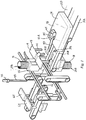
- a bundle unwrapping machine 10 includes a pair of horizontal, parallel spaced belt conveyors 12A for transporting a plastic wrapped bundle 14.
- a second pair of conveyors 12B accept bundle 14 from conveyors 12A and take it further into machine 10 as described below.
- Bundle 14 is typically flat on opposite top and bottom faces and most often rectangular in shape. It comprises a stack of magazines, catalogues or the like wrapped with a thin plastic film on all sides.
- bundles 14 are removed from a pallet and placed on a roller conveyor for manual inspection. Exception bundles such as ones damaged in transit are removed for manual opening.
- Bundles 14 suitable for automated opening are placed one at a time on conveyors 12A centred in the widthwise direction so that the underside of the bundle 14 can be accessed from below through the gaps between conveyors 12A, and between conveyors 12B.
- one or more retractable stop gates 16 are moved into position to stop bundle 14 at a desired forward position for opening.
- Each gate 16 in this example pivots into and out of position by means of a pivotably mounted linear actuator 17 as shown in Fig. 1A .
- gates 16 could also be configured to rise and drop vertically.
- One or more grippers 18 are provided to grip the trailing end of bundle 14 once it engages gates 16.
- Grippers 18 are L-shaped brackets with an upper horizontal beam 19 and one or more downwardly depending arms or flanges 21. Each gripper 18 is raised or lowered by means of a first linear actuator 17A, and the assembly of gripper 18 and actuator 17A can be moved horizontally by a second linear actuator 17B ( Fig. 1 B) .
- Grippers 18 start in the up position so that bundle 14 can pass beneath them, are lowered using actuator 17A, then drawn forward by actuator 17B so that fingers 21 engage the rear end of bundle 14. Complete engagement can be detected by means of a pressure sensor 22 that tells the control system that the bundle 14 has been firmly held between gates 16 in front and grippers 18 behind.
- a vacuum assembly 24A is suspended above the mid-portion of machine 10 and is preferably centred on bundle 14. Assembly 24A may be raised and lowered by any suitable means, such as a linear actuator or an electric pulley operated by the control system.
- An inverted U-shaped rectangular frame 26 retains a hose 27 which extends through an opening in its top wall. Frame 26 provides a pair of control pads 28 on opposite sides of its bottom edge that move down ahead of a central vacuum head 29 at the end of hose 27. Pads 28 move into engagement with the upper surface of the bundle 14 before suction is applied, and optionally may be biased by a coil spring 31 that exerts force against the upper surface of frame 26.
- This engagement acts to control the differential deflection range of the plastic film relative to the surface of the underlying article once vacuum head 29 exerts suction against the plastic beneath it on the upper side of bundle 14.
- Differential deflection refers to the difference between the distance the plastic deflects under suction as compared to the distance the underlying item deflects. Unless a sufficient differential is maintained, the first page of the top item of the bundle contents will be pulled up by the suction along with the plastic wrap. Heating as described below helps avoid this problem.
- suction from vacuum head 29A causes the plastic wrap to deflect upwardly, creating an upwardly extending bulge in the plastic covering that is positioned for piercing.
- vacuum head 29A may be lowered into contract with the top of bundle 14 and then raised a short distance once vacuum has been applied.
- a lower vacuum head 29B of a second vacuum assembly 24B engages the underside of bundle 14 in the same manner and is actuated at the same time and controlled in the same manner but in reverse orientation.
- heat is applied to the area of the plastic wrap that the vacuum head is about to engage.
- a stream of forced air is suitable, which air is heated to a temperature sufficient to soften the plastic wrap without damage to the underlying contents. This may be done manually or automatically.
- a temperature of up to 150°F is usually suitable, causing the plastic wrap to deflect more than the paper of an underlying page or magazine cover. The vacuum aids this process because it draws the heated air directly to the site where the bulge is to be created.
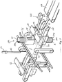
- assemblies 32 are each configured for horizontal and vertical movement and may be essentially identical although reverse in orientation relative to each other.
- Each assembly 32 includes a plastic blade 33 with a pointed tip 34 but lacking a sharp side cutting edge.
- Blades 33 are made of a smooth surfaced moulded plastic, although other materials could be used, including metal. Plastic however is preferred because it is less likely to catch on and damage the contents of the bundle under the plastic wrap.
- Blades 33 are mounted to extend forwardly, flat, slightly rounded side down, from a tang or mounting block 35 that also can be made of plastic.
- the blade assemblies 32A, 32B each include a vertical linear actuator 36 and a horizontal linear actuator 37.
- the plunger of actuator 37 is connected to block 35 so that operation of actuator 37 extends or retracts blade 33.
- a frame 38 connects actuator 37 to the operative end (plunger) of actuator 36. By this means extension or retraction of actuator 36 raises or lowers the assembly of blade 33, block 35, actuator 37 and frame 38.
- proximity or contact sensors can be provided to prevent over-extension of the actuators 36 and 37; or the cycle timing may be used to control these actuators.
- vacuum head 29A moves into proximity to the upper surface of bundle 14, the suction is sufficient to stretch and hold the underlying plastic wrap.
- a similar event takes place in the underside of bundle 14 using the bottom vacuum head 29B.
- Some bundle types have voids therein on the top and bottom that the blades 33 of the invention can readily penetrate, and for bundles of this kind, vacuum assemblies 24A, 24B need not be used.
- Figure 2 shows the bundle 14 in position for piercing the plastic wrap before the blade assemblies start to advance.
- Both sets of actuators 36 and 37 are then actuated so that blades 33A and 33B move to the correct vertical position relative to the bulges created in the plastic wrap, and the blades 33A, 33B advance simultaneously towards the upper and lower bulges 40.
- Points 34 of the blades readily pierce the plastic wrap and slide along the surface of the topmost flat item in bundle 14, such as a magazine.
- the speed of movement of blades 33A, 32B is preferably slow enough to minimize the likelihood of damage to the bundle contents, for example from 0.1 m/sec to 10 m/sec, preferably 0.5 m/sec to 2 m/sec.
- Figure 2 shows the bundle 14 in position for piercing the plastic wrap before the blade assemblies start to advance. This operation may be timed and preprogrammed based on the known length of bundles 14, or based on the horizontal spacing, between stop gate 16 and grippers 18.
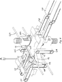
- FIG. 3 shows blades 33A, 33B at the front edge of bundle 14, which has now been partially torn open on top and bottom.
- the plastic wrap 41 has gathered at the front of block 35 and is stretched away from the contents of the bundle 14. Block 35 has moved into position below a vertical opener 42.
- Opener 42 includes a pin 43 that is lowered by a linear actuator thorough a hole 44 in block 35. With pin 43 extended through the stretched film at a position in front of the bundle contents, block 35 of blade 33A is then driven further forward by its horizontal actuator 37 carrying pin 43 with it. For this purpose it may be useful to use a hold-and-release style of robotic vertical actuator for openers 42 that grips, moves and then releases the head of pin 43.
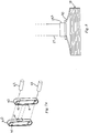
- an unwrapping system 50 includes two pairs of parallel rods 52A, 52B above and 52C, 52D below the position where bundle 14 is supported on second conveyors 12B.
- rods 52 each end in a horizontally extending curved finger 53.
- Finger 53 of rod 52A is mounted on the end of rod 52A by means of a holder 54 and extends to the left in Fig. 4 from the left side of machine 10.
- Holders 54 are preferably spring-loaded to hold the fingers 53 lightly against the surface of the underlying article.
- Finger 53 of upper rod 52B is offset horizontally a short distance from rod 52A and extends to the right in Fig. 4 from the right side of machine 10.
- Finger 53 of lower rod 52C extends in the same direction as finger 53 of rod 52A, and finger 53 of lower rod 52D extends in the same direction as finger 53 of rod 52B.
- Linear actuators for moving rods 52 are at the ends opposite to the fingers 53.
- rods 52 move to the positions shown in Fig. 5 so that a pair of fingers 53 is positioned side-by-side facing in opposite directions above bundle 14 as shown, and below bundle 14 in the same manner.
- the curved ends of fingers 53 preferably present a convex outer surface that aids fingers 53 in sliding under the open edges 55 of the wrap 41.
- Rods 52 are then actuated so that they assume the position shown in Fig. 6 .
- Fingers 53 pull edges 55 in opposite directions on both the top and bottom of bundle 14. By this means forward side portions 56 of wrap 41 are pulled outwardly both right and left in Fig. 6 .
- pairs of driven vertical belts 60 such as timing belts are provided on the left and right sides of machine 10.
- Each belt has a gripping pad 61 on its outer surface.
- Belts 60 are arranged in opposing pairs with gripping pads 61 in opposing positions.
- the left side front belt 60A faces left side rear belt 60B, and the same is true of belts 60C and 60D on the right.
- Belts 60 are spaced from each other initially but must move together at the appropriate time so that pads 61 of each pair 60A, 60B and 60C, 60D come close to one another as shown in Fig. 7 .
- One or both belts 60 of a pair can move for this purpose.
- belts 60 of each pair can be driven by any suitable means such as power rollers 62.
- At least one belt is provided with one or more linear actuators 63 for moving the belt assembly horizontally so that its pad 61 comes close to the pad 61 of the belt 60 facing it.
- wrap 41 is gripped on both sides by two pairs of pads 61.
- a pair of underlying forward belt conveyors12C similar to conveyors 12B move the contents 70 of bundle 14 forward into contact with a stop or stops 65 at the front end of machine 10. Wrap 41 held on both sides by pairs of pads 61 is removed from contents 70 as contents 70 moves forward. Once stop 65 is contacted, it is possible then to drive each of belts 60 in tandem with each other so that pads 61 move out of contact by passing around the next belt pulley, allowing wrap 41 to drop free into a collection container beneath machine 10. Contents 70 can then be removed manually or continue to be conveyed on an extension of conveyor 12C upon removal of stop 65.
- Actuators 36, 37 are used to return blades 33A, 33B to their starting positions when the tearing stroke is completed.
- the described system thus provides for fully automated unwrapping of a plastic wrapped bundle of flat items such as magazines, catalogues or the like.
- the system of the invention does not use knives or cutting blades to open packaging.
- the blades of the present invention are configured to pierce the plastic film with a thrusting motion, not cut it along a line with a sharp edge or the like.
- the latter approach is not suitable for automated opening of plastic wrapped bundles of flat mail which could be easily damaged by a metal knife or razor blade.
- both upper and lower drive belts can be provided which clamp the bundle.
- the throat of the upper/lower drive belts can be configured to spread to a distance adequate to accept various wrapped bundle heights.
- Position and dimension sensors may be deployed as needed so that a computerized control system can adjust the positions of moving parts to accommodate bundles of different sizes. Detectors such as photocells can be used to indicate when the bundle has reached a position at which a further operation should begin.
- the vacuum system may be provided with a valve for turning suction off and on when required and vacuum powered suction cups may be used to assist in the removal of the plastic wrap, such as to hold it when the bundle contents are removed. It is also possible, although difficult, to omit actuators for moving the blades along the outside of the bundle and instead hold the blades stationary while moving the bundle to produce the relative motion for piercing the wrapping.
Claims (15)
- Maschine (10) zum Entfernen von Kunststoffverpackung von einem in Kunststoff verpackten Bündel (14) flacher Gegenstände, die Folgendes umfasst:ein Förderband (12A, 12B) zum Transportieren eines verpackten Bündels durch die Maschine,eine erste Klingenbaugruppe (32A) mit einer spitzen Klinge (33), die an einem Halter (35) montiert ist, welcher mit einem mechanischen Stellelement (37) versehen ist, das die Klingenspitze (34) zunächst so an der Oberfläche der Außenfläche des Bündels entlangschiebt, dass die Spitze der Klinge den Kunststoff durchsticht, was dazu führt, dass sich die Klinge unter der Kunststoffverpackung bewegt und dabei an der Außenfläche eines der flachen Gegenstände entlanggleitet, ohne diesen zu beschädigen, und die Klinge, während sie sich weiter unter der Kunststoffverpackung bewegt, den Kunststoff dehnt und zerreißt, undein automatisches Entfernungs- und Entsorgungssystem (50), das den zerrissenen Kunststoff von den flachen Gegenständen trennt,wobei die spitze Klinge im Wesentlichen flach ist, abgerundete, stumpfe Seitenkanten aufweist und so positioniert ist, dass sie an der Außenfläche des flachen Gegenstandes entlanggleitet, wobei eine flache Seite der spitzen Klinge an dem Gegenstand anliegt.
- Maschine nach Anspruch 1, die ferner ein Vakuumsystem (24A) mit einem Vakuumkopf (29A) umfasst, der eine Außenfläche des Bündels ansaugt, die Kunststofffolie zum Vakuumkopf hin zieht und in der Kunststoffverpackung eine Wölbung erzeugt, die die entsprechend positionierte Klinge durchstechen soll.
- Maschine nach Anspruch 2, bei der die Klinge aus Kunststoff hergestellt ist, der sich zu einer scharfen Spitze verjüngt.
- Maschine nach Anspruch 1, bei der das automatische Entfernungs- und Entsorgungssystem entgegengesetzt gerichtete Finger (53) aufweist, die unter einer offenen Kante der Verpackung eingeführt und auf eine Weise voneinander weg bewegt werden, dass sich die Öffnung in der Verpackung vergrößert.
- Maschine nach Anspruch 1, bei der das automatische Entfernungs- und Entsorgungssystem Mittel (60, 12C) zum Halten der Verpackung und zum Bewegen des Inhalts des Bündels von der gehaltenen Verpackung weg aufweist.
- Maschine nach Anspruch 1, bei der die Klinge aus einem robusten Kunststoff hergestellt ist.
- Maschine nach Anspruch 1, bei der die erste Klingenbaugruppe in einer Position angeordnet ist, aus der sie sich an einer oberen Fläche des Bündels entlang bewegt, und ferner eine zweite Klingenbaugruppe (32B) umfasst, die so angeordnet ist, dass sie sich zur gleichen Zeit, wenn sich die erste Klingenbaugruppe an der oberen Fläche entlang bewegt, an einer unteren Fläche des Bündels entlang bewegt, wobei die zweite Klingenbaugruppe die Kunststoffverpackung auf der Seite durchsticht, die der gegenüberliegt, auf der die erste Klingenbaugruppe die Kunststoffverpackung durchsticht.
- Automatisches Verfahren zum Entfernen von Kunststoffverpackung von einem in Kunststoff verpackten Bündel (14) flacher Gegenstände, das Folgendes umfasst:Transportieren eines verpackten Bündels auf einem Förderband (12A, 12B) in eine automatische Auspackmaschine (10),Schieben einer ersten Klingenbaugruppe (32A) der Maschine mit einer spitzen Klinge (33), die an einen Halter (35) montiert ist, mit der Spitze voran entlang der Oberfläche der Außenfläche des Bündels, so dass die Spitze (34) der Klinge den Kunststoff durchsticht, was dazu führt, dass sich die Klinge unter der Kunststoffverpackung bewegt und dabei an der Außenfläche eines der flachen Gegenstände entlanggleitet, ohne diesen zu beschädigen,Fortsetzen der Bewegung der Klinge nach dem Durchstechen der Verpackung zum Dehnen und Zerreißen des Kunststoffs, während sie sich weiterbewegt, undautomatisches Trennen der zerrissenen Verpackung von den flachen Gegenständen,wobei die bei dem Verfahren verwendete spitze Klinge im Wesentlichen flach ist, abgerundete, stumpfe Seitenkanten aufweist und so positioniert ist, dass sie an der Außenfläche des flachen Gegenstandes entlanggleitet, wobei eine flache Seite der spitzen Klinge an dem Gegenstand anliegt.
- Verfahren nach Anspruch 8, das ferner das automatische Ansaugen einer Außenfläche des Bündels mit einem Vakuumkopf (29A) umfasst, wodurch die Kunststofffolie zum Vakuumkopf hin gezogen und eine Wölbung in der Kunststoffverpackung erzeugt wird, die die Klinge durchsticht.
- Verfahren nach Anspruch 9, das ferner ein Erwärmen der Kunststofffolie an der Stelle umfasst, an der angesaugt wird, wobei die Wärme zum Erweichen der Kunststoffverpackung ausreicht.
- Verfahren nach Anspruch 9, das ferner das Festhalten des Kunststoffs an den Gegenständen unter Verwendung eines Halteelements (28) umfasst, das die Folie an einer Stelle in der Nähe der Stelle, an der angesaugt wird, gegen einen darunterliegenden Gegenstand drückt.
- Verfahren nach Anspruch 11, bei dem ein Paar Halteelemente die Folie an gegenüberliegenden Seiten der Stelle, an der angesaugt wird, gegen den darunterliegenden Gegenstand drücken.
- Verfahren nach Anspruch 8, bei dem das Trennen Folgendes umfasst:Halten der zerrissenen Verpackung zwischen einem Paar Halter (60),Bewegen des Bündelinhalts in Bezug zu der gehaltenen Verpackung unddanach Loslassen der Verpackung.
- Verfahren nach Anspruch 8, bei dem das Trennen des zerrissenen Kunststoffs ferner Folgendes umfasst:Einführen eines Paars mechanischer Finger (53) in eine von der Klinge gebildeten Öffnung in dem zerrissenen Kunststoff,Bewegen der Finger in entgegengesetzten Richtungen zum Vergrößern der Öffnung unddanach Herausziehen der Finger.
- Verfahren nach Anspruch 14, bei dem das Trennen Folgendes umfasst:Halten der zerrissenen Verpackung zwischen einem Paar Auflagen (61) an gegenüberliegenden angetriebenen Bändern (60),Bewegen des Bündelinhalts in Bezug zu der gehaltenen Verpackung unddanach Loslassen der Verpackung, wobei das Herausziehen der Finger erfolgt, während die zerrissene Verpackung von den Klötzen an den angetriebenen Bändern gehalten wird.
Applications Claiming Priority (2)
| Application Number | Priority Date | Filing Date | Title |
|---|---|---|---|
| US5390408P | 2008-05-16 | 2008-05-16 | |
| US12/466,629 US9272804B2 (en) | 2008-05-16 | 2009-05-15 | Bundle unwrapping machine |
Publications (3)
| Publication Number | Publication Date |
|---|---|
| EP2119634A2 EP2119634A2 (de) | 2009-11-18 |
| EP2119634A3 EP2119634A3 (de) | 2013-11-06 |
| EP2119634B1 true EP2119634B1 (de) | 2016-12-28 |
Family
ID=41020799
Family Applications (1)
| Application Number | Title | Priority Date | Filing Date |
|---|---|---|---|
| EP09160481.9A Not-in-force EP2119634B1 (de) | 2008-05-16 | 2009-05-18 | Bündelauspackmaschine |
Country Status (2)
| Country | Link |
|---|---|
| US (1) | US9272804B2 (de) |
| EP (1) | EP2119634B1 (de) |
Cited By (1)
| Publication number | Priority date | Publication date | Assignee | Title |
|---|---|---|---|---|
| RU2677806C2 (ru) * | 2014-03-13 | 2019-01-21 | Гизеке+Девриент Каренси Текнолоджи Гмбх | Способ и устройство для открывания контейнера |
Families Citing this family (10)
| Publication number | Priority date | Publication date | Assignee | Title |
|---|---|---|---|---|
| IT1396964B1 (it) * | 2009-11-12 | 2012-12-20 | Bortolin Kemo Spa | Macchina per la depallettizzazione di un carico multistrato. |
| IT1404925B1 (it) * | 2010-11-25 | 2013-12-09 | Clevertech Srl | Apparato e metodo per rimuovere un film di imballaggio da un pacco di oggetti |
| US9162788B2 (en) * | 2011-04-11 | 2015-10-20 | Postis Llc | Systems, devices, and methods for automatic unwrapping of bundles |
| CN103407634B (zh) * | 2013-07-16 | 2015-04-01 | 吴江市博众精工科技有限公司 | 一种自动揭除防尘膜的防尘供料机构 |
| US20180283025A1 (en) * | 2015-12-10 | 2018-10-04 | Thomas R. Mathieson | One-piece shingle repair patch |
| DE102016007783A1 (de) * | 2016-06-24 | 2017-12-28 | Giesecke+Devrient Currency Technology Gmbh | Verfahren, Vorrichtung und System zum Öffnen von Wertdokumentverpackungen |
| CN109287179B (zh) * | 2018-12-08 | 2023-10-31 | 西北农林科技大学 | 一种秸秆解捆铺料方法及果园秸秆覆盖机 |
| KR102119679B1 (ko) * | 2020-02-19 | 2020-06-08 | 씨제이제일제당(주) | 물품으로부터 포장 필름을 제거하는 시스템 |
| EP4015406B9 (de) * | 2020-12-18 | 2023-10-11 | MSK - Verpackungs-Systeme GmbH | Einrichtung und verfahren zum einbringen einer öffnung in einen teilbereich einer folienumhüllung eines, vorzugsweise auf einer palette angeordneten, gutstapels, wobei die folienumhüllung vorzugsweise als über den gutstapel gezogene folienhaube oder als den gutstapel zumindest teilweise umgebende folienbanderole ausgebildet ist |
| CN112678292A (zh) * | 2021-01-15 | 2021-04-20 | 刘长庆 | 一种布料自动拆捆展开装置 |
Family Cites Families (25)
| Publication number | Priority date | Publication date | Assignee | Title |
|---|---|---|---|---|
| SE360617B (de) * | 1972-03-13 | 1973-10-01 | Platmanufaktur Ab | |
| DE3943745C2 (de) | 1988-01-29 | 1997-10-30 | Kirin Brewery | Vorrichtung zum Auftrennen und Entfernen einer Verpackungsmaterialhülle |
| US4995771A (en) * | 1990-01-26 | 1991-02-26 | Adolph Coors Company | Apparatus and method for debagging articles |
| US5067303A (en) * | 1990-10-19 | 1991-11-26 | Philip Morris Incorporated | Automated box blank handling system |
| DE4105149A1 (de) * | 1991-02-20 | 1992-08-27 | Truetzschler & Co | Verfahren und vorrichtung zum entfernen der verpackung (emballage), z. b. saecke o. dgl. von textilen rohstoffballen, insbesondere baumwoll- und chemiefaserballen |
| NL9201954A (nl) | 1992-11-09 | 1994-06-01 | Oordsuppoord Product Managemen | Inrichting voor het behandelen van folieachtig materiaal. |
| NL192569C (nl) * | 1994-03-16 | 1997-10-03 | Jan Jasper Jacob Van Oord | Inrichting voor het ter verwijdering openen van de verpakking uit folieachtig materiaal, zoals pakpapier van een cilindrisch voorwerp. |
| US5442895A (en) * | 1994-04-29 | 1995-08-22 | Scope Industries | Method and apparatus for unwrapping a wrapped article |
| JPH0853227A (ja) * | 1994-08-09 | 1996-02-27 | Kao Corp | 物品の取り出し方法 |
| EP0698424A1 (de) | 1994-08-24 | 1996-02-28 | Fuji Seal, Inc. | Verfahren und Vorrichtung zum Entfernen einer Folie von einem Behälter |
| JP2582344B2 (ja) | 1994-09-22 | 1997-02-19 | ニッカ株式会社 | 紙ロール等の開封装置 |
| US5649801A (en) * | 1995-12-15 | 1997-07-22 | Abr Corporation | Device and method for unloading large bulk bags |
| US6694852B1 (en) * | 2000-11-10 | 2004-02-24 | Kellogg Company | Method and apparatus for cutting a case containing product |
| JP2002193558A (ja) | 2000-12-28 | 2002-07-10 | Tsubakimoto Chain Co | ロール状シートの外装紙開封機構 |
| WO2003070573A2 (en) * | 2002-02-15 | 2003-08-28 | Rutten J Bradley | Method and apparatus for unwrapping stretch film from a stretch wrapped palletized load |
| AU2002304287A1 (en) | 2002-04-23 | 2003-11-10 | Techno Italy S.R.L. | Apparatus and method for removing the wrapping film from a package of objects, in particular of lids |
| WO2004083050A2 (en) * | 2003-03-17 | 2004-09-30 | United States Postal Service | System and method for unstrapping and unsleeving trays |
| US7647684B2 (en) | 2003-12-08 | 2010-01-19 | Siemens Industry, Inc. | Method and apparatus for flat mail sorting preparation |
| US20070169438A1 (en) * | 2006-01-23 | 2007-07-26 | Adcor Industries, Inc. | Package wrapping removal system and method of operating the same |
| WO2008052176A2 (en) * | 2006-10-27 | 2008-05-02 | Busse/Sji Corporation | Wrap removal system |
| US7343722B1 (en) * | 2006-11-22 | 2008-03-18 | Task Automation | Unwrapping stretch film from a palletized load |
| US7549274B2 (en) * | 2007-04-20 | 2009-06-23 | Brenton Engineering | Packaging system including wrap film removal system |
| ITBO20070673A1 (it) * | 2007-10-03 | 2009-04-04 | Corima Internat Machinery S R | Macchina per la recisione dell'involucro cartaceo di avvolgimento di prodotti, in particolare di pile di coperchi |
| US7963086B2 (en) * | 2007-11-06 | 2011-06-21 | Porter Technologies, Llc | Package unbundling system |
| ITPR20080024A1 (it) * | 2008-04-18 | 2009-10-19 | Clevertech Srl | Apparato e procedimento per rimuovere un film di un imballaggio per oggetti |
-
2009
- 2009-05-15 US US12/466,629 patent/US9272804B2/en not_active Expired - Fee Related
- 2009-05-18 EP EP09160481.9A patent/EP2119634B1/de not_active Not-in-force
Non-Patent Citations (1)
| Title |
|---|
| None * |
Cited By (1)
| Publication number | Priority date | Publication date | Assignee | Title |
|---|---|---|---|---|
| RU2677806C2 (ru) * | 2014-03-13 | 2019-01-21 | Гизеке+Девриент Каренси Текнолоджи Гмбх | Способ и устройство для открывания контейнера |
Also Published As
| Publication number | Publication date |
|---|---|
| EP2119634A3 (de) | 2013-11-06 |
| US20090282787A1 (en) | 2009-11-19 |
| EP2119634A2 (de) | 2009-11-18 |
| US9272804B2 (en) | 2016-03-01 |
Similar Documents
| Publication | Publication Date | Title |
|---|---|---|
| EP2119634B1 (de) | Bündelauspackmaschine | |
| AU2002358360B2 (en) | Pack opening apparatus and method | |
| US6880310B2 (en) | Method for automatic bale bag loading | |
| US4423584A (en) | Roll-wrapping apparatus with label inserter and method | |
| EP0692430A1 (de) | Vorrichtung zum Entfernen der Umhüllung von einer, mit einer Reckfolie oder Schrumpfolie umhüllten, Ladung | |
| CA2039717A1 (en) | Form, fill, seal and separate packaging machine for reclosable containers | |
| EP2459450B1 (de) | Öffnungseinrichtung und öffnungsverfahren für flexible verpackungen | |
| GB2257681A (en) | Placing sleeves on articles | |
| JPH0199909A (ja) | パッケージ包装方法及び機械 | |
| EP0100609A1 (de) | Vorrichtung und Verfahren zur Herstellung und Stapelung von Plastikbeuteln | |
| KR102363022B1 (ko) | 절취를 위한 파지 수단을 갖는 분리 수거형 페트병 라벨지와 상기 라벨지의 제조 방법 및 장치 | |
| ZA200504824B (en) | Vacuum packaging machine and loading system | |
| US4333298A (en) | Method of and apparatus for boxing shopping bags | |
| EP3481759B1 (de) | Kartonstapelteiler und verfahren zur teilung eines stapels von flach gefalteten kartons | |
| JP2006510555A6 (ja) | 真空包装機および装填システム | |
| JP4176861B2 (ja) | 梱包体の結束帯処理装置 | |
| JP2525392Y2 (ja) | 結束バンドの切断・除去装置 | |
| KR102640746B1 (ko) | 라벨 펀칭 장치 및 그 작동방법 | |
| US10737454B2 (en) | Method and machine for quality control inspection of pinch bottom and flat bottom bags | |
| BE1025787B1 (nl) | Inrichting met verbeterde grijpelementen voor het verwerken van kunststof buisfolie tot een zak | |
| EP1183183B2 (de) | Verfahren und vorrichtung zum verpacken von gegenständen mittels einer hülle aus thermoplastischer folie | |
| JPS60217911A (ja) | 包装機 | |
| JP3303734B2 (ja) | ストレッチ包装機 | |
| JPH0721507U (ja) | 梱包体の結束帯除去装置 | |
| JPH02180102A (ja) | 物品群の包装装置 |
Legal Events
| Date | Code | Title | Description |
|---|---|---|---|
| PUAI | Public reference made under article 153(3) epc to a published international application that has entered the european phase |
Free format text: ORIGINAL CODE: 0009012 |
|
| AK | Designated contracting states |
Kind code of ref document: A2 Designated state(s): AT BE BG CH CY CZ DE DK EE ES FI FR GB GR HR HU IE IS IT LI LT LU LV MC MK MT NL NO PL PT RO SE SI SK TR |
|
| RAP1 | Party data changed (applicant data changed or rights of an application transferred) |
Owner name: SIEMENS INDUSTRY, INC. |
|
| PUAL | Search report despatched |
Free format text: ORIGINAL CODE: 0009013 |
|
| AK | Designated contracting states |
Kind code of ref document: A3 Designated state(s): AT BE BG CH CY CZ DE DK EE ES FI FR GB GR HR HU IE IS IT LI LT LU LV MC MK MT NL NO PL PT RO SE SI SK TR |
|
| AX | Request for extension of the european patent |
Extension state: AL BA RS |
|
| RIC1 | Information provided on ipc code assigned before grant |
Ipc: B65B 69/00 20060101AFI20131002BHEP |
|
| 17P | Request for examination filed |
Effective date: 20140505 |
|
| RBV | Designated contracting states (corrected) |
Designated state(s): AT BE BG CH CY CZ DE DK EE ES FI FR GB GR HR HU IE IS IT LI LT LU LV MC MK MT NL NO PL PT RO SE SI SK TR |
|
| GRAP | Despatch of communication of intention to grant a patent |
Free format text: ORIGINAL CODE: EPIDOSNIGR1 |
|
| INTG | Intention to grant announced |
Effective date: 20160725 |
|
| GRAS | Grant fee paid |
Free format text: ORIGINAL CODE: EPIDOSNIGR3 |
|
| STAA | Information on the status of an ep patent application or granted ep patent |
Free format text: STATUS: GRANT OF PATENT IS INTENDED |
|
| GRAA | (expected) grant |
Free format text: ORIGINAL CODE: 0009210 |
|
| STAA | Information on the status of an ep patent application or granted ep patent |
Free format text: STATUS: THE PATENT HAS BEEN GRANTED |
|
| AK | Designated contracting states |
Kind code of ref document: B1 Designated state(s): AT BE BG CH CY CZ DE DK EE ES FI FR GB GR HR HU IE IS IT LI LT LU LV MC MK MT NL NO PL PT RO SE SI SK TR |
|
| REG | Reference to a national code |
Ref country code: GB Ref legal event code: FG4D |
|
| REG | Reference to a national code |
Ref country code: CH Ref legal event code: EP |
|
| REG | Reference to a national code |
Ref country code: AT Ref legal event code: REF Ref document number: 857036 Country of ref document: AT Kind code of ref document: T Effective date: 20170115 |
|
| REG | Reference to a national code |
Ref country code: IE Ref legal event code: FG4D |
|
| RAP2 | Party data changed (patent owner data changed or rights of a patent transferred) |
Owner name: SIEMENS INDUSTRY, INC. |
|
| REG | Reference to a national code |
Ref country code: DE Ref legal event code: R096 Ref document number: 602009043334 Country of ref document: DE |
|
| PG25 | Lapsed in a contracting state [announced via postgrant information from national office to epo] |
Ref country code: LV Free format text: LAPSE BECAUSE OF FAILURE TO SUBMIT A TRANSLATION OF THE DESCRIPTION OR TO PAY THE FEE WITHIN THE PRESCRIBED TIME-LIMIT Effective date: 20161228 |
|
| REG | Reference to a national code |
Ref country code: LT Ref legal event code: MG4D |
|
| PG25 | Lapsed in a contracting state [announced via postgrant information from national office to epo] |
Ref country code: GR Free format text: LAPSE BECAUSE OF FAILURE TO SUBMIT A TRANSLATION OF THE DESCRIPTION OR TO PAY THE FEE WITHIN THE PRESCRIBED TIME-LIMIT Effective date: 20170329 Ref country code: NO Free format text: LAPSE BECAUSE OF FAILURE TO SUBMIT A TRANSLATION OF THE DESCRIPTION OR TO PAY THE FEE WITHIN THE PRESCRIBED TIME-LIMIT Effective date: 20170328 Ref country code: LT Free format text: LAPSE BECAUSE OF FAILURE TO SUBMIT A TRANSLATION OF THE DESCRIPTION OR TO PAY THE FEE WITHIN THE PRESCRIBED TIME-LIMIT Effective date: 20161228 Ref country code: SE Free format text: LAPSE BECAUSE OF FAILURE TO SUBMIT A TRANSLATION OF THE DESCRIPTION OR TO PAY THE FEE WITHIN THE PRESCRIBED TIME-LIMIT Effective date: 20161228 |
|
| REG | Reference to a national code |
Ref country code: NL Ref legal event code: MP Effective date: 20161228 |
|
| REG | Reference to a national code |
Ref country code: AT Ref legal event code: MK05 Ref document number: 857036 Country of ref document: AT Kind code of ref document: T Effective date: 20161228 |
|
| REG | Reference to a national code |
Ref country code: FR Ref legal event code: PLFP Year of fee payment: 9 |
|
| PG25 | Lapsed in a contracting state [announced via postgrant information from national office to epo] |
Ref country code: FI Free format text: LAPSE BECAUSE OF FAILURE TO SUBMIT A TRANSLATION OF THE DESCRIPTION OR TO PAY THE FEE WITHIN THE PRESCRIBED TIME-LIMIT Effective date: 20161228 Ref country code: HR Free format text: LAPSE BECAUSE OF FAILURE TO SUBMIT A TRANSLATION OF THE DESCRIPTION OR TO PAY THE FEE WITHIN THE PRESCRIBED TIME-LIMIT Effective date: 20161228 |
|
| PG25 | Lapsed in a contracting state [announced via postgrant information from national office to epo] |
Ref country code: NL Free format text: LAPSE BECAUSE OF FAILURE TO SUBMIT A TRANSLATION OF THE DESCRIPTION OR TO PAY THE FEE WITHIN THE PRESCRIBED TIME-LIMIT Effective date: 20161228 |
|
| PG25 | Lapsed in a contracting state [announced via postgrant information from national office to epo] |
Ref country code: CZ Free format text: LAPSE BECAUSE OF FAILURE TO SUBMIT A TRANSLATION OF THE DESCRIPTION OR TO PAY THE FEE WITHIN THE PRESCRIBED TIME-LIMIT Effective date: 20161228 Ref country code: SK Free format text: LAPSE BECAUSE OF FAILURE TO SUBMIT A TRANSLATION OF THE DESCRIPTION OR TO PAY THE FEE WITHIN THE PRESCRIBED TIME-LIMIT Effective date: 20161228 Ref country code: IS Free format text: LAPSE BECAUSE OF FAILURE TO SUBMIT A TRANSLATION OF THE DESCRIPTION OR TO PAY THE FEE WITHIN THE PRESCRIBED TIME-LIMIT Effective date: 20170428 Ref country code: RO Free format text: LAPSE BECAUSE OF FAILURE TO SUBMIT A TRANSLATION OF THE DESCRIPTION OR TO PAY THE FEE WITHIN THE PRESCRIBED TIME-LIMIT Effective date: 20161228 Ref country code: EE Free format text: LAPSE BECAUSE OF FAILURE TO SUBMIT A TRANSLATION OF THE DESCRIPTION OR TO PAY THE FEE WITHIN THE PRESCRIBED TIME-LIMIT Effective date: 20161228 |
|
| PG25 | Lapsed in a contracting state [announced via postgrant information from national office to epo] |
Ref country code: IT Free format text: LAPSE BECAUSE OF FAILURE TO SUBMIT A TRANSLATION OF THE DESCRIPTION OR TO PAY THE FEE WITHIN THE PRESCRIBED TIME-LIMIT Effective date: 20161228 Ref country code: AT Free format text: LAPSE BECAUSE OF FAILURE TO SUBMIT A TRANSLATION OF THE DESCRIPTION OR TO PAY THE FEE WITHIN THE PRESCRIBED TIME-LIMIT Effective date: 20161228 Ref country code: BG Free format text: LAPSE BECAUSE OF FAILURE TO SUBMIT A TRANSLATION OF THE DESCRIPTION OR TO PAY THE FEE WITHIN THE PRESCRIBED TIME-LIMIT Effective date: 20170328 Ref country code: ES Free format text: LAPSE BECAUSE OF FAILURE TO SUBMIT A TRANSLATION OF THE DESCRIPTION OR TO PAY THE FEE WITHIN THE PRESCRIBED TIME-LIMIT Effective date: 20161228 Ref country code: PL Free format text: LAPSE BECAUSE OF FAILURE TO SUBMIT A TRANSLATION OF THE DESCRIPTION OR TO PAY THE FEE WITHIN THE PRESCRIBED TIME-LIMIT Effective date: 20161228 Ref country code: PT Free format text: LAPSE BECAUSE OF FAILURE TO SUBMIT A TRANSLATION OF THE DESCRIPTION OR TO PAY THE FEE WITHIN THE PRESCRIBED TIME-LIMIT Effective date: 20170428 Ref country code: BE Free format text: LAPSE BECAUSE OF FAILURE TO SUBMIT A TRANSLATION OF THE DESCRIPTION OR TO PAY THE FEE WITHIN THE PRESCRIBED TIME-LIMIT Effective date: 20161228 Ref country code: LU Free format text: LAPSE BECAUSE OF NON-PAYMENT OF DUE FEES Effective date: 20170531 |
|
| REG | Reference to a national code |
Ref country code: DE Ref legal event code: R097 Ref document number: 602009043334 Country of ref document: DE |
|
| PGFP | Annual fee paid to national office [announced via postgrant information from national office to epo] |
Ref country code: DE Payment date: 20170721 Year of fee payment: 9 |
|
| PLBE | No opposition filed within time limit |
Free format text: ORIGINAL CODE: 0009261 |
|
| STAA | Information on the status of an ep patent application or granted ep patent |
Free format text: STATUS: NO OPPOSITION FILED WITHIN TIME LIMIT |
|
| PG25 | Lapsed in a contracting state [announced via postgrant information from national office to epo] |
Ref country code: DK Free format text: LAPSE BECAUSE OF FAILURE TO SUBMIT A TRANSLATION OF THE DESCRIPTION OR TO PAY THE FEE WITHIN THE PRESCRIBED TIME-LIMIT Effective date: 20161228 |
|
| 26N | No opposition filed |
Effective date: 20170929 |
|
| REG | Reference to a national code |
Ref country code: CH Ref legal event code: PL |
|
| GBPC | Gb: european patent ceased through non-payment of renewal fee |
Effective date: 20170518 |
|
| PG25 | Lapsed in a contracting state [announced via postgrant information from national office to epo] |
Ref country code: MC Free format text: LAPSE BECAUSE OF FAILURE TO SUBMIT A TRANSLATION OF THE DESCRIPTION OR TO PAY THE FEE WITHIN THE PRESCRIBED TIME-LIMIT Effective date: 20161228 |
|
| REG | Reference to a national code |
Ref country code: IE Ref legal event code: MM4A |
|
| PG25 | Lapsed in a contracting state [announced via postgrant information from national office to epo] |
Ref country code: CH Free format text: LAPSE BECAUSE OF NON-PAYMENT OF DUE FEES Effective date: 20170531 Ref country code: LI Free format text: LAPSE BECAUSE OF NON-PAYMENT OF DUE FEES Effective date: 20170531 Ref country code: SI Free format text: LAPSE BECAUSE OF FAILURE TO SUBMIT A TRANSLATION OF THE DESCRIPTION OR TO PAY THE FEE WITHIN THE PRESCRIBED TIME-LIMIT Effective date: 20161228 |
|
| PG25 | Lapsed in a contracting state [announced via postgrant information from national office to epo] |
Ref country code: LU Free format text: LAPSE BECAUSE OF NON-PAYMENT OF DUE FEES Effective date: 20170518 |
|
| PG25 | Lapsed in a contracting state [announced via postgrant information from national office to epo] |
Ref country code: IE Free format text: LAPSE BECAUSE OF NON-PAYMENT OF DUE FEES Effective date: 20170518 Ref country code: GB Free format text: LAPSE BECAUSE OF NON-PAYMENT OF DUE FEES Effective date: 20170518 |
|
| REG | Reference to a national code |
Ref country code: FR Ref legal event code: PLFP Year of fee payment: 10 |
|
| PGFP | Annual fee paid to national office [announced via postgrant information from national office to epo] |
Ref country code: FR Payment date: 20180516 Year of fee payment: 10 |
|
| PG25 | Lapsed in a contracting state [announced via postgrant information from national office to epo] |
Ref country code: MT Free format text: LAPSE BECAUSE OF NON-PAYMENT OF DUE FEES Effective date: 20170518 |
|
| REG | Reference to a national code |
Ref country code: DE Ref legal event code: R119 Ref document number: 602009043334 Country of ref document: DE |
|
| PG25 | Lapsed in a contracting state [announced via postgrant information from national office to epo] |
Ref country code: DE Free format text: LAPSE BECAUSE OF NON-PAYMENT OF DUE FEES Effective date: 20181201 |
|
| PG25 | Lapsed in a contracting state [announced via postgrant information from national office to epo] |
Ref country code: HU Free format text: LAPSE BECAUSE OF FAILURE TO SUBMIT A TRANSLATION OF THE DESCRIPTION OR TO PAY THE FEE WITHIN THE PRESCRIBED TIME-LIMIT; INVALID AB INITIO Effective date: 20090518 |
|
| PG25 | Lapsed in a contracting state [announced via postgrant information from national office to epo] |
Ref country code: CY Free format text: LAPSE BECAUSE OF NON-PAYMENT OF DUE FEES Effective date: 20161228 |
|
| PG25 | Lapsed in a contracting state [announced via postgrant information from national office to epo] |
Ref country code: MK Free format text: LAPSE BECAUSE OF FAILURE TO SUBMIT A TRANSLATION OF THE DESCRIPTION OR TO PAY THE FEE WITHIN THE PRESCRIBED TIME-LIMIT Effective date: 20161228 |
|
| PG25 | Lapsed in a contracting state [announced via postgrant information from national office to epo] |
Ref country code: TR Free format text: LAPSE BECAUSE OF FAILURE TO SUBMIT A TRANSLATION OF THE DESCRIPTION OR TO PAY THE FEE WITHIN THE PRESCRIBED TIME-LIMIT Effective date: 20161228 |
|
| PG25 | Lapsed in a contracting state [announced via postgrant information from national office to epo] |
Ref country code: FR Free format text: LAPSE BECAUSE OF NON-PAYMENT OF DUE FEES Effective date: 20190531 |