EP2119633B1 - Verpackungsmaschine mit einem Hubwerk - Google Patents
Verpackungsmaschine mit einem Hubwerk Download PDFInfo
- Publication number
- EP2119633B1 EP2119633B1 EP09160139A EP09160139A EP2119633B1 EP 2119633 B1 EP2119633 B1 EP 2119633B1 EP 09160139 A EP09160139 A EP 09160139A EP 09160139 A EP09160139 A EP 09160139A EP 2119633 B1 EP2119633 B1 EP 2119633B1
- Authority
- EP
- European Patent Office
- Prior art keywords
- packaging machine
- machine according
- hoist
- spindle
- spindles
- Prior art date
- Legal status (The legal status is an assumption and is not a legal conclusion. Google has not performed a legal analysis and makes no representation as to the accuracy of the status listed.)
- Not-in-force
Links
Images


Classifications
-
- B—PERFORMING OPERATIONS; TRANSPORTING
- B65—CONVEYING; PACKING; STORING; HANDLING THIN OR FILAMENTARY MATERIAL
- B65B—MACHINES, APPARATUS OR DEVICES FOR, OR METHODS OF, PACKAGING ARTICLES OR MATERIALS; UNPACKING
- B65B65/00—Details peculiar to packaging machines and not otherwise provided for; Arrangements of such details
- B65B65/02—Driving gear
-
- B—PERFORMING OPERATIONS; TRANSPORTING
- B65—CONVEYING; PACKING; STORING; HANDLING THIN OR FILAMENTARY MATERIAL
- B65B—MACHINES, APPARATUS OR DEVICES FOR, OR METHODS OF, PACKAGING ARTICLES OR MATERIALS; UNPACKING
- B65B31/00—Packaging articles or materials under special atmospheric or gaseous conditions; Adding propellants to aerosol containers
- B65B31/02—Filling, closing, or filling and closing, containers or wrappers in chambers maintained under vacuum or superatmospheric pressure or containing a special atmosphere, e.g. of inert gas
- B65B31/025—Filling, closing, or filling and closing, containers or wrappers in chambers maintained under vacuum or superatmospheric pressure or containing a special atmosphere, e.g. of inert gas specially adapted for rigid or semi-rigid containers
- B65B31/028—Filling, closing, or filling and closing, containers or wrappers in chambers maintained under vacuum or superatmospheric pressure or containing a special atmosphere, e.g. of inert gas specially adapted for rigid or semi-rigid containers closed by a lid sealed to the upper rim of the container, e.g. tray-like container
Definitions
- the present invention relates to a packaging machine with a hoist, in particular to a tray sealing machine or a thermoforming machine.
- a packaging machine according to the preamble of claim 1 is known from JP 08-217007 A out.
- the object of the present invention is to provide a packaging machine with a hoist that can absorb the same forces substantially in each stroke position, has a shorter travel time and ensures safer operation.
- a spindle nut carries out the vertical movement and the spindle remains stationary, it is only subjected to tension, d. H. the danger of buckling is excluded.
- the diameter of the spindle can be made relatively small, which has a positive effect on the dynamics of the system, e.g. on the travel times of the hoist and thus affects the cycle performance of the packaging machine. Since the spindle remains stationary, the height of the hoist can be kept low.
- FIG. 1 A first embodiment of the invention is described by way of example on a tray sealing machine or a tray sealer.
- Fig. 1 shows a Traysealer with a first conveyor belt 20, a second conveyor belt 30, a third conveyor belt 70, a gripper 40, an evacuation and sealing station 50 and a hoist.
- packages 60 are transferred to the second conveyor 30 by the first conveyor 20.
- the packages 60 are conveyed by the gripper 40 into the evacuating and sealing station 50.
- the seal takes place by raising the packaging 60 by the hoist 1.
- the evacuated and sealed packages 60 are finally removed by the third conveyor belt 70.
- Fig. 2 shows the hoist 1 in a schematic perspective view. Together with a frame 2 forms a support plate 3 viewed from the side view a trapezoidal base assembly of the hoist 1.
- a support plate 3 On the upper side of the support plate 3 are increased by a further smaller plate, a drive roller 4 and two guide rollers 4 a provided, the drive roller 4 substantially is arranged between the two pulleys 4a.
- the drive roller 4 is connected via a drive shaft (not shown) to a motor 15, for example in the form of an electric servomotor.
- the motor 15 is arranged under the support plate 3.
- the hoist 1 is substantially symmetrical with respect to a plane passing through the axis of rotation of the drive roller 4 and the centers of the longitudinal edges of the top of the support plate 3.
- the support plate 3 has on its two narrower sides in each case three holes.
- In the each central bore is a spindle 6 supported by a spindle bearing 13.
- the two spindles 6 extend through the central holes in the support plate 3 down.
- the spindles 6 cooperate with two spindle nuts 8, which are provided in central bores of two lifting plates 7.
- the lifting plates 7 are in turn each fixedly provided with two guide rods 9, which extend upwards and through the two aforementioned outer bores, which are provided on the narrower sides of the support plate 3, occur.
- linear guides 10 are embedded in the support plate or extend further up and pass through one or a total of two counter-plate (s) 11.
- a brake 12 On these counter-plates 11 is provided per guide rod 9, a brake 12, the Enclose guide rods 9 and the same in operation with raised hoist 1 to prevent inadvertent lowering thereof.
- the brakes 12 are, for example, released electromagnetically and are actuated by a spring force.
- the brakes 12 are independently operable for safety reasons from the rest of the system.
- an abutment 14 for supporting the spindles 6 is provided on each counter plate 11 respectively.
- the spindles 6 are in operation via a belt 5, for example in the form of a toothed belt, which is driven by the drive roller 4, driven.
- the belt 5 can be stretched or tensioned by the eccentrically mounted deflection rollers 4a. By the belt 5 is also ensured that the two spindles 6 are operated synchronously and there is no tilting of the hoist 1.
- the motor 15 drives the drive roller 4 and this in turn drives the belt 5.
- the two spindles 6 are rotated in this way, depending on the direction of movement synchronously in the appropriate direction.
- the spindles 6 cooperate with the spindle nuts 8 and the lifting plates 7 are raised or lowered together with the guide rods 9.
- the guide rods 9 are at their upper end with a tool base 16 (see Fig. 3a to 4b ) and raise or lower it.
- the guide rods 9 are designed as tubes and take in their supply, disposal or control lines, eg gas lines for the fumigation or the evacuation of a chamber of a packaging machine, by a tool base 16 and a tool upper part 17 (see Fig. 3a to 4b ) is formed.
- the hollow guide rods 9 can also serve as lines themselves.
- the brakes 12 lock. For safety reasons, the process is then continued, eg sealed.
- FIG 3a shows the integrated into a frame 18 of an evacuation and sealing station 50 hoist 1 in a schematic side view.
- the upper tool part 17 is stationary.
- the hoist 1 is arranged in operation in a closed housing.
- the holes for the guide rods 9 close with these tight. In this way, a hygienic design is created.
- Fig. 3b shows the hoist 1 or the lower tool part 16 in a raised position. In this position, the packages 60 (see Fig. 3a ) sealed.
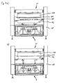
- Fig. 4a shows a similar structure as Fig. 3a ,
- the packages 60 are here flatter and accordingly located the tool upper part 17 in a, with respect to in 3a, b described position, lower position. In this way, unnecessary stroke is avoided, whereby the cycle performance of the packaging machine can be increased. It is also conceivable to make the upper tool part 17 automatically movable.
- Fig. 4b shows the hoist 1 or the lower tool part 16 in a raised position. In this position, the packages 60 (see Fig. 4a ) sealed.
- the invention is not limited to use in a tray sealer. Rather, it is also applicable to a thermoforming machine or a chamber belt machine.
- the hoist should not be limited to the described embodiment. It can be used in any workstation of a packaging machine. It is also conceivable, for example, that a tool upper part is lowered or lifted off and the lower tool part is stationary.
Description
- Die vorliegende Erfindung bezieht sich auf eine Verpackungsmaschine mit einem Hubwerk, insbesondere auf eine Schalenverschließmaschine oder eine Tiefziehmaschine.
- Im Bereich der Verpackungsmaschinen sind Hubwerke bekannt, die zur Realisierung der Hubbewegung Kniehebelsysteme verwenden. Diese Systeme können je nach Hubstellung bzw. Winkeistellung des Hebelsystems durch die Verlagerung des Kraftangriffpunkts unterschiedlich große Kräfte aufnehmen, was gerade bei Siegelstationen mit variabler Siegelhöhe unvorteilhaft ist. Hier ist vielmehr ein in jedem Arbeitspunkt erzeugbarer konstanter Siegeldruck gewünscht.
- Es sind weiterhin beispielsweise aus der
EP 0 352 466 A1 Hubwerke mit Spindelantrieben bekannt. Um die hohen Kräfte, die z.B. bei einer Siegelstation wirken, aufzunehmen, müssen die Durchmesser der Spindeln mit Berücksichtigung des Sicherheitsfaktors gegen Knicken ausreichend groß dimensioniert werden. Dies wirkt sich unvorteilhaft auf die Dynamik des Systems, wie z.B. auf die Verfahrzeiten und somit auf die Taktleistung der Verpackungsmaschine, aus. Darüber hinaus sind bei herkömmlichen Spindelhubwerken unvorteilhafte Bauhöhen erforderlich, da die Spindeln die erforderliche Vertikalbewegung ausführen. - Eine Verpackungsmaschine gemäß dem Oberbegriff des Anspruchs 1 geht aus der
JP 08-217007 A - Die Aufgabe der vorliegenden Erfindung ist es, eine Verpackungsmaschine mit einem Hubwerk bereitzustellen, das im Wesentlichen in jeder Hubstellung die gleichen Kräfte aufnehmen kann, eine kürzere Verfahrzeit aufweist und einen sichereren Betrieb gewährleistet.
- Die Aufgabe wird gelöst durch eine Verpackungsmaschine gemäß Anspruch 1. Weiterbildungen der Erfindung sind in den Unteransprüchen angegeben.
- Durch den erfindungsgemäßen Spindelantrieb können an den einzelnen Arbeitsstationen einer Verpackungsmaschine auch große Kräfte in jeder Hubstellung aufgenommen werden. Auf diese Weise ist beispielsweise eine Schließbewegung eines Werkzeugunterteils gegen ein ortsfestes Werkzeugoberteil optimal mess- und regelbar.
- Da in der erfindungsgemäßen Konstruktion eine Spindelmutter die Vertikalbewegung ausführt und die Spindel ortsfest bleibt, wird diese lediglich auf Zug beansprucht, d. h. die Knickgefahr ist ausgeschlossen. Auf diese Weise kann der Durchmesser der Spindel relativ klein dimensioniert werden, was sich positiv auf die Dynamik des Systems, wie z.B. auf die Verfahrzeiten des Hubwerks und somit auf die Taktleistung der Verpackungsmaschine auswirkt. Da die Spindel ortsfest bleibt, kann die Bauhöhe des Hubwerks gering gehalten werden.
- Durch Führungsstangen, die eine reine Vertikalbewegung ausführen, kann das Gesamtsystem des Hubwerks mit einfachen und somit kostengünstigen Mitteln gedichtet werden. Da die Spindel im Betrieb der Hubvorrichtung ortsfest bleibt, müssen in einem Hubwerksgehäusedeckel lediglich Runddichtungen in Form von Abstreifern für die Führungsstangen vorgesehen werden. Das Hubwerk bildet auf diese Weise eine in sich geschlossene und somit hygienegerechte Einheit.
- Weitere Merkmale und Zweckmäßigkeiten der Erfindung ergeben sich aus der Beschreibung von Ausführungsbeispielen anhand der beigefügten Zeichnungen. Von den Figuren zeigen:
- Fig. 1
- eine schematische Seitenansicht einer Verpackungs- maschine;
- Fig. 2
- eine schematische perspektivische Ansicht des Hub- werks;
- Fig. 3a
- eine schematische Seitenansicht des Hubwerks in ab- gesenkter Stellung mit einem Werkzeugoberteil in einer ersten Stellung;
- Fig. 3b
- eine schematische Seitenansicht des Hubwerks in an- gehobener Stellung mit einem Werkzeugoberteil in einer ersten Stellung;
- Fig. 4a
- eine schematische Seitenansicht des Hubwerks in ab- gesenkter Stellung mit einem Werkzeugoberteil in einer zweiten Stellung;
- Fig. 4b
- eine schematische Seitenansicht des Hubwerks in an- gehobener Stellung mit einem Werkzeugoberteil in einer zweiten Stellung.
- Im Folgenden wird mit Bezug auf
Fig. 1 bis Fig. 3b eine erste Ausführungsform der Erfindung beispielhaft an einer Schalenverschließmaschine bzw. einem Traysealer beschrieben. -
Fig. 1 zeigt einen Traysealer mit einem ersten Förderband 20, einem zweiten Förderband 30, einem dritten Förderband 70, einem Greifer 40, einer Evakuier- und Siegelstation 50 und einem Hubwerk 1. - Im Betrieb werden Verpackungen 60 durch das erste Förderband 20 auf das zweite Förderband 30 übergeben. Die Verpackungen 60 werden durch den Greifer 40 in die Evakuier- und Siegelstation 50 befördert. Die Siegelung findet durch die Anhebung der Verpackungen 60 durch das Hubwerk 1 statt. Die evakuierten und gesiegelten Verpackungen 60 werden schließlich durch das dritte Förderband 70 abtransportiert.
-
Fig. 2 zeigt das Hubwerk 1 in einer schematischen perspektivischen Ansicht. Zusammen mit einem Gestell 2 bildet eine Trägerplatte 3 aus der Seitenansicht betrachtet eine trapez-förmige Basisbaugruppe des Hubwerks 1. Auf der Oberseite der Trägerplatte 3 sind durch eine weitere kleinere Platte erhöht eine Antriebsrolle 4 und zwei Umlenkrollen 4a vorgesehen, wobei die Antriebsrolle 4 im Wesentlichen zwischen den beiden Umlenkrollen 4a angeordnet ist. Die Antriebsrolle 4 ist über eine (nicht gezeigte) Antriebswelle mit einem Motor 15, z.B. in Form eines Elektro-Servomotors, verbunden. Der Motor 15 ist unter der Trägerplatte 3 angeordnet. - Das Hubwerk 1 ist bezüglich einer Ebene, die durch die Rotationsachse der Antriebsrolle 4 und die Mittelpunkte der Längskanten der Oberseite der Trägerplatte 3 verläuft, im Wesentlichen symmetrisch. Die Trägerplatte 3 weist an ihren beiden schmaleren Seiten jeweils drei Bohrungen auf. In der jeweils mittleren Bohrung ist eine Spindel 6 durch eine Spindellagerung 13 gelagert. Die beiden Spindeln 6 erstrecken sich durch die mittleren Bohrungen in der Trägerplatte 3 nach unten. Die Spindeln 6 wirken mit zwei Spindelmuttern 8 zusammen, die in mittleren Bohrungen von zwei Hubplatten 7 vorgesehen sind. Die Hubplatten 7 sind ihrerseits jeweils fest mit zwei Führungsstangen 9 versehen, die sich nach oben erstrecken-und durch die jeweils beiden vorgenannten äußeren Bohrungen, die an den schmaleren Seiten der Trägerplatte 3 vorgesehen sind, treten. Zur translatorischen Führung der Führungsstangen 9 sind in die Trägerplatte 3 Linearführungen 10 eingelassen bzw. erstrecken sich weiter nach oben und treten durch eine bzw. insgesamt zwei Gegenplatte(n) 11. Auf diesen Gegenplatten 11 ist pro Führungsstange 9 eine Bremse 12 vorgesehen, die die Führungsstangen 9 umschließen und die im Betrieb bei angehobenem Hubwerk 1 eine unbeabsichtigte Absenkung desselben verhindern sollen. Die Bremsen 12 werden z.B. elektromagnetisch gelüftet und werden über eine Federkraft betätigt. Die Bremsen 12 sind aus Sicherheitsgründen vom Rest des Systems unabhängig betreibbar. Außerdem ist auf jeder Gegenplatte 11 jeweils ein Gegenlager 14 zur Lagerung der Spindeln 6 vorgesehen.
- Die Spindeln 6 werden im Betrieb über einen Riemen 5, beispielsweise in Form eines Zahnriemens, der durch die Antriebsrolle 4 angetrieben wird, angetrieben. Der Riemen 5 kann durch die exzentrisch gelagerten Umlenkrollen 4a gespannt bzw. bei Bedarf nachgespannt werden. Durch den Riemen 5 ist darüber hinaus sichergestellt, dass die beiden Spindeln 6 synchron betrieben werden und es nicht zu einer Verkippung des Hubwerks 1 kommt.
- Im Betrieb des Hubwerks 1 treibt der Motor 15 die Antriebsrolle 4 und diese wiederum den Riemen 5 an. Die beiden Spindeln 6 werden auf diese Weise je nach Bewegungsrichtung synchron in die entsprechende Richtung rotiert. Die Spindeln 6 wirken mit den Spindelmuttern 8 zusammen und die Hubplatten 7 werden zusammen mit den Führungsstangen 9 angehoben bzw. abgesenkt. Die Führungsstangen 9 sind an ihrem oberen Ende mit einem Werkzeugunterteil 16 (siehe
Fig. 3a bis 4b ) verbunden und heben dieses an bzw. senken es ab. Die Führungsstangen 9 sind als Rohre ausgeführt und nehmen in ihrem Inneren Versorgungs-, Entsorgungs- oder Steuerleitungen, z.B. Gasleitungen für die Begasung oder die Evakuierung einer Kammer einer Verpackungsmaschine, die durch ein Werkzeugunterteil 16 und ein Werkzeugoberteil 17 (sieheFig. 3a bis 4b ) gebildet wird, auf. Die hohlen Führungsstangen 9 können aber auch selbst als Leitungen dienen. Sobald das Hubwerk seine gewünschte angehobene Endposition erreicht hat, blockieren die Bremsen 12. Aus Sicherheitsgründen wird erst dann mit dem Prozess fortgefahren, z.B. gesiegelt. -
Fig.3a zeigt das in einen Rahmen 18 einer Evakuier- und Versiegelungsstation 50 integrierte Hubwerk 1 in einer schematischen Seitenansicht. Das Hubwerk 1 bzw. das Werkzeugunterteil 16 mit den darauf befindlichen bereits befüllten Verpackungen 60, befindet sich in einer abgesenkten Position. Das Werkzeugoberteil 17 ist ortsfest. Das Hubwerk 1 ist im Betrieb in einem geschlossenen Gehäuse angeordnet. Die Bohrungen für die Führungsstangen 9 schließen mit diesen dicht ab. Auf diese Weise wird eine hygienegerechte Konstruktion geschaffen. -
Fig. 3b zeigt das Hubwerk 1 bzw. das Werkzeugunterteil 16 in einer angehobenen Position. In dieser Stellung werden die Verpackungen 60 (sieheFig. 3a ) gesiegelt. -
Fig. 4a zeigt einen ähnlichen Aufbau wieFig. 3a . Die Verpackungen 60 sind hier flacher und dementsprechend befindet sich das Werkzeugoberteil 17 in einer, bezüglich der inFig.3a,b beschriebenen Stellung, tieferen Stellung. Auf diese Weise wird unnötiger Hubweg vermieden, wodurch die Taktleistung der Verpackungsmaschine erhöht werden kann. Es ist auch denkbar das Werkzeugoberteil 17 automatisch verfahrbar zu gestalten. -
Fig. 4b zeigt das Hubwerk 1 bzw. das Werkzeugunterteil 16 in einer angehobenen Position. In dieser Stellung werden die Verpackungen 60 (sieheFig. 4a ) gesiegelt. - Die Erfindung ist nicht auf die Anwendung in einem Traysealer beschränkt. Vielmehr ist sie auch auf eine Tiefziehmaschine oder eine Kammerbandmaschine anwendbar.
- Das Hubwerk soll nicht auf die beschriebene Ausführungsform beschränkt sein. Es ist in jeder beliebige Arbeitsstation einer Verpackungsmaschine einsetzbar. Es ist beispielsweise auch denkbar, dass ein Werkzeugoberteil abgesenkt bzw. abgehoben wird und das Werkzeugunterteil ortsfest ist.
- Es ist auch denkbar nur eine Spindel zur Realisierung der Hubbewegung des Hubwerks vorzusehen.
Claims (13)
- Verpackungsmaschine mit einem Hubwerk (1), das zumindest eine Spindel (6) und eine Spindelmutter (8) aufweist, wobei die Spindel (6) motorisch antreibbar und relativ zu einem Gestell (2) ortsfest ist,
und wobei eine Mehrzahl von Führungsstangen (9) vorgesehen ist, die durch die Hubplatte (7) anhebbar und absenkbar sind,
dadurch gekennzeichnet, dass eine Bremse (12) an einer Führungsstange (9) vorgesehen ist. - Verpackungsmaschine gemäß 1, dadurch gekennzeichnet, dass die Spindelmutter (8) in einer Hubplatte (7) vorgesehen ist.
- Verpackungsmaschine gemäß 1 oder 2, dadurch gekennzeichnet, dass die Spindelmutter (8) als Hubplatte (7) ausgebildet ist.
- Verpackungsmaschine gemäß einem der Ansprüche 1 bis 3, dadurch gekennzeichnet, dass die Führungsstangen (9) mit einem Werkzeugunterteil (16) verbindbar sind.
- Verpackungsmaschine gemäß einem der Ansprüche 1 bis 4, dadurch gekennzeichnet, dass wenigstens zwei Spindeln (6) vorgesehen sind.
- Verpackungsmaschine gemäß Anspruch 5, dadurch gekennzeichnet, dass die Spindeln (6) synchronisiert antreibbar sind.
- Verpackungsmaschine gemäß Anspruch 5 oder 6, dadurch gekennzeichnet, dass die Spindeln (6) über ein Zugmittel (5) synchronisiert antreibbar sind.
- Verpackungsmaschine gemäß Anspruch 5 oder 6, dadurch gekennzeichnet, dass die Spindeln (6) jeweils unabhängig voneinander antreibbar sind.
- Verpackungsmaschine gemäß einem der vorangehenden Ansprüche, dadurch gekennzeichnet, dass die Führungsstangen (9) hohl ausgebildet sind.
- Verpackungsmaschine gemäß einem der vorangehenden Ansprüche, dadurch gekennzeichnet, dass in den Führungsstangen (9) Versorgungs-, Entsorgungs- oder Steuerleitungen vorgesehen sind.
- Verpackungsmaschine gemäß einem der vorangehenden Ansprüche, dadurch gekennzeichnet, dass die Führungsstangen (9) selbst als Versorgungs-, Entsorgungs-oder Steuerleitungen ausgebildet sind.
- Verpackungsmaschine gemäß einem der vorangehenden Ansprüche, dadurch gekennzeichnet, dass an jeder Führungsstange (9) eine Bremse (12) vorgesehen ist.
- Verpackungsmaschine gemäß einem der vorangehenden Ansprüche, dadurch gekennzeichnet, dass die Bremsen (12) elektromagnetisch gelüftet und über eine Federkraft betätigt werden.
Applications Claiming Priority (1)
| Application Number | Priority Date | Filing Date | Title |
|---|---|---|---|
| DE102008023319.6A DE102008023319B4 (de) | 2008-05-13 | 2008-05-13 | Verpackungsmaschine mit einem spindeltrieb-hubwerk |
Publications (2)
| Publication Number | Publication Date |
|---|---|
| EP2119633A1 EP2119633A1 (de) | 2009-11-18 |
| EP2119633B1 true EP2119633B1 (de) | 2011-01-26 |
Family
ID=40810194
Family Applications (1)
| Application Number | Title | Priority Date | Filing Date |
|---|---|---|---|
| EP09160139A Not-in-force EP2119633B1 (de) | 2008-05-13 | 2009-05-13 | Verpackungsmaschine mit einem Hubwerk |
Country Status (6)
| Country | Link |
|---|---|
| US (1) | US8001749B2 (de) |
| EP (1) | EP2119633B1 (de) |
| CN (1) | CN101580141B (de) |
| AT (1) | ATE496831T1 (de) |
| DE (2) | DE102008023319B4 (de) |
| ES (1) | ES2356302T3 (de) |
Families Citing this family (18)
| Publication number | Priority date | Publication date | Assignee | Title |
|---|---|---|---|---|
| AU2004100000A4 (en) | 2004-01-02 | 2004-02-12 | Sands Innovations Pty Ltd | Dispensing stirring implement |
| BRPI0806943A2 (pt) | 2007-01-31 | 2014-05-06 | Sands Innovations Pty Ltd | Utensílio de dispensação e método de fabricação para o mesmo |
| EP2373551B1 (de) | 2008-12-09 | 2015-04-08 | Sands Innovations Pty Ltd. | Abgabebehälter |
| USD636890S1 (en) | 2009-09-17 | 2011-04-26 | Sands Innovations Pty. Ltd. | Dispensing utensil |
| US9828125B2 (en) | 2009-10-20 | 2017-11-28 | Cvp Systems, Inc. | Modified atmosphere packaging apparatus and method with automated bag production |
| US8511500B2 (en) | 2010-06-07 | 2013-08-20 | Sands Innovations Pty. Ltd. | Dispensing container |
| GB201016930D0 (en) * | 2010-10-07 | 2010-11-24 | Ishida Europ Ltd | Lifting apparatus |
| WO2012065640A1 (de) * | 2010-11-17 | 2012-05-24 | Inauen Group Ag | Vakuumverpackungsmaschine |
| US8485360B2 (en) | 2011-03-04 | 2013-07-16 | Sands Innovations Pty, Ltd. | Fracturable container |
| EP2517963B1 (de) * | 2011-04-29 | 2013-10-23 | Multivac Sepp Haggenmüller GmbH & Co. KG | Verpackungsmaschine mit Transporteinrichtung |
| DE102011105513A1 (de) | 2011-06-24 | 2012-12-27 | Multivac Sepp Haggenmüller Gmbh & Co. Kg | Verfahren und Siegelstation zum Versiegeln von Verpackungen |
| DE102011106826A1 (de) * | 2011-07-07 | 2013-01-10 | Multivac Sepp Haggenmüller Gmbh & Co. Kg | Schalenverschließmaschine |
| DE102012006699A1 (de) * | 2012-03-30 | 2013-10-02 | Multivac Sepp Haggenmüller Gmbh & Co. Kg | Mehrreihige Siegelstation |
| ES2544533T3 (es) | 2012-12-19 | 2015-09-01 | Multivac Sepp Haggenmüller Gmbh & Co. Kg | Máquina de embalaje de embutición profunda con mecanismo elevador electromotor |
| EP2749499B1 (de) * | 2012-12-28 | 2015-06-10 | Multivac Sepp Haggenmüller GmbH & Co. KG | Verpackungsmaschine mit einer Schutzeinrichtung und Verfahren |
| US10407199B2 (en) | 2015-08-28 | 2019-09-10 | Cvp Systems Llc | Packaging apparatus with package dividing seal mechanism |
| DE102018222836A1 (de) * | 2018-12-21 | 2020-06-25 | Multivac Sepp Haggenmüller Se & Co. Kg | Siegeln von kartonzuschnitten mittels auflage auf transportband |
| CN112109984B (zh) * | 2020-09-24 | 2022-03-15 | 江苏省勤奋药业有限公司 | 一种氯化镁包装用密封机及其工作方法 |
Family Cites Families (19)
| Publication number | Priority date | Publication date | Assignee | Title |
|---|---|---|---|---|
| US20973A (en) * | 1858-07-20 | Improvement in cotton-presses | ||
| US1354371A (en) * | 1916-11-25 | 1920-09-28 | Edward H Angier | Method of wrapping tires and the like and machine for practising the same |
| US3590437A (en) * | 1968-08-08 | 1971-07-06 | Usm Corp | Injection molding presses |
| DE2008395A1 (de) * | 1970-02-24 | 1971-09-16 | Demag AG 4100 Duisburg | Vorrichtung zum Pressen und Abpacken von schuttfahigem Gut, insbesondere Mull |
| US3943844A (en) * | 1974-12-12 | 1976-03-16 | Ann Arbor Baler Company | Baling machine |
| DE2506179A1 (de) * | 1975-02-14 | 1976-08-26 | Hassia Verpackung Gmbh | Tiefzieh- und fuellmaschine |
| US4036152A (en) * | 1975-11-17 | 1977-07-19 | General Motors Corporation | Refuse compactor-incinerator disposer |
| DE3228935C2 (de) * | 1982-08-03 | 1984-10-31 | Rationator-Maschinenbau Gmbh, 6521 Hillesheim | Vorrichtung zum Bewegen von Dosierkolben und von Füllrohren |
| DE3513388A1 (de) * | 1985-04-15 | 1986-10-16 | Bernd Dipl.-Ing. 7517 Waldbronn Schenk | Vorrichtung zur herstellung von kunststoff-formteilen insbesondere von kunststoff-hohlkoerpern |
| DE3825061A1 (de) * | 1988-07-23 | 1990-01-25 | Geiss Georg Maschf | Vakuumformmaschine |
| US5282732A (en) * | 1992-04-08 | 1994-02-01 | Davidson Textron Inc. | Mold press assembly |
| IT232075Y1 (it) * | 1994-10-11 | 1999-08-16 | Corob Srl | Miscelatore di prodotti generalmente collocati in contenitori e gruppo di sostegno e serraggio per almeno uno di tali contenitori, |
| JP3755915B2 (ja) * | 1995-02-17 | 2006-03-15 | 大森機械工業株式会社 | 包装装置における下側ボックスの昇降装置及びその制御方法ならびに包装装置 |
| NL1003997C2 (nl) | 1996-09-10 | 1998-03-16 | Ps Systems B V | Pers voor het bewerken van voorwerpen van micro-elektronica. |
| DE19815434A1 (de) * | 1998-04-07 | 1999-10-14 | Focke & Co | Hubvorrichtung (Palettierer) mit Schwenkarm |
| US6804929B2 (en) * | 2001-06-13 | 2004-10-19 | Tadeusz Kemnitz | Rotary capping apparatus and feedback control system for regulating applied torque |
| DE10327092A1 (de) * | 2003-06-13 | 2004-12-30 | Cfs Germany Gmbh | Arbeitsstation und Verpackungsmaschine |
| DE102004063931B8 (de) * | 2004-01-08 | 2010-02-11 | Joachim Braun | Verpackungsvorrichtung zum Verpacken von Paletten |
| JP4868956B2 (ja) * | 2006-06-23 | 2012-02-01 | シーケーディ株式会社 | ブリスター包装機 |
-
2008
- 2008-05-13 DE DE102008023319.6A patent/DE102008023319B4/de not_active Expired - Fee Related
-
2009
- 2009-05-11 US US12/454,029 patent/US8001749B2/en not_active Expired - Fee Related
- 2009-05-13 CN CN2009101393717A patent/CN101580141B/zh not_active Expired - Fee Related
- 2009-05-13 EP EP09160139A patent/EP2119633B1/de not_active Not-in-force
- 2009-05-13 ES ES09160139T patent/ES2356302T3/es active Active
- 2009-05-13 DE DE502009000341T patent/DE502009000341D1/de active Active
- 2009-05-13 AT AT09160139T patent/ATE496831T1/de active
Also Published As
| Publication number | Publication date |
|---|---|
| DE102008023319B4 (de) | 2014-05-28 |
| CN101580141A (zh) | 2009-11-18 |
| DE102008023319A1 (de) | 2009-11-19 |
| US8001749B2 (en) | 2011-08-23 |
| CN101580141B (zh) | 2013-02-20 |
| DE502009000341D1 (de) | 2011-03-10 |
| EP2119633A1 (de) | 2009-11-18 |
| ES2356302T3 (es) | 2011-04-06 |
| US20090288365A1 (en) | 2009-11-26 |
| ATE496831T1 (de) | 2011-02-15 |
Similar Documents
| Publication | Publication Date | Title |
|---|---|---|
| EP2119633B1 (de) | Verpackungsmaschine mit einem Hubwerk | |
| DE102009017871B4 (de) | Auswerfereinrichtung für eine Umformeinrichtung | |
| EP2915773B1 (de) | Vorrichtung und Verfahren zum Befüllen eines Behälters mit einem Füllprodukt | |
| EP2768661B1 (de) | Presse | |
| DE102012009108A1 (de) | Transfervorrichtung für Werkstücke | |
| DE4028484C2 (de) | ||
| EP2500085A1 (de) | Höhenverstellvorrichtung für ein getauchtes Rühr- oder Pumpwerk | |
| DE102011116654A1 (de) | Vorrichtung zum Stanznieten und Durchsetzfügen unter beengten Platzverhältnissen | |
| DE4325180C2 (de) | Schließeinheit für eine Spritzmaschine und Verfahren zum Betrieb derselben | |
| DE10218633B3 (de) | Presse | |
| EP3998218A1 (de) | Arbeitsstation mit hubmechanismus für eine verpackungsmaschine | |
| EP2942187A1 (de) | Rundläuferpresse | |
| DE2806987C3 (de) | Vorrichtung zum Manipulieren von Werkstücken | |
| DE202015009453U1 (de) | Zugkurbelhubwerk für Verpackungsmaschine | |
| EP3838769B1 (de) | Arbeitsstation für eine verpackungsmaschine mit einem hubwerk mit kniehebelmechanismus | |
| DE2856000C2 (de) | Vorrichtung zum Abschrecken von Blechen | |
| DE2557647C2 (de) | Probeentnahmevorrichtung für eine Schüttgutladung | |
| EP3130546A1 (de) | Zugkurbelhubwerk für verpackungsmaschine | |
| DE102013109971A1 (de) | Vorrichtung zum Dosieren eines Füllproduktes in einen zu befüllenden Behälter | |
| EP0309929A1 (de) | Behälterhubanordnung für Getränkefülleinrichtungen | |
| CH716835A2 (de) | Hubeinheit für ein Mittelstreifenüberleitungssystem. | |
| DE102007012400B4 (de) | Vorrichtung zum Anheben und Positionieren von Lasten in verschiedenen Höhenbereichen, zum Beispiel von Karosserien im Kfz-Bau | |
| CN113334818B (zh) | 一种四柱液压机的液压系统 | |
| DE19721072A1 (de) | Tragbare Elektropreßvorrichtung | |
| EP3816055B1 (de) | Hubwerkswechsel |
Legal Events
| Date | Code | Title | Description |
|---|---|---|---|
| PUAI | Public reference made under article 153(3) epc to a published international application that has entered the european phase |
Free format text: ORIGINAL CODE: 0009012 |
|
| 17P | Request for examination filed |
Effective date: 20090828 |
|
| AK | Designated contracting states |
Kind code of ref document: A1 Designated state(s): AT BE BG CH CY CZ DE DK EE ES FI FR GB GR HR HU IE IS IT LI LT LU LV MC MK MT NL NO PL PT RO SE SI SK TR |
|
| 17Q | First examination report despatched |
Effective date: 20100331 |
|
| GRAP | Despatch of communication of intention to grant a patent |
Free format text: ORIGINAL CODE: EPIDOSNIGR1 |
|
| RIN1 | Information on inventor provided before grant (corrected) |
Inventor name: NEGELE, WOLFGANG |
|
| GRAS | Grant fee paid |
Free format text: ORIGINAL CODE: EPIDOSNIGR3 |
|
| GRAA | (expected) grant |
Free format text: ORIGINAL CODE: 0009210 |
|
| AK | Designated contracting states |
Kind code of ref document: B1 Designated state(s): AT BE BG CH CY CZ DE DK EE ES FI FR GB GR HR HU IE IS IT LI LT LU LV MC MK MT NL NO PL PT RO SE SI SK TR |
|
| REG | Reference to a national code |
Ref country code: GB Ref legal event code: FG4D Free format text: NOT ENGLISH |
|
| REG | Reference to a national code |
Ref country code: CH Ref legal event code: EP |
|
| REG | Reference to a national code |
Ref country code: IE Ref legal event code: FG4D Free format text: LANGUAGE OF EP DOCUMENT: GERMAN |
|
| REF | Corresponds to: |
Ref document number: 502009000341 Country of ref document: DE Date of ref document: 20110310 Kind code of ref document: P |
|
| REG | Reference to a national code |
Ref country code: DE Ref legal event code: R096 Ref document number: 502009000341 Country of ref document: DE Effective date: 20110310 |
|
| REG | Reference to a national code |
Ref country code: ES Ref legal event code: FG2A Ref document number: 2356302 Country of ref document: ES Kind code of ref document: T3 Effective date: 20110406 |
|
| REG | Reference to a national code |
Ref country code: NL Ref legal event code: T3 |
|
| LTIE | Lt: invalidation of european patent or patent extension |
Effective date: 20110126 |
|
| PG25 | Lapsed in a contracting state [announced via postgrant information from national office to epo] |
Ref country code: SE Free format text: LAPSE BECAUSE OF FAILURE TO SUBMIT A TRANSLATION OF THE DESCRIPTION OR TO PAY THE FEE WITHIN THE PRESCRIBED TIME-LIMIT Effective date: 20110126 Ref country code: LV Free format text: LAPSE BECAUSE OF FAILURE TO SUBMIT A TRANSLATION OF THE DESCRIPTION OR TO PAY THE FEE WITHIN THE PRESCRIBED TIME-LIMIT Effective date: 20110126 Ref country code: NO Free format text: LAPSE BECAUSE OF FAILURE TO SUBMIT A TRANSLATION OF THE DESCRIPTION OR TO PAY THE FEE WITHIN THE PRESCRIBED TIME-LIMIT Effective date: 20110426 Ref country code: HR Free format text: LAPSE BECAUSE OF FAILURE TO SUBMIT A TRANSLATION OF THE DESCRIPTION OR TO PAY THE FEE WITHIN THE PRESCRIBED TIME-LIMIT Effective date: 20110126 Ref country code: GR Free format text: LAPSE BECAUSE OF FAILURE TO SUBMIT A TRANSLATION OF THE DESCRIPTION OR TO PAY THE FEE WITHIN THE PRESCRIBED TIME-LIMIT Effective date: 20110427 Ref country code: LT Free format text: LAPSE BECAUSE OF FAILURE TO SUBMIT A TRANSLATION OF THE DESCRIPTION OR TO PAY THE FEE WITHIN THE PRESCRIBED TIME-LIMIT Effective date: 20110126 Ref country code: PT Free format text: LAPSE BECAUSE OF FAILURE TO SUBMIT A TRANSLATION OF THE DESCRIPTION OR TO PAY THE FEE WITHIN THE PRESCRIBED TIME-LIMIT Effective date: 20110526 |
|
| REG | Reference to a national code |
Ref country code: IE Ref legal event code: FD4D |
|
| PG25 | Lapsed in a contracting state [announced via postgrant information from national office to epo] |
Ref country code: SI Free format text: LAPSE BECAUSE OF FAILURE TO SUBMIT A TRANSLATION OF THE DESCRIPTION OR TO PAY THE FEE WITHIN THE PRESCRIBED TIME-LIMIT Effective date: 20110126 Ref country code: BG Free format text: LAPSE BECAUSE OF FAILURE TO SUBMIT A TRANSLATION OF THE DESCRIPTION OR TO PAY THE FEE WITHIN THE PRESCRIBED TIME-LIMIT Effective date: 20110426 Ref country code: CY Free format text: LAPSE BECAUSE OF FAILURE TO SUBMIT A TRANSLATION OF THE DESCRIPTION OR TO PAY THE FEE WITHIN THE PRESCRIBED TIME-LIMIT Effective date: 20110126 Ref country code: FI Free format text: LAPSE BECAUSE OF FAILURE TO SUBMIT A TRANSLATION OF THE DESCRIPTION OR TO PAY THE FEE WITHIN THE PRESCRIBED TIME-LIMIT Effective date: 20110126 Ref country code: PL Free format text: LAPSE BECAUSE OF FAILURE TO SUBMIT A TRANSLATION OF THE DESCRIPTION OR TO PAY THE FEE WITHIN THE PRESCRIBED TIME-LIMIT Effective date: 20110126 |
|
| PG25 | Lapsed in a contracting state [announced via postgrant information from national office to epo] |
Ref country code: DK Free format text: LAPSE BECAUSE OF FAILURE TO SUBMIT A TRANSLATION OF THE DESCRIPTION OR TO PAY THE FEE WITHIN THE PRESCRIBED TIME-LIMIT Effective date: 20110126 Ref country code: IE Free format text: LAPSE BECAUSE OF FAILURE TO SUBMIT A TRANSLATION OF THE DESCRIPTION OR TO PAY THE FEE WITHIN THE PRESCRIBED TIME-LIMIT Effective date: 20110126 Ref country code: EE Free format text: LAPSE BECAUSE OF FAILURE TO SUBMIT A TRANSLATION OF THE DESCRIPTION OR TO PAY THE FEE WITHIN THE PRESCRIBED TIME-LIMIT Effective date: 20110126 |
|
| BERE | Be: lapsed |
Owner name: MULTIVAC SEPP HAGGENMULLER G.M.B.H. & CO. KG Effective date: 20110531 |
|
| PG25 | Lapsed in a contracting state [announced via postgrant information from national office to epo] |
Ref country code: CZ Free format text: LAPSE BECAUSE OF FAILURE TO SUBMIT A TRANSLATION OF THE DESCRIPTION OR TO PAY THE FEE WITHIN THE PRESCRIBED TIME-LIMIT Effective date: 20110126 Ref country code: RO Free format text: LAPSE BECAUSE OF FAILURE TO SUBMIT A TRANSLATION OF THE DESCRIPTION OR TO PAY THE FEE WITHIN THE PRESCRIBED TIME-LIMIT Effective date: 20110126 Ref country code: SK Free format text: LAPSE BECAUSE OF FAILURE TO SUBMIT A TRANSLATION OF THE DESCRIPTION OR TO PAY THE FEE WITHIN THE PRESCRIBED TIME-LIMIT Effective date: 20110126 |
|
| PLBE | No opposition filed within time limit |
Free format text: ORIGINAL CODE: 0009261 |
|
| STAA | Information on the status of an ep patent application or granted ep patent |
Free format text: STATUS: NO OPPOSITION FILED WITHIN TIME LIMIT |
|
| PG25 | Lapsed in a contracting state [announced via postgrant information from national office to epo] |
Ref country code: MC Free format text: LAPSE BECAUSE OF NON-PAYMENT OF DUE FEES Effective date: 20110531 Ref country code: MT Free format text: LAPSE BECAUSE OF FAILURE TO SUBMIT A TRANSLATION OF THE DESCRIPTION OR TO PAY THE FEE WITHIN THE PRESCRIBED TIME-LIMIT Effective date: 20110126 |
|
| 26N | No opposition filed |
Effective date: 20111027 |
|
| REG | Reference to a national code |
Ref country code: DE Ref legal event code: R097 Ref document number: 502009000341 Country of ref document: DE Effective date: 20111027 |
|
| PG25 | Lapsed in a contracting state [announced via postgrant information from national office to epo] |
Ref country code: BE Free format text: LAPSE BECAUSE OF NON-PAYMENT OF DUE FEES Effective date: 20110531 |
|
| PGFP | Annual fee paid to national office [announced via postgrant information from national office to epo] |
Ref country code: NL Payment date: 20120531 Year of fee payment: 4 Ref country code: DE Payment date: 20120529 Year of fee payment: 4 |
|
| PGFP | Annual fee paid to national office [announced via postgrant information from national office to epo] |
Ref country code: FR Payment date: 20120614 Year of fee payment: 4 |
|
| PGFP | Annual fee paid to national office [announced via postgrant information from national office to epo] |
Ref country code: IT Payment date: 20120531 Year of fee payment: 4 |
|
| PGFP | Annual fee paid to national office [announced via postgrant information from national office to epo] |
Ref country code: ES Payment date: 20120522 Year of fee payment: 4 |
|
| PG25 | Lapsed in a contracting state [announced via postgrant information from national office to epo] |
Ref country code: MK Free format text: LAPSE BECAUSE OF FAILURE TO SUBMIT A TRANSLATION OF THE DESCRIPTION OR TO PAY THE FEE WITHIN THE PRESCRIBED TIME-LIMIT Effective date: 20110126 |
|
| PG25 | Lapsed in a contracting state [announced via postgrant information from national office to epo] |
Ref country code: LU Free format text: LAPSE BECAUSE OF NON-PAYMENT OF DUE FEES Effective date: 20110513 |
|
| PG25 | Lapsed in a contracting state [announced via postgrant information from national office to epo] |
Ref country code: IS Free format text: LAPSE BECAUSE OF FAILURE TO SUBMIT A TRANSLATION OF THE DESCRIPTION OR TO PAY THE FEE WITHIN THE PRESCRIBED TIME-LIMIT Effective date: 20110126 |
|
| PG25 | Lapsed in a contracting state [announced via postgrant information from national office to epo] |
Ref country code: HU Free format text: LAPSE BECAUSE OF FAILURE TO SUBMIT A TRANSLATION OF THE DESCRIPTION OR TO PAY THE FEE WITHIN THE PRESCRIBED TIME-LIMIT Effective date: 20110126 |
|
| REG | Reference to a national code |
Ref country code: NL Ref legal event code: V1 Effective date: 20131201 |
|
| REG | Reference to a national code |
Ref country code: CH Ref legal event code: PL |
|
| GBPC | Gb: european patent ceased through non-payment of renewal fee |
Effective date: 20130513 |
|
| PG25 | Lapsed in a contracting state [announced via postgrant information from national office to epo] |
Ref country code: CH Free format text: LAPSE BECAUSE OF NON-PAYMENT OF DUE FEES Effective date: 20130531 Ref country code: DE Free format text: LAPSE BECAUSE OF NON-PAYMENT OF DUE FEES Effective date: 20131203 Ref country code: LI Free format text: LAPSE BECAUSE OF NON-PAYMENT OF DUE FEES Effective date: 20130531 |
|
| REG | Reference to a national code |
Ref country code: DE Ref legal event code: R119 Ref document number: 502009000341 Country of ref document: DE Effective date: 20131203 |
|
| PG25 | Lapsed in a contracting state [announced via postgrant information from national office to epo] |
Ref country code: IT Free format text: LAPSE BECAUSE OF NON-PAYMENT OF DUE FEES Effective date: 20130513 Ref country code: NL Free format text: LAPSE BECAUSE OF NON-PAYMENT OF DUE FEES Effective date: 20131201 |
|
| REG | Reference to a national code |
Ref country code: FR Ref legal event code: ST Effective date: 20140131 |
|
| PG25 | Lapsed in a contracting state [announced via postgrant information from national office to epo] |
Ref country code: GB Free format text: LAPSE BECAUSE OF NON-PAYMENT OF DUE FEES Effective date: 20130513 |
|
| PG25 | Lapsed in a contracting state [announced via postgrant information from national office to epo] |
Ref country code: FR Free format text: LAPSE BECAUSE OF NON-PAYMENT OF DUE FEES Effective date: 20130531 |
|
| PGFP | Annual fee paid to national office [announced via postgrant information from national office to epo] |
Ref country code: TR Payment date: 20120514 Year of fee payment: 4 |
|
| REG | Reference to a national code |
Ref country code: ES Ref legal event code: FD2A Effective date: 20140606 |
|
| PG25 | Lapsed in a contracting state [announced via postgrant information from national office to epo] |
Ref country code: ES Free format text: LAPSE BECAUSE OF NON-PAYMENT OF DUE FEES Effective date: 20130514 |
|
| REG | Reference to a national code |
Ref country code: AT Ref legal event code: MM01 Ref document number: 496831 Country of ref document: AT Kind code of ref document: T Effective date: 20140513 |
|
| PG25 | Lapsed in a contracting state [announced via postgrant information from national office to epo] |
Ref country code: AT Free format text: LAPSE BECAUSE OF NON-PAYMENT OF DUE FEES Effective date: 20140513 |
|
| PG25 | Lapsed in a contracting state [announced via postgrant information from national office to epo] |
Ref country code: TR Free format text: LAPSE BECAUSE OF NON-PAYMENT OF DUE FEES Effective date: 20130513 |