EP2118977B1 - Boîtier de raccordement et de connexion pour un module solaire - Google Patents
Boîtier de raccordement et de connexion pour un module solaire Download PDFInfo
- Publication number
- EP2118977B1 EP2118977B1 EP08707534A EP08707534A EP2118977B1 EP 2118977 B1 EP2118977 B1 EP 2118977B1 EP 08707534 A EP08707534 A EP 08707534A EP 08707534 A EP08707534 A EP 08707534A EP 2118977 B1 EP2118977 B1 EP 2118977B1
- Authority
- EP
- European Patent Office
- Prior art keywords
- connection
- solar module
- junction box
- housing
- flat conductor
- Prior art date
- Legal status (The legal status is an assumption and is not a legal conclusion. Google has not performed a legal analysis and makes no representation as to the accuracy of the status listed.)
- Not-in-force
Links
Images


Classifications
-
- H—ELECTRICITY
- H01—ELECTRIC ELEMENTS
- H01R—ELECTRICALLY-CONDUCTIVE CONNECTIONS; STRUCTURAL ASSOCIATIONS OF A PLURALITY OF MUTUALLY-INSULATED ELECTRICAL CONNECTING ELEMENTS; COUPLING DEVICES; CURRENT COLLECTORS
- H01R12/00—Structural associations of a plurality of mutually-insulated electrical connecting elements, specially adapted for printed circuits, e.g. printed circuit boards [PCB], flat or ribbon cables, or like generally planar structures, e.g. terminal strips, terminal blocks; Coupling devices specially adapted for printed circuits, flat or ribbon cables, or like generally planar structures; Terminals specially adapted for contact with, or insertion into, printed circuits, flat or ribbon cables, or like generally planar structures
- H01R12/50—Fixed connections
- H01R12/59—Fixed connections for flexible printed circuits, flat or ribbon cables or like structures
- H01R12/592—Fixed connections for flexible printed circuits, flat or ribbon cables or like structures connections to contact elements
-
- H—ELECTRICITY
- H01—ELECTRIC ELEMENTS
- H01R—ELECTRICALLY-CONDUCTIVE CONNECTIONS; STRUCTURAL ASSOCIATIONS OF A PLURALITY OF MUTUALLY-INSULATED ELECTRICAL CONNECTING ELEMENTS; COUPLING DEVICES; CURRENT COLLECTORS
- H01R4/00—Electrically-conductive connections between two or more conductive members in direct contact, i.e. touching one another; Means for effecting or maintaining such contact; Electrically-conductive connections having two or more spaced connecting locations for conductors and using contact members penetrating insulation
- H01R4/28—Clamped connections, spring connections
- H01R4/48—Clamped connections, spring connections utilising a spring, clip, or other resilient member
- H01R4/4809—Clamped connections, spring connections utilising a spring, clip, or other resilient member using a leaf spring to bias the conductor toward the busbar
- H01R4/484—Spring housing details
-
- H—ELECTRICITY
- H01—ELECTRIC ELEMENTS
- H01R—ELECTRICALLY-CONDUCTIVE CONNECTIONS; STRUCTURAL ASSOCIATIONS OF A PLURALITY OF MUTUALLY-INSULATED ELECTRICAL CONNECTING ELEMENTS; COUPLING DEVICES; CURRENT COLLECTORS
- H01R4/00—Electrically-conductive connections between two or more conductive members in direct contact, i.e. touching one another; Means for effecting or maintaining such contact; Electrically-conductive connections having two or more spaced connecting locations for conductors and using contact members penetrating insulation
- H01R4/28—Clamped connections, spring connections
- H01R4/48—Clamped connections, spring connections utilising a spring, clip, or other resilient member
- H01R4/4809—Clamped connections, spring connections utilising a spring, clip, or other resilient member using a leaf spring to bias the conductor toward the busbar
- H01R4/4846—Busbar details
- H01R4/485—Single busbar common to multiple springs
-
- H—ELECTRICITY
- H01—ELECTRIC ELEMENTS
- H01R—ELECTRICALLY-CONDUCTIVE CONNECTIONS; STRUCTURAL ASSOCIATIONS OF A PLURALITY OF MUTUALLY-INSULATED ELECTRICAL CONNECTING ELEMENTS; COUPLING DEVICES; CURRENT COLLECTORS
- H01R4/00—Electrically-conductive connections between two or more conductive members in direct contact, i.e. touching one another; Means for effecting or maintaining such contact; Electrically-conductive connections having two or more spaced connecting locations for conductors and using contact members penetrating insulation
- H01R4/28—Clamped connections, spring connections
- H01R4/48—Clamped connections, spring connections utilising a spring, clip, or other resilient member
- H01R4/489—Clamped connections, spring connections utilising a spring, clip, or other resilient member spring force increased by screw, cam, wedge, or other fastening means
-
- H—ELECTRICITY
- H01—ELECTRIC ELEMENTS
- H01R—ELECTRICALLY-CONDUCTIVE CONNECTIONS; STRUCTURAL ASSOCIATIONS OF A PLURALITY OF MUTUALLY-INSULATED ELECTRICAL CONNECTING ELEMENTS; COUPLING DEVICES; CURRENT COLLECTORS
- H01R9/00—Structural associations of a plurality of mutually-insulated electrical connecting elements, e.g. terminal strips or terminal blocks; Terminals or binding posts mounted upon a base or in a case; Bases therefor
- H01R9/22—Bases, e.g. strip, block, panel
- H01R9/24—Terminal blocks
- H01R9/2416—Means for guiding or retaining wires or cables connected to terminal blocks
-
- H—ELECTRICITY
- H02—GENERATION; CONVERSION OR DISTRIBUTION OF ELECTRIC POWER
- H02G—INSTALLATION OF ELECTRIC CABLES OR LINES, OR OF COMBINED OPTICAL AND ELECTRIC CABLES OR LINES
- H02G3/00—Installations of electric cables or lines or protective tubing therefor in or on buildings, equivalent structures or vehicles
- H02G3/02—Details
- H02G3/08—Distribution boxes; Connection or junction boxes
- H02G3/081—Bases, casings or covers
- H02G3/083—Inlets
-
- H—ELECTRICITY
- H02—GENERATION; CONVERSION OR DISTRIBUTION OF ELECTRIC POWER
- H02G—INSTALLATION OF ELECTRIC CABLES OR LINES, OR OF COMBINED OPTICAL AND ELECTRIC CABLES OR LINES
- H02G3/00—Installations of electric cables or lines or protective tubing therefor in or on buildings, equivalent structures or vehicles
- H02G3/02—Details
- H02G3/08—Distribution boxes; Connection or junction boxes
- H02G3/16—Distribution boxes; Connection or junction boxes structurally associated with support for line-connecting terminals within the box
-
- H—ELECTRICITY
- H02—GENERATION; CONVERSION OR DISTRIBUTION OF ELECTRIC POWER
- H02S—GENERATION OF ELECTRIC POWER BY CONVERSION OF INFRARED RADIATION, VISIBLE LIGHT OR ULTRAVIOLET LIGHT, e.g. USING PHOTOVOLTAIC [PV] MODULES
- H02S40/00—Components or accessories in combination with PV modules, not provided for in groups H02S10/00 - H02S30/00
- H02S40/30—Electrical components
- H02S40/34—Electrical components comprising specially adapted electrical connection means to be structurally associated with the PV module, e.g. junction boxes
-
- H—ELECTRICITY
- H10—SEMICONDUCTOR DEVICES; ELECTRIC SOLID-STATE DEVICES NOT OTHERWISE PROVIDED FOR
- H10F—INORGANIC SEMICONDUCTOR DEVICES SENSITIVE TO INFRARED RADIATION, LIGHT, ELECTROMAGNETIC RADIATION OF SHORTER WAVELENGTH OR CORPUSCULAR RADIATION
- H10F77/00—Constructional details of devices covered by this subclass
- H10F77/93—Interconnections
- H10F77/933—Interconnections for devices having potential barriers
- H10F77/935—Interconnections for devices having potential barriers for photovoltaic devices or modules
- H10F77/939—Output lead wires or elements
-
- H—ELECTRICITY
- H01—ELECTRIC ELEMENTS
- H01R—ELECTRICALLY-CONDUCTIVE CONNECTIONS; STRUCTURAL ASSOCIATIONS OF A PLURALITY OF MUTUALLY-INSULATED ELECTRICAL CONNECTING ELEMENTS; COUPLING DEVICES; CURRENT COLLECTORS
- H01R2103/00—Two poles
-
- H—ELECTRICITY
- H01—ELECTRIC ELEMENTS
- H01R—ELECTRICALLY-CONDUCTIVE CONNECTIONS; STRUCTURAL ASSOCIATIONS OF A PLURALITY OF MUTUALLY-INSULATED ELECTRICAL CONNECTING ELEMENTS; COUPLING DEVICES; CURRENT COLLECTORS
- H01R24/00—Two-part coupling devices, or either of their cooperating parts, characterised by their overall structure
- H01R24/58—Contacts spaced along longitudinal axis of engagement
-
- H—ELECTRICITY
- H01—ELECTRIC ELEMENTS
- H01R—ELECTRICALLY-CONDUCTIVE CONNECTIONS; STRUCTURAL ASSOCIATIONS OF A PLURALITY OF MUTUALLY-INSULATED ELECTRICAL CONNECTING ELEMENTS; COUPLING DEVICES; CURRENT COLLECTORS
- H01R4/00—Electrically-conductive connections between two or more conductive members in direct contact, i.e. touching one another; Means for effecting or maintaining such contact; Electrically-conductive connections having two or more spaced connecting locations for conductors and using contact members penetrating insulation
- H01R4/28—Clamped connections, spring connections
- H01R4/48—Clamped connections, spring connections utilising a spring, clip, or other resilient member
- H01R4/4809—Clamped connections, spring connections utilising a spring, clip, or other resilient member using a leaf spring to bias the conductor toward the busbar
- H01R4/48185—Clamped connections, spring connections utilising a spring, clip, or other resilient member using a leaf spring to bias the conductor toward the busbar adapted for axial insertion of a wire end
- H01R4/4819—Clamped connections, spring connections utilising a spring, clip, or other resilient member using a leaf spring to bias the conductor toward the busbar adapted for axial insertion of a wire end the spring shape allowing insertion of the conductor end when the spring is unbiased
- H01R4/4821—Single-blade spring
-
- H—ELECTRICITY
- H01—ELECTRIC ELEMENTS
- H01R—ELECTRICALLY-CONDUCTIVE CONNECTIONS; STRUCTURAL ASSOCIATIONS OF A PLURALITY OF MUTUALLY-INSULATED ELECTRICAL CONNECTING ELEMENTS; COUPLING DEVICES; CURRENT COLLECTORS
- H01R4/00—Electrically-conductive connections between two or more conductive members in direct contact, i.e. touching one another; Means for effecting or maintaining such contact; Electrically-conductive connections having two or more spaced connecting locations for conductors and using contact members penetrating insulation
- H01R4/28—Clamped connections, spring connections
- H01R4/48—Clamped connections, spring connections utilising a spring, clip, or other resilient member
- H01R4/4809—Clamped connections, spring connections utilising a spring, clip, or other resilient member using a leaf spring to bias the conductor toward the busbar
- H01R4/4828—Spring-activating arrangements mounted on or integrally formed with the spring housing
- H01R4/483—Pivoting arrangements, e.g. lever pushing on the spring
-
- H—ELECTRICITY
- H01—ELECTRIC ELEMENTS
- H01R—ELECTRICALLY-CONDUCTIVE CONNECTIONS; STRUCTURAL ASSOCIATIONS OF A PLURALITY OF MUTUALLY-INSULATED ELECTRICAL CONNECTING ELEMENTS; COUPLING DEVICES; CURRENT COLLECTORS
- H01R4/00—Electrically-conductive connections between two or more conductive members in direct contact, i.e. touching one another; Means for effecting or maintaining such contact; Electrically-conductive connections having two or more spaced connecting locations for conductors and using contact members penetrating insulation
- H01R4/28—Clamped connections, spring connections
- H01R4/48—Clamped connections, spring connections utilising a spring, clip, or other resilient member
- H01R4/4809—Clamped connections, spring connections utilising a spring, clip, or other resilient member using a leaf spring to bias the conductor toward the busbar
- H01R4/4828—Spring-activating arrangements mounted on or integrally formed with the spring housing
- H01R4/4833—Sliding arrangements, e.g. sliding button
-
- Y—GENERAL TAGGING OF NEW TECHNOLOGICAL DEVELOPMENTS; GENERAL TAGGING OF CROSS-SECTIONAL TECHNOLOGIES SPANNING OVER SEVERAL SECTIONS OF THE IPC; TECHNICAL SUBJECTS COVERED BY FORMER USPC CROSS-REFERENCE ART COLLECTIONS [XRACs] AND DIGESTS
- Y02—TECHNOLOGIES OR APPLICATIONS FOR MITIGATION OR ADAPTATION AGAINST CLIMATE CHANGE
- Y02E—REDUCTION OF GREENHOUSE GAS [GHG] EMISSIONS, RELATED TO ENERGY GENERATION, TRANSMISSION OR DISTRIBUTION
- Y02E10/00—Energy generation through renewable energy sources
- Y02E10/50—Photovoltaic [PV] energy
-
- Y—GENERAL TAGGING OF NEW TECHNOLOGICAL DEVELOPMENTS; GENERAL TAGGING OF CROSS-SECTIONAL TECHNOLOGIES SPANNING OVER SEVERAL SECTIONS OF THE IPC; TECHNICAL SUBJECTS COVERED BY FORMER USPC CROSS-REFERENCE ART COLLECTIONS [XRACs] AND DIGESTS
- Y10—TECHNICAL SUBJECTS COVERED BY FORMER USPC
- Y10T—TECHNICAL SUBJECTS COVERED BY FORMER US CLASSIFICATION
- Y10T29/00—Metal working
- Y10T29/49—Method of mechanical manufacture
- Y10T29/49002—Electrical device making
- Y10T29/49117—Conductor or circuit manufacturing
Definitions
- the invention relates to a connection and junction box for a photovoltaic solar module with flexible flat conductor strips, which protrude from the surface of the solar module and a method for connecting a connection and junction box to a solar module.
- Solar modules typically consist of a plurality of solar cells based on semiconductors, which are interconnected to form large-area solar panels.
- a typical solar module has on the side facing the sun a glass pane and on the back of a transparent plastic layer in which the solar cells are embedded.
- the back of the solar module is typically with a weather-resistant plastic composite film, z.
- the monocrystalline or polycrystalline solar cells are electrically interconnected by soldering strips.
- the solar module is still installed in a metal profile frame for attachment and stiffening of the composite.
- a solar module is therefore basically a planar structure, similar to a thick glass pane.
- connection and junction box is typically glued to the rear surface of the solar module and has inside electrical connection means for Contacting the flexible flat conductor strips of the solar module.
- connection and connection box optionally has a device for connecting an electrical connection cable, which is connected by means of the connection and junction box with the flexible flat conductor band of the solar module to dissipate the electric power generated by the solar module.
- bypass diode is connected in antiparallel to each module.
- the freewheeling diode is connected to the electrical connection device within the connection and connection box. Without a bypass diode, if a module is shaded or does not provide power due to a defect, this module would reduce or even damage the performance of the series-connected solar modules.
- the bypass diode prevents this because the current flows through the diode and is maintained.
- junction boxes are known, which are placed over the flexible flat conductor strips and wherein the flexible flat conductor band is bent by hand and contacted by means of a terminal or a solder joint. In a further operation then the junction box is closed.
- Such connection devices or junction boxes are in the DE 10 2005 025 632 A1 , of the DE 20 2005 018 884 U1 , of the DE 203 11 184 U1 and the US 2006/0049802 A1 described.
- the film conductors of the solar module are still used in a gel element. It can be seen that the assembly of such Connecting devices or junction boxes is cumbersome and these are difficult for automated mass production.
- connection and junction box for a photovoltaic solar module which is simple, fast and efficient, in particular automated, e.g. with a robot, to which solar module can be connected.
- Another object of the invention is to provide such a junction box that provides high contact reliability and longevity.
- Another object of the invention is to provide such a connection and junction box, which avoids the disadvantages of the prior art or at least reduces and is inexpensive to manufacture and assemble.
- connection and connection box for a photovoltaic solar module for contacting one or more flexible flat conductor strips which protrude from the surface of the solar module.
- connection and junction box comprises a dielectric housing for mounting on the solar module and with an insertion opening at the bottom of the housing.
- underside is not to be understood in the sense of an absolute orientation in space, but as the underside of that side of the connection and connection box or the housing is called, which faces the solar module in the mounted state, ie the side comes to the solar module to the plant.
- the connection and junction box is attached to the sun-facing back of the solar module.
- an insertion opening is provided, in which the flat conductor tape is automatically inserted when the housing is slipped over the flat conductor band with the insertion opening.
- the insertion opening is formed in particular substantially larger than the dimension of the flat conductor strip, so that the flat conductor strip straight and without being guided by this, can be freely inserted into the housing. This has the advantage that the flat conductor strip does not abut against the housing and thus the risk of damage to the sensitive flat conductor strip, in particular buckling during insertion, can be avoided.
- an electrical connection device is arranged, which has a contact terminal for electrically contacting the flexible flat conductor strip.
- the contact terminal In the assembled state, in which the housing is placed on the solar module and slipped over the flat conductor strip, the contact terminal is opened, so that the sensitive flat conductor band can be inserted as possible without abutting in a free space within the open contact terminal.
- the flat conductor tape In this area, the flat conductor tape is detected when capturing the contact terminal of this (captured) and contacted. Therefore, this space region of the contact terminal is referred to as the trapping space region.
- the terminal and junction box on two different states, namely the mounting state in which the contact terminal is open and the contact state in which the contact terminal is closed, holds the flat conductor tape and electrically contacted.
- the closing of the contact terminal ie the transfer of the connection and connection box from the mounting state to the contact state is carried out by active actuation of the contact terminal, by means of an actuator when the connection and junction box is placed on the solar module and the flexible flat conductor tape is inserted into the housing.
- the operation can be carried out directly in the placement process in a single step or after placement in a second step.
- the actuating device comprises an actuating projection within the housing, for example an actuating rib or an actuating pin, which acts on the opened contact terminal and thereby closes it.
- the active closing of the contact terminal in the present invention allows a selectable by the design of the contact terminal, and thus, if desired, high contact force of the clamping of the flat conductor band, which may advantageously affect the contact safety and durability.
- the housing is formed at least in two parts and the two housing parts are movable relative to each other, e.g. displaceable relative to each other. Furthermore, in the assembled state, the first of the two housing parts projects beyond the second of the two housing parts on the side facing the solar module.
- the connection device is attached to this first housing part.
- the relative displacement between the two housing parts and thus also of the second housing part relative to the connection device is set in motion, since the first housing part with the connection device is supported on the solar module and the actuating device, which on the second housing part is attached, automatically closes the contact terminal.
- the contact terminal can thus be closed exclusively by attacking the housing from the outside and without manual intervention in the housing interior.
- one of the two housing parts for this purpose has a plurality of guide sleeves and the other housing part hereby corresponding guide pins, which together form a linear guide perpendicular to the surface of the solar module.
- the guide pins are particularly preferred in the guide sleeves not yet fully inserted and set self-locking or -klemmend in this position, so that when the second housing part, for example, taken by a mounting robot and placed on top of the solar module, the first housing part with the connection device does not fall or fall out.
- the self-locking of the displacement device is overcome by applying force to the second housing part in the direction of the solar module to cause the relative displacement of the second relative to the first housing part and close by means of the actuating device on the second housing part, the contact terminal , The closing of the contact terminal thus takes place automatically when placing the connection and junction box, caused by the relative displacement.
- the first housing part is accordingly designed as a base element for contact with the solar module, but at the same time serves as a holder for the connection device, which is fixedly connected to the floor element.
- the bottom element for example, latching elements by means of which the connection device is latched to the bottom element.
- the second housing part is designed as a cover part. At least one of the two housing parts, preferably the cover part, has circumferential side walls, so that the first and second housing part together, except for predefined openings, for example on the underside and on the Side walls for inserting the connection cable defines a closed and splash-proof box for the connection device, when the housing is firmly connected in the contact state with the solar module.
- the lid part is hat-shaped and has a peripheral edge with a Klebstoffnut to stick the lid member in the contact state on the surface of the solar module.
- both the bottom element and the cover element are flush against the solar module.
- the floor element does not necessarily cover the entire floor of the connection and junction box, but it is sufficient to dimension the floor element insofar that it performs its function for supporting on the solar module and for attaching the connection device suffice.
- the bottom element may be glued to the solar module in addition to the cover element.
- the contact clip is preferably as a spring clamp with a clamping spring, e.g. formed from spring metal and a counter-clamping element, wherein the spring-loaded terminal is opened in the assembled state of itself and is closed by application of force by means of the actuating device.
- the clamping spring has a latching mechanism which locks the clamping spring in the open state, e.g. in the form of latching lugs, which are set in the mounting state behind projections on a support frame of the contact terminal surmountable inhibiting. This ensures that the contact terminal is held securely open during handling until it is closed by overcoming the open-latching actively by the actuator.
- a contact terminal is used, in which the clamping spring and / or the counter-clamping element is pivotally mounted on the support frame of the connecting device.
- the actuation of the contact terminal then causes a pivoting movement of at least one of the clamping spring or the counter-clamping element for closing the contact terminal and thus the electrical contact with the flexible flat conductor strip.
- the contacting of the flat conductor band is preferably carried out at an angle to the solar module normal (eg 45 ° or 90 °).
- the contact force of the contact terminal between the two contact elements has a vector component perpendicular to the surface of the solar module.
- the deflection device in the second-mentioned embodiment comprises a reversing lever, which is actuated when the connection and junction box is placed on the solar module and the flexible flat conductor strip after insertion through the insertion opening in the housing to the contact terminal bends over, so that the flexible flat conductor band after bending into the trapping area the contact terminal protrudes and then detected by this by closing the contact terminal and electrically contacted.
- the contact terminal is not pressed by means of the thin ribbon conductor, but the flat conductor band initially substantially resistance free completely through the insertion opening into an open space area in the housing of the connection and junction box is introduced.
- the insertion opening is considerably larger than the cross-sectional dimensions of the flat conductor strip.
- the connection and junction box has a certain tolerance with respect to the lateral positioning on the solar module.
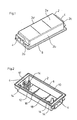
- connection and connection box on a housing cover 2 made of plastic.
- the housing cover 2 is formed by a substantially rectangular frame consisting of four side walls 2a to 2d and a closed cover plate 2e connecting the four side walls and running parallel to the solar module.
- the five-sided closed and downwardly open housing cover 2 is z.
- connection cable bushings 4 are each separate kink protection grommets 6 (see. FIG. 3 and FIG. 4 ) used.
- the housing cover 2 is open at the bottom and has an outwardly projecting mounting frame 8 with a circumferential adhesive groove 10, so that the housing cover 2 has a hat-like shape.
- the connection and connection box is finally permanently adhered to the solar module.
- the hat-shaped or trough-like shape of the housing cover forms an inner cavity 12, in which the in Fig. 2 not shown connecting devices are mounted in the assembled state substantially waterproof.
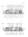
- the actuators 18, whose function will be explained in more detail below, are formed in this embodiment in the form of transverse actuating webs, which are integrally formed with the housing cover 2.
- connection devices 20 are two identical connection devices 20 are arranged in the housing 3 formed by the housing cover 2 and bottom member 50 of the connection and junction box 1. Since the two connection devices 20 are identical, only one of the two connection devices 20 will be referred to below.
- Fig. 3 shows the connection and junction box in the assembled state in which the contact terminal 22 is open.
- the bottom element 50 to which the connecting device 20 is attached has guide sleeves 15, in which the guide pins 14 are inserted.
- the guide pins 14 clamp in the associated guide sleeves 15, such that when placing the connection and junction box 1 on the solar module 24, the bottom member 50 is clamped to the housing cover 2, so that the housing 3 is taken on the housing cover 2 by a robot and automated can be placed without the bottom element 50 and the connecting device 20 fall out.
- the clamping between the guide pins 14 and the guide sleeves 15 is overcome by applying force to allow a relative displacement between the housing cover 2 and the bottom member 50 with the connecting device 20, namely, when a minimum force is exceeded.
- the guide sleeve 15 is slotted in this example in order to improve the overcoming clamping interaction with the guide pin 14.
- the connecting device 20 In the open mounting state, the connecting device 20 is not yet fully inserted into the housing cover 2 and the bottom element 50 protrudes a bit further (a few millimeters) from the housing cover 2 down, ie on the solar module side facing out. It consists in the assembled state Thus, an offset between the bottom 50a of the bottom member 50 and the mounting frame 8 of the housing cover 2, so that when placing the connection and junction box 1 first the bottom element 50 comes into contact with the solar module 24 and in this Fig. 3 shown state of the mounting frame 8 is still spaced from the surface 24 a of the solar module 24.
- the bottom element 50 has a relatively large opening 26 on its underside 50a facing the solar module 24. This ensures that the sensitive, flexible flat conductor strip 28, the so-called “ribbon”, can be introduced into the housing 3 and the connection device 20 without obstacle and resistance from below through the insertion opening 26 in the opened mounting state. As a result, the risk of damage to the flat conductor strip 28 is reduced.
- the contact terminal 22 defines in this state an open Einfangraum Society 31, in which the flat conductor strip 28 immersed without resistance when placing the connection and junction box from below. Preferably, no contact between the contact terminal 22 and the flat conductor strip 28 takes place in this state, so that the insertion and contacting of the flat conductor strip 28 takes place in two successive steps.
- the housing cover 2 is now subjected to force against the solar module 24, wherein the bottom element 50 is supported on the solar module 24.
- This condition is in Fig. 4 shown.
- the housing cover 2 is glued to the solar module by means of the adhesive located in the adhesive groove 10.
- the floor element 50 may but need not be glued to the solar module 24.
- the actuator 18, in this example, an actuating web with the clamping spring 32.
- the contact terminal 22 is closed by means of a pivoting movement of the clamping spring 32.
- the clamping portion 34 of the clamping spring 32 passes over the Einfangraum Scheme 31 and captures the upper end of the flat conductor strip 28 in order to clamp this between the clamping portion 34 of the clamping spring 32 and the counter-clamping member 36 electrically contacting.
- the flat conductor strip 28 is angled, since the counter-clamping element 36 is inclined in this example, approximately at 45 ° to the solar module normal.
- the clamping spring 32 has an actuating portion 38 which is divided into a curved portion 40 and a substantially straight portion 42.
- actuating portion 38 which is divided into a curved portion 40 and a substantially straight portion 42.
- connection device 20 also has a cable connection terminal 46 for the electrical connection cable, not shown.
- the cable connection terminal 46 is also provided with a clamping spring 48, but here also other connection variants, such. B. screw terminals are used.
- connection and junction box 1 comprises two identically formed connection devices 20 for simultaneously contacting two flat conductor strips 28.
- connection and junction box 1 also only one or more than two connection devices 20 may include.
- connection device 20 is fastened to the base element 50, which in this example is in the form of a dielectric carrier, preferably made of plastic.
- the underside 50a of the bottom element 50 defines the primary abutment surface to the solar module 24 and the insertion opening 26.
- the connecting device 20 further has a substantially U-shaped metallic support frame 51, preferably made of copper, which is latched to the bottom element 50 with latching hooks 52.
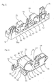
- FIGS. 5 and 6 show the contact terminal 22 in the closed contact state in which the contact terminal 22 is locked.
- the clamping spring 32 has two locking pins 54, which are engaged behind corresponding projections 55 in the metallic holding frame 51. In the locked state, the contact spring 32 is biased against the counter-clamp 36. This ensures one permanent and safe electrical contact.
- the flat conductor strip 28 is in the FIGS. 5 and 6 not shown.
- clamping spring 32 is suspended by means of bearing pin 56 in slotted bearing openings 58.
- the clamping spring 32 can be easily used in the manufacture of the connection and junction box and is secured due to the rotated in the assembled state and contact state relative to the slot 60 position of the flat bearing pin 56.
- the clamping spring 32 is stamped from sheet steel and bent substantially U-shaped.
- the metallic support frame 51 further includes an electrical connection element 64 for the bypass diode, which is supported on the base element 50 by means of a base 62.
- the clamping spring 32 Due to the shape of the two sections 40, 42 of the actuating portion 38 of the clamping spring 32, the clamping spring 32 is fixed in the open mounting state so that the Einfangraum Scheme 31 is kept open in the assembled state.
- the clamping spring 32 is forced to leave the open position, and is set in a pivoting movement.
- the flat conductor ribbon 28, which is located in the catching space region 31, is received by the clamping portion 34 and pressed by the continued pivotal movement at an angle of, in this example 45 °, against the counter-clamping element 36.
- the clamping spring engages with its locking lugs 54 in the contact or operating state ( Fig. 4 ) in the metallic support frame 51.
- FIG. 2 In this example, four guide pins 14 are provided in order to be able to arrange the connecting device 20 with the bottom element 50 at laterally different positions in the housing cover 2.
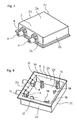
- FIGS. 7 and 8 show a connection and junction box 1 according to a second embodiment of the invention, in which the housing cover 2 is formed rather square to two connection devices 20 side by side rather than behind each other as in the first embodiment ( Fig. 1-6 ). Since the contact terminal 22 and the displacement device 14, 15 are formed in the first and second embodiments largely the same, reference is made to the above description of the first embodiment in order to avoid repetition.
- the underside of the cover plate 2e has a first actuating device 16 in the form of a lateral cam for actuating the reversing lever (in FIG Fig. 8 not shown, cf. For this Fig. 9-11 ). Furthermore, actuating pins 18 for actuating the contact terminals protrude from the cover plate 2e into the inner space 12 of the housing cover 2.
- the cam 16 and the actuating device 18 are in This embodiment is formed integrally with the housing cover 2.
- connection device 20 is arranged in the housing 3 of the connection and junction box 1, the connection device 20 is arranged.
- connection and junction box also has two identical connection devices 20, reference being made in the following to only one of the two.
- Fig. 9 shows the connection and junction box after it has been slipped over the flat conductor strip 28.
- the junction box is located when slipping in a first state, the mounting state in which the lever 21 is in a first position.
- the gap region 30 is kept free above the insertion opening 26 and the contact clamp 22 is opened.
- connection and junction box 1 has a relatively large insertion opening 26 on its side facing the solar module 24 underside. This ensures that the sensitive, flexible flat conductor strip 28, the so-called “ribbon", in the assembled state, is introduced from below into the connection and connection box 1 without obstacle and resistance. As a result, the risk of damage to the flat conductor strip 28 is reduced.
- the connection and junction box 1 defines in this state a located between the contact terminal 22 and the lever 21 open intermediate or Ein 1500raum Society 30, in which the flat conductor strip 28 immersed without resistance when placing the connection and junction box from below. Preferably takes place in this Condition still no contact between the contact terminal 22 or the reversing lever 21 and the flat conductor strip 28 instead.
- the housing cover 2 For contacting the flat conductor strip 28, the housing cover 2 is now subjected to force against the solar module 24, wherein the connection device 20 is supported on the solar module 24. This results in a linear relative displacement between the housing cover 2 and the bottom member 50 with the connecting device 20 to the effect that the housing cover 2 is pushed over the connecting device 20 until the mounting frame 8 with the adhesive located in the Klebstoffnut 10 adhesive (not shown) on the Surface of the solar module 24 comes to rest and the bottom 50 a of the bottom member 50 and the housing cover 2 abut flush with the solar module 24.
- This closed contact state represents the end or operating state and is in Fig. 11 shown. In the operating state, the housing 3 is glued to the solar module 24 by means of the adhesive located in the adhesive groove 10.
- connection and junction box 1 Before the connection and junction box 1 enters the final state, it still passes through in Fig. 10 illustrated intermediate state in which the flat conductor strip 28 is already bent and the contact terminal 22 is still open. Thus, the flat conductor strip 28 is first inserted into the insertion space area 30 when the connection and junction box 1 is placed. Subsequently, after the underside 50a of the floor element 50 has come to rest on the solar module 24, the flat conductor strip 28 is moved into the catchment area by means of the deflection lever 21 31 of the contact terminal 22 bent. Next, the contact terminal 22 is actively closed by means of the second actuating element 18. Thus, the junction box 1 defines three predefined states, namely the mounting state ( Fig.
- the first actuating element 16 in this example an actuating cam, interacts with the reversing lever 21 and subsequently the second actuating element 18, in this example an actuating pin, with the clamping spring 32.
- the bending portion 21a of the reversing lever 21 is deflected in response to an operation by means of the cam 16, and subsequently the contact terminal 22 is closed by a pivotal movement of the clamping spring 32.
- the cam 16 is formed in this example as a projection of the side wall of the housing cover 2 integral therewith.
- the bending portion 21a of the reversing lever 21 is integrally formed by means of a hinge hinge 21b with a holding portion 21c connected. Of the Retaining portion 21c is fixed to the bottom member 50, more precisely integrally formed therewith.
- connection and junction box 1 in this example comprises two connection devices 20.
- the connection devices 20 are fastened on the upper side to the dielectric base element 50.
- Fig. 12 shows the contact terminal 22 in the open mounting state.
- the clamping spring 32 has two locking pins 54, which are clamped in the open mounting state each in recesses 53 in the metallic support frame 51 surmountable.
- connection and junction box can have one or a plurality of contact terminals in order to connect one or a plurality of flat conductor strips in the connection and connection box to contact.
Landscapes
- Engineering & Computer Science (AREA)
- Architecture (AREA)
- Civil Engineering (AREA)
- Structural Engineering (AREA)
- Photovoltaic Devices (AREA)
- Connector Housings Or Holding Contact Members (AREA)
- Details Of Connecting Devices For Male And Female Coupling (AREA)
Abstract
Claims (14)
- Boîtier de raccordement et de connexion (1) pour un module solaire photovoltaïque (24) avec au moins une bande de conducteur plat (28), qui dépasse de la surface du module solaire, comprenant :un boîtier diélectrique (3) à placer sur le module solaire (24) et avec une ouverture d'introduction (26) sur le côté (50a) du boîtier (3) opposé au module solaire (24) à l'état monté pour l'introduction de la bande de conducteur plat (28) dans le boîtier (3),un dispositif de raccordement (20) hébergé par le boîtier (3) avec une borne de contact (22) pour établir un contact électrique avec la bande de conducteur plat (28) souple,le boîtier de raccordement et de connexion (1) définissant un état de montage et un état de contact,caractérisé en ce que :la borne de contact (22) est ouverte à l'état de montage afin de pouvoir introduire la bande de conducteur plat (28) souple dans la borne de contact (22) ouverte,la borne de contact (22) est fermée à l'état de contact afin d'établir un contact électrique avec la bande de conducteur plat (28) souple,le boîtier (3) est réalisé au moins en deux parties et les deux parties de boîtier (2, 50) peuvent être déplacées relativement l'une par rapport à l'autre, etle boîtier de raccordement et de connexion (1) présente un dispositif d'actionnement (18) afin de fermer la borne de contact (22), le dispositif d'actionnement (18) fermant automatiquement la borne de contact (22) en réponse à un mouvement relatif entre les deux parties de boîtier (2, 50) afin d'établir un contact avec la bande de conducteur plat (28) souple, lorsque le boîtier de raccordement et de connexion (1) est placé sur le module solaire (24) et la bande de conducteur plat (28) souple est introduite dans le boîtier (3).
- Boîtier de raccordement et de connexion (1) selon la revendication 1, le boîtier (3) présentant un dispositif de déplacement (14, 15), au moyen duquel les deux parties de boîtier (2, 50) peuvent être déplacées relativement l'une par rapport à l'autre transversalement à la surface (24a) du module solaire (24) et le dispositif d'actionnement (18) ferme automatiquement la borne de contact (22) en réponse à un déplacement relatif entre les deux parties de boîtier (2, 50) afin d'établir un contact avec la bande de conducteur plat (28) souple.
- Dispositif de raccordement et de connexion (1) selon la revendication 2, le dispositif de déplacement (14, 15) présentant une pluralité d'ergots de guidage (14) guidés dans des douilles de guidage (15), lesquels ergots sont prévus sur les deux parties de boîtier (2, 50).
- Dispositif de raccordement et de connexion (1) selon la revendication 2 ou 3, le dispositif de déplacement (14, 15) étant configuré de manière autobloquante à l'état de montage, de telle sorte que lors de la saisie et de la manipulation d'une seule des deux parties de boîtier (2), l'autre partie de boîtier (50) ne tombe pas.
- Dispositif de raccordement et de connexion (1) selon la revendication 2, 3 ou 4, la première (50) des deux parties de boîtier dépassant de la deuxième (2) des deux parties de boîtier à l'état de montage sur le côté opposé au module solaire, de telle sorte que, lors du placement du boîtier de raccordement et de connexion (1) sur le module solaire (24), tout d'abord seule la première partie de boîtier (50) vient prendre appui sur le module solaire (24), et par le biais de l'application d'une force sur la deuxième partie de boîtier (2) dans la direction du module solaire (24), le déplacement relatif de la deuxième partie de boîtier (2) par rapport à la première partie de boîtier (50) est provoqué afin de fermer la borne de contact (22) au moyen du dispositif d'actionnement (18).
- Boîtier de raccordement et de connexion (1) selon l'une des revendications précédentes, le boîtier (3) étant réalisé au moins en deux parties, et la première (50) des deux parties de boîtier étant réalisée en tant qu'élément inférieur pour prendre appui sur le module solaire, et la deuxième (2) des deux parties de boîtier étant réalisée en tant que partie supérieure, et au moins une des deux parties de boîtier (2, 50) présentant des parois latérales circonférentielles (2a-d), de sorte que les première et deuxième parties de boîtier (2, 50) définissent en commun, à l'exception d'ouvertures prédéfinies, un boîtier fermé et au moins étanche aux projections d'eau pour le dispositif de raccordement (1), lorsque le boîtier (3) est connecté de manière fixe au module solaire (24) à l'état de contact.
- Boîtier de raccordement et de connexion (1) selon la revendication 6, la partie supérieure (2) présentant un bord circonférentiel (8) avec une rainure adhésive (10) afin de coller la partie supérieure (2) sur la surface (24a) du module solaire (24).
- Boîtier de raccordement et de connexion (1) selon l'une des revendications précédentes, la borne de contact (22) étant réalisée en tant que borne élastique avec un ressort de serrage (32) et un élément de contre-serrage (36), la borne élastique étant ouverte en elle-même à l'état de montage et pouvant être fermée par le biais de l'application d'une force au moyen du dispositif d'actionnement (18).
- Boîtier de raccordement et de connexion (1) selon la revendication 8, le ressort de serrage (32) et/ou l'élément de contre-serrage (36) étant logés de manière pivotante sur le dispositif de raccordement (20), et le contact électrique avec la bande de conducteur plat (28) étant fermé au moyen d'un mouvement pivotant au moins du ressort (32) ou de l'élément de contre-serrage (36) en réponse à l'actionnement au moyen du dispositif d'actionnement (18).
- Boîtier de raccordement et de connexion (1) selon l'une des revendications précédentes, la borne de contact (22) présentant un mécanisme d'encliquetage (54, 55), au moyen duquel le ressort de serrage (32) est encliqueté à l'état de contact.
- Boîtier de raccordement et de connexion (1) selon l'une des revendications précédentes, lors du placement du boîtier de raccordement et de connexion, la bande de conducteur plat (28) souple étant introduite à travers l'ouverture d'introduction (26) pour l'essentiel sans résistance :soit directement dans la zone de capture (1) ouverte de la borne de contact (22) ouverte,soit dans une zone intermédiaire (30) ouverte dans le boîtier (3), et le boîtier de raccordement et de connexion (1) présentant un dispositif de déviation (21) pour la bande de conducteur plat (28) souple, qui dévie la bande de conducteur plat (28) souple de la zone intermédiaire (30) dans la zone de capture (31) de la borne de contact.
- Module solaire photovoltaïque (24) avec au moins une bande de conducteur plat (28) souple dépassant de la surface (24a), et au moins un boîtier de raccordement et de connexion (1) monté sur le module solaire (24) selon l'une des revendications précédentes.
- Procédé de raccordement d'un boîtier de raccordement et de connexion (1) à un module solaire photovoltaïque, comprenant les étapes de :préparation d'un module solaire (24) avec au moins une bande de conducteur plat (28) souple, qui dépasse de la surface (24a) du module solaire (24),préparation d'un boîtier de raccordement et de connexion (1), qui comprend un boîtier (3) ainsi qu'un dispositif de raccordement (20) disposé dans le boîtier (3) avec une borne de contact (22) électrique afin de produire un contact de serrage avec la bande de conducteur plat (28) souple, et présente une ouverture d'introduction (26) sur le côté inférieur du boîtier de raccordement et de connexion (1) ainsi qu'un dispositif d'actionnement (18) afin d'actionner la borne de contact (22),placement du boîtier de raccordement et de connexion (1) sur le module solaire (24), le boîtier de raccordement et de connexion (1) étant disposé avec l'ouverture d'introduction (26) par-dessus la bande de conducteur plat (28) souple,introduction de la bande de conducteur plat (28) souple dans la zone de capture (31) de la borne de contact (22) ouverte soit directement pendant ou soit après le placement du boîtier de raccordement et de connexion (1) par-dessus la bande de conducteur plat (28) souple,réalisation d'un mouvement relatif entre deux parties de boîtier (2, 50), moyennant quoi la borne de contact (22) est fermée au moyen du dispositif d'actionnement (18) et à cette occasion un contact est établi avec la bande de conducteur plat (28) souple.
- Procédé selon la revendication 13, le boîtier (3) comprenant un élément inférieur (50) et une partie supérieure (2), le dispositif de raccordement (20) étant fixé sur l'élément inférieur (50) et pouvant être déplacé conjointement avec l'élément inférieur (50) par rapport à la partie supérieure (2), le dispositif de déplacement (14, 15) étant prévu de manière surmontable et autobloquante, de sorte que l'élément inférieur (50) et le dispositif de raccordement (20) ne tombent pas de la partie supérieure (2) lors du placement du boîtier de raccordement et de connexion (1) sur le module solaire (24), l'élément inférieur (50) dépassant de la partie supérieure (2) vers le bas à l'état de montage, de sorte que lors du placement sur le module solaire (24) seul l'élément inférieur (50) est tout d'abord mis en appui avec la surface supérieure (24a) du module solaire (24),
une force étant appliquée sur la partie supérieure (2) dans la direction du module solaire (24), de telle sorte que la partie supérieure (2) est déplacée par rapport à l'élément inférieur (50) et au dispositif de raccordement (20), jusqu'à ce que la partie supérieure (2) prenne également appui sur le module solaire (24), la borne de contact (22) étant fermée automatiquement en réponse au déplacement relatif entre la partie supérieure (2) et l'élément inférieur (50).
Applications Claiming Priority (5)
| Application Number | Priority Date | Filing Date | Title |
|---|---|---|---|
| DE102007006433A DE102007006433A1 (de) | 2007-02-05 | 2007-02-05 | Anschlußbox für den elektrischen Anschluß eines Solarmoduls und Verfahren zur Montage einer Anschlußbox auf einem Solarmodul |
| DE102007037130A DE102007037130B3 (de) | 2007-08-07 | 2007-08-07 | Anschluss- und Verbindungsdose für ein Solarmodul |
| DE102007042547 | 2007-09-07 | ||
| DE102007051134A DE102007051134B4 (de) | 2007-09-07 | 2007-10-24 | Anschluss- und Verbindungsdose für ein Solarmodul |
| PCT/EP2008/000859 WO2008095670A1 (fr) | 2007-02-05 | 2008-02-04 | Boîtier de raccordement et de connexion pour un module solaire |
Publications (2)
| Publication Number | Publication Date |
|---|---|
| EP2118977A1 EP2118977A1 (fr) | 2009-11-18 |
| EP2118977B1 true EP2118977B1 (fr) | 2012-06-20 |
Family
ID=41153234
Family Applications (2)
| Application Number | Title | Priority Date | Filing Date |
|---|---|---|---|
| EP08707534A Not-in-force EP2118977B1 (fr) | 2007-02-05 | 2008-02-04 | Boîtier de raccordement et de connexion pour un module solaire |
| EP08707533A Withdrawn EP2115838A1 (fr) | 2007-02-05 | 2008-02-04 | Boîtier de raccordement et de connexion pour un module solaire |
Family Applications After (1)
| Application Number | Title | Priority Date | Filing Date |
|---|---|---|---|
| EP08707533A Withdrawn EP2115838A1 (fr) | 2007-02-05 | 2008-02-04 | Boîtier de raccordement et de connexion pour un module solaire |
Country Status (7)
| Country | Link |
|---|---|
| US (1) | US8366471B2 (fr) |
| EP (2) | EP2118977B1 (fr) |
| JP (1) | JP5441716B2 (fr) |
| CN (1) | CN101606293B (fr) |
| DK (1) | DK2118977T3 (fr) |
| ES (1) | ES2385112T3 (fr) |
| WO (2) | WO2008095670A1 (fr) |
Cited By (1)
| Publication number | Priority date | Publication date | Assignee | Title |
|---|---|---|---|---|
| DE102020100893A1 (de) | 2020-01-16 | 2021-07-22 | Phoenix Contact Gmbh & Co. Kg | Anschlussklemme |
Families Citing this family (30)
| Publication number | Priority date | Publication date | Assignee | Title |
|---|---|---|---|---|
| DE102008061268B4 (de) * | 2008-12-10 | 2017-02-23 | Phoenix Contact Gmbh & Co. Kg | Kontaktklemme und Verbinder mit Kontaktklemme |
| DE102008062034B4 (de) * | 2008-12-12 | 2010-08-12 | Tyco Electronics Amp Gmbh | Verbindungsvorrichtung zum Anschluss an ein Solarmodul und Solarmodul mit einer solchen Verbindungsvorrichtung |
| US8435056B2 (en) | 2009-04-16 | 2013-05-07 | Enphase Energy, Inc. | Apparatus for coupling power generated by a photovoltaic module to an output |
| JP5146406B2 (ja) * | 2009-05-27 | 2013-02-20 | 住友電装株式会社 | 太陽電池モジュール用端子ボックス |
| ATE536647T1 (de) | 2009-07-03 | 2011-12-15 | Tyco Elektronics Amp Gmbh | VERTEILERDOSE ZUM ANSCHLIEßEN EINER SOLARZELLE, ELEKTRISCHE DIODE, FÜHRUNGSELEMENT UND BEFESTIGUNGSMITTEL |
| CN102035157B (zh) * | 2009-09-25 | 2013-02-27 | 无锡尚德太阳能电力有限公司 | 一种太阳电池组件用接线盒及太阳电池组件 |
| CN101783488B (zh) * | 2010-01-19 | 2012-01-04 | 浙江大学 | 分离式太阳能组件接线盒 |
| WO2011109109A1 (fr) * | 2010-03-05 | 2011-09-09 | Xunlight Corporation | Ensemble borne comprenant une boîte de jonction pour un module photovoltaïque et procédé de formation de cet ensemble |
| CN103262350A (zh) * | 2010-12-09 | 2013-08-21 | 马尔遆公开股份有限公司 | 接触元件、特别是焊片,以及具有接触元件、特别是焊片的光伏接线盒 |
| WO2012083049A1 (fr) * | 2010-12-17 | 2012-06-21 | First Solar, Inc | Système de connexion électrique |
| DE102011009005B4 (de) * | 2011-01-14 | 2014-07-31 | Solon Se | Elektrische Anschlussdose für ein Photovoltaikmodul |
| DE102011004369B4 (de) * | 2011-02-18 | 2017-08-24 | SolarWorld Industries Thüringen GmbH | Anschlussdose und Satz von Anschlussdosen sowie Solarzellenanordnung |
| US9118273B2 (en) | 2011-07-18 | 2015-08-25 | Enphase Energy, Inc. | Resilient mounting assembly for photovoltaic modules |
| US20130048334A1 (en) * | 2011-08-29 | 2013-02-28 | Tyco Electronics Corporation | Junction box |
| KR101283628B1 (ko) * | 2011-09-05 | 2013-07-08 | 주식회사 씨엔플러스 | 정션박스 |
| JP5729648B2 (ja) * | 2011-10-13 | 2015-06-03 | ホシデン株式会社 | 太陽電池モジュール用端子ボックス |
| GB2502801B (en) * | 2012-06-07 | 2014-11-26 | Jaguar Land Rover Ltd | Insulating sock of a traction battery |
| USD734653S1 (en) | 2012-11-09 | 2015-07-21 | Enphase Energy, Inc. | AC module mounting bracket |
| US10402922B2 (en) * | 2014-04-10 | 2019-09-03 | Vivint Solar, Inc. | Photovoltaic system installation |
| CN103944504A (zh) * | 2014-04-25 | 2014-07-23 | 江苏九鼎光伏系统有限公司 | 接插式光伏电池组件接线盒及其接线安装方法 |
| JP6283278B2 (ja) * | 2014-07-18 | 2018-02-21 | ホシデン株式会社 | 端子ボックス及び出力線の接続方法 |
| JP6156308B2 (ja) * | 2014-09-24 | 2017-07-05 | 住友電装株式会社 | 電気接続箱 |
| US10476429B2 (en) | 2015-06-29 | 2019-11-12 | Te Connectivity Corporation | Solar junction box |
| JP6726074B2 (ja) | 2016-09-30 | 2020-07-22 | オムロン株式会社 | 端子台 |
| EP3723204B1 (fr) * | 2017-12-06 | 2023-12-13 | Zeon Corporation | Dispositif de connexion |
| USD879040S1 (en) * | 2018-04-03 | 2020-03-24 | Electro Expo Limited | Electrical connection box |
| CN110336232B (zh) * | 2019-07-24 | 2020-10-02 | 扬州利家科技有限公司 | 一种接线效率高的防爆接线盒 |
| CN113161954B (zh) * | 2021-03-31 | 2022-09-30 | 商丘工学院 | 一种电气工程用电缆配接器装置 |
| FR3128066B1 (fr) * | 2021-10-07 | 2024-09-13 | Tyco Electronics France Sas | Dispositif de connexion électrique |
| CN120221221B (zh) * | 2025-05-26 | 2025-08-12 | 聚变新能(安徽)有限公司 | 一种接电板、馈电接头、馈电接头保护机构以及真空压力浸渍模具 |
Family Cites Families (19)
| Publication number | Priority date | Publication date | Assignee | Title |
|---|---|---|---|---|
| US4460232A (en) * | 1982-05-24 | 1984-07-17 | Amp, Incorporated | Junction box for solar modules |
| JP3424559B2 (ja) * | 1998-08-20 | 2003-07-07 | 住友電装株式会社 | 太陽電池モジュールの端子ボックスおよびその端子ボックスを用いた配線システム |
| JP3838789B2 (ja) * | 1998-09-11 | 2006-10-25 | 旭化成建材株式会社 | 太陽電池モジュール、太陽電池モジュールの作成方法、太陽電池モジュールの取り付け構造、および太陽電池付き屋根材 |
| JP4080607B2 (ja) * | 1998-09-16 | 2008-04-23 | スタンレー電気株式会社 | Led取付装置 |
| EP1102354B1 (fr) * | 1999-11-17 | 2008-05-28 | Tyco Electronics AMP GmbH | Dispositif pour contacter des conducteurs à feuille, en particulier d'un module solaire |
| JP2002359389A (ja) | 2001-05-31 | 2002-12-13 | Kitani Denki Kk | 太陽光発電モジュール配線用端子ボックス |
| DE20311184U1 (de) | 2003-07-21 | 2004-02-19 | Tyco Electronics Amp Gmbh | Anschlussdose zum Anschließen an ein Solarpaneel |
| DE10358140B4 (de) * | 2003-12-10 | 2006-01-05 | Günther Spelsberg GmbH & Co. KG | Elektrische Anschluß- und Verbindungsdose für ein Solarzellenmodul |
| JP4798956B2 (ja) * | 2004-03-29 | 2011-10-19 | 京セラ株式会社 | 太陽電池モジュールおよびそれを用いた太陽光発電装置 |
| DE102004020958B3 (de) | 2004-04-28 | 2005-08-25 | Rose Systemtechnik Gmbh | Anschlußklemme und damit gebildete Anschlußbox |
| JP3767618B2 (ja) * | 2004-08-19 | 2006-04-19 | 住友電装株式会社 | 太陽電池モジュール用端子ボックス |
| ES2371638T3 (es) | 2004-12-16 | 2012-01-05 | Günther Spelsberg GmbH & Co. KG | Caja de conexión y unión eléctrica para un módulo de células solares. |
| JP2006278425A (ja) | 2005-03-28 | 2006-10-12 | Sharp Corp | 太陽光発電システム |
| DE102005025632B4 (de) | 2005-06-03 | 2015-09-17 | Te Connectivity Germany Gmbh | Verbindungsvorrichtung für den Anschluss elektrischer Folienleiter |
| DE202005018884U1 (de) | 2005-12-02 | 2006-02-09 | Multi-Holding Ag | Anschlussdose für ein Solarpaneel sowie Solarpaneel mit einer solchen Anschlussdose |
| DE502007005412D1 (de) | 2006-04-13 | 2010-12-02 | Weidmueller Interface | Elektrische Anschlussvorrichtung für Flachleiter |
| DE202007005126U1 (de) * | 2007-04-04 | 2008-08-14 | Weidmüller Interface GmbH & Co. KG | Elektrische Anschlußvorrichtung für Kontakte, insbesondere Messerkontakte |
| ATE540564T1 (de) * | 2008-08-29 | 2012-01-15 | Heyco Inc | Anschlussdose für fotovoltaiksysteme |
| DE202009004930U1 (de) * | 2008-09-22 | 2010-03-04 | Weidmüller Interface GmbH & Co. KG | Elektrische Anschlussvorrichtung für Flachleiter |
-
2008
- 2008-02-04 EP EP08707534A patent/EP2118977B1/fr not_active Not-in-force
- 2008-02-04 EP EP08707533A patent/EP2115838A1/fr not_active Withdrawn
- 2008-02-04 US US12/525,794 patent/US8366471B2/en not_active Expired - Fee Related
- 2008-02-04 DK DK08707534.7T patent/DK2118977T3/da active
- 2008-02-04 WO PCT/EP2008/000859 patent/WO2008095670A1/fr not_active Ceased
- 2008-02-04 WO PCT/EP2008/000858 patent/WO2008095669A1/fr not_active Ceased
- 2008-02-04 CN CN2008800040872A patent/CN101606293B/zh not_active Expired - Fee Related
- 2008-02-04 ES ES08707534T patent/ES2385112T3/es active Active
- 2008-02-04 JP JP2009548614A patent/JP5441716B2/ja not_active Expired - Fee Related
Cited By (1)
| Publication number | Priority date | Publication date | Assignee | Title |
|---|---|---|---|---|
| DE102020100893A1 (de) | 2020-01-16 | 2021-07-22 | Phoenix Contact Gmbh & Co. Kg | Anschlussklemme |
Also Published As
| Publication number | Publication date |
|---|---|
| US8366471B2 (en) | 2013-02-05 |
| DK2118977T3 (da) | 2012-10-01 |
| WO2008095670A1 (fr) | 2008-08-14 |
| WO2008095669A1 (fr) | 2008-08-14 |
| US20100173511A1 (en) | 2010-07-08 |
| ES2385112T3 (es) | 2012-07-18 |
| CN101606293B (zh) | 2013-11-13 |
| EP2118977A1 (fr) | 2009-11-18 |
| JP5441716B2 (ja) | 2014-03-12 |
| JP2010518614A (ja) | 2010-05-27 |
| CN101606293A (zh) | 2009-12-16 |
| EP2115838A1 (fr) | 2009-11-11 |
| WO2008095670A8 (fr) | 2012-03-01 |
Similar Documents
| Publication | Publication Date | Title |
|---|---|---|
| EP2118977B1 (fr) | Boîtier de raccordement et de connexion pour un module solaire | |
| DE102007051134B4 (de) | Anschluss- und Verbindungsdose für ein Solarmodul | |
| DE102007037130B3 (de) | Anschluss- und Verbindungsdose für ein Solarmodul | |
| WO2008095668A1 (fr) | Boîtier de raccordement et de connexion pour un module solaire | |
| DE102008003448B4 (de) | Anschlußdose, Verwendung, Solarpaneel, Kontaktelement, und Verfahren | |
| EP2201609B1 (fr) | Boîte de jonction, panneau solaire avec une telle boîte de jonction et procédé pour brancher la boîte de jonction avec le panneau solaire | |
| DE102009033481B4 (de) | Anschluss- und Verbindungsvorrichtung | |
| DE69333735T2 (de) | Photovoltaisches dachbedeckungssystem | |
| EP1941550B1 (fr) | Systeme a energie solaire comprenant une pluralite de modules photovoltaiques | |
| DE102010029714A1 (de) | Elektrische Federklemmeinrichtung, Stanzgitter, Stromschiene und elektrische Anschlussvorrichtung | |
| DE102010024350A1 (de) | Anschlusseinrichtung für Photovoltaikmodule und Verfahren zu deren Montage | |
| DE102012102214B3 (de) | Solarmodul mit Anschlusselementen, Solarmodulsystem und Verfahren zur Montage und Verbindung eines Solarmoduls | |
| DE102007032603A1 (de) | Anschlußkontakt und Verfahren zum Laminieren von mit elektrischen Anschlußkontakten versehenen Gegenständen | |
| DE202010000052U1 (de) | Photovoltaikmodul mit einer Anschlussdose | |
| EP2296181B1 (fr) | Boîte de jonction, son utilisation dans un panneau solaire et procédé de fabrication | |
| EP2386125B1 (fr) | Panneau solaire et procédé pour sa fabrication | |
| DE102013209839A1 (de) | Verbindungsanordnung an einer Solarzelleneinheit und Stromerzeugungseinheit | |
| EP2549552A2 (fr) | Module de cellule solaire et agencement de cellules solaires | |
| WO2010054839A1 (fr) | Module de connexion pour panneaux solaires présentant une ligne de connexion préfabriquée | |
| EP2356698B1 (fr) | Panneau solaire, procédé de fabrication de ce panneau solaire et boîtier de pontage | |
| EP2674988B1 (fr) | Prise de panneau photovoltaïque avec contact par serrage des petites bandes de l'élément solaire | |
| DE102010023772A1 (de) | Anschlussdose für ein photovoltaisches Solarmodul | |
| DE102011011715A1 (de) | Anschlußdose, Verfahren zum Herstellen sowie Verwendung der Anschlußdose | |
| DE102018215494A1 (de) | Haltevorrichtung für ein Solarmodul, Anordnung sowie Verfahren zur Herstellung einer Anordnung | |
| EP2806440A1 (fr) | Panneau photovoltaïque couleur pouvant être connecté, réseau de panneaux photovoltaïques couleurs pouvant être connectés et procédé de fabrication du réseau |
Legal Events
| Date | Code | Title | Description |
|---|---|---|---|
| PUAI | Public reference made under article 153(3) epc to a published international application that has entered the european phase |
Free format text: ORIGINAL CODE: 0009012 |
|
| 17P | Request for examination filed |
Effective date: 20090722 |
|
| AK | Designated contracting states |
Kind code of ref document: A1 Designated state(s): AT BE BG CH CY CZ DE DK EE ES FI FR GB GR HR HU IE IS IT LI LT LU LV MC MT NL NO PL PT RO SE SI SK TR |
|
| RIN1 | Information on inventor provided before grant (corrected) |
Inventor name: GIEFERS, STEFAN |
|
| DAX | Request for extension of the european patent (deleted) | ||
| 17Q | First examination report despatched |
Effective date: 20110408 |
|
| REG | Reference to a national code |
Ref country code: DE Ref legal event code: R079 Ref document number: 502008007476 Country of ref document: DE Free format text: PREVIOUS MAIN CLASS: H02G0003160000 Ipc: H01R0004480000 |
|
| RIC1 | Information provided on ipc code assigned before grant |
Ipc: H01R 4/48 20060101AFI20111212BHEP Ipc: H01L 31/048 20060101ALN20111212BHEP |
|
| GRAP | Despatch of communication of intention to grant a patent |
Free format text: ORIGINAL CODE: EPIDOSNIGR1 |
|
| GRAS | Grant fee paid |
Free format text: ORIGINAL CODE: EPIDOSNIGR3 |
|
| GRAA | (expected) grant |
Free format text: ORIGINAL CODE: 0009210 |
|
| AK | Designated contracting states |
Kind code of ref document: B1 Designated state(s): AT BE BG CH CY CZ DE DK EE ES FI FR GB GR HR HU IE IS IT LI LT LU LV MC MT NL NO PL PT RO SE SI SK TR |
|
| REG | Reference to a national code |
Ref country code: GB Ref legal event code: FG4D Free format text: NOT ENGLISH |
|
| REG | Reference to a national code |
Ref country code: SE Ref legal event code: TRGR |
|
| REG | Reference to a national code |
Ref country code: CH Ref legal event code: EP Ref country code: CH Ref legal event code: NV Representative=s name: BOVARD AG |
|
| REG | Reference to a national code |
Ref country code: AT Ref legal event code: REF Ref document number: 563494 Country of ref document: AT Kind code of ref document: T Effective date: 20120715 |
|
| REG | Reference to a national code |
Ref country code: IE Ref legal event code: FG4D Free format text: LANGUAGE OF EP DOCUMENT: GERMAN Ref country code: ES Ref legal event code: FG2A Ref document number: 2385112 Country of ref document: ES Kind code of ref document: T3 Effective date: 20120718 |
|
| REG | Reference to a national code |
Ref country code: DE Ref legal event code: R096 Ref document number: 502008007476 Country of ref document: DE Effective date: 20120816 |
|
| REG | Reference to a national code |
Ref country code: DK Ref legal event code: T3 |
|
| REG | Reference to a national code |
Ref country code: NL Ref legal event code: T3 |
|
| PG25 | Lapsed in a contracting state [announced via postgrant information from national office to epo] |
Ref country code: LT Free format text: LAPSE BECAUSE OF FAILURE TO SUBMIT A TRANSLATION OF THE DESCRIPTION OR TO PAY THE FEE WITHIN THE PRESCRIBED TIME-LIMIT Effective date: 20120620 Ref country code: FI Free format text: LAPSE BECAUSE OF FAILURE TO SUBMIT A TRANSLATION OF THE DESCRIPTION OR TO PAY THE FEE WITHIN THE PRESCRIBED TIME-LIMIT Effective date: 20120620 Ref country code: NO Free format text: LAPSE BECAUSE OF FAILURE TO SUBMIT A TRANSLATION OF THE DESCRIPTION OR TO PAY THE FEE WITHIN THE PRESCRIBED TIME-LIMIT Effective date: 20120920 |
|
| REG | Reference to a national code |
Ref country code: LT Ref legal event code: MG4D Effective date: 20120620 |
|
| PG25 | Lapsed in a contracting state [announced via postgrant information from national office to epo] |
Ref country code: LV Free format text: LAPSE BECAUSE OF FAILURE TO SUBMIT A TRANSLATION OF THE DESCRIPTION OR TO PAY THE FEE WITHIN THE PRESCRIBED TIME-LIMIT Effective date: 20120620 Ref country code: HR Free format text: LAPSE BECAUSE OF FAILURE TO SUBMIT A TRANSLATION OF THE DESCRIPTION OR TO PAY THE FEE WITHIN THE PRESCRIBED TIME-LIMIT Effective date: 20120620 Ref country code: GR Free format text: LAPSE BECAUSE OF FAILURE TO SUBMIT A TRANSLATION OF THE DESCRIPTION OR TO PAY THE FEE WITHIN THE PRESCRIBED TIME-LIMIT Effective date: 20120921 Ref country code: SI Free format text: LAPSE BECAUSE OF FAILURE TO SUBMIT A TRANSLATION OF THE DESCRIPTION OR TO PAY THE FEE WITHIN THE PRESCRIBED TIME-LIMIT Effective date: 20120620 |
|
| PG25 | Lapsed in a contracting state [announced via postgrant information from national office to epo] |
Ref country code: CZ Free format text: LAPSE BECAUSE OF FAILURE TO SUBMIT A TRANSLATION OF THE DESCRIPTION OR TO PAY THE FEE WITHIN THE PRESCRIBED TIME-LIMIT Effective date: 20120620 Ref country code: SK Free format text: LAPSE BECAUSE OF FAILURE TO SUBMIT A TRANSLATION OF THE DESCRIPTION OR TO PAY THE FEE WITHIN THE PRESCRIBED TIME-LIMIT Effective date: 20120620 Ref country code: EE Free format text: LAPSE BECAUSE OF FAILURE TO SUBMIT A TRANSLATION OF THE DESCRIPTION OR TO PAY THE FEE WITHIN THE PRESCRIBED TIME-LIMIT Effective date: 20120620 Ref country code: IS Free format text: LAPSE BECAUSE OF FAILURE TO SUBMIT A TRANSLATION OF THE DESCRIPTION OR TO PAY THE FEE WITHIN THE PRESCRIBED TIME-LIMIT Effective date: 20121020 Ref country code: RO Free format text: LAPSE BECAUSE OF FAILURE TO SUBMIT A TRANSLATION OF THE DESCRIPTION OR TO PAY THE FEE WITHIN THE PRESCRIBED TIME-LIMIT Effective date: 20120620 Ref country code: CY Free format text: LAPSE BECAUSE OF FAILURE TO SUBMIT A TRANSLATION OF THE DESCRIPTION OR TO PAY THE FEE WITHIN THE PRESCRIBED TIME-LIMIT Effective date: 20120620 |
|
| PG25 | Lapsed in a contracting state [announced via postgrant information from national office to epo] |
Ref country code: PL Free format text: LAPSE BECAUSE OF FAILURE TO SUBMIT A TRANSLATION OF THE DESCRIPTION OR TO PAY THE FEE WITHIN THE PRESCRIBED TIME-LIMIT Effective date: 20120620 Ref country code: PT Free format text: LAPSE BECAUSE OF FAILURE TO SUBMIT A TRANSLATION OF THE DESCRIPTION OR TO PAY THE FEE WITHIN THE PRESCRIBED TIME-LIMIT Effective date: 20121022 |
|
| PLBE | No opposition filed within time limit |
Free format text: ORIGINAL CODE: 0009261 |
|
| STAA | Information on the status of an ep patent application or granted ep patent |
Free format text: STATUS: NO OPPOSITION FILED WITHIN TIME LIMIT |
|
| 26N | No opposition filed |
Effective date: 20130321 |
|
| REG | Reference to a national code |
Ref country code: DE Ref legal event code: R097 Ref document number: 502008007476 Country of ref document: DE Effective date: 20130321 |
|
| PG25 | Lapsed in a contracting state [announced via postgrant information from national office to epo] |
Ref country code: BG Free format text: LAPSE BECAUSE OF FAILURE TO SUBMIT A TRANSLATION OF THE DESCRIPTION OR TO PAY THE FEE WITHIN THE PRESCRIBED TIME-LIMIT Effective date: 20120920 |
|
| BERE | Be: lapsed |
Owner name: PHOENIX CONTACT G.M.B.H. & CO. KG Effective date: 20130228 |
|
| PG25 | Lapsed in a contracting state [announced via postgrant information from national office to epo] |
Ref country code: MC Free format text: LAPSE BECAUSE OF NON-PAYMENT OF DUE FEES Effective date: 20130228 |
|
| REG | Reference to a national code |
Ref country code: IE Ref legal event code: MM4A |
|
| PG25 | Lapsed in a contracting state [announced via postgrant information from national office to epo] |
Ref country code: IE Free format text: LAPSE BECAUSE OF NON-PAYMENT OF DUE FEES Effective date: 20130204 Ref country code: BE Free format text: LAPSE BECAUSE OF NON-PAYMENT OF DUE FEES Effective date: 20130228 |
|
| PGFP | Annual fee paid to national office [announced via postgrant information from national office to epo] |
Ref country code: SE Payment date: 20140224 Year of fee payment: 7 Ref country code: NL Payment date: 20140224 Year of fee payment: 7 Ref country code: DK Payment date: 20140224 Year of fee payment: 7 Ref country code: CH Payment date: 20140227 Year of fee payment: 7 |
|
| PGFP | Annual fee paid to national office [announced via postgrant information from national office to epo] |
Ref country code: AT Payment date: 20140224 Year of fee payment: 7 |
|
| PG25 | Lapsed in a contracting state [announced via postgrant information from national office to epo] |
Ref country code: MT Free format text: LAPSE BECAUSE OF FAILURE TO SUBMIT A TRANSLATION OF THE DESCRIPTION OR TO PAY THE FEE WITHIN THE PRESCRIBED TIME-LIMIT Effective date: 20120620 |
|
| REG | Reference to a national code |
Ref country code: FR Ref legal event code: PLFP Year of fee payment: 8 |
|
| PGFP | Annual fee paid to national office [announced via postgrant information from national office to epo] |
Ref country code: ES Payment date: 20150205 Year of fee payment: 8 Ref country code: IT Payment date: 20150225 Year of fee payment: 8 |
|
| PGFP | Annual fee paid to national office [announced via postgrant information from national office to epo] |
Ref country code: FR Payment date: 20150223 Year of fee payment: 8 Ref country code: GB Payment date: 20150220 Year of fee payment: 8 |
|
| PG25 | Lapsed in a contracting state [announced via postgrant information from national office to epo] |
Ref country code: TR Free format text: LAPSE BECAUSE OF FAILURE TO SUBMIT A TRANSLATION OF THE DESCRIPTION OR TO PAY THE FEE WITHIN THE PRESCRIBED TIME-LIMIT Effective date: 20120620 |
|
| PG25 | Lapsed in a contracting state [announced via postgrant information from national office to epo] |
Ref country code: HU Free format text: LAPSE BECAUSE OF FAILURE TO SUBMIT A TRANSLATION OF THE DESCRIPTION OR TO PAY THE FEE WITHIN THE PRESCRIBED TIME-LIMIT; INVALID AB INITIO Effective date: 20080204 Ref country code: LU Free format text: LAPSE BECAUSE OF NON-PAYMENT OF DUE FEES Effective date: 20130204 |
|
| REG | Reference to a national code |
Ref country code: NL Ref legal event code: V1 Effective date: 20150901 |
|
| REG | Reference to a national code |
Ref country code: DK Ref legal event code: EBP Effective date: 20150228 |
|
| REG | Reference to a national code |
Ref country code: SE Ref legal event code: EUG |
|
| PG25 | Lapsed in a contracting state [announced via postgrant information from national office to epo] |
Ref country code: NL Free format text: LAPSE BECAUSE OF NON-PAYMENT OF DUE FEES Effective date: 20150901 |
|
| REG | Reference to a national code |
Ref country code: CH Ref legal event code: PL |
|
| REG | Reference to a national code |
Ref country code: AT Ref legal event code: MM01 Ref document number: 563494 Country of ref document: AT Kind code of ref document: T Effective date: 20150204 |
|
| PG25 | Lapsed in a contracting state [announced via postgrant information from national office to epo] |
Ref country code: LI Free format text: LAPSE BECAUSE OF NON-PAYMENT OF DUE FEES Effective date: 20150228 Ref country code: CH Free format text: LAPSE BECAUSE OF NON-PAYMENT OF DUE FEES Effective date: 20150228 |
|
| PG25 | Lapsed in a contracting state [announced via postgrant information from national office to epo] |
Ref country code: SE Free format text: LAPSE BECAUSE OF NON-PAYMENT OF DUE FEES Effective date: 20150205 Ref country code: AT Free format text: LAPSE BECAUSE OF NON-PAYMENT OF DUE FEES Effective date: 20150204 |
|
| PG25 | Lapsed in a contracting state [announced via postgrant information from national office to epo] |
Ref country code: DK Free format text: LAPSE BECAUSE OF NON-PAYMENT OF DUE FEES Effective date: 20150228 |
|
| GBPC | Gb: european patent ceased through non-payment of renewal fee |
Effective date: 20160204 |
|
| REG | Reference to a national code |
Ref country code: FR Ref legal event code: ST Effective date: 20161028 |
|
| PG25 | Lapsed in a contracting state [announced via postgrant information from national office to epo] |
Ref country code: IT Free format text: LAPSE BECAUSE OF NON-PAYMENT OF DUE FEES Effective date: 20160204 |
|
| PG25 | Lapsed in a contracting state [announced via postgrant information from national office to epo] |
Ref country code: FR Free format text: LAPSE BECAUSE OF NON-PAYMENT OF DUE FEES Effective date: 20160229 Ref country code: GB Free format text: LAPSE BECAUSE OF NON-PAYMENT OF DUE FEES Effective date: 20160204 |
|
| PGFP | Annual fee paid to national office [announced via postgrant information from national office to epo] |
Ref country code: DE Payment date: 20170428 Year of fee payment: 10 |
|
| PG25 | Lapsed in a contracting state [announced via postgrant information from national office to epo] |
Ref country code: ES Free format text: LAPSE BECAUSE OF NON-PAYMENT OF DUE FEES Effective date: 20160205 |
|
| REG | Reference to a national code |
Ref country code: DE Ref legal event code: R119 Ref document number: 502008007476 Country of ref document: DE |
|
| REG | Reference to a national code |
Ref country code: ES Ref legal event code: FD2A Effective date: 20181207 |
|
| PG25 | Lapsed in a contracting state [announced via postgrant information from national office to epo] |
Ref country code: DE Free format text: LAPSE BECAUSE OF NON-PAYMENT OF DUE FEES Effective date: 20180901 |