EP2201609B1 - Boîte de jonction, panneau solaire avec une telle boîte de jonction et procédé pour brancher la boîte de jonction avec le panneau solaire - Google Patents
Boîte de jonction, panneau solaire avec une telle boîte de jonction et procédé pour brancher la boîte de jonction avec le panneau solaire Download PDFInfo
- Publication number
- EP2201609B1 EP2201609B1 EP08802058.1A EP08802058A EP2201609B1 EP 2201609 B1 EP2201609 B1 EP 2201609B1 EP 08802058 A EP08802058 A EP 08802058A EP 2201609 B1 EP2201609 B1 EP 2201609B1
- Authority
- EP
- European Patent Office
- Prior art keywords
- contact
- contact spring
- force
- connection box
- terminal
- Prior art date
- Legal status (The legal status is an assumption and is not a legal conclusion. Google has not performed a legal analysis and makes no representation as to the accuracy of the status listed.)
- Not-in-force
Links
- 238000000034 method Methods 0.000 title claims description 17
- 239000004020 conductor Substances 0.000 claims description 99
- 238000003780 insertion Methods 0.000 claims description 77
- 230000037431 insertion Effects 0.000 claims description 77
- 230000001070 adhesive effect Effects 0.000 claims description 24
- 239000000853 adhesive Substances 0.000 claims description 23
- 230000003213 activating effect Effects 0.000 claims description 3
- 230000004913 activation Effects 0.000 description 3
- 239000002655 kraft paper Substances 0.000 description 3
- 239000002184 metal Substances 0.000 description 3
- 238000005452 bending Methods 0.000 description 2
- 230000000903 blocking effect Effects 0.000 description 2
- 230000001419 dependent effect Effects 0.000 description 2
- 230000000694 effects Effects 0.000 description 2
- 239000007788 liquid Substances 0.000 description 2
- 229920000642 polymer Polymers 0.000 description 2
- 238000003825 pressing Methods 0.000 description 2
- 229920003002 synthetic resin Polymers 0.000 description 2
- 239000000057 synthetic resin Substances 0.000 description 2
- 239000002390 adhesive tape Substances 0.000 description 1
- 238000012790 confirmation Methods 0.000 description 1
- 238000005520 cutting process Methods 0.000 description 1
- 230000007423 decrease Effects 0.000 description 1
- 239000012777 electrically insulating material Substances 0.000 description 1
- 239000003292 glue Substances 0.000 description 1
- 238000010438 heat treatment Methods 0.000 description 1
- 238000009434 installation Methods 0.000 description 1
- 238000004519 manufacturing process Methods 0.000 description 1
- 229910001092 metal group alloy Inorganic materials 0.000 description 1
- 230000001681 protective effect Effects 0.000 description 1
- 230000002787 reinforcement Effects 0.000 description 1
- 229920005989 resin Polymers 0.000 description 1
- 239000011347 resin Substances 0.000 description 1
- 239000007787 solid Substances 0.000 description 1
- 238000005507 spraying Methods 0.000 description 1
- 238000003756 stirring Methods 0.000 description 1
Images


Classifications
-
- H—ELECTRICITY
- H01—ELECTRIC ELEMENTS
- H01R—ELECTRICALLY-CONDUCTIVE CONNECTIONS; STRUCTURAL ASSOCIATIONS OF A PLURALITY OF MUTUALLY-INSULATED ELECTRICAL CONNECTING ELEMENTS; COUPLING DEVICES; CURRENT COLLECTORS
- H01R4/00—Electrically-conductive connections between two or more conductive members in direct contact, i.e. touching one another; Means for effecting or maintaining such contact; Electrically-conductive connections having two or more spaced connecting locations for conductors and using contact members penetrating insulation
- H01R4/28—Clamped connections, spring connections
- H01R4/48—Clamped connections, spring connections utilising a spring, clip, or other resilient member
- H01R4/4809—Clamped connections, spring connections utilising a spring, clip, or other resilient member using a leaf spring to bias the conductor toward the busbar
- H01R4/48185—Clamped connections, spring connections utilising a spring, clip, or other resilient member using a leaf spring to bias the conductor toward the busbar adapted for axial insertion of a wire end
- H01R4/48275—Clamped connections, spring connections utilising a spring, clip, or other resilient member using a leaf spring to bias the conductor toward the busbar adapted for axial insertion of a wire end with an opening in the housing for insertion of a release tool
-
- H—ELECTRICITY
- H02—GENERATION; CONVERSION OR DISTRIBUTION OF ELECTRIC POWER
- H02S—GENERATION OF ELECTRIC POWER BY CONVERSION OF INFRARED RADIATION, VISIBLE LIGHT OR ULTRAVIOLET LIGHT, e.g. USING PHOTOVOLTAIC [PV] MODULES
- H02S40/00—Components or accessories in combination with PV modules, not provided for in groups H02S10/00 - H02S30/00
- H02S40/30—Electrical components
- H02S40/34—Electrical components comprising specially adapted electrical connection means to be structurally associated with the PV module, e.g. junction boxes
-
- Y—GENERAL TAGGING OF NEW TECHNOLOGICAL DEVELOPMENTS; GENERAL TAGGING OF CROSS-SECTIONAL TECHNOLOGIES SPANNING OVER SEVERAL SECTIONS OF THE IPC; TECHNICAL SUBJECTS COVERED BY FORMER USPC CROSS-REFERENCE ART COLLECTIONS [XRACs] AND DIGESTS
- Y02—TECHNOLOGIES OR APPLICATIONS FOR MITIGATION OR ADAPTATION AGAINST CLIMATE CHANGE
- Y02E—REDUCTION OF GREENHOUSE GAS [GHG] EMISSIONS, RELATED TO ENERGY GENERATION, TRANSMISSION OR DISTRIBUTION
- Y02E10/00—Energy generation through renewable energy sources
- Y02E10/50—Photovoltaic [PV] energy
-
- Y—GENERAL TAGGING OF NEW TECHNOLOGICAL DEVELOPMENTS; GENERAL TAGGING OF CROSS-SECTIONAL TECHNOLOGIES SPANNING OVER SEVERAL SECTIONS OF THE IPC; TECHNICAL SUBJECTS COVERED BY FORMER USPC CROSS-REFERENCE ART COLLECTIONS [XRACs] AND DIGESTS
- Y10—TECHNICAL SUBJECTS COVERED BY FORMER USPC
- Y10T—TECHNICAL SUBJECTS COVERED BY FORMER US CLASSIFICATION
- Y10T29/00—Metal working
- Y10T29/49—Method of mechanical manufacture
- Y10T29/49002—Electrical device making
- Y10T29/49117—Conductor or circuit manufacturing
- Y10T29/49174—Assembling terminal to elongated conductor
Definitions
- the invention relates to a junction box, a solar panel, a contact device and a method.
- Conventional solar modules for generating electrical energy from sunlight comprise one or more individual solar cells. Depending on the desired voltage and / or current to be provided by the solar module, individual solar cells within the module are connected in parallel and / or in series and thus combined to form solar cell groups. The solar cell groups are combined to form a flat solar module. The electrical connections of the solar cell groups of the solar module are led to the outside.
- partial reduction of the irradiation intensity by sunlight to individual solar cells or solar cell groups for example due to soiling or shadows
- the following effects can occur, inter alia: (1) A (uniform) reduction of the irradiation intensity within the interconnected solar cell groups leads to a reduction in the performance of the respective solar cell group.
- this shaded solar cell acts as a blocking diode or resistance within the circuit of the solar cell group, which may lead to the fact that the entire solar cell group can no longer provide electrical energy and on the other to damage the shaded solar cell and thus can lead to permanent failure of the solar cell group.
- different voltages can be present between the lead-out terminals of the solar cell groups of a solar module, depending on the irradiation intensity on the individual solar cell.
- bypass diodes are used, which are electrically connected in anti-parallel to the solar cell groups. These bypass diodes have the effect of passing the flow of current through the solar module past solar cell groups which provide low power, i.
- the connections of this solar cell group of a solar module are short-circuited by the bypass diode and the corresponding solar cell group bridged thereby.
- Solar panels in addition to the solar module usually include an electrical junction box with at least two contact devices and at least one bypass diode.
- the solar cells in a solar module are usually connected to each other by flat thin conductor strips. These conductor strips are guided out of the solar module, and contacted manually with an electrical connection receptacle arranged in the connection box.
- the junction box of the solar panel therefore generally has on the solar module side facing an opening through which the conductor strips passed through, manually bent and connected, for example, to terminals.
- the junction box is conventionally then poured with an insulating resin to firmly connect the terminal box and the conductor strips together and electrically isolate each other.
- the provided with the junction box solar module is referred to as a solar panel.
- An exemplary junction box is in the German patent application with the publication number DE 10 2005 025 976 described.
- the publication DE 20 2005 008 385 U1 discloses an electrical connection and junction box comprising a housing and a terminal provided in the housing for connecting an electrical conductor, which terminal can be opened by applying a force to a predetermined location of the terminal, wherein a recess is provided in the housing is, which is designed and arranged so that when opening the terminal by means of a screwdriver this comes in the open state of the terminal with its tip into the recess.
- the publication DE 20 2005 018 884 U1 discloses a junction box for a solar panel and a solar panel with such a junction box.
- the publication EP 1 777 720 A1 relates to an electrical component, in particular a relay socket, with a housing and at least one connection pole for connecting at least one conductor end, wherein the connection pole having at least one insertion opening extending in a direction of insertion of the conductor end to a conductor arranged within the housing receiving chamber, and with a Clamping device, by which the conductor end is non-positively fixed in the conductor receiving chamber, is provided.
- inside describes in particular a volume range, which is bounded for example by the housing of the junction box.
- the term “inside” describes the internal volume of the junction box. It is not necessary that the junction box is closed.
- the junction box may have a lid and the lid is not disposed on the junction box. Nevertheless, the term “inside” describes the internal volume as if the lid were located. In other words, the term “inside” describes the interior volume of an ideally completely closed Junction box.
- the contact device can also be arranged such that a part of the contact device protrudes through a corresponding opening out of the junction box or out is.
- the contact device in particular that region in or on which the electrical conductor can be arranged, is arranged inside the inner volume of the junction box, this region is located “inside” the junction box.
- the term “inside” thus includes, mutatis mutandis z. ⁇ . also “essentially inside” or “at least partially inside”.
- force direction in the sense of this invention describes a direction along which a force can be applied.
- the direction of force K may be substantially perpendicular to a bottom surface or the base support of the junction box.
- the bottom surface is, for example, the surface which contains the opening regions and / or on or on which the contact device (s) is / are arranged.
- the force direction K may be substantially perpendicular to a surface or surface of the printed circuit board on or on which the junction box is arranged.
- the direction of force K with the reference plane for example, the bottom of the junction box and / or the surface of the circuit board includes an angle between about 85 ° and about 60 °, in particular an angle between about 80 ° and about 65 °, in particular an angle between about 75 ° and about 70 °.
- the direction of force K is aligned such that upon application of a force, the terminal contact spring is displaceable relative to the connecting element or is displaced.
- the direction of force K points, for example, from the junction box on the circuit board.
- a direction antiparallel to the direction of force K points, for example, from the circuit board to the junction box.
- the "insertion" in the context of the present invention for example, a direction in which one or more electrical conductors are inserted into the junction box or can be inserted.
- the insertion direction may be parallel to a longitudinal axis of one or all electrical conductors.
- the insertion direction can also be perpendicular to the surface or surface of the printed circuit board.
- the insertion direction can also be perpendicular to the base support.
- the insertion can be perpendicular to the bottom of the junction box.
- the insertion can, for example, of the circuit board be directed to the junction box.
- the insertion direction can be determined by the longitudinal extent of one or more electrical conductors which extend substantially perpendicular to the surface or surface of the printed circuit board, wherein the insertion direction is directed substantially perpendicular to the base support and of the opening portion of the base support in the interior of the junction box ,
- the at least one electrical conductor can be brought into contact with the at least one contact device, ie a bending or bending over of the electrical conductor is advantageously not required.
- the term "rest position”, as used in the context of the present invention, describes, for example, the state or the position of one or more electrical components, in particular of the contact device or of components of the contact device.
- the contact device may, for example, have one or more receptacles into which external electrical conductors, for example an electrical conductor of the printed circuit board and / or an electrical conductor of a diode can be inserted.
- the corresponding external electrical conductor is not introduced into the receptacle or contacts this receptacle electrically and / or mechanically.
- the junction box for example, not mounted on or on the circuit board.
- the electrical conductors are not yet introduced into the or the insertion area (s).
- the rest position of the terminal contact spring corresponds to the position in which the terminal contact spring is when no external force, in particular no force in the direction of force K is applied to the terminal contact spring.
- the terminal contact spring, the connecting element is in this case the position which the terminal contact spring without applied force, essentially in the relaxed state occupies.
- actuation position describes, for example, the state or the position of the aforementioned electrical components, in particular the contact device or components of the contact device, such as the aforementioned one or more recordings. In contrast to the rest position, a force is exerted on one or more components of the electrical components in the actuation position. In particular, it is possible in the actuation position that one or more electrical conductors in the receptacle (s) are inserted or are inserted.
- actuation position as used in the context of the present invention, thus describes in particular a position according to which the terminal contact spring and the connecting element are spaced from each other.
- the actuating position can be achieved by applying a force in the direction of force K to the terminal contact spring. Due to the applied force, the terminal contact spring moves, for example, from the rest position to the confirmation position.
- both a mechanical and / or an electrical contact in particular a direct mechanical and / or electrical contact between the terminal contact spring and the connecting element can be separated.
- the conductor between the terminal contact spring and the connecting element may be arranged and the force along the direction of force K is no longer applied.
- the terminal contact spring presses the conductor against the connecting element due to the spring force.
- the terminal contact spring is in the operating position, contacted the terminal element, however, only indirectly or indirectly via the electrical conductor.
- contact in the sense of the present invention includes in particular electrical and / or mechanical contact.
- the term "arranged such that” includes, for example applied with respect to a component 1 and a component 2, that the component 1 is arranged on the other component 2, so that the component 1 and / or the component 2 fulfills a predetermined purpose / fulfill or carry out a given procedure. This may include, in particular, that the component 1 and / or the component 2 fulfills / fulfill this purpose exclusively Perform / carry out procedure.
- the term "arranged such that” includes that the system of component 1 and component 2 is structurally or objectively adapted. In other words, the system in which the component 1 is arranged on the component 2 such that a specific purpose is fulfilled or a specific method is performed can be distinguished from a system in which the component 1 is not so attached to the component 2 is arranged.
- This may include that the component 1 is structurally designed specifically for this purpose and / or specially arranged.
- the contact device is designed such that the force can be applied by an aid to the terminal contact spring.
- the terminal contact spring in the contact device is arranged such that the terminal contact spring is at least partially accessible from outside the contact device to at least partially introduce an aid in the contact device, which can mechanically contact the terminal contact spring to apply a force thereto.
- the at least one terminal contact spring is formed resiliently such that in the absence of the applied force the at least one terminal contact spring fixed between the terminal contact spring and terminal electrical conductor and electrically conductively connects to the contact device.
- the terminal contact spring identifies a sufficiently high spring constant or a sufficiently high modulus of elasticity in order to apply a reaction force due to the geometrical deflection through the electrical conductor arranged between the terminal contact spring and the terminal element, which fixes the electrical conductor.
- the terminal contact spring is spaced apart, for example by the aid of the connecting element, achieved that a gap, hereinafter also called insertion, in the contact device, in particular in a contact region of the contact device is generated.
- a gap hereinafter also called insertion
- At least one electrical conductor can be inserted or inserted into this intermediate space or insertion region.
- the conductor since a gap is provided, it is not necessary for the conductor to apply force from the conductor to insert the conductor into the contactor, and more particularly into the contact region of the contactor. Rather, the conductor is substantially force-free or powerless inserted into the contact device.
- force-free as used in the context of the present invention describes that no force or force about 1/2 of the force along the direction of force K or a force about 1/4, 1/8, 1/10, 1 / 100, 1/1000 of the force along the direction of force K is applied to the at least one electrical conductor or is applied thereto.
- the electrical conductor is fixed in the contact device due to the resilient terminal contact spring. Consequently, a time-consuming and costly pouring the junction box, for example, with a synthetic resin is avoided.
- two or more electrical conductors may be arranged in the junction box.
- two contact devices or a plurality, for example, four, six, eight, ten, twelve, etc. contact devices may be arranged in the junction box. If electrical conductors are connected to the respective contact devices and in particular fixed on the basis of the respective terminal contact springs and connecting elements in the contact devices, then it is advantageously not necessary to electrically isolate the electrical conductors, for example by pouring with a synthetic resin, from each other.
- the junction box in a simple and secure manner, especially automatically mounted on or on the circuit board.
- each contact device is assigned an opening region and each contactor surrounds the associated opening area.
- the junction box comprises four contact devices and four opening areas, wherein each contact device is associated with an opening area and each contact device surrounds the associated opening area.
- the base support may have four or more openings, in particular six, eight, ten, twelve, etc. openings.
- the openings may be rectangular, for example, in plan view. In three-dimensional space, for example, the opening areas may also be cuboid. Alternatively, the openings or the opening areas in plan view may also be circular or oval. It is particularly possible that different opening areas have different shapes.
- Each contact device preferably encompasses exactly one opening area or exactly one opening.
- each contact element and / or each contact region of each contact device preferably encompasses exactly one opening region.
- a contact device, in particular a contact element and / or a contact region can also encompass a plurality of opening regions or openings.
- a plurality of contact devices or a plurality of contact elements and / or a plurality of contact areas can embrace exactly one opening area together. It is also possible that the opening area is only partially enclosed.
- Each contact region and / or each contact element of a contact device may also have a plurality of terminal contact springs and / or connecting elements.
- the contact element may have two, three, four, etc. terminal contact springs and / or two, three, four, etc. terminal elements.
- the at least one terminal contact spring and the at least one contact element of each contact element can be displaceable relative to one another.
- one or more connection elements can be made resilient. The force in the direction of force K, for example, be applied to the at least one terminal contact spring and / or to the at least one connecting element or be applied.
- connection element can be move the terminal contact spring fixed at a connection element of the connection element or move the connection element at a fixed terminal contact spring away from the terminal contact spring or neither the terminal contact spring nor the terminal to be fixed and move the terminal contact spring and the connecting element by a mutual movement away from each other.
- the at least one terminal contact spring, the at least one connecting element at least partially mechanically.
- the at least one terminal contact spring when applied force along the direction of force K, the at least one terminal contact spring spaced from the at least one connecting element, such that an insertion between the at least one terminal contact spring and the at least one connecting element is formed.
- the insertion region is arranged above the at least one opening region.
- each insertion region is arranged over an opening region.
- the insertion region is preferably designed to accommodate at least one conductor.
- the at least one contact device is arranged relative to the at least one opening region such that the force direction K and the insertion direction are opposite.
- the force direction K and the insertion direction are preferably anti-parallel.
- the insertion region is preferably designed such that the at least one electrical conductor can be introduced into the insertion region essentially without force through the opening region.
- the terminal contact spring is a leaf spring.
- the terminal contact spring on a mounting portion, with which the terminal contact spring is attached to the contact device, and has the terminal contact spring has a region proximal to the attachment region and a region distal to the attachment region, wherein the proximal portion is formed such that, upon application of a force parallel to the direction of force K at the proximal portion, the terminal contact pin de-contacts the terminal member and contacts the terminal member when a force is applied in anti-parallel to the direction of force K at the distal portion.
- the contact may be mechanical and / or electrical.
- the terminal contact spring in the proximal region has a bend of from about 0 ° to about 180 °, preferably from about 10 ° to about 170 °, more preferably from about 20 ° to about 160 °.
- the contact element is integrally formed.
- the contact element may have an essentially identical cross section as the opening region which is encompassed by the contact element.
- the contact element may be formed, for example, of a metal or a metal alloy
- the present invention relates to a junction box for modules, in particular for solar modules, preferably comprising: a base support, at least one contact device, which is mounted in an arrangement position in an upper, ie the interior of the junction box facing portion of the base support, and at least an external connection region, wherein the base support has at least one opening region for the passage of electrical lines through the base support, each contact device comprises a contact element, further preferably comprising a short-circuit region and a connection region, a contact element housing and a connection contact spring, wherein the connection contact spring in rest position the connection region, in particular the Connection element of the contact element preferably completely contacted, the terminal contact spring in the actuation position, the terminal portion of the contact element, in particular the contact element of the contact element at least partially not contacted, so that between terminal contact spring and the contact element an insertion arranged or defined and the terminal contact spring by acting from above on the terminal contact force from the rest in the operating position can be converted, and wherein the insertion region is at least partially disposed above an
- the junction box has at least one housing, which comprises at least one base support.
- the junction box can be arranged on the connection side of a solar module as a preferred circuit board and can be brought to an arrangement position. In the arrangement position, the side of the base carrier designed to be placed against the solar module points downward, ie toward the center of the earth, the solar module in the arrangement position being substantially parallel to one to a geoid, ie parallel to normal zero Equipotential surface of the gravitational field to which the gravitational force is always vertical. This arrangement can also be called “horizontal".
- the side of the junction box or the junction box or of the housing of the junction box which is designed to be arranged facing away from the solar module or facing the interior of the junction boxes, can accordingly be referred to as "top".
- the terminal contact spring by a force acting from above, ie a force which acts from the side facing away from the solar module and thus easily accessible side of the junction box, are transferred to the actuation position.
- the force is substantially in the direction of force K.
- the direction of force K is preferably substantially parallel to a vertical direction in the reference frame of the earth.
- the electrical leads of the solar module can be introduced as preferred electrical conductors substantially without applying an insertion force in the insertion region of the contact device, when the Terminal contact spring is in the actuation position.
- the insertion force is substantially parallel to the insertion direction.
- the insertion direction is preferably substantially parallel to a vertical direction in the reference frame of the earth in the arrangement position. In other words, the insertion direction is preferably substantially opposite to the direction of force K.
- the electrical lines it is not necessary, in particular, for the electrical lines to have to apply a force indirectly and / or directly themselves when inserted into the lead-in area, or only a very small force is necessary.
- the electrical lines are usually designed in the form of thin conductor strips. These thin conductor strips are easily deformable and / or bendable and / or bendable and therefore can apply correspondingly only small forces or these conductors can be acted upon only with small forces, without deforming the conductors, for example.
- the insertion of the electrical leads requires substantially no manual labor or manual operations. Therefore, it is advantageously possible that placement machines can do this job.
- the restoring force is about 6 to about 30 N, more preferably about 10 to about 20 N.
- the terminal contact spring can advantageously be particularly simple and inexpensive to produce.
- the terminal contact spring contacted with a distal to a mounting portion of the terminal contact spring an opposite and underlying region (as a preferred connecting element) of the Terminal region of the contact element, so that a force acting from above, ie in the direction of force K on the terminal contact force causes a decontacting of the distal end of the terminal contact spring from the terminal portion of the contact element and that from below, ie counter to the direction of force K acting on the terminal contact force a pressing of the distal end of the terminal contact spring causes the terminal region of the contact element.
- the terminal region of the contact element preferably has a terminal contact abutment region.
- the terminal contact spring preferably has a fixing portion, a terminal contact and a leaf spring portion.
- the attachment area is designed, for example, to fix the terminal contact spring to the terminal area of the contact element.
- the terminal contact may be designed to contact the terminal contact abutment area of the terminal area at least in regions in the rest position of the terminal contact spring.
- the leaf spring portion is disposed between the mounting portion and the terminal contact.
- the connection area is at least partially designed as a hollow profile and the terminal contact spring secured to the mounting area in the interior of the hollow profile.
- the portion of the leaf spring portion proximal to the attachment portion is curved so that the terminal contact disposed at the distal end of the leaf spring portion contacts the terminal contact abutment portion of the terminal portion at a position below and opposite to the attachment portion.
- the curved portion is formed resilient, ie it is so elastic and / or plastically deformable that it returns after the action of a deforming force substantially back to its basic position or basic shape.
- the basic position or shape is that form which the curved area assumes, for example, in the rest position of the terminal contact spring, ie in the position or state in which the junction box is not connected to the printed circuit board.
- this is the shape or position that occupies the curved portion when no electrical conductor is inserted into the insertion and / or no force (in the direction of force K) rests against the terminal contact spring.
- the contact element housing is integrally formed, in particular of a polymer or an electrically non-conductive plastic.
- the contact element has a short-circuit contact spring.
- the contact element comprises at least two Kurzschlußtitlefederfactn, in which the short-circuit contact spring can engage at least partially. More preferably, the contact element on a Kurzschlußtitlewiderlager Anlagen.
- the short-circuit contact spring preferably contacts the short-circuit region of the contact element in the short-circuit contact abutment region in the rest position.
- the short-circuit contact spring is transferred after insertion of a terminal portion of an electrical component, such as a diode, from the rest position of the short-circuit contact spring in an operating position of the short-circuit contact spring and the short-circuit contact spring contacted the short-circuit region of the contact element in Kurzschluß mecanicwiderlager Symposium at least partially not.
- an electrical component such as a diode
- the short-circuit contact spring is made in one piece.
- the short-circuit contact spring is made of metal.
- the junction box has at least one outer terminal region, which has at least one polarity-proof multi-pin socket with male or male and / or female or female contacts.
- connection region preferably has at least one male or plug-type and / or at least one female or female coaxial socket.
- the solar panel may comprise: a solar module having a substantially plate-shaped body with at least one voltage-generating solar cell, at least two conductor strips connected to the at least one solar cell, which are led out of a surface of the solar module and are substantially perpendicular thereto; at least one junction box according to the invention.
- the junction box may comprise: a base support facing the module, at least two contact devices which are mounted in an upper, ie the module remote, region of the base support and at least one connection region, wherein the base support at least one opening portion for passing electrical lines through the base support each contact device comprises a contact element, further comprising a short-circuit region and a terminal region, a contact element housing and a terminal contact spring, the terminal contact spring in the rest position of the terminal contact spring fully contacted the terminal portion of the contact element, the terminal contact spring in the operating position of the terminal contact spring at least partially not the terminal portion of the contact element contacted, so that between terminal contact spring and terminal area an insertion region is arranged or defined, and the An closing contact spring can be transferred from the rest to the actuation position by a force acting from above on the terminal contact spring, and wherein the insertion region can be arranged at least partially above an opening region of the base support so that an electrical conductor carried through the base support in the opening region is included a terminal located in the actuating position contact
- a method of automatically connecting a junction box according to one aspect
- the gripping means for gripping the junction box can in particular be a forceps-shaped and / or a vacuum-operated object-oriented device or comprise such a device.
- the aid may be a device of the subject invention and may include, in particular, a number of opening fingers equal to the number of contact devices so that each opening finger applies a force to a terminal contact spring of a contactor.
- the activation of the adhesive which in particular an adhesive or Glue may include, for example, an application, in particular a spraying of a deformable, in particular liquid adhesive on or on the underside of the junction box, in particular on or on a contact surface of the junction box, with which the junction box comes into contact with the circuit board.
- the adhesive may completely cover the contact surface. It is also possible that the adhesive is applied only at discrete points on or at the contact surface.
- the adhesive may comprise a liquid and / or comprise a solid state adhesive.
- the adhesive may be similar or identical to a two-sided adhesive tape.
- the activation may include that the adhesive obtains its adhesive property.
- the adhesive may e.g. be treated with heat and / or with light, e.g. be irradiated with UV light.
- the preceding statements apply mutatis mutandis, if the adhesive is disposed on or on the surface, in particular the contact surface of the circuit board.
- the adhesive may for example be a so-called two-component adhesive, wherein one component is arranged on the junction box and another component on the circuit board. Activation may thus involve bringing the two components into contact with each other.
- an area of the printed circuit board may comprise adhesive which is larger than the contact area with the junction box.
- activating the adhesive may also include removing a protective film from the adhesive.
- the electric conductor is fixed in the insertion region in the electrical contact device and conductively connected to the electrical contact device based on the terminal contact spring.
- the at least one electrical conductor is inserted substantially force-free in the insertion region of the contact device.
- a cover device is arranged on the junction box such that the junction box is substantially completely closed.
- the present invention may also include a corresponding use of a contact device and / or a corresponding use of a junction box for connection to a printed circuit board, the above statements apply mutatis mutandis.
- steps (C), (D), and (E) can be carried out in any order.
- the aid can be part of a placement machine tool, so that the work steps described above can advantageously be carried out at least partially automated.
- the led out of the solar module printed conductors are subjected to substantially no mechanical stress, so that a reduced rejection rate is achieved by damaged conductor tracks.
- the junction box and the solar module are very quickly, in particular immediately connected to each other by the adhesive preferably applied prior to assembly upon contact of the junction box with the solar module, so that the production time per solar panel decreases.
- the solar panel can advantageously be manufactured more cost-effectively and with improved quality by the method described above.
- the above method comprises closing the junction box by a lid.
- This closure can, for example, substantially fluid-tight, in particular waterproof and / or be airtight.
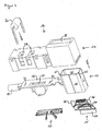
- FIG. 1 shows a perspective view of an embodiment of a solar panel 1 with a plate-shaped solar module 2, wherein at least one voltage-generating solar cell is disposed on an irradiation side of the solar module 2, the electrical lines 9 in the form of conductor strips on the side opposite the irradiation side or opposite terminal side of the solar module 2 led out.
- the electrical lines 9 in the form of conductor strips on the side opposite the irradiation side or opposite terminal side of the solar module 2 led out.
- a junction box 3 is arranged on or on the connection side of the solar module 2 on or on this.
- the junction box 3 has a housing which comprises a base support 4, a wall 5, an outer terminal portion 6, an opening portion 7 and a lid (not shown).
- the base support 4 is arranged on the solar module 2 side facing the junction box, ie below.
- the solar module side facing away from the junction box is accordingly referred to as "top”.
- the lid is arranged to close the junction box.
- the basic carrier 4 Preferably, the attachment of the junction box 3 on the connection side of the solar module 2.
- the base support 4 has an opening portion 7 for carrying out the electrical leads 9 of the solar module 2.
- each of the electric wires 9 is guided through an opening direction 7 through the base support along an insertion direction E, from bottom to top, with each opening portion 7 tapering from bottom to top, advantageously facilitating insertion ,
- each opening portion 7 tapering from bottom to top, advantageously facilitating insertion .
- four opening portions 7 are present and through each opening portion 7, a conductor 9 is guided.
- the wall 5 of the base support 4 extends substantially perpendicular to the base support 4.
- an outer terminal region 6 is arranged, which in this embodiment in each case has a coaxial connector 6a and a coaxial 6b to the solar panel 1 with an external Electrically connect device.
- the wall 5 includes two openings that allow the coaxial plug 6a and the coaxial socket 6b to be in electrical contact with a contactor 10 inside the junction box, respectively.
- the wall 5 preferably at its upper edge at least partially a groove 19, in which preferably a seal can be arranged so that the junction box 3 through the lid, in particular fluid-tight, particularly preferably waterproof, can be closed.
- the openings in the outer connection area can be closed in a fluid-tight manner.
- FIG. 2 shows a view according to FIG. 1 but with a tool 30 shown.
- the aid has not yet been brought into engagement with the contact devices 10.
- FIG. 2 the opening direction O, along which the aid 30 can be zubewgt to the junction box to a force of time the force direction K to the corresponding Terminal contact springs (shown in FIG. 4 ).
- the insertion direction E is shown, along which the conductors 9 can be inserted into the opening regions 7.
- FIG. 3 shows a perspective view of the interior of the junction box 3, comprising the four contact devices 10.
- Each contact device 10 comprises an electrically insulating contact element housing 14 and an electrically conductive contact element 11, which in turn comprises a short-circuit region 12 and a terminal portion 13 which electrically connected to each other through the electrically conductive body of the contact element 11 are connected.
- Arranged on the connection area 13 are the electrical lines 9 (not shown) of the solar module 2 in the mounted state.
- the connection area 13 is arranged completely inside the junction box 3.
- the terminal regions 13 of two adjacent contact devices 10 are electrically connected to one another via the connected solar cell group.
- the short-circuit portions 12 of two adjacent contactors 10 are electrically connected to each other by bypass diodes 20 so that the reverse direction of the bypass diodes 20 are respectively connected in anti-parallel to the current direction of the current flowing across the solar cell group between the adjacent contactors 10. If, for example, due to shadowing, the electrical connection which runs through the solar cell group has a resistance so that the voltage drop exceeds a predeterminable threshold value, the voltage drop between the terminal regions of the corresponding adjacent contact devices 10 also exceeds a threshold value dependent thereon.
- the corresponding bypass diode loses its blocking effect and establishes a short circuit between the adjacent contact devices 10.
- the total current of the solar panel thereby does not flow through the bridged solar cell group, whereby there occur neither electrical power losses due to the increased resistance of the solar cell group nor damage to the solar cell group, for example due to heating due to the electrical power loss. Rather, the electrical current flows through the short-circuit regions 12.
- FIG. 4 shows an exploded perspective view of the embodiment of the contact device 10 of the junction box 3.
- the contact element 11 is preferably made in one piece from metal and comprises, in addition to the short-circuit region 12 and the connection region 13, a female region 18. These regions are electrically connected to one another by the metallic body of the contact element 11.
- the short-circuit region 12 of the contact element 11 is formed in this embodiment as a substantially rectangular opening 21 in the contact element 11, wherein the short-circuit region 12 in a Kurzschlußtitlewiderlager Scheme 23 on both short sides of the opening 21 down along a Diodenein slaughter diode 20 and extends substantially perpendicular to the surface of the opening 21.
- at least two Kurzschlußtitlefederagen 22 are formed in the short-circuit region 12 and spaced from the opening 21, in which the short-circuit contact spring 17 can engage at least partially.
- the diode insertion direction D may, for example, be substantially perpendicular to the main body 4.
- the diode insertion direction D may in particular be parallel to the direction of force K.
- the short-circuit contact spring 17 is preferably made in one piece and contacted in a rest position of the short-circuit contact spring 17 at least partially the Kurzschluß.widerlager Symposium 23.
- the short-circuit contact spring 17 changes to an actuation position, so that the Kurzschlußtitlefeder 17 partially not contacted the Kurzschluß.widerlager Symposium 23.
- the terminal region of the bypass diode 20 is disposed between the short-circuit contact spring 17 and Kurzschlußtitlewiderlager Surrey Scotland 23 and clamped there by a restoring force of the short-circuit contact spring 17, in particular releasably fixed.
- connection region 13 of the contact element 11 is in this embodiment substantially as a hollow profile, in particular with a substantially rectangular cross-section at a horizontal sectional plane and / or substantially rectangular cross-section at substantially vertical Cutting plane formed.
- an at least partially substantially flat Anschluß.widerlager Society 24 is arranged as a preferred connection element 24 such that it extends along an insertion direction E.
- the substantially flat Anschluß gleichwiderlager Scheme 24 is formed such that it contacts a along the insertion direction E extending conductor strip 9 (not shown).
- the connection region 13 preferably has two slots 25 into which the connection contact spring 15 can engage, at least in some areas.
- the Anschlußtitlewiderlager Scheme 24 and the terminal contact spring 15 are formed such that when arranged in the lead-in 16 conductor 9 in actuation position, but without applied force, due to the spring force of the terminal contact spring 15 of the electrical conductor to the Anschluß.widerlager Society 24 and / or the terminal contact spring 15 electrically connected is.
- the electrical conductor 9 is fixed between the terminal contact spring 9 and the terminal contact abutment region 24, in particular clamped.
- the fixation can be solvable, ie by inserting the aid and applying the force in the direction of force K, the terminal contact spring 15 can be displaced so far that the electrical conductor 9 can be removed from the insertion region 16 again.
- the junction box is thus reusable.
- the terminal contact spring 15 may also be designed so that by applying a correspondingly large force to the junction box 3 against the direction of force K and / or the solar module 2 in the direction of force K, the junction box 3 of the solar module 2 is removable and the connection between the conductor 9 and the contact device 10 is detachable.
- the terminal contact spring 15 has a mounting area 26, a terminal contact 27 and a leaf spring area 28.
- the attachment portion 26 is designed to engage at least partially in the slots 25 and to secure or fix the terminal contact spring 15 to the terminal portion 13 of the contact element 11.
- the terminal contact 27 is executed at least partially flat to at least partially contact the Anschlußtitlewiderlager Society 24, in particular a form-fitting, in a rest position of the terminal contact spring 15.
- the substantially the body of the terminal contact spring 15 forming leaf spring area 28 is preferably formed substantially as a leaf spring. Furthermore, a region of the leaf spring region 28 which is proximal to the attachment region 26 is preferably curved.
- the curvature is formed such that the terminal contact 27 disposed at a distal end of the leaf spring portion 28 contacts a terminal contact abutment portion 24, the terminal contact abutment portion 24 being below and facing the attachment portion 26 and the slots 25, respectively, opposite to the insertion direction E.
- This arrangement results in that a force acting on the leaf spring region 28 of the terminal contact spring 15 from above, ie counter to the insertion direction E (and thus counter to the direction of force K), decontacts the distal end of the terminal contact spring 15 from the terminal region 13 of the contact element 11 causes. In other words, the terminal contact 27 is removed from the terminal contact abutment area 24.
- a force acting on the leaf spring area 28 of the terminal contact spring 15 from below, ie in the insertion direction E causes a pressing or securing of the electrical contact.
- the female portion 18 of the contact element 11 is designed in this embodiment as a substantially cylindrical region.
- the contact element housing 14 is preferably made of electrically insulating material, for example a polymer or rubber.
- the contact element housing 14 has at least one connection opening 28, which is arranged such that the connection region of the bypass diode 20 can be inserted through the connection opening 28 in the short-circuit region 12.
- this connection opening 28 is conical, ie tapers along the diode insertion direction D of the bypass diode 20.
- the contact element housing 14 has a connection area opening 29, which is arranged substantially above the connection area 13 and through which, for example by means of an auxiliary means 30 (shown in FIG FIG. 2 ), a force on the leaf spring portion 28 of the terminal contact spring 15 is transferable.
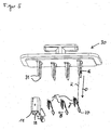
- FIG. 5 shows a perspective view of the auxiliary means 30 or opening tool 30 or opening aid 30 as a preferred aid and the associated arrangement of the terminal contact springs 15, as shown in the Junction box are arranged. Since the opening aid 30 is not yet inserted into the contact elements 11, the terminal contact springs 15 are in the rest position, ie the terminal contact 27 of the terminal contact springs 15 contacts the terminal contact abutment area 24 of the terminal area 13 of the contact element 11.
- the opening aid 30 preferably comprises, for each opening contact spring 15 to be opened, a pair of opening fingers 31, which are preferably conical in the opening direction O.
- the opening direction O equal to the direction of force K.
- each terminal contact spring 15 each have an opening finger.
- the opening fingers 31 of a pair are preferably spaced from each other.
- the opening aid 30 can be inserted along the opening direction O into the contact elements.
- the auxiliary means 30 by the introduction of the auxiliary means 30 along the opening direction O, a force in the direction of force K is applied to the terminal contact spring 15.
- the terminal contact 27 of the terminal contact spring 15 is spaced from the terminal contact abutment area 24.
- the insertion area 16 is at least partially disposed above the opening portion 7 of the base support 4 so that the electrical conductor 9 passed through the opening portion 7 substantially without applying a Insertion force in the insertion region 16 can be arranged.
- FIG. 5 the insertion region 16 is shown with respect to the opening fingers 31, FIG. 5 However, is an exploded view, so that the insertion region 16 is positioned by means of the opening fingers 31 within the contact element 11, provided that the opening fingers 31 are arranged in the contact element 11.
- the terminal contact 27 moves against the direction of movement B of the terminal contact spring 15 back in the direction of its rest position. This rest position is not reached substantially because the electrical line. 9 is arranged between the terminal contact 27 and the Anschluß mecanicwiderlager Scheme 24 and clamped by the restoring force of the terminal contact spring 15. In other words, due to the spring force of the terminal contact spring 15, the terminal contact 27 presses the electrical conductor 9 disposed in the lead-in area 16 against the terminal contact abutment area 24 so that electrical contact between the terminal area and the electrical conductor 9 is established.
- the opening auxiliary 30 and in particular the opening fingers 31 are moved along the opening direction O and also along the direction of force K on the terminal contact springs 15 out.
- the opening fingers thus press along the direction of force K on the terminal contact springs 15.
- the terminal contact springs 15 are moved along the direction of movement B.
- a force along the direction of force K is applied to the opening aid 30.
- This force can be applied to the opening means 30 manually and / or by means of a machine.
- the force is transmitted to the terminal contact springs 15.
- the direction of movement B is preferably perpendicular to the direction of force K.
- the direction of movement B and the direction of force K may also have other angles to one another, preferably between about 70 ° and about 110 °, more preferably between about 80 ° and about 100 °.
- FIG. 6 shows a sectional view through four contact devices 10, each with a contact element 11 and a terminal contact spring 15 and a connecting element 24.
- the terminal contact springs are in a rest position.
Landscapes
- Photovoltaic Devices (AREA)
Claims (13)
- Boîte de jonction (3) pour une carte de circuit imprimé (2), notamment pour un module solaire (2), comprenant :- un support de base (4) avec au moins une région d'ouverture (7) et- au moins un dispositif de contact (10), dans laquelleen cas de force appliquée le long de la direction de force (K), l'au moins un ressort de connecteur (15) est écarté de l'au moins un élément de raccord (24) de telle sorte qu'une région d'introduction (16) entre l'au moins un ressort de connecteur (15) et l'élément de raccord (24) est formée, dans laquelle la région d'introduction (16) est disposée au moins par région au-dessus de l'au moins une région d'ouverture.-- l'au moins un dispositif de contact (10) est disposé à l'intérieur du support de base (4) de telle sorte qu'au moins un conducteur électrique (9) de la carte de circuit imprimé (2) peut être introduit le long d'une direction d'introduction (E) à travers l'au moins une région d'ouverture (7) dans la boîte de jonction (3) et peut être amené en contact avec l'au moins un dispositif de contact (10), dans laquelle la direction d'introduction (E) est essentiellement perpendiculaire au support de base (4) ;-- l'au moins un dispositif de contact (10) comprend au moins un élément de contact (11) avec au moins un ressort de connecteur (15) pouvant être rappelé et au moins un élément de raccord (24), et dans laquelle-- l'au moins un ressort de connecteur (15) peut être déplacé de manière à pouvoir être rappelé par application d'une force parallèle à une direction de force (K) par rapport à l'élément de raccord (24) de telle sorte que l'au moins un conducteur électrique (9) de la carte de circuit imprimé (2) peut être disposé au moins partiellement entre l'au moins un élément de raccord (24) et l'au moins un ressort de connecteur (15), et dans laquelle
- Boîte de jonction (3) selon la revendication 1, dans laquelle le dispositif de contact est conçu de telle sorte que la force peut être appliquée par un moyen sur le ressort de connecteur.
- Boîte de jonction (3) selon une des revendications précédentes, dans laquelle l'au moins un ressort de connecteur (15) est réalisé de manière à pouvoir être rappelé de telle sorte qu'en cas d'absence de la force appliquée, l'au moins un ressort de connecteur (15) fixe le conducteur électrique (9) disposé entre le ressort de connecteur (15) et l'élément de raccord (24) et le connecte de manière électriquement conductrice au dispositif de contact.
- Boîte de jonction (3) selon une des revendications précédentes, dans laquelle une région d'ouverture (7) est associée à chaque dispositif de contact (10) et dans laquelle chaque dispositif de contact (10) entoure la région d'ouverture associée (7).
- Boîte de jonction (3) selon une des revendications précédentes, dans laquelle l'au moins un ressort de connecteur (15) vient en contact avec l'au moins un élément de raccord (24) de manière au moins partiellement mécanique dans une position de repos.
- Boîte de jonction (3) selon une des revendications précédentes, dans laquelle l'au moins un dispositif de contact (10) est disposé par rapport à l'au moins une région d'ouverture de telle sorte que la direction de force (K) et la direction d'introduction sont opposées.
- Boîte de jonction (3) selon une des revendications précédentes, dans laquelle la région d'introduction (16) est réalisée de telle sorte que l'au moins un conducteur électrique (9) peut être introduit essentiellement sans force à travers la région d'ouverture (7) dans la région d'introduction (16).
- Boîte de jonction (3) selon une des revendications précédentes, dans laquelle le ressort de connecteur (15) est un ressort à lames.
- Boîte de jonction (3) selon une des revendications précédentes, dans laquelle le ressort de connecteur (15) présente une région de fixation (26) avec laquelle le ressort de connecteur est fixé au dispositif de contact (10), et le ressort de connecteur présente une région proximale par rapport à la région de fixation (26) et une région distale par rapport à la région de fixation (26), et dans laquelle la région proximale est réalisée de telle sorte qu'en cas d'application d'une force parallèle à la direction de force (K) sur la région proximale, le ressort de connecteur (15) se sépare de l'élément de raccord (24) et en cas d'application d'une force antiparallèle à la direction de force (K) sur la région distale, le ressort de connecteur (15) vient en contact avec l'élément de raccord (24), dans laquelle le ressort de connecteur (15) présente dans la région proximale de préférence une courbure d'environ 10° à environ 170°.
- Panneau solaire (1) comprenant:- au moins un module solaire (2) essentiellement en forme de plaque et- au moins une boîte de jonction (3) selon une des revendications précédentes, dans lequelle module solaire (2) comprend au moins deux conducteurs électriques (9) et les au moins deux conducteurs électriques (9) dépassent chacun à travers une région d'ouverture (7) de la boîte de jonction (3) et sont chacun connectés à un dispositif de contact (10) de la boîte de jonction (3).
- Procédé de connexion automatique d'une boîte de jonction (3) à une carte de circuit imprimé (2), notamment un module solaire (2), avec les étapes :- mise à disposition de la boîte de jonction (3) à l'aide d'un moyen de préhension, dans lequel la boîte de jonction (3) est une boîte de jonction (3) selon une des revendications 1 à 9,- introduction au moins partielle d'un moyen (30) dans l'au moins un dispositif de contact (10) de telle sorte qu'un ressort de connecteur (15) est déplacé de manière à pouvoir être rappelé à l'aide du moyen (30) et une région d'introduction (16) est formée dans le dispositif de contact (10),- activation d'un adhésif sur la boîte de jonction (3) et/ou sur la carte de circuit imprimé (2),- disposition de la boîte de jonction (3) sur une face de la carte de circuit imprimé (2) de telle sorte qu'au moins un conducteur électrique (9) est introduit à travers au moins une région d'ouverture (7) de la boîte de jonction (3) au moins partiellement dans la région d'introduction (16) du dispositif de contact (10) et que la boîte de jonction (3) est fixée à la carte de circuit imprimé (2) à l'aide de l'adhésif,- retrait du moyen (30) de sorte que le ressort de connecteur (15) est au moins partiellement remis à sa place et une connexion entre le dispositif de contact (10) et le conducteur électrique (9) est fixée,- retrait du moyen de préhension.
- Procédé selon la revendication 11, dans lequel le conducteur électrique (9) est fixé dans la région d'introduction (16) dans le dispositif de contact électrique (10) à l'aide du ressort de connecteur (15) et est connecté de manière conductrice au dispositif de contact électrique (10), et dans lequel l'au moins un conducteur électrique (9) est de préférence introduit essentiellement sans force dans la région d'introduction (16) du dispositif de contact (10).
- Procédé selon une des revendications 11 ou 12, dans lequel un dispositif de recouvrement (8) est disposé sur la boîte de jonction (3) de telle sorte que la boîte de jonction (3) est essentiellement entièrement fermée.
Applications Claiming Priority (2)
| Application Number | Priority Date | Filing Date | Title |
|---|---|---|---|
| DE102007043178A DE102007043178A1 (de) | 2007-09-11 | 2007-09-11 | Anschlußdose, Solarpaneel, Kontaktvorrichtung und Verfahren |
| PCT/EP2008/007498 WO2009033695A2 (fr) | 2007-09-11 | 2008-09-11 | Boîte de jonction, panneau solaire, dispositif de contact et procédé |
Publications (2)
| Publication Number | Publication Date |
|---|---|
| EP2201609A2 EP2201609A2 (fr) | 2010-06-30 |
| EP2201609B1 true EP2201609B1 (fr) | 2016-11-09 |
Family
ID=40340130
Family Applications (1)
| Application Number | Title | Priority Date | Filing Date |
|---|---|---|---|
| EP08802058.1A Not-in-force EP2201609B1 (fr) | 2007-09-11 | 2008-09-11 | Boîte de jonction, panneau solaire avec une telle boîte de jonction et procédé pour brancher la boîte de jonction avec le panneau solaire |
Country Status (4)
| Country | Link |
|---|---|
| US (1) | US20100218802A1 (fr) |
| EP (1) | EP2201609B1 (fr) |
| DE (1) | DE102007043178A1 (fr) |
| WO (1) | WO2009033695A2 (fr) |
Families Citing this family (23)
| Publication number | Priority date | Publication date | Assignee | Title |
|---|---|---|---|---|
| US7833033B2 (en) * | 2008-04-16 | 2010-11-16 | Molex Incorporated | Solar panel junction box and components thereof |
| DE102008062034B4 (de) * | 2008-12-12 | 2010-08-12 | Tyco Electronics Amp Gmbh | Verbindungsvorrichtung zum Anschluss an ein Solarmodul und Solarmodul mit einer solchen Verbindungsvorrichtung |
| DE102009022570A1 (de) * | 2009-05-25 | 2010-12-02 | Yamaichi Electronics Deutschland Gmbh | Anschlußdose, Solarpaneel und Verfahren |
| DE102009041968A1 (de) | 2009-09-21 | 2011-04-07 | Telegärtner Gerätebau GmbH | Anschlussdosenanordnung für den elektrischen Anschluss eines Solarmoduls |
| CN102035157B (zh) * | 2009-09-25 | 2013-02-27 | 无锡尚德太阳能电力有限公司 | 一种太阳电池组件用接线盒及太阳电池组件 |
| DE102010002565B8 (de) * | 2010-03-04 | 2012-03-22 | Tyco Electronics Amp Gmbh | Anschlussvorrichtung für ein Solarmodul |
| ES2347514B1 (es) * | 2010-03-11 | 2011-08-29 | Siliken Modules, S.L.U. | Caja de conexiones electricas. |
| US9425734B2 (en) | 2010-07-12 | 2016-08-23 | Lumos Lsx, Llc | Junction cover for photovoltaic panel modules |
| CN201830173U (zh) * | 2010-09-01 | 2011-05-11 | 富士康(昆山)电脑接插件有限公司 | 接线盒 |
| US20120067613A1 (en) * | 2010-09-17 | 2012-03-22 | Delta Electronics, Inc. | Junction box and conductor strip connection device thereof |
| US9083121B2 (en) * | 2010-12-17 | 2015-07-14 | Sunpower Corporation | Diode-included connector, photovoltaic laminate and photovoltaic assembly using same |
| WO2012083049A1 (fr) | 2010-12-17 | 2012-06-21 | First Solar, Inc | Système de connexion électrique |
| CN102956731A (zh) * | 2011-08-23 | 2013-03-06 | 杜邦太阳能有限公司 | 太阳能接线盒 |
| JP2013084679A (ja) * | 2011-10-06 | 2013-05-09 | Hosiden Corp | 太陽電池モジュール用端子ボックス |
| US8963000B2 (en) * | 2011-10-11 | 2015-02-24 | Hon Hai Precision Industry Co., Ltd. | Junction box having improved clips |
| JP5729648B2 (ja) * | 2011-10-13 | 2015-06-03 | ホシデン株式会社 | 太陽電池モジュール用端子ボックス |
| TWM441053U (en) * | 2012-05-25 | 2012-11-11 | T Conn Prec Corp | Nut stopper structure of solar junction box |
| FR3005233B1 (fr) * | 2013-04-26 | 2015-04-17 | Sagemcom Energy & Telecom Sas | Equipement electrique a raccordement multiple facilite |
| WO2016103626A1 (fr) * | 2014-12-24 | 2016-06-30 | パナソニックIpマネジメント株式会社 | Boîte de bornes et module de batterie solaire sur lequel est fixée ladite boîte de bornes |
| US9780723B2 (en) * | 2015-06-29 | 2017-10-03 | Te Connectivity Corporation | Terminal for solar junction box |
| CN109287133A (zh) * | 2016-01-06 | 2019-01-29 | 莱尼电气线缆(中国)有限公司 | 太阳能接线盒 |
| CN207304475U (zh) * | 2017-10-25 | 2018-05-01 | 江苏英迈能源科技有限公司 | 功能整合型可拆卸式光伏组件接线盒 |
| DE102021125242A1 (de) * | 2021-09-29 | 2023-03-30 | Weidmüller Interface GmbH & Co. KG | Photovoltaikmodul und Anschlussanordnung für ein Photovoltaikmodul |
Citations (2)
| Publication number | Priority date | Publication date | Assignee | Title |
|---|---|---|---|---|
| DE202005018884U1 (de) * | 2005-12-02 | 2006-02-09 | Multi-Holding Ag | Anschlussdose für ein Solarpaneel sowie Solarpaneel mit einer solchen Anschlussdose |
| EP1777720A1 (fr) * | 2005-10-24 | 2007-04-25 | TYCO Electronics Austria GmbH | Élément électrique, notamment support de relais, avec borne élastique et procédé de fabrication |
Family Cites Families (21)
| Publication number | Priority date | Publication date | Assignee | Title |
|---|---|---|---|---|
| US4310211A (en) * | 1979-12-26 | 1982-01-12 | Amp Incorporated | High current contact system for solar modules |
| US4460232A (en) * | 1982-05-24 | 1984-07-17 | Amp, Incorporated | Junction box for solar modules |
| DE9422155U1 (de) * | 1994-10-06 | 1998-08-06 | Siemens Ag | Federkraftklemme |
| DE29910180U1 (de) * | 1999-06-11 | 2000-10-19 | Weidmueller Interface | Betätigungswerkzeug |
| ATE397306T1 (de) * | 1999-11-17 | 2008-06-15 | Tyco Electronics Amp Gmbh | Vorrichtung zur verbindung von leiterfolien, insbesondere von einem solarmodul |
| JP3744458B2 (ja) * | 2002-04-10 | 2006-02-08 | 住友電装株式会社 | 太陽電池モジュール用端子ボックス装置 |
| DE20311183U1 (de) * | 2003-07-21 | 2004-07-08 | Tyco Electronics Amp Gmbh | Anschlussdose für ein Solarpaneel und Solarpaneel |
| DE20311184U1 (de) * | 2003-07-21 | 2004-02-19 | Tyco Electronics Amp Gmbh | Anschlussdose zum Anschließen an ein Solarpaneel |
| JP2005310888A (ja) * | 2004-04-19 | 2005-11-04 | Sumitomo Wiring Syst Ltd | 太陽電池モジュール用端子ボックス及び整流素子ユニット |
| DE102004020958B3 (de) * | 2004-04-28 | 2005-08-25 | Rose Systemtechnik Gmbh | Anschlußklemme und damit gebildete Anschlußbox |
| JP3744531B1 (ja) * | 2004-05-07 | 2006-02-15 | 住友電装株式会社 | 太陽電池モジュール用端子ボックス及び整流素子ユニット |
| DE102004025627A1 (de) * | 2004-05-25 | 2005-12-22 | Tyco Electronics Amp Gmbh | Solarmodul mit Anschlusselement |
| DE202005008385U1 (de) | 2005-05-25 | 2005-10-20 | G. Spelsberg Gmbh + Co. Kg | Elektrische Anschluß- und Verbindungsdose |
| DE102005024644A1 (de) * | 2005-05-25 | 2006-11-30 | G. Spelsberg Gmbh & Co. Kg | Elektrische Anschluß- und Verbindungsdose |
| DE102005025976B4 (de) * | 2005-06-03 | 2007-03-15 | Günther Spelsberg GmbH & Co. KG | Elektrische Anschluß- und Verbindungsdose für ein Solarzellenmodul |
| DE102005025632B4 (de) * | 2005-06-03 | 2015-09-17 | Te Connectivity Germany Gmbh | Verbindungsvorrichtung für den Anschluss elektrischer Folienleiter |
| US7291036B1 (en) * | 2006-11-08 | 2007-11-06 | Tyco Electronics Corporation | Photovoltaic connection system |
| DE102006056259A1 (de) * | 2006-11-27 | 2008-05-29 | Kostal Industrie Elektrik Gmbh | Elektrische Leiterplatte mit einer Anschlussklemme |
| DE102008010026A1 (de) * | 2008-02-20 | 2009-08-27 | Kostal Industrie Elektrik Gmbh | Elektrische Anschluss- und Verbindungsdose für ein Solarzellenmodul |
| DE102008022049B4 (de) * | 2008-05-03 | 2010-07-15 | Lumberg Connect Gmbh | Anschlussdose zur Anbindung eines Solarmoduls |
| DE102008022051A1 (de) * | 2008-05-03 | 2009-11-19 | Lumberg Connect Gmbh | Anschlussdose für ein Solarmodul |
-
2007
- 2007-09-11 DE DE102007043178A patent/DE102007043178A1/de not_active Withdrawn
-
2008
- 2008-09-11 EP EP08802058.1A patent/EP2201609B1/fr not_active Not-in-force
- 2008-09-11 WO PCT/EP2008/007498 patent/WO2009033695A2/fr active Application Filing
-
2010
- 2010-03-10 US US12/721,073 patent/US20100218802A1/en not_active Abandoned
Patent Citations (2)
| Publication number | Priority date | Publication date | Assignee | Title |
|---|---|---|---|---|
| EP1777720A1 (fr) * | 2005-10-24 | 2007-04-25 | TYCO Electronics Austria GmbH | Élément électrique, notamment support de relais, avec borne élastique et procédé de fabrication |
| DE202005018884U1 (de) * | 2005-12-02 | 2006-02-09 | Multi-Holding Ag | Anschlussdose für ein Solarpaneel sowie Solarpaneel mit einer solchen Anschlussdose |
Also Published As
| Publication number | Publication date |
|---|---|
| WO2009033695A3 (fr) | 2009-06-11 |
| DE102007043178A1 (de) | 2009-03-12 |
| US20100218802A1 (en) | 2010-09-02 |
| WO2009033695A2 (fr) | 2009-03-19 |
| EP2201609A2 (fr) | 2010-06-30 |
Similar Documents
| Publication | Publication Date | Title |
|---|---|---|
| EP2201609B1 (fr) | Boîte de jonction, panneau solaire avec une telle boîte de jonction et procédé pour brancher la boîte de jonction avec le panneau solaire | |
| EP2232582B1 (fr) | Boite de jonction, utilisation, panneau solaire, element de contact et procede | |
| DE102007051134B4 (de) | Anschluss- und Verbindungsdose für ein Solarmodul | |
| EP2118977B1 (fr) | Boîtier de raccordement et de connexion pour un module solaire | |
| DE102009033481B4 (de) | Anschluss- und Verbindungsvorrichtung | |
| EP2232966B1 (fr) | Boîte de jonction, système, procédé et utilisation | |
| DE102007037130B3 (de) | Anschluss- und Verbindungsdose für ein Solarmodul | |
| DE102007031351B4 (de) | Verbindungsvorrichtung zur Verbindung eines ersten elektrischen Leiters mit einem elektrischen Leiter eines photovoltaischen Solarmoduls | |
| DE102007006433A1 (de) | Anschlußbox für den elektrischen Anschluß eines Solarmoduls und Verfahren zur Montage einer Anschlußbox auf einem Solarmodul | |
| DE202009012176U1 (de) | Anschlußdose und Solarpaneel | |
| EP2509116B1 (fr) | Dispositif de positionnement, agencement de raccordement et procédé de contrôle | |
| EP2296181B1 (fr) | Boîte de jonction, son utilisation dans un panneau solaire et procédé de fabrication | |
| EP2436038B1 (fr) | Panneau solaire, procédé de fabrication de ce panneau et boîte de pontage | |
| EP2256825B1 (fr) | Boîtier de connexion ou intermédiaire avec dépot de soudure | |
| DE60119830T2 (de) | Rahmenschenkel für ein Rahmengestell, als Leiter zur Verteilung elektrischer Energie | |
| DE102012219778A1 (de) | Batteriemodulanschluss bildende Stromschiene | |
| EP2386125B1 (fr) | Panneau solaire et procédé pour sa fabrication | |
| DE102008057327B3 (de) | Solarpaneel, Verfahren zum Herstellen und Überbrückungsdose | |
| DE102013001873B4 (de) | Batteriemodul, Batterie und Verfahren zum elektrischen Kontaktieren eines Batteriemoduls | |
| DE102020112710A1 (de) | Isolierkörper für Schraub- und Crimpkontakte |
Legal Events
| Date | Code | Title | Description |
|---|---|---|---|
| PUAI | Public reference made under article 153(3) epc to a published international application that has entered the european phase |
Free format text: ORIGINAL CODE: 0009012 |
|
| 17P | Request for examination filed |
Effective date: 20100409 |
|
| AK | Designated contracting states |
Kind code of ref document: A2 Designated state(s): AT BE BG CH CY CZ DE DK EE ES FI FR GB GR HR HU IE IS IT LI LT LU LV MC MT NL NO PL PT RO SE SI SK TR |
|
| AX | Request for extension of the european patent |
Extension state: AL BA MK RS |
|
| DAX | Request for extension of the european patent (deleted) | ||
| RAP1 | Party data changed (applicant data changed or rights of an application transferred) |
Owner name: YAMAICHI ELECTRONICS DEUTSCHLAND GMBH Owner name: YAMAICHI ELECTRONICS CO., LTD. |
|
| 17Q | First examination report despatched |
Effective date: 20131202 |
|
| REG | Reference to a national code |
Ref country code: DE Ref legal event code: R079 Ref document number: 502008014784 Country of ref document: DE Free format text: PREVIOUS MAIN CLASS: H01L0031048000 Ipc: H02S0040340000 |
|
| RIC1 | Information provided on ipc code assigned before grant |
Ipc: H02S 40/34 20140101AFI20160211BHEP |
|
| GRAP | Despatch of communication of intention to grant a patent |
Free format text: ORIGINAL CODE: EPIDOSNIGR1 |
|
| RIC1 | Information provided on ipc code assigned before grant |
Ipc: H01R 4/48 20060101ALI20160304BHEP Ipc: H02S 40/34 20140101AFI20160304BHEP |
|
| INTG | Intention to grant announced |
Effective date: 20160411 |
|
| GRAS | Grant fee paid |
Free format text: ORIGINAL CODE: EPIDOSNIGR3 |
|
| GRAA | (expected) grant |
Free format text: ORIGINAL CODE: 0009210 |
|
| AK | Designated contracting states |
Kind code of ref document: B1 Designated state(s): AT BE BG CH CY CZ DE DK EE ES FI FR GB GR HR HU IE IS IT LI LT LU LV MC MT NL NO PL PT RO SE SI SK TR |
|
| REG | Reference to a national code |
Ref country code: GB Ref legal event code: FG4D Free format text: NOT ENGLISH |
|
| REG | Reference to a national code |
Ref country code: AT Ref legal event code: REF Ref document number: 844736 Country of ref document: AT Kind code of ref document: T Effective date: 20161115 Ref country code: CH Ref legal event code: EP |
|
| REG | Reference to a national code |
Ref country code: IE Ref legal event code: FG4D Free format text: LANGUAGE OF EP DOCUMENT: GERMAN |
|
| REG | Reference to a national code |
Ref country code: DE Ref legal event code: R096 Ref document number: 502008014784 Country of ref document: DE |
|
| PG25 | Lapsed in a contracting state [announced via postgrant information from national office to epo] |
Ref country code: LV Free format text: LAPSE BECAUSE OF FAILURE TO SUBMIT A TRANSLATION OF THE DESCRIPTION OR TO PAY THE FEE WITHIN THE PRESCRIBED TIME-LIMIT Effective date: 20161109 |
|
| REG | Reference to a national code |
Ref country code: LT Ref legal event code: MG4D |
|
| REG | Reference to a national code |
Ref country code: NL Ref legal event code: MP Effective date: 20161109 |
|
| PG25 | Lapsed in a contracting state [announced via postgrant information from national office to epo] |
Ref country code: SE Free format text: LAPSE BECAUSE OF FAILURE TO SUBMIT A TRANSLATION OF THE DESCRIPTION OR TO PAY THE FEE WITHIN THE PRESCRIBED TIME-LIMIT Effective date: 20161109 Ref country code: NL Free format text: LAPSE BECAUSE OF FAILURE TO SUBMIT A TRANSLATION OF THE DESCRIPTION OR TO PAY THE FEE WITHIN THE PRESCRIBED TIME-LIMIT Effective date: 20161109 Ref country code: GR Free format text: LAPSE BECAUSE OF FAILURE TO SUBMIT A TRANSLATION OF THE DESCRIPTION OR TO PAY THE FEE WITHIN THE PRESCRIBED TIME-LIMIT Effective date: 20170210 Ref country code: NO Free format text: LAPSE BECAUSE OF FAILURE TO SUBMIT A TRANSLATION OF THE DESCRIPTION OR TO PAY THE FEE WITHIN THE PRESCRIBED TIME-LIMIT Effective date: 20170209 Ref country code: LT Free format text: LAPSE BECAUSE OF FAILURE TO SUBMIT A TRANSLATION OF THE DESCRIPTION OR TO PAY THE FEE WITHIN THE PRESCRIBED TIME-LIMIT Effective date: 20161109 |
|
| PG25 | Lapsed in a contracting state [announced via postgrant information from national office to epo] |
Ref country code: FI Free format text: LAPSE BECAUSE OF FAILURE TO SUBMIT A TRANSLATION OF THE DESCRIPTION OR TO PAY THE FEE WITHIN THE PRESCRIBED TIME-LIMIT Effective date: 20161109 Ref country code: PL Free format text: LAPSE BECAUSE OF FAILURE TO SUBMIT A TRANSLATION OF THE DESCRIPTION OR TO PAY THE FEE WITHIN THE PRESCRIBED TIME-LIMIT Effective date: 20161109 Ref country code: ES Free format text: LAPSE BECAUSE OF FAILURE TO SUBMIT A TRANSLATION OF THE DESCRIPTION OR TO PAY THE FEE WITHIN THE PRESCRIBED TIME-LIMIT Effective date: 20161109 Ref country code: IS Free format text: LAPSE BECAUSE OF FAILURE TO SUBMIT A TRANSLATION OF THE DESCRIPTION OR TO PAY THE FEE WITHIN THE PRESCRIBED TIME-LIMIT Effective date: 20170309 Ref country code: HR Free format text: LAPSE BECAUSE OF FAILURE TO SUBMIT A TRANSLATION OF THE DESCRIPTION OR TO PAY THE FEE WITHIN THE PRESCRIBED TIME-LIMIT Effective date: 20161109 Ref country code: PT Free format text: LAPSE BECAUSE OF FAILURE TO SUBMIT A TRANSLATION OF THE DESCRIPTION OR TO PAY THE FEE WITHIN THE PRESCRIBED TIME-LIMIT Effective date: 20170309 |
|
| PG25 | Lapsed in a contracting state [announced via postgrant information from national office to epo] |
Ref country code: EE Free format text: LAPSE BECAUSE OF FAILURE TO SUBMIT A TRANSLATION OF THE DESCRIPTION OR TO PAY THE FEE WITHIN THE PRESCRIBED TIME-LIMIT Effective date: 20161109 Ref country code: DK Free format text: LAPSE BECAUSE OF FAILURE TO SUBMIT A TRANSLATION OF THE DESCRIPTION OR TO PAY THE FEE WITHIN THE PRESCRIBED TIME-LIMIT Effective date: 20161109 Ref country code: CZ Free format text: LAPSE BECAUSE OF FAILURE TO SUBMIT A TRANSLATION OF THE DESCRIPTION OR TO PAY THE FEE WITHIN THE PRESCRIBED TIME-LIMIT Effective date: 20161109 Ref country code: SK Free format text: LAPSE BECAUSE OF FAILURE TO SUBMIT A TRANSLATION OF THE DESCRIPTION OR TO PAY THE FEE WITHIN THE PRESCRIBED TIME-LIMIT Effective date: 20161109 Ref country code: RO Free format text: LAPSE BECAUSE OF FAILURE TO SUBMIT A TRANSLATION OF THE DESCRIPTION OR TO PAY THE FEE WITHIN THE PRESCRIBED TIME-LIMIT Effective date: 20161109 |
|
| REG | Reference to a national code |
Ref country code: DE Ref legal event code: R097 Ref document number: 502008014784 Country of ref document: DE |
|
| REG | Reference to a national code |
Ref country code: FR Ref legal event code: PLFP Year of fee payment: 10 |
|
| PG25 | Lapsed in a contracting state [announced via postgrant information from national office to epo] |
Ref country code: IT Free format text: LAPSE BECAUSE OF FAILURE TO SUBMIT A TRANSLATION OF THE DESCRIPTION OR TO PAY THE FEE WITHIN THE PRESCRIBED TIME-LIMIT Effective date: 20161109 Ref country code: BG Free format text: LAPSE BECAUSE OF FAILURE TO SUBMIT A TRANSLATION OF THE DESCRIPTION OR TO PAY THE FEE WITHIN THE PRESCRIBED TIME-LIMIT Effective date: 20170209 |
|
| PLBE | No opposition filed within time limit |
Free format text: ORIGINAL CODE: 0009261 |
|
| STAA | Information on the status of an ep patent application or granted ep patent |
Free format text: STATUS: NO OPPOSITION FILED WITHIN TIME LIMIT |
|
| 26N | No opposition filed |
Effective date: 20170810 |
|
| PG25 | Lapsed in a contracting state [announced via postgrant information from national office to epo] |
Ref country code: SI Free format text: LAPSE BECAUSE OF FAILURE TO SUBMIT A TRANSLATION OF THE DESCRIPTION OR TO PAY THE FEE WITHIN THE PRESCRIBED TIME-LIMIT Effective date: 20161109 |
|
| REG | Reference to a national code |
Ref country code: CH Ref legal event code: PL |
|
| PG25 | Lapsed in a contracting state [announced via postgrant information from national office to epo] |
Ref country code: MC Free format text: LAPSE BECAUSE OF FAILURE TO SUBMIT A TRANSLATION OF THE DESCRIPTION OR TO PAY THE FEE WITHIN THE PRESCRIBED TIME-LIMIT Effective date: 20161109 |
|
| REG | Reference to a national code |
Ref country code: IE Ref legal event code: MM4A |
|
| REG | Reference to a national code |
Ref country code: BE Ref legal event code: MM Effective date: 20170930 |
|
| PG25 | Lapsed in a contracting state [announced via postgrant information from national office to epo] |
Ref country code: LU Free format text: LAPSE BECAUSE OF NON-PAYMENT OF DUE FEES Effective date: 20170911 |
|
| PG25 | Lapsed in a contracting state [announced via postgrant information from national office to epo] |
Ref country code: IE Free format text: LAPSE BECAUSE OF NON-PAYMENT OF DUE FEES Effective date: 20170911 Ref country code: CH Free format text: LAPSE BECAUSE OF NON-PAYMENT OF DUE FEES Effective date: 20170930 Ref country code: LI Free format text: LAPSE BECAUSE OF NON-PAYMENT OF DUE FEES Effective date: 20170930 |
|
| PG25 | Lapsed in a contracting state [announced via postgrant information from national office to epo] |
Ref country code: BE Free format text: LAPSE BECAUSE OF NON-PAYMENT OF DUE FEES Effective date: 20170930 |
|
| REG | Reference to a national code |
Ref country code: FR Ref legal event code: PLFP Year of fee payment: 11 |
|
| PG25 | Lapsed in a contracting state [announced via postgrant information from national office to epo] |
Ref country code: MT Free format text: LAPSE BECAUSE OF FAILURE TO SUBMIT A TRANSLATION OF THE DESCRIPTION OR TO PAY THE FEE WITHIN THE PRESCRIBED TIME-LIMIT Effective date: 20161109 |
|
| REG | Reference to a national code |
Ref country code: AT Ref legal event code: MM01 Ref document number: 844736 Country of ref document: AT Kind code of ref document: T Effective date: 20170911 |
|
| PG25 | Lapsed in a contracting state [announced via postgrant information from national office to epo] |
Ref country code: AT Free format text: LAPSE BECAUSE OF NON-PAYMENT OF DUE FEES Effective date: 20170911 |
|
| PG25 | Lapsed in a contracting state [announced via postgrant information from national office to epo] |
Ref country code: HU Free format text: LAPSE BECAUSE OF FAILURE TO SUBMIT A TRANSLATION OF THE DESCRIPTION OR TO PAY THE FEE WITHIN THE PRESCRIBED TIME-LIMIT; INVALID AB INITIO Effective date: 20080911 |
|
| PG25 | Lapsed in a contracting state [announced via postgrant information from national office to epo] |
Ref country code: CY Free format text: LAPSE BECAUSE OF NON-PAYMENT OF DUE FEES Effective date: 20161109 |
|
| PG25 | Lapsed in a contracting state [announced via postgrant information from national office to epo] |
Ref country code: TR Free format text: LAPSE BECAUSE OF FAILURE TO SUBMIT A TRANSLATION OF THE DESCRIPTION OR TO PAY THE FEE WITHIN THE PRESCRIBED TIME-LIMIT Effective date: 20161109 |
|
| PGFP | Annual fee paid to national office [announced via postgrant information from national office to epo] |
Ref country code: FR Payment date: 20200928 Year of fee payment: 13 Ref country code: DE Payment date: 20200929 Year of fee payment: 13 Ref country code: GB Payment date: 20200924 Year of fee payment: 13 |
|
| REG | Reference to a national code |
Ref country code: DE Ref legal event code: R119 Ref document number: 502008014784 Country of ref document: DE |
|
| GBPC | Gb: european patent ceased through non-payment of renewal fee |
Effective date: 20210911 |
|
| PG25 | Lapsed in a contracting state [announced via postgrant information from national office to epo] |
Ref country code: GB Free format text: LAPSE BECAUSE OF NON-PAYMENT OF DUE FEES Effective date: 20210911 Ref country code: FR Free format text: LAPSE BECAUSE OF NON-PAYMENT OF DUE FEES Effective date: 20210930 Ref country code: DE Free format text: LAPSE BECAUSE OF NON-PAYMENT OF DUE FEES Effective date: 20220401 |