EP2118977B1 - Anschluss- und verbindungsdose für ein solarmodul - Google Patents
Anschluss- und verbindungsdose für ein solarmodul Download PDFInfo
- Publication number
- EP2118977B1 EP2118977B1 EP08707534A EP08707534A EP2118977B1 EP 2118977 B1 EP2118977 B1 EP 2118977B1 EP 08707534 A EP08707534 A EP 08707534A EP 08707534 A EP08707534 A EP 08707534A EP 2118977 B1 EP2118977 B1 EP 2118977B1
- Authority
- EP
- European Patent Office
- Prior art keywords
- connection
- solar module
- junction box
- housing
- flat conductor
- Prior art date
- Legal status (The legal status is an assumption and is not a legal conclusion. Google has not performed a legal analysis and makes no representation as to the accuracy of the status listed.)
- Not-in-force
Links
Images


Classifications
-
- H—ELECTRICITY
- H01—ELECTRIC ELEMENTS
- H01R—ELECTRICALLY-CONDUCTIVE CONNECTIONS; STRUCTURAL ASSOCIATIONS OF A PLURALITY OF MUTUALLY-INSULATED ELECTRICAL CONNECTING ELEMENTS; COUPLING DEVICES; CURRENT COLLECTORS
- H01R12/00—Structural associations of a plurality of mutually-insulated electrical connecting elements, specially adapted for printed circuits, e.g. printed circuit boards [PCB], flat or ribbon cables, or like generally planar structures, e.g. terminal strips, terminal blocks; Coupling devices specially adapted for printed circuits, flat or ribbon cables, or like generally planar structures; Terminals specially adapted for contact with, or insertion into, printed circuits, flat or ribbon cables, or like generally planar structures
- H01R12/50—Fixed connections
- H01R12/59—Fixed connections for flexible printed circuits, flat or ribbon cables or like structures
- H01R12/592—Fixed connections for flexible printed circuits, flat or ribbon cables or like structures connections to contact elements
-
- H—ELECTRICITY
- H01—ELECTRIC ELEMENTS
- H01R—ELECTRICALLY-CONDUCTIVE CONNECTIONS; STRUCTURAL ASSOCIATIONS OF A PLURALITY OF MUTUALLY-INSULATED ELECTRICAL CONNECTING ELEMENTS; COUPLING DEVICES; CURRENT COLLECTORS
- H01R4/00—Electrically-conductive connections between two or more conductive members in direct contact, i.e. touching one another; Means for effecting or maintaining such contact; Electrically-conductive connections having two or more spaced connecting locations for conductors and using contact members penetrating insulation
- H01R4/28—Clamped connections, spring connections
- H01R4/48—Clamped connections, spring connections utilising a spring, clip, or other resilient member
- H01R4/4809—Clamped connections, spring connections utilising a spring, clip, or other resilient member using a leaf spring to bias the conductor toward the busbar
- H01R4/484—Spring housing details
-
- H—ELECTRICITY
- H01—ELECTRIC ELEMENTS
- H01R—ELECTRICALLY-CONDUCTIVE CONNECTIONS; STRUCTURAL ASSOCIATIONS OF A PLURALITY OF MUTUALLY-INSULATED ELECTRICAL CONNECTING ELEMENTS; COUPLING DEVICES; CURRENT COLLECTORS
- H01R4/00—Electrically-conductive connections between two or more conductive members in direct contact, i.e. touching one another; Means for effecting or maintaining such contact; Electrically-conductive connections having two or more spaced connecting locations for conductors and using contact members penetrating insulation
- H01R4/28—Clamped connections, spring connections
- H01R4/48—Clamped connections, spring connections utilising a spring, clip, or other resilient member
- H01R4/4809—Clamped connections, spring connections utilising a spring, clip, or other resilient member using a leaf spring to bias the conductor toward the busbar
- H01R4/4846—Busbar details
- H01R4/485—Single busbar common to multiple springs
-
- H—ELECTRICITY
- H01—ELECTRIC ELEMENTS
- H01R—ELECTRICALLY-CONDUCTIVE CONNECTIONS; STRUCTURAL ASSOCIATIONS OF A PLURALITY OF MUTUALLY-INSULATED ELECTRICAL CONNECTING ELEMENTS; COUPLING DEVICES; CURRENT COLLECTORS
- H01R4/00—Electrically-conductive connections between two or more conductive members in direct contact, i.e. touching one another; Means for effecting or maintaining such contact; Electrically-conductive connections having two or more spaced connecting locations for conductors and using contact members penetrating insulation
- H01R4/28—Clamped connections, spring connections
- H01R4/48—Clamped connections, spring connections utilising a spring, clip, or other resilient member
- H01R4/489—Clamped connections, spring connections utilising a spring, clip, or other resilient member spring force increased by screw, cam, wedge, or other fastening means
-
- H—ELECTRICITY
- H01—ELECTRIC ELEMENTS
- H01R—ELECTRICALLY-CONDUCTIVE CONNECTIONS; STRUCTURAL ASSOCIATIONS OF A PLURALITY OF MUTUALLY-INSULATED ELECTRICAL CONNECTING ELEMENTS; COUPLING DEVICES; CURRENT COLLECTORS
- H01R9/00—Structural associations of a plurality of mutually-insulated electrical connecting elements, e.g. terminal strips or terminal blocks; Terminals or binding posts mounted upon a base or in a case; Bases therefor
- H01R9/22—Bases, e.g. strip, block, panel
- H01R9/24—Terminal blocks
- H01R9/2416—Means for guiding or retaining wires or cables connected to terminal blocks
-
- H—ELECTRICITY
- H02—GENERATION; CONVERSION OR DISTRIBUTION OF ELECTRIC POWER
- H02G—INSTALLATION OF ELECTRIC CABLES OR LINES, OR OF COMBINED OPTICAL AND ELECTRIC CABLES OR LINES
- H02G3/00—Installations of electric cables or lines or protective tubing therefor in or on buildings, equivalent structures or vehicles
- H02G3/02—Details
- H02G3/08—Distribution boxes; Connection or junction boxes
- H02G3/081—Bases, casings or covers
- H02G3/083—Inlets
-
- H—ELECTRICITY
- H02—GENERATION; CONVERSION OR DISTRIBUTION OF ELECTRIC POWER
- H02G—INSTALLATION OF ELECTRIC CABLES OR LINES, OR OF COMBINED OPTICAL AND ELECTRIC CABLES OR LINES
- H02G3/00—Installations of electric cables or lines or protective tubing therefor in or on buildings, equivalent structures or vehicles
- H02G3/02—Details
- H02G3/08—Distribution boxes; Connection or junction boxes
- H02G3/16—Distribution boxes; Connection or junction boxes structurally associated with support for line-connecting terminals within the box
-
- H—ELECTRICITY
- H02—GENERATION; CONVERSION OR DISTRIBUTION OF ELECTRIC POWER
- H02S—GENERATION OF ELECTRIC POWER BY CONVERSION OF INFRARED RADIATION, VISIBLE LIGHT OR ULTRAVIOLET LIGHT, e.g. USING PHOTOVOLTAIC [PV] MODULES
- H02S40/00—Components or accessories in combination with PV modules, not provided for in groups H02S10/00 - H02S30/00
- H02S40/30—Electrical components
- H02S40/34—Electrical components comprising specially adapted electrical connection means to be structurally associated with the PV module, e.g. junction boxes
-
- H—ELECTRICITY
- H10—SEMICONDUCTOR DEVICES; ELECTRIC SOLID-STATE DEVICES NOT OTHERWISE PROVIDED FOR
- H10F—INORGANIC SEMICONDUCTOR DEVICES SENSITIVE TO INFRARED RADIATION, LIGHT, ELECTROMAGNETIC RADIATION OF SHORTER WAVELENGTH OR CORPUSCULAR RADIATION
- H10F77/00—Constructional details of devices covered by this subclass
- H10F77/93—Interconnections
- H10F77/933—Interconnections for devices having potential barriers
- H10F77/935—Interconnections for devices having potential barriers for photovoltaic devices or modules
- H10F77/939—Output lead wires or elements
-
- H—ELECTRICITY
- H01—ELECTRIC ELEMENTS
- H01R—ELECTRICALLY-CONDUCTIVE CONNECTIONS; STRUCTURAL ASSOCIATIONS OF A PLURALITY OF MUTUALLY-INSULATED ELECTRICAL CONNECTING ELEMENTS; COUPLING DEVICES; CURRENT COLLECTORS
- H01R2103/00—Two poles
-
- H—ELECTRICITY
- H01—ELECTRIC ELEMENTS
- H01R—ELECTRICALLY-CONDUCTIVE CONNECTIONS; STRUCTURAL ASSOCIATIONS OF A PLURALITY OF MUTUALLY-INSULATED ELECTRICAL CONNECTING ELEMENTS; COUPLING DEVICES; CURRENT COLLECTORS
- H01R24/00—Two-part coupling devices, or either of their cooperating parts, characterised by their overall structure
- H01R24/58—Contacts spaced along longitudinal axis of engagement
-
- H—ELECTRICITY
- H01—ELECTRIC ELEMENTS
- H01R—ELECTRICALLY-CONDUCTIVE CONNECTIONS; STRUCTURAL ASSOCIATIONS OF A PLURALITY OF MUTUALLY-INSULATED ELECTRICAL CONNECTING ELEMENTS; COUPLING DEVICES; CURRENT COLLECTORS
- H01R4/00—Electrically-conductive connections between two or more conductive members in direct contact, i.e. touching one another; Means for effecting or maintaining such contact; Electrically-conductive connections having two or more spaced connecting locations for conductors and using contact members penetrating insulation
- H01R4/28—Clamped connections, spring connections
- H01R4/48—Clamped connections, spring connections utilising a spring, clip, or other resilient member
- H01R4/4809—Clamped connections, spring connections utilising a spring, clip, or other resilient member using a leaf spring to bias the conductor toward the busbar
- H01R4/48185—Clamped connections, spring connections utilising a spring, clip, or other resilient member using a leaf spring to bias the conductor toward the busbar adapted for axial insertion of a wire end
- H01R4/4819—Clamped connections, spring connections utilising a spring, clip, or other resilient member using a leaf spring to bias the conductor toward the busbar adapted for axial insertion of a wire end the spring shape allowing insertion of the conductor end when the spring is unbiased
- H01R4/4821—Single-blade spring
-
- H—ELECTRICITY
- H01—ELECTRIC ELEMENTS
- H01R—ELECTRICALLY-CONDUCTIVE CONNECTIONS; STRUCTURAL ASSOCIATIONS OF A PLURALITY OF MUTUALLY-INSULATED ELECTRICAL CONNECTING ELEMENTS; COUPLING DEVICES; CURRENT COLLECTORS
- H01R4/00—Electrically-conductive connections between two or more conductive members in direct contact, i.e. touching one another; Means for effecting or maintaining such contact; Electrically-conductive connections having two or more spaced connecting locations for conductors and using contact members penetrating insulation
- H01R4/28—Clamped connections, spring connections
- H01R4/48—Clamped connections, spring connections utilising a spring, clip, or other resilient member
- H01R4/4809—Clamped connections, spring connections utilising a spring, clip, or other resilient member using a leaf spring to bias the conductor toward the busbar
- H01R4/4828—Spring-activating arrangements mounted on or integrally formed with the spring housing
- H01R4/483—Pivoting arrangements, e.g. lever pushing on the spring
-
- H—ELECTRICITY
- H01—ELECTRIC ELEMENTS
- H01R—ELECTRICALLY-CONDUCTIVE CONNECTIONS; STRUCTURAL ASSOCIATIONS OF A PLURALITY OF MUTUALLY-INSULATED ELECTRICAL CONNECTING ELEMENTS; COUPLING DEVICES; CURRENT COLLECTORS
- H01R4/00—Electrically-conductive connections between two or more conductive members in direct contact, i.e. touching one another; Means for effecting or maintaining such contact; Electrically-conductive connections having two or more spaced connecting locations for conductors and using contact members penetrating insulation
- H01R4/28—Clamped connections, spring connections
- H01R4/48—Clamped connections, spring connections utilising a spring, clip, or other resilient member
- H01R4/4809—Clamped connections, spring connections utilising a spring, clip, or other resilient member using a leaf spring to bias the conductor toward the busbar
- H01R4/4828—Spring-activating arrangements mounted on or integrally formed with the spring housing
- H01R4/4833—Sliding arrangements, e.g. sliding button
-
- Y—GENERAL TAGGING OF NEW TECHNOLOGICAL DEVELOPMENTS; GENERAL TAGGING OF CROSS-SECTIONAL TECHNOLOGIES SPANNING OVER SEVERAL SECTIONS OF THE IPC; TECHNICAL SUBJECTS COVERED BY FORMER USPC CROSS-REFERENCE ART COLLECTIONS [XRACs] AND DIGESTS
- Y02—TECHNOLOGIES OR APPLICATIONS FOR MITIGATION OR ADAPTATION AGAINST CLIMATE CHANGE
- Y02E—REDUCTION OF GREENHOUSE GAS [GHG] EMISSIONS, RELATED TO ENERGY GENERATION, TRANSMISSION OR DISTRIBUTION
- Y02E10/00—Energy generation through renewable energy sources
- Y02E10/50—Photovoltaic [PV] energy
-
- Y—GENERAL TAGGING OF NEW TECHNOLOGICAL DEVELOPMENTS; GENERAL TAGGING OF CROSS-SECTIONAL TECHNOLOGIES SPANNING OVER SEVERAL SECTIONS OF THE IPC; TECHNICAL SUBJECTS COVERED BY FORMER USPC CROSS-REFERENCE ART COLLECTIONS [XRACs] AND DIGESTS
- Y10—TECHNICAL SUBJECTS COVERED BY FORMER USPC
- Y10T—TECHNICAL SUBJECTS COVERED BY FORMER US CLASSIFICATION
- Y10T29/00—Metal working
- Y10T29/49—Method of mechanical manufacture
- Y10T29/49002—Electrical device making
- Y10T29/49117—Conductor or circuit manufacturing
Definitions
- the invention relates to a connection and junction box for a photovoltaic solar module with flexible flat conductor strips, which protrude from the surface of the solar module and a method for connecting a connection and junction box to a solar module.
- Solar modules typically consist of a plurality of solar cells based on semiconductors, which are interconnected to form large-area solar panels.
- a typical solar module has on the side facing the sun a glass pane and on the back of a transparent plastic layer in which the solar cells are embedded.
- the back of the solar module is typically with a weather-resistant plastic composite film, z.
- the monocrystalline or polycrystalline solar cells are electrically interconnected by soldering strips.
- the solar module is still installed in a metal profile frame for attachment and stiffening of the composite.
- a solar module is therefore basically a planar structure, similar to a thick glass pane.
- connection and junction box is typically glued to the rear surface of the solar module and has inside electrical connection means for Contacting the flexible flat conductor strips of the solar module.
- connection and connection box optionally has a device for connecting an electrical connection cable, which is connected by means of the connection and junction box with the flexible flat conductor band of the solar module to dissipate the electric power generated by the solar module.
- bypass diode is connected in antiparallel to each module.
- the freewheeling diode is connected to the electrical connection device within the connection and connection box. Without a bypass diode, if a module is shaded or does not provide power due to a defect, this module would reduce or even damage the performance of the series-connected solar modules.
- the bypass diode prevents this because the current flows through the diode and is maintained.
- junction boxes are known, which are placed over the flexible flat conductor strips and wherein the flexible flat conductor band is bent by hand and contacted by means of a terminal or a solder joint. In a further operation then the junction box is closed.
- Such connection devices or junction boxes are in the DE 10 2005 025 632 A1 , of the DE 20 2005 018 884 U1 , of the DE 203 11 184 U1 and the US 2006/0049802 A1 described.
- the film conductors of the solar module are still used in a gel element. It can be seen that the assembly of such Connecting devices or junction boxes is cumbersome and these are difficult for automated mass production.
- connection and junction box for a photovoltaic solar module which is simple, fast and efficient, in particular automated, e.g. with a robot, to which solar module can be connected.
- Another object of the invention is to provide such a junction box that provides high contact reliability and longevity.
- Another object of the invention is to provide such a connection and junction box, which avoids the disadvantages of the prior art or at least reduces and is inexpensive to manufacture and assemble.
- connection and connection box for a photovoltaic solar module for contacting one or more flexible flat conductor strips which protrude from the surface of the solar module.
- connection and junction box comprises a dielectric housing for mounting on the solar module and with an insertion opening at the bottom of the housing.
- underside is not to be understood in the sense of an absolute orientation in space, but as the underside of that side of the connection and connection box or the housing is called, which faces the solar module in the mounted state, ie the side comes to the solar module to the plant.
- the connection and junction box is attached to the sun-facing back of the solar module.
- an insertion opening is provided, in which the flat conductor tape is automatically inserted when the housing is slipped over the flat conductor band with the insertion opening.
- the insertion opening is formed in particular substantially larger than the dimension of the flat conductor strip, so that the flat conductor strip straight and without being guided by this, can be freely inserted into the housing. This has the advantage that the flat conductor strip does not abut against the housing and thus the risk of damage to the sensitive flat conductor strip, in particular buckling during insertion, can be avoided.
- an electrical connection device is arranged, which has a contact terminal for electrically contacting the flexible flat conductor strip.
- the contact terminal In the assembled state, in which the housing is placed on the solar module and slipped over the flat conductor strip, the contact terminal is opened, so that the sensitive flat conductor band can be inserted as possible without abutting in a free space within the open contact terminal.
- the flat conductor tape In this area, the flat conductor tape is detected when capturing the contact terminal of this (captured) and contacted. Therefore, this space region of the contact terminal is referred to as the trapping space region.
- the terminal and junction box on two different states, namely the mounting state in which the contact terminal is open and the contact state in which the contact terminal is closed, holds the flat conductor tape and electrically contacted.
- the closing of the contact terminal ie the transfer of the connection and connection box from the mounting state to the contact state is carried out by active actuation of the contact terminal, by means of an actuator when the connection and junction box is placed on the solar module and the flexible flat conductor tape is inserted into the housing.
- the operation can be carried out directly in the placement process in a single step or after placement in a second step.
- the actuating device comprises an actuating projection within the housing, for example an actuating rib or an actuating pin, which acts on the opened contact terminal and thereby closes it.
- the active closing of the contact terminal in the present invention allows a selectable by the design of the contact terminal, and thus, if desired, high contact force of the clamping of the flat conductor band, which may advantageously affect the contact safety and durability.
- the housing is formed at least in two parts and the two housing parts are movable relative to each other, e.g. displaceable relative to each other. Furthermore, in the assembled state, the first of the two housing parts projects beyond the second of the two housing parts on the side facing the solar module.
- the connection device is attached to this first housing part.
- the relative displacement between the two housing parts and thus also of the second housing part relative to the connection device is set in motion, since the first housing part with the connection device is supported on the solar module and the actuating device, which on the second housing part is attached, automatically closes the contact terminal.
- the contact terminal can thus be closed exclusively by attacking the housing from the outside and without manual intervention in the housing interior.
- one of the two housing parts for this purpose has a plurality of guide sleeves and the other housing part hereby corresponding guide pins, which together form a linear guide perpendicular to the surface of the solar module.
- the guide pins are particularly preferred in the guide sleeves not yet fully inserted and set self-locking or -klemmend in this position, so that when the second housing part, for example, taken by a mounting robot and placed on top of the solar module, the first housing part with the connection device does not fall or fall out.
- the self-locking of the displacement device is overcome by applying force to the second housing part in the direction of the solar module to cause the relative displacement of the second relative to the first housing part and close by means of the actuating device on the second housing part, the contact terminal , The closing of the contact terminal thus takes place automatically when placing the connection and junction box, caused by the relative displacement.
- the first housing part is accordingly designed as a base element for contact with the solar module, but at the same time serves as a holder for the connection device, which is fixedly connected to the floor element.
- the bottom element for example, latching elements by means of which the connection device is latched to the bottom element.
- the second housing part is designed as a cover part. At least one of the two housing parts, preferably the cover part, has circumferential side walls, so that the first and second housing part together, except for predefined openings, for example on the underside and on the Side walls for inserting the connection cable defines a closed and splash-proof box for the connection device, when the housing is firmly connected in the contact state with the solar module.
- the lid part is hat-shaped and has a peripheral edge with a Klebstoffnut to stick the lid member in the contact state on the surface of the solar module.
- both the bottom element and the cover element are flush against the solar module.
- the floor element does not necessarily cover the entire floor of the connection and junction box, but it is sufficient to dimension the floor element insofar that it performs its function for supporting on the solar module and for attaching the connection device suffice.
- the bottom element may be glued to the solar module in addition to the cover element.
- the contact clip is preferably as a spring clamp with a clamping spring, e.g. formed from spring metal and a counter-clamping element, wherein the spring-loaded terminal is opened in the assembled state of itself and is closed by application of force by means of the actuating device.
- the clamping spring has a latching mechanism which locks the clamping spring in the open state, e.g. in the form of latching lugs, which are set in the mounting state behind projections on a support frame of the contact terminal surmountable inhibiting. This ensures that the contact terminal is held securely open during handling until it is closed by overcoming the open-latching actively by the actuator.
- a contact terminal is used, in which the clamping spring and / or the counter-clamping element is pivotally mounted on the support frame of the connecting device.
- the actuation of the contact terminal then causes a pivoting movement of at least one of the clamping spring or the counter-clamping element for closing the contact terminal and thus the electrical contact with the flexible flat conductor strip.
- the contacting of the flat conductor band is preferably carried out at an angle to the solar module normal (eg 45 ° or 90 °).
- the contact force of the contact terminal between the two contact elements has a vector component perpendicular to the surface of the solar module.
- the deflection device in the second-mentioned embodiment comprises a reversing lever, which is actuated when the connection and junction box is placed on the solar module and the flexible flat conductor strip after insertion through the insertion opening in the housing to the contact terminal bends over, so that the flexible flat conductor band after bending into the trapping area the contact terminal protrudes and then detected by this by closing the contact terminal and electrically contacted.
- the contact terminal is not pressed by means of the thin ribbon conductor, but the flat conductor band initially substantially resistance free completely through the insertion opening into an open space area in the housing of the connection and junction box is introduced.
- the insertion opening is considerably larger than the cross-sectional dimensions of the flat conductor strip.
- the connection and junction box has a certain tolerance with respect to the lateral positioning on the solar module.
- connection and connection box on a housing cover 2 made of plastic.
- the housing cover 2 is formed by a substantially rectangular frame consisting of four side walls 2a to 2d and a closed cover plate 2e connecting the four side walls and running parallel to the solar module.
- the five-sided closed and downwardly open housing cover 2 is z.
- connection cable bushings 4 are each separate kink protection grommets 6 (see. FIG. 3 and FIG. 4 ) used.
- the housing cover 2 is open at the bottom and has an outwardly projecting mounting frame 8 with a circumferential adhesive groove 10, so that the housing cover 2 has a hat-like shape.
- the connection and connection box is finally permanently adhered to the solar module.
- the hat-shaped or trough-like shape of the housing cover forms an inner cavity 12, in which the in Fig. 2 not shown connecting devices are mounted in the assembled state substantially waterproof.
- the actuators 18, whose function will be explained in more detail below, are formed in this embodiment in the form of transverse actuating webs, which are integrally formed with the housing cover 2.
- connection devices 20 are two identical connection devices 20 are arranged in the housing 3 formed by the housing cover 2 and bottom member 50 of the connection and junction box 1. Since the two connection devices 20 are identical, only one of the two connection devices 20 will be referred to below.
- Fig. 3 shows the connection and junction box in the assembled state in which the contact terminal 22 is open.
- the bottom element 50 to which the connecting device 20 is attached has guide sleeves 15, in which the guide pins 14 are inserted.
- the guide pins 14 clamp in the associated guide sleeves 15, such that when placing the connection and junction box 1 on the solar module 24, the bottom member 50 is clamped to the housing cover 2, so that the housing 3 is taken on the housing cover 2 by a robot and automated can be placed without the bottom element 50 and the connecting device 20 fall out.
- the clamping between the guide pins 14 and the guide sleeves 15 is overcome by applying force to allow a relative displacement between the housing cover 2 and the bottom member 50 with the connecting device 20, namely, when a minimum force is exceeded.
- the guide sleeve 15 is slotted in this example in order to improve the overcoming clamping interaction with the guide pin 14.
- the connecting device 20 In the open mounting state, the connecting device 20 is not yet fully inserted into the housing cover 2 and the bottom element 50 protrudes a bit further (a few millimeters) from the housing cover 2 down, ie on the solar module side facing out. It consists in the assembled state Thus, an offset between the bottom 50a of the bottom member 50 and the mounting frame 8 of the housing cover 2, so that when placing the connection and junction box 1 first the bottom element 50 comes into contact with the solar module 24 and in this Fig. 3 shown state of the mounting frame 8 is still spaced from the surface 24 a of the solar module 24.
- the bottom element 50 has a relatively large opening 26 on its underside 50a facing the solar module 24. This ensures that the sensitive, flexible flat conductor strip 28, the so-called “ribbon”, can be introduced into the housing 3 and the connection device 20 without obstacle and resistance from below through the insertion opening 26 in the opened mounting state. As a result, the risk of damage to the flat conductor strip 28 is reduced.
- the contact terminal 22 defines in this state an open Einfangraum Society 31, in which the flat conductor strip 28 immersed without resistance when placing the connection and junction box from below. Preferably, no contact between the contact terminal 22 and the flat conductor strip 28 takes place in this state, so that the insertion and contacting of the flat conductor strip 28 takes place in two successive steps.
- the housing cover 2 is now subjected to force against the solar module 24, wherein the bottom element 50 is supported on the solar module 24.
- This condition is in Fig. 4 shown.
- the housing cover 2 is glued to the solar module by means of the adhesive located in the adhesive groove 10.
- the floor element 50 may but need not be glued to the solar module 24.
- the actuator 18, in this example, an actuating web with the clamping spring 32.
- the contact terminal 22 is closed by means of a pivoting movement of the clamping spring 32.
- the clamping portion 34 of the clamping spring 32 passes over the Einfangraum Scheme 31 and captures the upper end of the flat conductor strip 28 in order to clamp this between the clamping portion 34 of the clamping spring 32 and the counter-clamping member 36 electrically contacting.
- the flat conductor strip 28 is angled, since the counter-clamping element 36 is inclined in this example, approximately at 45 ° to the solar module normal.
- the clamping spring 32 has an actuating portion 38 which is divided into a curved portion 40 and a substantially straight portion 42.
- actuating portion 38 which is divided into a curved portion 40 and a substantially straight portion 42.
- connection device 20 also has a cable connection terminal 46 for the electrical connection cable, not shown.
- the cable connection terminal 46 is also provided with a clamping spring 48, but here also other connection variants, such. B. screw terminals are used.
- connection and junction box 1 comprises two identically formed connection devices 20 for simultaneously contacting two flat conductor strips 28.
- connection and junction box 1 also only one or more than two connection devices 20 may include.
- connection device 20 is fastened to the base element 50, which in this example is in the form of a dielectric carrier, preferably made of plastic.
- the underside 50a of the bottom element 50 defines the primary abutment surface to the solar module 24 and the insertion opening 26.
- the connecting device 20 further has a substantially U-shaped metallic support frame 51, preferably made of copper, which is latched to the bottom element 50 with latching hooks 52.
- FIGS. 5 and 6 show the contact terminal 22 in the closed contact state in which the contact terminal 22 is locked.
- the clamping spring 32 has two locking pins 54, which are engaged behind corresponding projections 55 in the metallic holding frame 51. In the locked state, the contact spring 32 is biased against the counter-clamp 36. This ensures one permanent and safe electrical contact.
- the flat conductor strip 28 is in the FIGS. 5 and 6 not shown.
- clamping spring 32 is suspended by means of bearing pin 56 in slotted bearing openings 58.
- the clamping spring 32 can be easily used in the manufacture of the connection and junction box and is secured due to the rotated in the assembled state and contact state relative to the slot 60 position of the flat bearing pin 56.
- the clamping spring 32 is stamped from sheet steel and bent substantially U-shaped.
- the metallic support frame 51 further includes an electrical connection element 64 for the bypass diode, which is supported on the base element 50 by means of a base 62.
- the clamping spring 32 Due to the shape of the two sections 40, 42 of the actuating portion 38 of the clamping spring 32, the clamping spring 32 is fixed in the open mounting state so that the Einfangraum Scheme 31 is kept open in the assembled state.
- the clamping spring 32 is forced to leave the open position, and is set in a pivoting movement.
- the flat conductor ribbon 28, which is located in the catching space region 31, is received by the clamping portion 34 and pressed by the continued pivotal movement at an angle of, in this example 45 °, against the counter-clamping element 36.
- the clamping spring engages with its locking lugs 54 in the contact or operating state ( Fig. 4 ) in the metallic support frame 51.
- FIG. 2 In this example, four guide pins 14 are provided in order to be able to arrange the connecting device 20 with the bottom element 50 at laterally different positions in the housing cover 2.
- FIGS. 7 and 8 show a connection and junction box 1 according to a second embodiment of the invention, in which the housing cover 2 is formed rather square to two connection devices 20 side by side rather than behind each other as in the first embodiment ( Fig. 1-6 ). Since the contact terminal 22 and the displacement device 14, 15 are formed in the first and second embodiments largely the same, reference is made to the above description of the first embodiment in order to avoid repetition.
- the underside of the cover plate 2e has a first actuating device 16 in the form of a lateral cam for actuating the reversing lever (in FIG Fig. 8 not shown, cf. For this Fig. 9-11 ). Furthermore, actuating pins 18 for actuating the contact terminals protrude from the cover plate 2e into the inner space 12 of the housing cover 2.
- the cam 16 and the actuating device 18 are in This embodiment is formed integrally with the housing cover 2.
- connection device 20 is arranged in the housing 3 of the connection and junction box 1, the connection device 20 is arranged.
- connection and junction box also has two identical connection devices 20, reference being made in the following to only one of the two.
- Fig. 9 shows the connection and junction box after it has been slipped over the flat conductor strip 28.
- the junction box is located when slipping in a first state, the mounting state in which the lever 21 is in a first position.
- the gap region 30 is kept free above the insertion opening 26 and the contact clamp 22 is opened.
- connection and junction box 1 has a relatively large insertion opening 26 on its side facing the solar module 24 underside. This ensures that the sensitive, flexible flat conductor strip 28, the so-called “ribbon", in the assembled state, is introduced from below into the connection and connection box 1 without obstacle and resistance. As a result, the risk of damage to the flat conductor strip 28 is reduced.
- the connection and junction box 1 defines in this state a located between the contact terminal 22 and the lever 21 open intermediate or Ein 1500raum Society 30, in which the flat conductor strip 28 immersed without resistance when placing the connection and junction box from below. Preferably takes place in this Condition still no contact between the contact terminal 22 or the reversing lever 21 and the flat conductor strip 28 instead.
- the housing cover 2 For contacting the flat conductor strip 28, the housing cover 2 is now subjected to force against the solar module 24, wherein the connection device 20 is supported on the solar module 24. This results in a linear relative displacement between the housing cover 2 and the bottom member 50 with the connecting device 20 to the effect that the housing cover 2 is pushed over the connecting device 20 until the mounting frame 8 with the adhesive located in the Klebstoffnut 10 adhesive (not shown) on the Surface of the solar module 24 comes to rest and the bottom 50 a of the bottom member 50 and the housing cover 2 abut flush with the solar module 24.
- This closed contact state represents the end or operating state and is in Fig. 11 shown. In the operating state, the housing 3 is glued to the solar module 24 by means of the adhesive located in the adhesive groove 10.
- connection and junction box 1 Before the connection and junction box 1 enters the final state, it still passes through in Fig. 10 illustrated intermediate state in which the flat conductor strip 28 is already bent and the contact terminal 22 is still open. Thus, the flat conductor strip 28 is first inserted into the insertion space area 30 when the connection and junction box 1 is placed. Subsequently, after the underside 50a of the floor element 50 has come to rest on the solar module 24, the flat conductor strip 28 is moved into the catchment area by means of the deflection lever 21 31 of the contact terminal 22 bent. Next, the contact terminal 22 is actively closed by means of the second actuating element 18. Thus, the junction box 1 defines three predefined states, namely the mounting state ( Fig.
- the first actuating element 16 in this example an actuating cam, interacts with the reversing lever 21 and subsequently the second actuating element 18, in this example an actuating pin, with the clamping spring 32.
- the bending portion 21a of the reversing lever 21 is deflected in response to an operation by means of the cam 16, and subsequently the contact terminal 22 is closed by a pivotal movement of the clamping spring 32.
- the cam 16 is formed in this example as a projection of the side wall of the housing cover 2 integral therewith.
- the bending portion 21a of the reversing lever 21 is integrally formed by means of a hinge hinge 21b with a holding portion 21c connected. Of the Retaining portion 21c is fixed to the bottom member 50, more precisely integrally formed therewith.
- connection and junction box 1 in this example comprises two connection devices 20.
- the connection devices 20 are fastened on the upper side to the dielectric base element 50.
- Fig. 12 shows the contact terminal 22 in the open mounting state.
- the clamping spring 32 has two locking pins 54, which are clamped in the open mounting state each in recesses 53 in the metallic support frame 51 surmountable.
- connection and junction box can have one or a plurality of contact terminals in order to connect one or a plurality of flat conductor strips in the connection and connection box to contact.
Landscapes
- Engineering & Computer Science (AREA)
- Architecture (AREA)
- Civil Engineering (AREA)
- Structural Engineering (AREA)
- Photovoltaic Devices (AREA)
- Connector Housings Or Holding Contact Members (AREA)
- Details Of Connecting Devices For Male And Female Coupling (AREA)
Abstract
Description
- Die Erfindung betrifft eine Anschluss- und Verbindungsdose für ein photovoltaisches Solarmodul mit flexiblen Flachleiterbändern, die aus der Oberfläche des Solarmoduls herausragen und ein Verfahren zum Anschließen einer Anschluss- und Verbindungsdose an ein Solarmodul.
- Die Produktion photovoltaischer Solarmodule hat in den letzten Jahren einen regelrechten Boom erlebt, unter anderem wegen des erhöhten Bedarfs an einer umweltschonenden Energieerzeugung. Die direkte Umwandlung von Sonnenlicht in elektrischen Strom mittels photovoltaischer Solarmodule ist vollkommen emissionsfrei und nahezu mit keinerlei Risiken für Mensch und Umwelt verbunden. Daher werden in letzter Zeit zum Beispiel bei Neubauten ganze Dächer mit Solarmodulen belegt und sogar "Solarkraftwerke" gebaut. Durch die technische Entwicklung der Photovoltaik wird der Einsatz der Solarmodule mehr und mehr auch in ungünstigeren Breitengraden, wie z. B. Mitteleuropa oder Nordamerika, immer effizienter, so dass insbesondere in diesen Regionen eine große Nachfrage besteht. Eine stetige Effizienzsteigerung der Solarmodule aufgrund technischer Weiterentwicklung einerseits sowie steigende Energieproduktionskosten mit anderen Energieträgern, wie fossilen Brennstoffen oder Kernenergie, machen die photovoltaische Stromerzeugung mehr und mehr konkurrenzfähig.
- Es ist ersichtlich, dass der Erfolg von Solarmodulen im wirtschaftlichen Wettbewerb mit anderen Energieträgern von den Kosten für Herstellung und Montage der Solarmodule abhängt.
- Solarmodule bestehen typischerweise aus einer Vielzahl von Solarzellen auf Halbleiterbasis, welche zu großflächigen Solarpaneelen zusammengeschaltet werden. Ein typisches Solarmodul besitzt auf der der Sonne zugewandten Seite eine Glasscheibe und an der Rückseite eine transparente Kunststoffschicht, in der die Solarzellen eingebettet sind. Die Rückseite des Solarmoduls ist typischerweise mit einer witterungsfesten Kunststoffverbundfolie, z. B. Polyvinylfluorid und Polyester, kaschiert. Die mono- oder polykristallinen Solarzellen sind durch Lötbändchen elektrisch miteinander verschaltet. Typischerweise ist das Solarmodul noch in einen Metallprofilrahmen zur Befestigung und Versteifung des Verbundes eingebaut. Ein Solarmodul ist daher grundsätzlich ein flächiges Gebilde, ähnlich einer dicken Glasscheibe.
- Typischerweise besitzen Solarmodule auf der der Sonne abgewandten Rückseite dünne flexible Leiterbänder, zumeist aus Kupfer, welche aus der Rückseite des Solarmoduls senkrecht herausragen. Diese flexiblen Flachleiterbänder sind sehr empfindlich und daher schwierig zu kontaktieren. Hinzu kommt, dass aufgrund der scheibenartigen Form des Solarmoduls ein mechanischer Angriff zur Befestigung eines elektrischen Verbinders ebenfalls schwierig ist. Daher hat sich eine spezielle Art des elektrischen Verbinders für derartige Solarmodule entwickelt, welche als Anschlussdose oder Anschluss- und Verbindungsdose bezeichnet wird. Die Anschluss- und Verbindungsdose wird typischerweise auf die rückwärtige Oberfläche des Solarmoduls aufgeklebt und besitzt im Inneren elektrische Anschlusseinrichtungen zum Kontaktieren der flexiblen Flachleiterbänder des Solarmoduls. Ferner besitzt die Anschluss- und Verbindungsdose ggf. eine Einrichtung zum Anschließen eines elektrischen Anschlusskabels, welches mittels der Anschluss- und Verbindungsdose mit dem flexiblen Flachleiterband des Solarmoduls verbunden wird, um den von dem Solarmodul erzeugten elektrischen Strom abzuführen.
- Ferner werden typischerweise mehrere Solarmodule in Reihenschaltung betrieben, wobei antiparallel zu jedem Modul eine sogenannte Bypass- oder Freilaufdiode geschaltet wird. Die Freilaufdiode ist innerhalb der Anschluss- und Verbindungsdose an die elektrische Anschlussvorrichtung angeschlossen. Ohne Bypass-Diode würde, wenn ein Modul verschattet ist oder durch einen Defekt keinen Strom liefert, dieses Modul die Leistung der in Reihe geschalteten Solarmodule verringern oder sogar Schaden nehmen. Durch die Bypass-Diode wird dies verhindert, da der Strom durch die Diode fließt und aufrecht erhalten wird.
- Es ist ersichtlich, dass aufgrund der mechanischen Gegebenheiten, insbesondere Form des Solarmoduls und der Empfindlichkeit der flexiblen Flachleiterbänder, eine Reihe von Schwierigkeiten für die Konstruktion der Anschluss- und Verbindungsdosen auftreten.
- Bisher sind Anschlussdosen bekannt, die über die flexiblen Flachleiterbänder gestülpt werden und wobei das flexible Flachleiterband in Handarbeit umgebogen und mittels einer Anschlussklemme oder einer Lötverbindung kontaktiert wird. In einem weiteren Arbeitsgang wird dann die Anschlussdose geschlossen. Derartige Verbindungsvorrichtungen bzw. Anschlussdosen sind in der
DE 10 2005 025 632 A1 , derDE 20 2005 018 884 U1 , derDE 203 11 184 U1 und derUS 2006/0049802 A1 beschrieben. Bei der in derEP 1 102 354 A1 beschriebenen Vorrichtung werden die Folienleiter des Solarmoduls noch in ein Gel-Element eingesetzt. Es ist ersichtlich, dass die Montage derartiger Verbindungsvorrichtungen bzw. Anschlussdosen umständlich ist und sich diese nur schwer für die automatisierte Massenfertigung eignen. - Aus der
DE 103 58 140 B4 und derEP 1 672 702 A1 ist eine elektrische Anschluss- und Verbindungsdose für ein Solarzellenmodul bekannt, welche an ihrer Unterseite eine Führungseinrichtung aufweist, in welcher das dünne Leiterband mit geringem Spiel in Querrichtung geführt wird, um ein Knicken oder Falten der Leiterbänder beim Einführen in die Klemmeinrichtung zu vermeiden. Nachteilig hierbei ist, dass das Leiterband in die enge Führungseinrichtung eingefädelt werden muss und die Klemmkraft der Klemmeinrichtung trotzdem relativ gering sein dürfte, um das dünne Leiterband in die Klemmeinrichtung einschieben zu können. - Nach alledem besteht aufgrund des hohen Innovationsdrucks in der Herstellung von Solarmodulen diesbezüglich Verbesserungsbedarf.
- Es ist daher eine Aufgabe der vorliegenden Erfindung, eine Anschluss- und Verbindungsdose für ein photovoltaisches Solarmodul bereitzustellen, welche einfach, schnell und effizient, insbesondere automatisiert, z.B. mit einem Roboter, an das Solarmodul angeschlossen werden kann.
- Eine weitere Aufgabe der Erfindung ist es, eine derartige Anschluss- und Verbindungsdose bereitzustellen, welche eine hohe Kontaktsicherheit und Langlebigkeit bietet.
- Eine weitere Aufgabe der Erfindung ist es, eine derartige Anschluss- und Verbindungsdose bereitzustellen, welche die Nachteile des Standes der Technik vermeidet oder zumindest mindert und kostengünstig herzustellen sowie zu montieren ist.
- Die Aufgabe der Erfindung wird durch den Gegenstand der unabhängigen Ansprüche gelöst. Vorteilhafte Weiterbildungen sind Gegenstand der abhängigen Ansprüche.
- Erfindungsgemäß wird eine Anschluss- und Verbindungsdose für ein photovoltaisches Solarmodul zum Kontaktieren eines oder mehrerer flexibler Flachleiterbänder, die aus der Oberfläche des Solarmoduls herausragen, bereit gestellt.
- Die Anschluss- und Verbindungsdose umfasst ein dielektrisches Gehäuse zum Aufsetzen auf das Solarmodul und mit einer Einführöffnung an der Unterseite des Gehäuses. Es ist ersichtlich, dass der Begriff Unterseite nicht im Sinne einer absoluten Orientierung im Raum zu verstehen ist, sondern als Unterseite wird diejenige Seite der Anschluss- und Verbindungsdose bzw. des Gehäuses bezeichnet, die im montierten Zustand dem Solarmodul zugewandt ist, also die Seite die an dem Solarmodul zur Anlage kommt. Typischerweise wird die Anschluss- und Verbindungsdose an der sonnenabgewandten Rückseite des Solarmoduls angebracht.
- An der Unterseite des Gehäuses ist eine Einführöffnung vorgesehen, in die das Flachleiterband automatisch eingeführt wird, wenn das Gehäuse mit der Einführöffnung über das Flachleiterband gestülpt wird. Die Einführöffnung ist insbesondere wesentlich größer ausgebildet als die Dimension des Flachleiterbandes, damit das Flachleiterband geradlinig und ohne von diesem geführt zu werden, frei in das Gehäuse eingeführt werden kann. Dies hat den Vorteil, dass das Flachleiterband nicht an das Gehäuse anstößt und damit die Gefahr einer Beschädigung des empfindlichen Flachleiterbands, insbesondere ein Knicken beim Einführen vermieden werden kann.
- In dem Gehäuse ist eine elektrische Anschlussvorrichtung angeordnet, die eine Kontaktklemme zum elektrischen Kontaktieren des flexiblen Flachleiterbands aufweist. In dem Montagezustand, in dem das Gehäuse auf das Solarmodul aufgesetzt und über das Flachleiterband gestülpt wird, ist die Kontaktklemme geöffnet, damit das empfindliche Flachleiterband möglichst ohne anzustoßen in einen freien Raumbereich innerhalb der geöffneten Kontaktklemme eingeführt werden kann. In diesem Raumbereich wird das Flachleiterband beim Schließen der Kontaktklemme von dieser erfasst (eingefangen) und kontaktiert. Daher wird dieser Raumbereich der Kontaktklemme als Einfangraumbereich bezeichnet. Somit weist die Anschluss- und Verbindungsdose zwei unterschiedliche Zustände auf, nämlich den Montagezustand, in dem die Kontaktklemme geöffnet ist und den Kontaktzustand, in dem die Kontaktklemme geschlossen ist, das Flachleiterband festhält und elektrisch kontaktiert.
- Das Schließen der Kontaktklemme, d.h. die Überführung der Anschluss- und Verbindungsdose vom Montagezustand in den Kontaktzustand, erfolgt durch aktive Betätigung der Kontaktklemme, mittels einer Betätigungseinrichtung, wenn die Anschluss- und Verbindungsdose auf das Solarmodul aufgesetzt und das flexible Flachleiterband in das Gehäuse eingeführt ist. Je nach Ausgestaltung der Anschluss- und Verbindungsdose kann die Betätigung unmittelbar beim Aufsetzvorgang in einem einzigen Arbeitsschritt oder nach dem Aufsetzen in einem zweiten Schritt erfolgen. Die Betätigungseinrichtung umfasst hierzu einen Betätigungsvorsprung innerhalb des Gehäuses, z.B. eine Betätigungsrippe oder einen Betätigungsstift, welcher die geöffnete Kontaktklemme kraftbeaufschlagt und sie dadurch schließt.
- Vorteilhafterweise erlaubt das aktive Schließen der Kontaktklemme bei der vorliegenden Erfindung eine durch die Ausgestaltung der Kontaktklemme wählbare, und damit, falls erwünscht, hohe Kontaktkraft der Klemmung des Flachleiterbandes, was sich vorteilhaft aus die Kontaktsicherheit und -dauerhaftigkeit auswirken kann.
- Erfindungsgemäß ist das Gehäuse zumindest zweiteilig ausgebildet und die beiden Gehäuseteile sind relativ zueinander bewegbar, z.B. relativ zueinander verschiebbar. Ferner ragt in dem Montagezustand das erste der beiden Gehäuseteile an der dem Solarmodul zugewandten Seite über das zweite der beiden Gehäuseteile hinaus. Beim Aufsetzen der Anschluss- und Verbindungsdose kommt daher zunächst nur das erste der beiden Gehäuseteile an dem Solarmodul zur Anlage. Die Anschlussvorrichtung ist an diesem ersten Gehäuseteil befestigt. Durch Drücken des zweiten Gehäuseteils in Richtung des Solarmoduls wird die Relativverschiebung zwischen den beiden Gehäuseteilen und damit auch des zweiten Gehäuseteils relativ zur Anschlussvorrichtung in Gang gesetzt, da sich das erste Gehäuseteil mit der Anschlussvorrichtung an dem Solarmodul abstützt und die Betätigungseinrichtung, welche an dem zweiten Gehäuseteil befestigt ist, schließt automatisch die Kontaktklemme. Vorteilhafterweise kann die Kontaktklemme also ausschließlich durch Angriff an das Gehäuse von außen und ohne manuellen Eingriff in das Gehäuseinnere geschlossen werden.
- Zweckmäßig weist eines der beiden Gehäuseteile hierfür eine Mehrzahl von Führungshülsen und das andere Gehäuseteil hiermit korrespondierende Führungsstifte auf, die zusammen eine lineare Führung senkrecht zur Oberfläche des Solarmoduls bilden. Besonders bevorzugt sind in dem Montagezustand die Führungsstifte in die Führungshülsen noch nicht vollständig eingesteckt und in dieser Position selbsthemmend oder -klemmend festgelegt, so dass wenn das zweite Gehäuseteil z.B. von einem Montageroboter gefasst und von oben auf das Solarmodul aufgesetzt wird, das erste Gehäuseteil mit der Anschlussvorrichtung nicht ab- oder herausfällt. Beim Aufsetzen der Anschluss- und Verbindungsdose auf das Solarmodul wird durch Kraftbeaufschlagung auf das zweite Gehäuseteil in Richtung des Solarmoduls die Selbsthemmung der Verschiebeeinrichtung überwunden, um die Relativverschiebung des zweiten gegenüber dem ersten Gehäuseteil zu bewirken und mittels der Betätigungseinrichtung an dem zweiten Gehäuseteil die Kontaktklemme zu schließen. Das Schließen der Kontaktklemme erfolgt also automatisch beim Aufsetzen der Anschluss- und Verbindungsdose, bewirkt durch die Relativverschiebung.
- Diese Maßnahmen ermöglichen eine besonders einfache und effiziente automatisierte Montage, vor allem, wenn der Montageroboter die Anschluss- und Verbindungsdose von einer Zuführeinrichtung aufgreift und beim Aufsetzen der Anschluss- und Verbindungsdose auf das Solarmodul lediglich eine Linearbewegung senkrecht zum Solarmodul auszuführen braucht.
- Das erste Gehäuseteil ist demnach als Bodenelement zur Anlage an das Solarmodul ausgebildet, dient aber gleichzeitig als Halterung für die Anschlussvorrichtung, welche mit dem Bodenelement fest verbunden ist. Hierzu weist das Bodenelement z.B. Rastelemente auf, mittels denen die Anschlussvorrichtung an dem Bodenelement verrastet ist. Das zweite Gehäuseteil ist als Deckelteil ausgebildet. Zumindest eines der beiden Gehäuseteile, vorzugsweise das Deckelteil, weist umlaufende Seitenwände auf, so dass das erste und zweite Gehäuseteil gemeinsam, abgesehen von vordefinierten Öffnungen, z.B. an der Unterseite und an den Seitenwänden zum Einführen der Anschlusskabel eine geschlossene und spritzwasserdichte Box für die Anschlussvorrichtung definiert, wenn das Gehäuse in dem Kontaktzustand mit dem Solarmodul fest verbunden ist. Vorzugsweise ist das Deckelteil hutartig ausgebildet und weist einen umlaufenden Rand mit einer Klebstoffnut auf, um das Deckelteil im Kontaktzustand auf der Oberfläche des Solarmoduls festzukleben. In dem Kontaktzustand liegen dann sowohl das Bodenelement und das Deckelelement bündig an dem Solarmodul an. Demnach braucht das Bodenelement nicht zwangsläufig den gesamten Boden der Anschluss- und Verbindungsdose zu bedecken, es genügt vielmehr, das Bodenelement insoweit zu dimensionieren, dass es seiner Funktion zum Abstützen an dem Solarmodul und zum Befestigen der Anschlussvorrichtung Genüge leistet. Falls gewünscht, kann das Bodenelement zusätzlich zu dem Deckelelement mit dem Solarmodul verklebt sein.
- Die Kontaktklemme ist vorzugsweise als eine Federkraftklemme mit einer Klemmfeder, z.B. aus Federmetall und einem Gegenklemmelement ausgebildet, wobei die Federkraftklemme im Montagezustand von sich aus geöffnet ist und durch Kraftbeaufschlagung mittels der Betätigungseinrichtung geschlossen wird. Hierzu besitzt die Klemmfeder einen Rastmechanismus der die Klemmfeder in dem geöffneten Zustand verrastet, z.B. in Form von Rastnasen, die in dem Montagezustand hinter Vorsprüngen an einem Halterahmen der Kontaktklemme überwindbar hemmend festgelegt sind. Hierdurch wird gewährleistet, dass die Kontaktklemme bei der Handhabung sicher offen gehalten wird, bis sie unter Überwindung der Offen-Verrastung aktiv mittels der Betätigungseinrichtung geschlossen wird.
- Besonders bevorzugt wird eine Kontaktklemme eingesetzt, bei welcher die Klemmfeder und/oder das Gegenklemmelement schwenkbar an dem Halterahmen der Anschlussvorrichtung gelagert ist. Die Betätigung der Kontaktklemme bewirkt dann eine Schwenkbewegung zumindest eines der Klemmfeder oder des Gegenklemmelementes zum Schließen der Kontaktklemme und damit des elektrischen Kontakt mit dem flexiblen Flachleiterband. Die Kontaktierung des Flachleiterbandes erfolgt vorzugsweise unter einem Winkel zur Solarmodulnormalen (z.B. 45° oder 90°). Somit besitzt die Kontaktkraft der Kontaktklemme zwischen den beiden Kontaktelementen (Federklemme und Gegenklemmelement) eine Vektorkomponente senkrecht zur Oberfläche des Solarmoduls. Hierdurch kann je nach Ausgestaltung der Kontaktklemme ggf. der Betätigungsmechanismus vereinfacht werden und dennoch eine hohe und dauerhafte Kontaktsicherheit erzielt werden.
- Im Folgenden sind zwei Ausführungsbeispiele im Detail beschrieben, nämlich eines, bei welchem beim Aufsetzen der Anschluss- und Verbindungsdose das flexible Flachleiterband direkt in den offenen Einfangraumbereich der geöffneten Kontaktklemme eingeführt wird und eines bei welchem beim Aufsetzen der Anschluss- und Verbindungsdose das flexible Flachleiterband durch die Einführöffnung zunächst in einen offenen Zwischenraumbereich in dem Gehäuse eingeführt wird und die Anschluss- und Verbindungsdose eine Umlenkeinrichtung für das flexible Flachleiterband aufweist, welche das flexible Flachleiterband von dem Zwischenraumbereich in den Einfangraumbereich der Kontaktklemme umlenkt. Vorzugsweise umfasst die Umlenkeinrichtung bei dem zweitgenannten Ausführungsbeispiel einen Umlenkhebel, welcher betätigt wird, wenn die Anschluss- und Verbindungsdose auf das Solarmodul aufgesetzt ist und das flexible Flachleiterband nach dem Einführen durch die Einführöffnung in das Gehäuse zu der Kontaktklemme hin umbiegt, so dass das flexible Flachleiterband nach dem Umbiegen in den Einfangraumbereich der Kontaktklemme ragt und dann von dieser durch Schließen der Kontaktklemme erfasst und elektrisch kontaktiert wird.
- Beiden genannten Ausführungsbeispielen ist gemein, dass anders als bei dem in der Einleitung beschriebenen Stand der Technik die Kontaktklemme nicht mittels des dünnen Flachleiterbandes aufgedrückt wird, sondern das Flachleiterband zunächst im Wesentlichen widerstandsfrei vollständig durch die Einführöffnung hindurch in einen offenen Raumbereich in dem Gehäuse der Anschluss- und Verbindungsdose eingeführt wird. Insbesondere ist die Einführöffnung erheblich größer als die Querschnittsdimensionen des Flachleiterbandes. Vorteilhafterweise kann hiermit die Gefahr einer Beschädigung des empfindlichen Flachleiterbandes vermindert werden. Ferner besitzt die Anschluss- und Verbindungsdose eine gewisse Toleranz in Bezug auf die laterale Positionierung auf dem Solarmodul.
- Im Folgenden wird die Erfindung anhand von Ausführungsbeispielen und unter Bezugnahme auf die Figuren näher erläutert, wobei gleiche und ähnliche Elemente der beiden Ausführungsbeispiele mit gleichen Bezugszeichen versehen sind und die Merkmale der beiden Ausführungsbeispiele miteinander kombiniert werden können.
- Es zeigen:
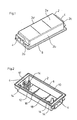
- Fig. 1
- eine perspektivische Ansicht von oben auf den Gehäusedeckel einer ersten Ausführungsform der Anschluss- und Verbindungsdose,
- Fig. 2
- eine perspektivische Ansicht von unten auf und in den Gehäusedeckel aus
Fig. 1 , - Fig. 3
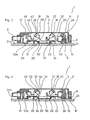
- einen Querschnitt quer zu dem Solarmodul durch die Anschluss- und Verbindungsdose gemäß der ersten Ausführungsform mit der elektrischen Anschlussvorrichtung im geöffneten Montagezustand,
- Fig. 4
- einen Querschnitt quer zu dem Solarmodul durch die Anschluss- und Verbindungsdose gemäß der ersten Ausführungsform mit der Anschlussvorrichtung im geschlossenen Kontaktzustand,
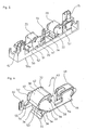
- Fig. 5
- eine perspektivische Darstellung zweier Anschlussvorrichtungen mit dem Bodenelement gemäß der ersten Ausführungsform,
- Fig. 6
- eine perspektivische vergrößerte Darstellung einer der Anschlussvorrichtungen aus
Fig. 5 , - Fig. 7
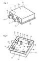
- eine perspektivische Ansicht von oben auf den Gehäusedeckel einer zweiten Ausführungsform der Anschluss- und Verbindungsdose,
- Fig. 8
- eine perspektivische Ansicht von unten auf und in den Gehäusedeckel aus
Fig. 7 , - Fig. 9
- einen Querschnitt quer zu dem Solarmodul durch die Anschluss- und Verbindungsdose gemäß der zweiten Ausführungsform mit der elektrischen Anschlussvorrichtung im geöffneten Montagezustand,
- Fig. 10
- einen Querschnitt quer zu dem Solarmodul durch die Anschluss- und Verbindungsdose aus
Fig. 9 mit der Anschlussvorrichtung im Zwischenzustand, - Fig. 11
- einen Querschnitt quer zu dem Solarmodul durch die Anschluss- und Verbindungsdose aus
Fig. 9 mit der Anschlussvorrichtung im geschlossenen Kontaktzustand und - Fig. 12
- eine perspektivische teilweise geschnittene Darstellung des Bodenelements mit zwei Anschlussvorrichtungen gemäß der zweiten Ausführungsform.
- Bezug nehmend auf die
Fig. 1-2 weist die Anschluss- und Verbindungsdose einen Gehäusedeckel 2 aus Kunststoff auf. Der Gehäusedeckel 2 wird gebildet von einem im Wesentlichen rechteckigen Rahmen aus vier Seitenwänden 2a bis 2d und einer die vier Seitenwände verbindenden und parallel zu dem Solarmodul verlaufenden, geschlossenen Deckelplatte 2e. Der fünfseitig geschlossene und nach unten offene Gehäusedeckel 2 ist z. B. einstückig aus Kunststoff gespritzt. In Anschlusskabeldurchführungen 4 werden jeweils separate Knickschutztüllen 6 (vgl.Fig. 3 und Fig. 4 ) eingesetzt. - Bezug nehmend auf
Fig. 2 ist der Gehäusedeckel 2 nach unten offen und weist einen nach außen vorragenden Befestigungsrahmen 8 mit einer umlaufenden Klebstoffnut 10 auf, so dass der Gehäusedeckel 2 eine hutartige Form besitzt. Mittels des in die Klebstoffnut 10 eingebrachten Klebstoffs wird die Anschluss- und Verbindungsdose letztlich auf dem Solarmodul dauerhaft festgeklebt. Die hut- oder wannenartige Form des Gehäusedeckels bildet einen inneren Hohlraum 12, in dem die inFig. 2 nicht dargestellten Anschlussvorrichtungen im montierten Zustand im Wesentlichen wasserdicht beherbergt werden. - Von der Unterseite der Deckelplatte 2e ragen Führungsstifte 14 in den Hohlraum 12. Auf der Innenseite der Anschlusskabeldurchführungen 4 ist zwischen zwei Führungsstiften 14 ein Klemmsteg 17 für das nicht dargestellte Anschlusskabel vorgesehen. Ferner weist die Unterseite der Deckelplatte 2e zwei Betätigungseinrichtungen 18 auf. Die Betätigungseinrichtungen 18, deren Funktion nachstehend noch genauer erläutert wird, sind in diesem Ausführungsbeispiel in Form von quer verlaufenden Betätigungsstegen ausgebildet, die einstückig mit dem Gehäusedeckel 2 ausgebildet sind.
- Bezug nehmend auf
Fig. 3 sind in dem von Gehäusedeckel 2 und Bodenelement 50 gebildeten Gehäuse 3 der Anschluss- und Verbindungsdose 1 zwei identische Anschlussvorrichtungen 20 angeordnet. Da die beiden Anschlussvorrichtungen 20 identisch ausgebildet sind, wird im Folgenden lediglich auf eine der beiden Anschlussvorrichtungen 20 Bezug genommen. -
Fig. 3 zeigt die Anschluss- und Verbindungsdose in dem Montagezustand, in dem die Kontaktklemme 22 geöffnet ist. Das Bodenelement 50 an welchem die Anschlussvorrichtung 20 befestigt ist, weist Führungshülsen 15 auf, in die die Führungsstifte 14 eingesetzt sind. Die Führungsstifte 14 klemmen in den zugehörigen Führungshülsen 15, derart, dass beim Aufsetzen der Anschluss- und Verbindungsdose 1 auf das Solarmodul 24 das Bodenelement 50 klemmend an dem Gehäusedeckel 2 festgehalten wird, so dass das Gehäuse 3 an dem Gehäusedeckel 2 von einem Roboter gefasst und automatisiert aufgesetzt werden kann, ohne dass das Bodenelement 50 und die Anschlussvorrichtung 20 herausfallen. Andererseits ist die Klemmung zwischen den Führungsstiften 14 und den Führungshülsen 15 durch Kraftbeaufschlagung überwindlich, um eine Relativverschiebung zwischen dem Gehäusedeckel 2 und dem Bodenelement 50 mit der Anschlussvorrichtung 20 zu ermöglichen, nämlich wenn eine Mindestkraft überschritten wird. Die Führungshülse 15 ist in diesem Beispiel geschlitzt, um die überwindlich klemmende Zusammenwirkung mit dem Führungsstift 14 zu verbessern. - In dem geöffneten Montagezustand ist die Anschlussvorrichtung 20 noch nicht vollständig in den Gehäusedeckel 2 eingeschoben und das Bodenelement 50 ragt noch ein Stück weit (einige Millimeter) aus dem Gehäusedeckel 2 nach unten, d.h. an der dem Solarmodul zugewandten Seite, heraus. Es besteht in dem Montagezustand also ein Versatz zwischen der Unterseite 50a des Bodenelements 50 und dem Befestigungsrahmen 8 des Gehäusedeckels 2, so dass beim Aufsetzen der Anschluss- und Verbindungsdose 1 zunächst das Bodenelement 50 mit dem Solarmodul 24 in Anlage kommt und in diesem in
Fig. 3 gezeigten Zustand der Befestigungsrahmen 8 noch von der Oberfläche 24a des Solarmoduls 24 beabstandet ist. - Das Bodenelement 50 weist eine relativ große Öffnung 26 an ihrer dem Solarmodul 24 zugewandten Unterseite 50a auf. Dies sorgt dafür, dass das empfindliche, flexible Flachleiterband 28, das sogenannte "Ribbon", in dem geöffneten Montagezustand hindernis- und widerstandsfrei von unten durch die Einführöffnung 26 in das Gehäuse 3 und die Anschlussvorrichtung 20 eingeführt werden kann. Hierdurch ist die Gefahr einer Beschädigung des Flachleiterbandes 28 reduziert. Die Kontaktklemme 22 definiert in diesem Zustand einen offenen Einfangraumbereich 31, in den das Flachleiterband 28 beim Aufsetzen der Anschluss- und Verbindungsdose von unten her widerstandsfrei eintaucht. Vorzugsweise findet in diesem Zustand noch keine Berührung zwischen der Kontaktklemme 22 und dem Flachleiterband 28 statt, so dass das Einführen und Kontaktieren des Flachleiterbandes 28 in zwei nacheinander folgenden Schritten stattfindet.
- Zum Schließen der Kontaktklemme wird nun der Gehäusedeckel 2 gegen das Solarmodul 24 kraftbeaufschlagt, wobei sich das Bodenelement 50 an dem Solarmodul 24 abstützt. Hierdurch kommt es zu einer linearen Relativverschiebung zwischen dem Gehäusedeckel 2 und dem Bodenelement 50 mit der Anschlussvorrichtung 20 dahingehend, dass der Gehäusedeckel 2 über das Bodenelement 50 und die Anschlussvorrichtung 20 geschoben wird, bis der Befestigungsrahmen 8 mit der Klebstoffnut 10 an der Oberfläche 24a des Solarmoduls 24 zur Anlage kommt und die Unterseite des Bodenelements 50 und des Gehäusedeckels 2 bündig an dem Solarmodul 24 anliegen. Dieser Zustand ist in
Fig. 4 dargestellt. - Bezug nehmend auf
Fig. 4 wird der Gehäusedeckel 2 mittels des in der Klebstoffnut 10 befindlichen Klebstoffs auf dem Solarmodul festgeklebt. Das Bodenelement 50 kann, muss aber nicht an dem Solarmodul 24 festgeklebt werden. Bei der Relativverschiebung des Gehäusedeckels 2 gegen das Bodenelement 50 und die Anschlussvorrichtung 20 wechselwirken ferner das Betätigungselement 18, in diesem Beispiel ein Betätigungssteg, mit der Klemmfeder 32. Durch diese Betätigung wird die Kontaktklemme 22 mittels einer Schwenkbewegung der Klemmfeder 32 geschlossen. Dabei überstreicht der Klemmabschnitt 34 der Klemmfeder 32 den Einfangraumbereich 31 und fängt das obere Ende des Flachleiterbandes 28 ein, um dieses zwischen dem Klemmabschnitt 34 der Klemmfeder 32 und dem Gegenklemmelement 36 elektrisch kontaktierend zu klemmen. Hierbei wird das Flachleiterband 28 abgewinkelt, da das Gegenklemmelement 36 in diesem Beispiel etwa unter 45° zur Solarmodulnormalen geneigt ist. - Die Klemmfeder 32 weist einen Betätigungsabschnitt 38 auf, der sich in einen gekrümmten Abschnitt 40 und einen im Wesentlichen geraden Abschnitt 42 unterteilt. Beim Schließen wirkt das Betätigungselement 18 zunächst auf den gekrümmten Abschnitt 40 (vgl.
Fig. 3 ) und spannt in dem inFig. 4 dargestellten, geschlossenen Kontaktzustand der Anschluss- und Verbindungsdose 1 gegen den geraden Abschnitt 42. D.h. das Betätigungselement 18 überstreicht beim Schließen den Betätigungsabschnitt 38 der Klemmfeder 32. - Die Anschlussvorrichtung 20 weist ferner eine Kabelanschlussklemme 46 für das nicht dargestellte elektrische Anschlusskabel auf.
- In diesem Beispiel ist die Kabelanschlussklemme 46 ebenfalls mit einer Klemmfeder 48 versehen, hier können jedoch auch andere Anschlussvarianten, wie z. B. Schraubklemmen, zum Einsatz kommen.
- In dem hier gezeigten Ausführungsbeispiel umfasst die Anschluss- und Verbindungsdose 1 zwei identisch ausgebildetet Anschlussvorrichtungen 20 zum gleichzeitigen Kontaktieren von zwei Flachleiterbändern 28. Es ist jedoch ersichtlich, dass die Erfindung hierauf nicht beschränkt ist und die Anschluss- und Verbindungsdose 1 auch nur eine oder mehr als zwei Anschlussvorrichtungen 20 umfassen kann.
- Bezug nehmend auf
Fig. 5 ist die Anschlussvorrichtung 20 an dem Bodenelement 50 befestigt, welches in diesem Beispiel in Form eines dielektrischen, vorzugsweise aus Kunststoff hergestellten Trägers ausgebildet ist. Die Unterseite 50a des Bodenelements 50 definiert die primäre Anlagefläche zu dem Solarmodul 24 und die Einführöffnung 26. Die Anschlussvorrichtung 20 besitzt ferner einen im Wesentlichen U-förmigen, metallischen Halterahmen 51, vorzugsweise aus Kupfer, der mit Rasthaken 52 an dem Bodenelement 50 verrastet ist. - Die
Fig. 5 und 6 zeigen die Kontaktklemme 22 in dem geschlossenen Kontaktzustand, in dem die Kontaktklemme 22 verrastet ist. Hierzu besitzt die Klemmfeder 32 zwei Rastzapfen 54, welche hinter korrespondierenden Vorsprüngen 55 in dem metallischen Halterahmen 51 eingerastet sind. In dem verrasteten Zustand ist die Kontaktfeder 32 gegen die Gegenklemme 36 vorgespannt. Dies sorgt für einen dauerhaften und sicheren elektrischen Kontakt. Das Flachleiterband 28 ist in denFig. 5 und 6 nicht dargestellt. - Ferner ist die Klemmfeder 32 mittels Lagerzapfen 56 in geschlitzten Lageröffnungen 58 aufgehängt. Somit kann die Klemmfeder 32 bei der Herstellung der Anschluss- und Verbindungsdose leicht eingesetzt werden und ist aufgrund der im Montagezustand und Kontaktzustand relativ zu dem Schlitz 60 gedrehten Position des flachen Lagerzapfens 56 gesichert. Die Klemmfeder 32 ist aus Stahlblech gestanzt und im wesentlichen U-förmig gebogen.
- Der metallische Halterahmen 51 weist ferner ein mittels einem Sockel 62 an dem Bodenelement 50 abgestütztes elektrisches Anschlusselement 64 für die Bypass-Diode auf.
- Aufgrund der Form der beiden Abschnitte 40, 42 des Betätigungsabschnitts 38 der Klemmfeder 32 wird in dem geöffneten Montagezustand die Klemmfeder 32 so fixiert, dass der Einfangraumbereich 31 im Montagezustand offen gehalten wird. Durch das Aufsetzen der Anschluss- und Verbindungsdose 1 auf das Solarmodul gelangt bei dem in
Fig. 1-6 dargestellten Ausführungsbeispiel das aus dem Solarmodul herausstehende Leiterband 28 von unten her unmittelbar in diesen Einfangraumbereich 31. - Durch das Zusammenwirken zwischen dem Gehäusedeckel 2 und dem Bodenelement 50 mit der Anschlussvorrichtung 20 vermittels des Betätigungselements 18 wird die Klemmfeder 32 gezwungen, die geöffnete Stellung zu verlassen, und wird in eine Schwenkbewegung versetzt.
- Das Flachleiterband 28, welches sich in dem Einfangraumbereich 31 befindet, wird von dem Klemmabschnitt 34 erfasst und durch die fortdauernde Schwenkbewegung in einem Winkel von, in diesem Beispiel 45°, gegen das Gegenklemmelement 36 gedrückt. Zum Ende der Schwenkbewegung rastet die Klemmfeder mit ihren Rastnasen 54 in dem Kontakt- oder Betriebszustand (
Fig. 4 ) in dem metallischen Halterahmen 51 ein. Durch die Vorspannung der Klemmfeder 32 wird eine dauerhafte und vordefinierte Andruckkraft zwischen dem Flachleiterband 28 und dem leitenden Gegenklemmelement 36 hergestellt. - Wieder Bezug nehmend auf
Fig. 2 sind bei diesem Beispiel vier Führungsstifte 14 vorgesehen, um die Anschlussvorrichtung 20 mit dem Bodenelement 50 an lateral unterschiedlichen Postionen in dem Gehäusedeckel 2 anordnen zu können. - Die
Fig. 7 und 8 zeigen eine Anschluss- und Verbindungsdose 1 gemäß einer zweiten Ausführungsform der Erfindung, bei der der Gehäusedeckel 2 eher quadratisch ausgebildet, um zwei Anschlussvorrichtungen 20 nebeneinander statt hintereinander wie bei der ersten Ausführungsform (Fig. 1-6 ) anzuordnen. Da die Kontaktklemme 22 und die Verschiebeeinrichtung 14, 15 bei dem ersten und zweiten Ausführungsbeispiel weitestgehend gleich ausgebildet sind, wird auf die vorstehende Beschreibung zum ersten Ausführungsbeispiel verwiesen, um Wiederholungen zu vermeiden. - Die Unterseite der Deckelplatte 2e weist eine erste Betätigungseinrichtung 16 in Form einer seitlichen Nocke zur Betätigung des Umlenkhebels auf (in
Fig. 8 nicht dargestellt, vgl. hierzuFig. 9-11 ). Ferner ragen Betätigungsstifte 18 zur Betätigung der Kontaktklemmen von der Deckelplatte 2e in den Innenraum 12 des Gehäusedeckels 2. Die Nocke 16 und die Betätigungseinrichtung 18 sind in diesem Ausführungsbeispiel einstückig mit dem Gehäusedeckel 2 ausgebildet. - Bezug nehmend auf die
Fig. 9-11 ist in dem Gehäuse 3 der Anschluss- und Verbindungsdose 1 die Anschlussvorrichtung 20 angeordnet. Bezug nehmend aufFig. 12 besitzt diese Anschluss- und Verbindungsdose ebenfalls zwei identische Anschlussvorrichtungen 20, wobei im Folgenden lediglich auf eine der beiden Bezug genommen wird. -
Fig. 9 zeigt die Anschluss- und Verbindungsdose nachdem diese über das Flachleiterband 28 gestülpt wurde. Die Anschluss- und Verbindungsdose befindet sich beim Überstülpen in einem ersten Zustand, dem Montagezustand, in dem sich der Umlenkhebel 21 in einer ersten Stellung befindet. In dem Montagezustand, in dem die Anschluss- und Verbindungsdose vorzugsweise ausgeliefert wird, ist der Zwischenraumbereich 30 über der Einführöffnung 26 freigehalten und die Kontaktklemme 22 geöffnet. - Die Anschluss- und Verbindungsdose 1 weist eine relativ große Einführöffnung 26 an ihrer dem Solarmodul 24 zugewandten Unterseite auf. Dies sorgt dafür, dass das empfindliche, flexible Flachleiterband 28, das sogenannte "Ribbon", in dem Montagezustand hindernis- und widerstandsfrei von unten in die Anschluss- und Verbindungsdose 1 eingeführt wird. Hierdurch ist die Gefahr einer Beschädigung des Flachleiterbandes 28 reduziert. Die Anschluss- und Verbindungsdose 1 definiert in diesem Zustand einen zwischen der Kontaktklemme 22 und dem Umlenkhebel 21 befindlichen offenen Zwischen- oder Einführraumbereich 30, in den das Flachleiterband 28 beim Aufsetzen der Anschluss- und Verbindungsdose von unten her widerstandsfrei eintaucht. Vorzugsweise findet in diesem Zustand noch keine Berührung zwischen der Kontaktklemme 22 oder dem Umlenkhebel 21 und dem Flachleiterband 28 statt.
- Zum Kontaktieren des Flachleiterbandes 28 wird nun der Gehäusedeckel 2 gegen das Solarmodul 24 kraftbeaufschlagt, wobei die Anschlussvorrichtung 20 sich an dem Solarmodul 24 abstützt. Hierdurch kommt es zu einer linearen Relativverschiebung zwischen dem Gehäusedeckel 2 und dem Bodenelement 50 mit der Anschlussvorrichtung 20 dahingehend, dass der Gehäusedeckel 2 über die Anschlussvorrichtung 20 geschoben wird, bis der Befestigungsrahmen 8 mit dem in der Klebstoffnut 10 befindlichen Klebstoff (nicht dargestellt) an der Oberfläche des Solarmoduls 24 zur Anlage kommt und die Unterseite 50a des Bodenelements 50 und des Gehäusedeckels 2 bündig an dem Solarmodul 24 anliegen. Dieser geschlossene Kontaktzustand stellt den End- oder Betriebszustand dar und ist in
Fig. 11 dargestellt. In dem Betriebszustand ist das Gehäuse 3 mittels des in der Klebstoffnut 10 befindlichen Klebstoffs auf dem Solarmodul 24 festgeklebt. - Bevor die Anschluss- und Verbindungsdose 1 jedoch in den Endzustand gelangt, durchläuft sie noch den in
Fig. 10 dargestellten Zwischenzustand, in welchem das Flachleiterband 28 bereits umgebogen ist und die Kontaktklemme 22 noch geöffnet ist. Es wird also beim Aufsetzen der Anschluss- und Verbindungsdose 1 zunächst das Flachleiterband 28 in den Einführraumbereich 30 eingeführt, nachfolgend wird, nachdem die Unterseite 50a des Bodenelements 50 auf dem Solarmodul 24 zur Anlage gekommen ist, das Flachleiterband 28 mittels des Umlenkhebels 21 in den Einfangraumbereich 31 der Kontaktklemme 22 umgebogen. Weiter nachfolgend wird die Kontaktklemme 22 aktiv mittels des zweiten Betätigungselements 18 geschlossen. Somit definiert die Anschluss- und Verbindungsdose 1 drei vordefinierte Zustände, nämlich den Montagezustand (Fig. 9 ), in dem sich der Umlenkhebel 21 in einer ersten Position befindet, so dass der Einführraumbereich 30 frei ist und die Kontaktklemme 22 geöffnet ist; den Zwischenzustand (Fig. 10 ), in dem das Flachleiterband 28 von dem Umlenkhebel 21 in den Einfangraumbereich 31 der noch immer geöffneten Kontaktaktklemme 22 umgebogen ist; und den End- oder Betriebszustand (Fig. 11 ), in dem die Kontaktklemme 22 geschlossen ist, und den elektrischen Kontakt mit dem Flachleiterband 28 mittels Klemmkontaktierung herstellt. Bei dieser Ausführungsform erfolgt die Kontaktierung des Flachleiterbandes 28 parallel zur Oberfläche des Solarmoduls 24. - Bei der Relativverschiebung des Gehäusedeckels 2 gegen das Bodenelement 50 und die Anschlussvorrichtung 20 wechselwirken demnach zunächst das erste Betätigungselement 16, in diesem Beispiel eine Betätigungsnocke, mit dem Umlenkhebel 21 und nachfolgend das zweite Betätigungselement 18, in diesem Beispiel ein Betätigungsstift, mit der Klemmfeder 32. Durch diese sukzessive Betätigung wird zunächst der Biegeabschnitt 21a des Umlenkhebels 21 in Ansprechen auf eine Betätigung mittels der Nocke 16 ausgelenkt und nachfolgend die Kontaktklemme 22 mittels einer Schwenkbewegung der Klemmfeder 32 geschlossen. Die Nocke 16 ist in diesem Beispiel als Vorsprung der Seitenwand des Gehäusedeckels 2 einstückig mit diesem ausgebildet. Nachfolgend überstreicht der Klemmabschnitt 34 der Klemmfeder 32 den Einfangraumbereich 31 der Kontaktklemme und klemmt und kontaktiert freie Ende des Flachleiterbandes 28 zwischen dem Klemmabschnitt 34 der Klemmfeder 32 und dem Gegenklemmelement 36. Der Biegeabschnitt 21a des Umlenkhebels 21 ist einstückig mittels einem Falzscharnier 21b mit einem Halteabschnitt 21c verbunden. Der Halteabschnitt 21c ist an dem Bodenelement 50 befestigt, genauer einstückig mit diesem ausgebildet.
- Bezug nehmend auf
Fig. 12 umfasst die Anschluss- und Verbindungsdose 1 in diesem Beispiel zwei Anschlussvorrichtungen 20. Die Anschlussvorrichtungen 20 sind oberseitig an dem dielektrischen Bodenelement 50 befestigt.Fig. 12 zeigt die Kontaktklemme 22 in dem geöffneten Montagezustand. Die Klemmfeder 32 weist zwei Rastzapfen 54 auf, welche in dem geöffneten Montagezustand jeweils in Vertiefungen 53 in dem metallischen Halterahmen 51 überwindbar festgeklemmt sind. - Wieder Bezug nehmend auf
Fig. 9-11 werden durch das Zusammenwirken zwischen dem Gehäusedeckel 2 und dem Kunststoff-Bodenelement 50 mit der daran befestigten Anschlussvorrichtung 20 vermittels der Betätigungselemente 16 und 18 nacheinander der Biegeabschnitt 21a des Umlenkhebels 21 und die Klemmfeder 32 in eine Schwenkbewegung versetzt. Zum Ende der Schwenkbewegung rastet die Klemmfeder mit ihren Rastnasen 54 in dem Kontaktzustand (Fig. 11 ) hinter Vorsprüngen 55 in dem metallischen Halterahmen 51 ein. Durch die Vorspannung der Klemmfeder 32 wird eine dauerhafte und vordefinierte Andruckkraft zwischen dem Flachleiterband 28 und dem leitenden Gegenklemmelement 36 hergestellt. - Es ist dem Fachmann ersichtlich, dass die vorstehend beschriebenen Ausführungsformen beispielhaft zu verstehen sind, und die Erfindung nicht auf diese beschränkt ist, sondern in vielfältiger Weise variiert werden kann, ohne den durch die Patentansprüche bestimmten Schutzbereich zu verlassen. Insbesondere kann die Anschluss- und Verbindungsdose eine oder eine Mehrzahl von Kontaktklemmen aufweisen, um eine oder eine Mehrzahl von Flachleiterbändern in der Anschluss- und Verbindungsdose zu kontaktieren. Ferner ist ersichtlich, dass die Merkmale unabhängig davon, ob sie in der Beschreibung, den Ansprüchen, den Figuren oder anderweitig offenbart sind auch einzeln wesentliche Bestandteile der Erfindung definieren, selbst wenn sie zusammen mit anderen Merkmalen gemeinsam beschrieben sind.
Claims (14)
- Anschluss- und Verbindungsdose (1) für ein photovoltaisches Solarmodul (24) mit zumindest einem flexiblen Flachleiterband (28), das aus der Oberfläche des Solarmoduls herausragt, umfassend
ein dielektrisches Gehäuse (3) zum Aufsetzen auf das Solarmodul (24) und mit einer Einführöffnung (26) an der im montierten Zustand dem Solarmodul (24) zugewandten Seite (50a) des Gehäuses (3) zum Einführen des Flachleiterbands (28) in das Gehäuse (3),
eine von dem Gehäuse (3) beherbergte Anschlussvorrichtung (20) mit einer Kontaktklemme (22) zum elektrischen Kontaktieren des flexiblen Flachleiterbands (28),
wobei die Anschluss- und Verbindungsdose (1) einen Montagezustand und einen Kontaktzustand definiert,
dadurch gekennzeichnet, dass
die Kontaktklemme (22) in dem Montagezustand geöffnet ist, um das flexible Flachleiterband (28) in die geöffnete Kontaktklemme (22) einführen zu können,
die Kontaktklemme (22) in dem Kontaktzustand geschlossen ist, um das flexible Flachleiterband (28) elektrisch zu kontaktieren,
das Gehäuse (3) zumindest zweiteilig ausgebildet ist und die beiden Gehäuseteile (2, 50) relativ zueinander bewegbar sind und
die Anschluss- und Verbindungsdose (1) eine Betätigungseinrichtung (18) zum Schließen der Kontaktklemme (22) aufweist, wobei die Betätigungseinrichtung (18) in Ansprechen auf eine Relativbewegung zwischen den beiden Gehäuseteilen (2, 50) automatisch die.Kontaktklemme (22) schließt, um das flexible Flachleiterband (28) zu kontaktieren, wenn die Anschluss- und Verbindungsdose (1) auf das Solarmodul (24) aufgesetzt und das flexible Flachleiterband (28) in das Gehäuse (3) eingeführt ist. - Anschluss- und Verbindungsdose (1) nach Anspruch 1, wobei das Gehäuse (3) eine Verschiebeeinrichtung (14, 15) aufweist, mittels welcher die beiden Gehäuseteile (2, 50) quer zu der Oberfläche (24a) des Solarmoduls (24) relativ zueinander verschiebbar sind und die Betätigungseinrichtung (18) in Ansprechen auf eine Relativverschiebung zwischen den beiden Gehäuseteilen (2, 50) automatisch die Kontaktklemme (22) schließt, um das flexible Flachleiterband (28) zu kontaktieren.
- Anschluss- und Verbindungsdose (1) nach Anspruch 2, wobei die Verschiebeeinrichtung (14, 15) eine Mehrzahl von in Führungshülsen (15) geführten Führungsstiften (14) aufweist, welche an den beiden Gehäuseteilen (2, 50) vorgesehen sind.
- Anschluss- und Verbindungsdose (1) nach Anspruch 2 oder 3, wobei die Verschiebeeinrichtung (14, 15) in dem Montagezustand selbsthemmend ausgebildet ist, derart dass beim Fassen und Handhaben lediglich eines der beiden Gehäuseteile (2) das andere Gehäuseteil (50) nicht herausfällt.
- Anschluss- und Verbindungsdose (1) nach Anspruch 2, 3 oder 4, wobei in dem Montagezustand das erste (50) der beiden Gehäuseteile an der dem Solarmodul zugewandten Seite über das zweite (2) der beiden Gehäuseteile hinausragt, derart dass beim Aufsetzen der Anschluss- und Verbindungsdose (1) auf das Solarmodul (24) zunächst nur das erste Gehäuseteil (50) an dem Solarmodul (24) zur Anlage kommt, und wobei durch Kraftbeaufschlagung auf das zweite Gehäuseteil (2) in Richtung des Solarmoduls (24) die Relativverschiebung des zweiten Gehäuseteils (2) gegenüber dem ersten Gehäuseteil (50) bewirkt wird, um mittels der Betätigungseinrichtung (18) die Kontaktklemme (22) zu schließen.
- Anschluss- und Verbindungsdose (1) nach einem der vorstehenden Ansprüche, wobei das Gehäuse (3) zumindest zweiteilig ausgebildet ist und das erste (50) der beiden Gehäuseteile als Bodenelement zur Anlage an das Solarmodul und das zweite (2) der beiden Gehäuseteile als Deckelteil ausgebildet ist und zumindest eines der beiden Gehäuseteile (2, 50) umlaufende Seitenwände (2a-d) aufweist, so dass das erste und zweite Gehäuseteil (2, 50) gemeinsam, abgesehen von vordefinierten Öffnungen, eine geschlossene und zumindest spritzwasserdichte Box für die Anschlussvorrichtung (1) definiert, wenn das Gehäuse (3) in dem Kontaktzustand mit dem Solarmodul (24) fest verbunden ist.
- Anschluss- und Verbindungsdose (1) nach Anspruch 6, wobei das Deckelteil (2) einen umlaufenden Rand (8) mit einer Klebstoffnut (10) aufweist, um das Deckelteil (2) auf der Oberfläche (24a) des Solarmoduls (24) festzukleben.
- Anschluss- und Verbindungsdose (1) nach einem der vorstehenden Ansprüche, wobei die Kontaktklemme (22) als eine Federkraftklemme mit einer Klemmfeder (32) und einem Gegenklemmelement (36) ausgebildet ist, wobei die Federkraftklemme im Montagezustand von sich aus geöffnet ist und durch Kraftbeaufschlagung mittels der
Betätigungseinrichtung (18) schließbar ist. - Anschluss- und Verbindungsdose (1) nach Anspruch 8, wobei die Klemmfeder (32) und/oder das Gegenklemmelement (36) schwenkbar an der Anschlussvorrichtung (20) gelagert ist und der elektrische Kontakt mit dem flexiblen Flachleiterband (28) mittels einer Schwenkbewegung zumindest eines der Klemmfeder (32) oder des Gegenklemmelementes (36) in Ansprechen auf die Betätigung mittels der Betätigungseinrichtung (18) geschlossen wird.
- Anschluss- und Verbindungsdose (1) nach einem der vorstehenden Ansprüche, wobei die Kontaktklemme (22) einen Rastmechanismus (54, 55) aufweist, mittels welchem die Klemmfeder (32) in dem Kontaktzustand verrastet ist.
- Anschluss- und Verbindungsdose (1) nach einem der vorstehenden Ansprüche, wobei beim Aufsetzen der Anschluss- und Verbindungsdose das flexible Flachleiterband (28) durch die Einführöffnung (26) hindurch im Wesentlichen widerstandsfrei entweder
direkt in den offenen Einfangraumbereich (1) der geöffneten Kontaktklemme (22) eingeführt wird oder
in einen offenen Zwischenraumbereich (30) in dem Gehäuse (3) eingeführt wird und die Anschluss- und Verbindungsdose (1) eine Umlenkeinrichtung (21) für das flexible Flachleiterband (28) aufweist, welche das flexible Flachleiterband (28) von dem Zwischenraumbereich (30) in den Einfangraumbereich (31) der Kontaktklemme umlenkt. - Photovoltaisches Solarmodul (24) mit zumindest einem aus der Oberfläche (24a) herausragenden flexiblen Flachleiterband (28), und zumindest einer auf das Solarmodul (24) montierten Anschluss- und Verbindungsdose (1) gemäß einem der vorstehenden Ansprüche.
- Verfahren zum Anschließen einer Anschluss- und Verbindungsdose (1) an ein photovoltaisches Solarmodul, umfassend die Schritte:Bereitstellen eines Solarmoduls (24) mit zumindest einem flexiblen Flachleiterband (28), das aus der Oberfläche (24a) des Solarmoduls (24) herausragt,Bereitstellen einer Anschluss- und Verbindungsdose (1), welche ein Gehäuse (3) sowie eine in dem Gehäuse (3) angeordnete Anschlussvorrichtung (20) mit einer elektrischen Kontaktklemme (22) zum Herstellen eines Klemmkontaktes mit dem flexiblen Flachleiterband (28) umfasst, und eine Einführöffnung (26) an der Unterseite der Anschluss- und Verbindungsdose (1) sowie eine Betätigungseinrichtung (18) zum Betätigen der Kontaktklemme (22) aufweist,Aufsetzen der Anschluss- und Verbindungsdose (1) auf das Solarmodul (24), wobei die Anschluss- und Verbindungsdose (1) mit der Einführöffnung (26) über das flexible Flachleiterband (28) gestülpt wird,Einführen des flexiblen Flachleiterbandes (28) in den Einfangraumbereich (31) der geöffneten Kontaktklemme (22) entweder unmittelbar beim oder nach dem Überstülpen der Anschluss- und Verbindungsdose (1) über das flexible Flachleiterband (28),Bewirken einer Relativbewegung zwischen zwei Gehäuseteilen (2, 50), wodurch die Kontaktklemme (22) mittels der Betätigungseinrichtung (18) geschlossen wird und hierbei das flexible Flachleiterband (28) kontaktiert wird.
- Verfahren nach Anspruch 13, wobei das Gehäuse (3) ein Bodenelement (50) und ein Deckelteil (2) umfasst, wobei die Anschlussvorrichtung (20) an dem Bodenelement (50) befestigt ist und zusammen mit dem Bodenelement (50) relativ zu dem Deckelteil (2) verschiebbar ist, wobei die Verschiebeeinrichtung (14, 15) überwindbar selbsthemmend ausgelegt ist, so dass das Bodenelement (50) und die Anschlussvorrichtung (20) beim Aufsetzen der Anschluss- und Verbindungsdose (1) auf das Solarmodul (24) nicht von dem Deckelteil (2) abfallen, wobei das Bodenelement (50) in dem Montagezustand nach unten aus dem Deckelteil (2) herausragt, so dass beim Aufsetzen auf das Solarmodul (24) zunächst nur das Bodenelement (50) mit der Oberfläche (24a) des Solarmoduls (24) zur Anlage gebracht wird,
wobei das Deckelteil (2) in Richtung des Solarmoduls (24) kraftbeaufschlagt wird, derart, dass das Deckelteil (2) relativ zu dem Bodenelement (50) und der Anschlussvorrichtung (20) verschoben wird, bis das Deckelteil (2) ebenfalls an dem Solarmodul (24) zur Anlage kommt, wobei die Kontaktklemme (22) in Ansprechen auf die Relativverschiebung zwischen dem Deckelteil (2) und dem Bodenelement (50) automatisch geschlossen wird.
Applications Claiming Priority (5)
| Application Number | Priority Date | Filing Date | Title |
|---|---|---|---|
| DE102007006433A DE102007006433A1 (de) | 2007-02-05 | 2007-02-05 | Anschlußbox für den elektrischen Anschluß eines Solarmoduls und Verfahren zur Montage einer Anschlußbox auf einem Solarmodul |
| DE102007037130A DE102007037130B3 (de) | 2007-08-07 | 2007-08-07 | Anschluss- und Verbindungsdose für ein Solarmodul |
| DE102007042547 | 2007-09-07 | ||
| DE102007051134A DE102007051134B4 (de) | 2007-09-07 | 2007-10-24 | Anschluss- und Verbindungsdose für ein Solarmodul |
| PCT/EP2008/000859 WO2008095670A1 (de) | 2007-02-05 | 2008-02-04 | Anschluss- und verbindungsdose für ein solarmodul |
Publications (2)
| Publication Number | Publication Date |
|---|---|
| EP2118977A1 EP2118977A1 (de) | 2009-11-18 |
| EP2118977B1 true EP2118977B1 (de) | 2012-06-20 |
Family
ID=41153234
Family Applications (2)
| Application Number | Title | Priority Date | Filing Date |
|---|---|---|---|
| EP08707533A Withdrawn EP2115838A1 (de) | 2007-02-05 | 2008-02-04 | Anschluss- und verbindungsdose für ein solarmodul |
| EP08707534A Not-in-force EP2118977B1 (de) | 2007-02-05 | 2008-02-04 | Anschluss- und verbindungsdose für ein solarmodul |
Family Applications Before (1)
| Application Number | Title | Priority Date | Filing Date |
|---|---|---|---|
| EP08707533A Withdrawn EP2115838A1 (de) | 2007-02-05 | 2008-02-04 | Anschluss- und verbindungsdose für ein solarmodul |
Country Status (7)
| Country | Link |
|---|---|
| US (1) | US8366471B2 (de) |
| EP (2) | EP2115838A1 (de) |
| JP (1) | JP5441716B2 (de) |
| CN (1) | CN101606293B (de) |
| DK (1) | DK2118977T3 (de) |
| ES (1) | ES2385112T3 (de) |
| WO (2) | WO2008095670A1 (de) |
Cited By (1)
| Publication number | Priority date | Publication date | Assignee | Title |
|---|---|---|---|---|
| DE102020100893A1 (de) | 2020-01-16 | 2021-07-22 | Phoenix Contact Gmbh & Co. Kg | Anschlussklemme |
Families Citing this family (30)
| Publication number | Priority date | Publication date | Assignee | Title |
|---|---|---|---|---|
| DE102008061268B4 (de) * | 2008-12-10 | 2017-02-23 | Phoenix Contact Gmbh & Co. Kg | Kontaktklemme und Verbinder mit Kontaktklemme |
| DE102008062034B4 (de) * | 2008-12-12 | 2010-08-12 | Tyco Electronics Amp Gmbh | Verbindungsvorrichtung zum Anschluss an ein Solarmodul und Solarmodul mit einer solchen Verbindungsvorrichtung |
| US8435056B2 (en) | 2009-04-16 | 2013-05-07 | Enphase Energy, Inc. | Apparatus for coupling power generated by a photovoltaic module to an output |
| JP5146406B2 (ja) * | 2009-05-27 | 2013-02-20 | 住友電装株式会社 | 太陽電池モジュール用端子ボックス |
| ES2376517T3 (es) | 2009-07-03 | 2012-03-14 | Tyco Elektronics Amp Gmbh | Caja de empalmes para la conexión de una célula solar, diodo eléctrico, elemento de gu�?a y medios de fijación. |
| CN102035157B (zh) * | 2009-09-25 | 2013-02-27 | 无锡尚德太阳能电力有限公司 | 一种太阳电池组件用接线盒及太阳电池组件 |
| CN101783488B (zh) * | 2010-01-19 | 2012-01-04 | 浙江大学 | 分离式太阳能组件接线盒 |
| WO2011109109A1 (en) * | 2010-03-05 | 2011-09-09 | Xunlight Corporation | Terminal assembly including a junction box for a photovoltaic module and method of forming |
| EP2649683A1 (de) * | 2010-12-09 | 2013-10-16 | Multi-Holding AG | Kontaktelement, insbesondere lötregister und fotovoltaik-anschlussbox mit kontaktelement, insbesondere ein lötregister |
| WO2012083049A1 (en) * | 2010-12-17 | 2012-06-21 | First Solar, Inc | Electrical connection system |
| DE102011009005B4 (de) * | 2011-01-14 | 2014-07-31 | Solon Se | Elektrische Anschlussdose für ein Photovoltaikmodul |
| DE102011004369B4 (de) * | 2011-02-18 | 2017-08-24 | SolarWorld Industries Thüringen GmbH | Anschlussdose und Satz von Anschlussdosen sowie Solarzellenanordnung |
| US9118273B2 (en) | 2011-07-18 | 2015-08-25 | Enphase Energy, Inc. | Resilient mounting assembly for photovoltaic modules |
| US20130048334A1 (en) * | 2011-08-29 | 2013-02-28 | Tyco Electronics Corporation | Junction box |
| KR101283628B1 (ko) * | 2011-09-05 | 2013-07-08 | 주식회사 씨엔플러스 | 정션박스 |
| JP5729648B2 (ja) * | 2011-10-13 | 2015-06-03 | ホシデン株式会社 | 太陽電池モジュール用端子ボックス |
| GB2502801B (en) * | 2012-06-07 | 2014-11-26 | Jaguar Land Rover Ltd | Insulating sock of a traction battery |
| USD734653S1 (en) | 2012-11-09 | 2015-07-21 | Enphase Energy, Inc. | AC module mounting bracket |
| US10402922B2 (en) * | 2014-04-10 | 2019-09-03 | Vivint Solar, Inc. | Photovoltaic system installation |
| CN103944504A (zh) * | 2014-04-25 | 2014-07-23 | 江苏九鼎光伏系统有限公司 | 接插式光伏电池组件接线盒及其接线安装方法 |
| JP6283278B2 (ja) | 2014-07-18 | 2018-02-21 | ホシデン株式会社 | 端子ボックス及び出力線の接続方法 |
| JP6156308B2 (ja) * | 2014-09-24 | 2017-07-05 | 住友電装株式会社 | 電気接続箱 |
| US10476429B2 (en) | 2015-06-29 | 2019-11-12 | Te Connectivity Corporation | Solar junction box |
| JP6726074B2 (ja) | 2016-09-30 | 2020-07-22 | オムロン株式会社 | 端子台 |
| US11063375B2 (en) | 2017-12-06 | 2021-07-13 | Zeon Corporation | Connection instrument |
| USD879040S1 (en) * | 2018-04-03 | 2020-03-24 | Electro Expo Limited | Electrical connection box |
| CN110336232B (zh) * | 2019-07-24 | 2020-10-02 | 扬州利家科技有限公司 | 一种接线效率高的防爆接线盒 |
| CN113161954B (zh) * | 2021-03-31 | 2022-09-30 | 商丘工学院 | 一种电气工程用电缆配接器装置 |
| FR3128066B1 (fr) * | 2021-10-07 | 2024-09-13 | Tyco Electronics France Sas | Dispositif de connexion électrique |
| CN120221221B (zh) * | 2025-05-26 | 2025-08-12 | 聚变新能(安徽)有限公司 | 一种接电板、馈电接头、馈电接头保护机构以及真空压力浸渍模具 |
Family Cites Families (19)
| Publication number | Priority date | Publication date | Assignee | Title |
|---|---|---|---|---|
| US4460232A (en) * | 1982-05-24 | 1984-07-17 | Amp, Incorporated | Junction box for solar modules |
| JP3424559B2 (ja) * | 1998-08-20 | 2003-07-07 | 住友電装株式会社 | 太陽電池モジュールの端子ボックスおよびその端子ボックスを用いた配線システム |
| JP3838789B2 (ja) * | 1998-09-11 | 2006-10-25 | 旭化成建材株式会社 | 太陽電池モジュール、太陽電池モジュールの作成方法、太陽電池モジュールの取り付け構造、および太陽電池付き屋根材 |
| JP4080607B2 (ja) * | 1998-09-16 | 2008-04-23 | スタンレー電気株式会社 | Led取付装置 |
| EP1102354B1 (de) * | 1999-11-17 | 2008-05-28 | Tyco Electronics AMP GmbH | Vorrichtung zur Verbindung von Leiterfolien, insbesondere von einem Solarmodul |
| JP2002359389A (ja) * | 2001-05-31 | 2002-12-13 | Kitani Denki Kk | 太陽光発電モジュール配線用端子ボックス |
| DE20311184U1 (de) | 2003-07-21 | 2004-02-19 | Tyco Electronics Amp Gmbh | Anschlussdose zum Anschließen an ein Solarpaneel |
| DE10358140B4 (de) | 2003-12-10 | 2006-01-05 | Günther Spelsberg GmbH & Co. KG | Elektrische Anschluß- und Verbindungsdose für ein Solarzellenmodul |
| JP4798956B2 (ja) * | 2004-03-29 | 2011-10-19 | 京セラ株式会社 | 太陽電池モジュールおよびそれを用いた太陽光発電装置 |
| DE102004020958B3 (de) * | 2004-04-28 | 2005-08-25 | Rose Systemtechnik Gmbh | Anschlußklemme und damit gebildete Anschlußbox |
| JP3767618B2 (ja) * | 2004-08-19 | 2006-04-19 | 住友電装株式会社 | 太陽電池モジュール用端子ボックス |
| ATE527694T1 (de) | 2004-12-16 | 2011-10-15 | Spelsberg Guenther Gmbh Co Kg | Elektrische anschluss- und verbindungsdose für ein solarzellenmodul |
| JP2006278425A (ja) | 2005-03-28 | 2006-10-12 | Sharp Corp | 太陽光発電システム |
| DE102005025632B4 (de) | 2005-06-03 | 2015-09-17 | Te Connectivity Germany Gmbh | Verbindungsvorrichtung für den Anschluss elektrischer Folienleiter |
| DE202005018884U1 (de) | 2005-12-02 | 2006-02-09 | Multi-Holding Ag | Anschlussdose für ein Solarpaneel sowie Solarpaneel mit einer solchen Anschlussdose |
| WO2007118798A2 (de) | 2006-04-13 | 2007-10-25 | Weidmüller Interface GmbH & Co. KG | Elektrische anschlussvorrichtung für flachleiter |
| DE202007005126U1 (de) * | 2007-04-04 | 2008-08-14 | Weidmüller Interface GmbH & Co. KG | Elektrische Anschlußvorrichtung für Kontakte, insbesondere Messerkontakte |
| ES2380205T3 (es) * | 2008-08-29 | 2012-05-09 | Heyco, Inc. | Caja de empalmes para sistemas fotovoltaicos |
| DE202009004930U1 (de) * | 2008-09-22 | 2010-03-04 | Weidmüller Interface GmbH & Co. KG | Elektrische Anschlussvorrichtung für Flachleiter |
-
2008
- 2008-02-04 US US12/525,794 patent/US8366471B2/en not_active Expired - Fee Related
- 2008-02-04 EP EP08707533A patent/EP2115838A1/de not_active Withdrawn
- 2008-02-04 DK DK08707534.7T patent/DK2118977T3/da active
- 2008-02-04 WO PCT/EP2008/000859 patent/WO2008095670A1/de not_active Ceased
- 2008-02-04 EP EP08707534A patent/EP2118977B1/de not_active Not-in-force
- 2008-02-04 CN CN2008800040872A patent/CN101606293B/zh not_active Expired - Fee Related
- 2008-02-04 WO PCT/EP2008/000858 patent/WO2008095669A1/de not_active Ceased
- 2008-02-04 JP JP2009548614A patent/JP5441716B2/ja not_active Expired - Fee Related
- 2008-02-04 ES ES08707534T patent/ES2385112T3/es active Active
Cited By (1)
| Publication number | Priority date | Publication date | Assignee | Title |
|---|---|---|---|---|
| DE102020100893A1 (de) | 2020-01-16 | 2021-07-22 | Phoenix Contact Gmbh & Co. Kg | Anschlussklemme |
Also Published As
| Publication number | Publication date |
|---|---|
| ES2385112T3 (es) | 2012-07-18 |
| JP2010518614A (ja) | 2010-05-27 |
| CN101606293B (zh) | 2013-11-13 |
| EP2115838A1 (de) | 2009-11-11 |
| JP5441716B2 (ja) | 2014-03-12 |
| WO2008095670A1 (de) | 2008-08-14 |
| WO2008095669A1 (de) | 2008-08-14 |
| CN101606293A (zh) | 2009-12-16 |
| DK2118977T3 (da) | 2012-10-01 |
| EP2118977A1 (de) | 2009-11-18 |
| US20100173511A1 (en) | 2010-07-08 |
| US8366471B2 (en) | 2013-02-05 |
| WO2008095670A8 (de) | 2012-03-01 |
Similar Documents
| Publication | Publication Date | Title |
|---|---|---|
| EP2118977B1 (de) | Anschluss- und verbindungsdose für ein solarmodul | |
| DE102007051134B4 (de) | Anschluss- und Verbindungsdose für ein Solarmodul | |
| DE102007037130B3 (de) | Anschluss- und Verbindungsdose für ein Solarmodul | |
| EP2115839A1 (de) | Anschluss- und verbindungsdose für ein solarmodul | |
| DE102008003448B4 (de) | Anschlußdose, Verwendung, Solarpaneel, Kontaktelement, und Verfahren | |
| DE102009033481B4 (de) | Anschluss- und Verbindungsvorrichtung | |
| DE69333735T2 (de) | Photovoltaisches dachbedeckungssystem | |
| EP1941550B1 (de) | Solarstromsystem mit einer mehrzahl von photovoltaikmodulen | |
| DE102010029714A1 (de) | Elektrische Federklemmeinrichtung, Stanzgitter, Stromschiene und elektrische Anschlussvorrichtung | |
| DE102007043178A1 (de) | Anschlußdose, Solarpaneel, Kontaktvorrichtung und Verfahren | |
| DE102007006433A1 (de) | Anschlußbox für den elektrischen Anschluß eines Solarmoduls und Verfahren zur Montage einer Anschlußbox auf einem Solarmodul | |
| DE102010024350A1 (de) | Anschlusseinrichtung für Photovoltaikmodule und Verfahren zu deren Montage | |
| DE102012102214B3 (de) | Solarmodul mit Anschlusselementen, Solarmodulsystem und Verfahren zur Montage und Verbindung eines Solarmoduls | |
| DE102007032603A1 (de) | Anschlußkontakt und Verfahren zum Laminieren von mit elektrischen Anschlußkontakten versehenen Gegenständen | |
| DE202010000052U1 (de) | Photovoltaikmodul mit einer Anschlussdose | |
| EP2296181B1 (de) | Anschlußdose, deren Verwendung in einem Solarpaneel und Herstellungsverfahren | |
| EP2386125B1 (de) | Solarpaneel und verfahren zu dessen herstellung | |
| DE102013209839A1 (de) | Verbindungsanordnung an einer Solarzelleneinheit und Stromerzeugungseinheit | |
| EP2549552A2 (de) | Solarzellenbaustein und Solarzellenanordnung | |
| WO2010054839A1 (de) | Anschlussmodul für solarpanele mit vorgefertigtem anschluss-strang | |
| EP2356698B1 (de) | Solarpaneel, Verfahren zum Herstellen eines solchen Solarpaneels und Überbrückungsdose | |
| EP2674988B1 (de) | Photovoltaik-Paneldose mit Klemmkontaktierung der Bändchen des Solarelementes | |
| DE102010023772A1 (de) | Anschlussdose für ein photovoltaisches Solarmodul | |
| DE102011011715A1 (de) | Anschlußdose, Verfahren zum Herstellen sowie Verwendung der Anschlußdose | |
| DE102018215494A1 (de) | Haltevorrichtung für ein Solarmodul, Anordnung sowie Verfahren zur Herstellung einer Anordnung |
Legal Events
| Date | Code | Title | Description |
|---|---|---|---|
| PUAI | Public reference made under article 153(3) epc to a published international application that has entered the european phase |
Free format text: ORIGINAL CODE: 0009012 |
|
| 17P | Request for examination filed |
Effective date: 20090722 |
|
| AK | Designated contracting states |
Kind code of ref document: A1 Designated state(s): AT BE BG CH CY CZ DE DK EE ES FI FR GB GR HR HU IE IS IT LI LT LU LV MC MT NL NO PL PT RO SE SI SK TR |
|
| RIN1 | Information on inventor provided before grant (corrected) |
Inventor name: GIEFERS, STEFAN |
|
| DAX | Request for extension of the european patent (deleted) | ||
| 17Q | First examination report despatched |
Effective date: 20110408 |
|
| REG | Reference to a national code |
Ref country code: DE Ref legal event code: R079 Ref document number: 502008007476 Country of ref document: DE Free format text: PREVIOUS MAIN CLASS: H02G0003160000 Ipc: H01R0004480000 |
|
| RIC1 | Information provided on ipc code assigned before grant |
Ipc: H01R 4/48 20060101AFI20111212BHEP Ipc: H01L 31/048 20060101ALN20111212BHEP |
|
| GRAP | Despatch of communication of intention to grant a patent |
Free format text: ORIGINAL CODE: EPIDOSNIGR1 |
|
| GRAS | Grant fee paid |
Free format text: ORIGINAL CODE: EPIDOSNIGR3 |
|
| GRAA | (expected) grant |
Free format text: ORIGINAL CODE: 0009210 |
|
| AK | Designated contracting states |
Kind code of ref document: B1 Designated state(s): AT BE BG CH CY CZ DE DK EE ES FI FR GB GR HR HU IE IS IT LI LT LU LV MC MT NL NO PL PT RO SE SI SK TR |
|
| REG | Reference to a national code |
Ref country code: GB Ref legal event code: FG4D Free format text: NOT ENGLISH |
|
| REG | Reference to a national code |
Ref country code: SE Ref legal event code: TRGR |
|
| REG | Reference to a national code |
Ref country code: CH Ref legal event code: EP Ref country code: CH Ref legal event code: NV Representative=s name: BOVARD AG |
|
| REG | Reference to a national code |
Ref country code: AT Ref legal event code: REF Ref document number: 563494 Country of ref document: AT Kind code of ref document: T Effective date: 20120715 |
|
| REG | Reference to a national code |
Ref country code: IE Ref legal event code: FG4D Free format text: LANGUAGE OF EP DOCUMENT: GERMAN Ref country code: ES Ref legal event code: FG2A Ref document number: 2385112 Country of ref document: ES Kind code of ref document: T3 Effective date: 20120718 |
|
| REG | Reference to a national code |
Ref country code: DE Ref legal event code: R096 Ref document number: 502008007476 Country of ref document: DE Effective date: 20120816 |
|
| REG | Reference to a national code |
Ref country code: DK Ref legal event code: T3 |
|
| REG | Reference to a national code |
Ref country code: NL Ref legal event code: T3 |
|
| PG25 | Lapsed in a contracting state [announced via postgrant information from national office to epo] |
Ref country code: LT Free format text: LAPSE BECAUSE OF FAILURE TO SUBMIT A TRANSLATION OF THE DESCRIPTION OR TO PAY THE FEE WITHIN THE PRESCRIBED TIME-LIMIT Effective date: 20120620 Ref country code: FI Free format text: LAPSE BECAUSE OF FAILURE TO SUBMIT A TRANSLATION OF THE DESCRIPTION OR TO PAY THE FEE WITHIN THE PRESCRIBED TIME-LIMIT Effective date: 20120620 Ref country code: NO Free format text: LAPSE BECAUSE OF FAILURE TO SUBMIT A TRANSLATION OF THE DESCRIPTION OR TO PAY THE FEE WITHIN THE PRESCRIBED TIME-LIMIT Effective date: 20120920 |
|
| REG | Reference to a national code |
Ref country code: LT Ref legal event code: MG4D Effective date: 20120620 |
|
| PG25 | Lapsed in a contracting state [announced via postgrant information from national office to epo] |
Ref country code: LV Free format text: LAPSE BECAUSE OF FAILURE TO SUBMIT A TRANSLATION OF THE DESCRIPTION OR TO PAY THE FEE WITHIN THE PRESCRIBED TIME-LIMIT Effective date: 20120620 Ref country code: HR Free format text: LAPSE BECAUSE OF FAILURE TO SUBMIT A TRANSLATION OF THE DESCRIPTION OR TO PAY THE FEE WITHIN THE PRESCRIBED TIME-LIMIT Effective date: 20120620 Ref country code: GR Free format text: LAPSE BECAUSE OF FAILURE TO SUBMIT A TRANSLATION OF THE DESCRIPTION OR TO PAY THE FEE WITHIN THE PRESCRIBED TIME-LIMIT Effective date: 20120921 Ref country code: SI Free format text: LAPSE BECAUSE OF FAILURE TO SUBMIT A TRANSLATION OF THE DESCRIPTION OR TO PAY THE FEE WITHIN THE PRESCRIBED TIME-LIMIT Effective date: 20120620 |
|
| PG25 | Lapsed in a contracting state [announced via postgrant information from national office to epo] |
Ref country code: CZ Free format text: LAPSE BECAUSE OF FAILURE TO SUBMIT A TRANSLATION OF THE DESCRIPTION OR TO PAY THE FEE WITHIN THE PRESCRIBED TIME-LIMIT Effective date: 20120620 Ref country code: SK Free format text: LAPSE BECAUSE OF FAILURE TO SUBMIT A TRANSLATION OF THE DESCRIPTION OR TO PAY THE FEE WITHIN THE PRESCRIBED TIME-LIMIT Effective date: 20120620 Ref country code: EE Free format text: LAPSE BECAUSE OF FAILURE TO SUBMIT A TRANSLATION OF THE DESCRIPTION OR TO PAY THE FEE WITHIN THE PRESCRIBED TIME-LIMIT Effective date: 20120620 Ref country code: IS Free format text: LAPSE BECAUSE OF FAILURE TO SUBMIT A TRANSLATION OF THE DESCRIPTION OR TO PAY THE FEE WITHIN THE PRESCRIBED TIME-LIMIT Effective date: 20121020 Ref country code: RO Free format text: LAPSE BECAUSE OF FAILURE TO SUBMIT A TRANSLATION OF THE DESCRIPTION OR TO PAY THE FEE WITHIN THE PRESCRIBED TIME-LIMIT Effective date: 20120620 Ref country code: CY Free format text: LAPSE BECAUSE OF FAILURE TO SUBMIT A TRANSLATION OF THE DESCRIPTION OR TO PAY THE FEE WITHIN THE PRESCRIBED TIME-LIMIT Effective date: 20120620 |
|
| PG25 | Lapsed in a contracting state [announced via postgrant information from national office to epo] |
Ref country code: PL Free format text: LAPSE BECAUSE OF FAILURE TO SUBMIT A TRANSLATION OF THE DESCRIPTION OR TO PAY THE FEE WITHIN THE PRESCRIBED TIME-LIMIT Effective date: 20120620 Ref country code: PT Free format text: LAPSE BECAUSE OF FAILURE TO SUBMIT A TRANSLATION OF THE DESCRIPTION OR TO PAY THE FEE WITHIN THE PRESCRIBED TIME-LIMIT Effective date: 20121022 |
|
| PLBE | No opposition filed within time limit |
Free format text: ORIGINAL CODE: 0009261 |
|
| STAA | Information on the status of an ep patent application or granted ep patent |
Free format text: STATUS: NO OPPOSITION FILED WITHIN TIME LIMIT |
|
| 26N | No opposition filed |
Effective date: 20130321 |
|
| REG | Reference to a national code |
Ref country code: DE Ref legal event code: R097 Ref document number: 502008007476 Country of ref document: DE Effective date: 20130321 |
|
| PG25 | Lapsed in a contracting state [announced via postgrant information from national office to epo] |
Ref country code: BG Free format text: LAPSE BECAUSE OF FAILURE TO SUBMIT A TRANSLATION OF THE DESCRIPTION OR TO PAY THE FEE WITHIN THE PRESCRIBED TIME-LIMIT Effective date: 20120920 |
|
| BERE | Be: lapsed |
Owner name: PHOENIX CONTACT G.M.B.H. & CO. KG Effective date: 20130228 |
|
| PG25 | Lapsed in a contracting state [announced via postgrant information from national office to epo] |
Ref country code: MC Free format text: LAPSE BECAUSE OF NON-PAYMENT OF DUE FEES Effective date: 20130228 |
|
| REG | Reference to a national code |
Ref country code: IE Ref legal event code: MM4A |
|
| PG25 | Lapsed in a contracting state [announced via postgrant information from national office to epo] |
Ref country code: IE Free format text: LAPSE BECAUSE OF NON-PAYMENT OF DUE FEES Effective date: 20130204 Ref country code: BE Free format text: LAPSE BECAUSE OF NON-PAYMENT OF DUE FEES Effective date: 20130228 |
|
| PGFP | Annual fee paid to national office [announced via postgrant information from national office to epo] |
Ref country code: SE Payment date: 20140224 Year of fee payment: 7 Ref country code: NL Payment date: 20140224 Year of fee payment: 7 Ref country code: DK Payment date: 20140224 Year of fee payment: 7 Ref country code: CH Payment date: 20140227 Year of fee payment: 7 |
|
| PGFP | Annual fee paid to national office [announced via postgrant information from national office to epo] |
Ref country code: AT Payment date: 20140224 Year of fee payment: 7 |
|
| PG25 | Lapsed in a contracting state [announced via postgrant information from national office to epo] |
Ref country code: MT Free format text: LAPSE BECAUSE OF FAILURE TO SUBMIT A TRANSLATION OF THE DESCRIPTION OR TO PAY THE FEE WITHIN THE PRESCRIBED TIME-LIMIT Effective date: 20120620 |
|
| REG | Reference to a national code |
Ref country code: FR Ref legal event code: PLFP Year of fee payment: 8 |
|
| PGFP | Annual fee paid to national office [announced via postgrant information from national office to epo] |
Ref country code: ES Payment date: 20150205 Year of fee payment: 8 Ref country code: IT Payment date: 20150225 Year of fee payment: 8 |
|
| PGFP | Annual fee paid to national office [announced via postgrant information from national office to epo] |
Ref country code: FR Payment date: 20150223 Year of fee payment: 8 Ref country code: GB Payment date: 20150220 Year of fee payment: 8 |
|
| PG25 | Lapsed in a contracting state [announced via postgrant information from national office to epo] |
Ref country code: TR Free format text: LAPSE BECAUSE OF FAILURE TO SUBMIT A TRANSLATION OF THE DESCRIPTION OR TO PAY THE FEE WITHIN THE PRESCRIBED TIME-LIMIT Effective date: 20120620 |
|
| PG25 | Lapsed in a contracting state [announced via postgrant information from national office to epo] |
Ref country code: HU Free format text: LAPSE BECAUSE OF FAILURE TO SUBMIT A TRANSLATION OF THE DESCRIPTION OR TO PAY THE FEE WITHIN THE PRESCRIBED TIME-LIMIT; INVALID AB INITIO Effective date: 20080204 Ref country code: LU Free format text: LAPSE BECAUSE OF NON-PAYMENT OF DUE FEES Effective date: 20130204 |
|
| REG | Reference to a national code |
Ref country code: NL Ref legal event code: V1 Effective date: 20150901 |
|
| REG | Reference to a national code |
Ref country code: DK Ref legal event code: EBP Effective date: 20150228 |
|
| REG | Reference to a national code |
Ref country code: SE Ref legal event code: EUG |
|
| PG25 | Lapsed in a contracting state [announced via postgrant information from national office to epo] |
Ref country code: NL Free format text: LAPSE BECAUSE OF NON-PAYMENT OF DUE FEES Effective date: 20150901 |
|
| REG | Reference to a national code |
Ref country code: CH Ref legal event code: PL |
|
| REG | Reference to a national code |
Ref country code: AT Ref legal event code: MM01 Ref document number: 563494 Country of ref document: AT Kind code of ref document: T Effective date: 20150204 |
|
| PG25 | Lapsed in a contracting state [announced via postgrant information from national office to epo] |
Ref country code: LI Free format text: LAPSE BECAUSE OF NON-PAYMENT OF DUE FEES Effective date: 20150228 Ref country code: CH Free format text: LAPSE BECAUSE OF NON-PAYMENT OF DUE FEES Effective date: 20150228 |
|
| PG25 | Lapsed in a contracting state [announced via postgrant information from national office to epo] |
Ref country code: SE Free format text: LAPSE BECAUSE OF NON-PAYMENT OF DUE FEES Effective date: 20150205 Ref country code: AT Free format text: LAPSE BECAUSE OF NON-PAYMENT OF DUE FEES Effective date: 20150204 |
|
| PG25 | Lapsed in a contracting state [announced via postgrant information from national office to epo] |
Ref country code: DK Free format text: LAPSE BECAUSE OF NON-PAYMENT OF DUE FEES Effective date: 20150228 |
|
| GBPC | Gb: european patent ceased through non-payment of renewal fee |
Effective date: 20160204 |
|
| REG | Reference to a national code |
Ref country code: FR Ref legal event code: ST Effective date: 20161028 |
|
| PG25 | Lapsed in a contracting state [announced via postgrant information from national office to epo] |
Ref country code: IT Free format text: LAPSE BECAUSE OF NON-PAYMENT OF DUE FEES Effective date: 20160204 |
|
| PG25 | Lapsed in a contracting state [announced via postgrant information from national office to epo] |
Ref country code: FR Free format text: LAPSE BECAUSE OF NON-PAYMENT OF DUE FEES Effective date: 20160229 Ref country code: GB Free format text: LAPSE BECAUSE OF NON-PAYMENT OF DUE FEES Effective date: 20160204 |
|
| PGFP | Annual fee paid to national office [announced via postgrant information from national office to epo] |
Ref country code: DE Payment date: 20170428 Year of fee payment: 10 |
|
| PG25 | Lapsed in a contracting state [announced via postgrant information from national office to epo] |
Ref country code: ES Free format text: LAPSE BECAUSE OF NON-PAYMENT OF DUE FEES Effective date: 20160205 |
|
| REG | Reference to a national code |
Ref country code: DE Ref legal event code: R119 Ref document number: 502008007476 Country of ref document: DE |
|
| REG | Reference to a national code |
Ref country code: ES Ref legal event code: FD2A Effective date: 20181207 |
|
| PG25 | Lapsed in a contracting state [announced via postgrant information from national office to epo] |
Ref country code: DE Free format text: LAPSE BECAUSE OF NON-PAYMENT OF DUE FEES Effective date: 20180901 |