EP2118508B1 - Synchronring für eine synchronisierungseinrichtung - Google Patents
Synchronring für eine synchronisierungseinrichtung Download PDFInfo
- Publication number
- EP2118508B1 EP2118508B1 EP08709168A EP08709168A EP2118508B1 EP 2118508 B1 EP2118508 B1 EP 2118508B1 EP 08709168 A EP08709168 A EP 08709168A EP 08709168 A EP08709168 A EP 08709168A EP 2118508 B1 EP2118508 B1 EP 2118508B1
- Authority
- EP
- European Patent Office
- Prior art keywords
- synchronizer ring
- friction lining
- groove
- synchronization device
- grooves
- Prior art date
- Legal status (The legal status is an assumption and is not a legal conclusion. Google has not performed a legal analysis and makes no representation as to the accuracy of the status listed.)
- Not-in-force
Links
- 230000005540 biological transmission Effects 0.000 claims description 9
- 239000000463 material Substances 0.000 claims description 3
- OKTJSMMVPCPJKN-UHFFFAOYSA-N Carbon Chemical compound [C] OKTJSMMVPCPJKN-UHFFFAOYSA-N 0.000 claims description 2
- 229910052799 carbon Inorganic materials 0.000 claims description 2
- 239000011368 organic material Substances 0.000 claims description 2
- 238000009826 distribution Methods 0.000 abstract description 2
- 230000002093 peripheral effect Effects 0.000 abstract 1
- 230000008878 coupling Effects 0.000 description 30
- 238000010168 coupling process Methods 0.000 description 30
- 238000005859 coupling reaction Methods 0.000 description 30
- 239000003921 oil Substances 0.000 description 21
- 238000001816 cooling Methods 0.000 description 9
- 230000001360 synchronised effect Effects 0.000 description 4
- 230000000694 effects Effects 0.000 description 3
- 239000012530 fluid Substances 0.000 description 2
- 238000004519 manufacturing process Methods 0.000 description 2
- ZOKXTWBITQBERF-UHFFFAOYSA-N Molybdenum Chemical compound [Mo] ZOKXTWBITQBERF-UHFFFAOYSA-N 0.000 description 1
- 235000010678 Paulownia tomentosa Nutrition 0.000 description 1
- 240000002834 Paulownia tomentosa Species 0.000 description 1
- 229910000831 Steel Inorganic materials 0.000 description 1
- 238000004891 communication Methods 0.000 description 1
- 239000002826 coolant Substances 0.000 description 1
- 238000006073 displacement reaction Methods 0.000 description 1
- 238000005516 engineering process Methods 0.000 description 1
- 230000017525 heat dissipation Effects 0.000 description 1
- 239000010687 lubricating oil Substances 0.000 description 1
- 238000000034 method Methods 0.000 description 1
- 229910052750 molybdenum Inorganic materials 0.000 description 1
- 239000011733 molybdenum Substances 0.000 description 1
- 238000003825 pressing Methods 0.000 description 1
- 238000010926 purge Methods 0.000 description 1
- 239000010959 steel Substances 0.000 description 1
- 230000008646 thermal stress Effects 0.000 description 1
- 230000003313 weakening effect Effects 0.000 description 1
Images

Classifications
-
- F—MECHANICAL ENGINEERING; LIGHTING; HEATING; WEAPONS; BLASTING
- F16—ENGINEERING ELEMENTS AND UNITS; GENERAL MEASURES FOR PRODUCING AND MAINTAINING EFFECTIVE FUNCTIONING OF MACHINES OR INSTALLATIONS; THERMAL INSULATION IN GENERAL
- F16D—COUPLINGS FOR TRANSMITTING ROTATION; CLUTCHES; BRAKES
- F16D23/00—Details of mechanically-actuated clutches not specific for one distinct type
- F16D23/02—Arrangements for synchronisation, also for power-operated clutches
- F16D23/025—Synchro rings
-
- F—MECHANICAL ENGINEERING; LIGHTING; HEATING; WEAPONS; BLASTING
- F16—ENGINEERING ELEMENTS AND UNITS; GENERAL MEASURES FOR PRODUCING AND MAINTAINING EFFECTIVE FUNCTIONING OF MACHINES OR INSTALLATIONS; THERMAL INSULATION IN GENERAL
- F16D—COUPLINGS FOR TRANSMITTING ROTATION; CLUTCHES; BRAKES
- F16D23/00—Details of mechanically-actuated clutches not specific for one distinct type
- F16D23/02—Arrangements for synchronisation, also for power-operated clutches
- F16D23/04—Arrangements for synchronisation, also for power-operated clutches with an additional friction clutch
- F16D23/06—Arrangements for synchronisation, also for power-operated clutches with an additional friction clutch and a blocking mechanism preventing the engagement of the main clutch prior to synchronisation
- F16D2023/0625—Details of members being coupled, e.g. gears
-
- F—MECHANICAL ENGINEERING; LIGHTING; HEATING; WEAPONS; BLASTING
- F16—ENGINEERING ELEMENTS AND UNITS; GENERAL MEASURES FOR PRODUCING AND MAINTAINING EFFECTIVE FUNCTIONING OF MACHINES OR INSTALLATIONS; THERMAL INSULATION IN GENERAL
- F16D—COUPLINGS FOR TRANSMITTING ROTATION; CLUTCHES; BRAKES
- F16D23/00—Details of mechanically-actuated clutches not specific for one distinct type
- F16D23/02—Arrangements for synchronisation, also for power-operated clutches
- F16D23/04—Arrangements for synchronisation, also for power-operated clutches with an additional friction clutch
- F16D23/06—Arrangements for synchronisation, also for power-operated clutches with an additional friction clutch and a blocking mechanism preventing the engagement of the main clutch prior to synchronisation
- F16D2023/0637—Details relating to the hub member on which the sliding is arranged
-
- F—MECHANICAL ENGINEERING; LIGHTING; HEATING; WEAPONS; BLASTING
- F16—ENGINEERING ELEMENTS AND UNITS; GENERAL MEASURES FOR PRODUCING AND MAINTAINING EFFECTIVE FUNCTIONING OF MACHINES OR INSTALLATIONS; THERMAL INSULATION IN GENERAL
- F16D—COUPLINGS FOR TRANSMITTING ROTATION; CLUTCHES; BRAKES
- F16D69/00—Friction linings; Attachment thereof; Selection of coacting friction substances or surfaces
- F16D2069/004—Profiled friction surfaces, e.g. grooves, dimples
Definitions
- the present invention relates to a synchronizer ring and a synchronization device according to the respectively in the preamble of claim 1 and 9 respectively defined type.
- the synchronization device comprises at least one synchronizer ring and at least one coupling body.
- the coupling body is positively connected to the idler gear to be synchronized.
- the synchronizer ring is positively connected to a sliding sleeve, which in turn is rotatably connected via a synchronizer body with the shaft of the vehicle transmission. To synchronize the idler gear of the synchronizer ring is frictionally connected to the coupling body.
- the friction surfaces of the synchronizer ring and the coupling body which rub against one another during the synchronization are heated by the resulting friction, so that cooling of the respective friction surfaces on the synchronizer ring and the coupling body is required.
- a radially inner circumferential annular groove is provided on the outer cone of the annular coupling body for collecting the cooling and lubricating oil transported via radial bores of the shaft.
- the friction surface of the outer cone of the coupling body and the friction surface of an inner cone of the synchronizer ring are pressed against each other. This prevents the oil from reaching the friction surfaces of the synchronizer ring and the clutch body for cooling.
- radial bores are provided on the outer cone of the coupling body in the known synchronization device, which convey the oil present from the circumferential annular groove to the surface of the outer cone of the coupling body.
- the surface of the outer cone has axially extending grooves for oil distribution. In this way, the mutually contacting friction surfaces of the synchronizer ring and the coupling body can be supplied with cooling oil.
- the synchronizing ring of the disclosed synchronizing device has axially extending recesses in which the friction lining is fitted, so that axially extending recesses are provided in the friction lining of the synchronizing ring.
- EP 0 122 562 B1 a synchronizer ring for a vehicle transmission, wherein the friction lining of the inner cone of the synchronizer ring has axial grooves. In addition, circumferential grooves are provided on the friction lining.
- the present invention has for its object to provide a synchronizer ring for a synchronization device, which realize an improved cooling during the synchronization phase.
- a synchronizer ring of a synchronization device with an annular base on which an inner cone is formed on which a friction surface is provided, wherein the inner cone has at least one annular groove or the like and wherein the annular friction lining at each edge a plurality Distributed distributed over the circumference arranged axial grooves, which are respectively connected in fluid communication with the annular groove.
- an annular groove can be introduced into the surface of the synchronizer ring or into the inner cone before the friction lining is applied to the synchronizer ring. It is important that the length of the axial grooves in the friction lining is dimensioned so that the annular groove is fluidly connected at least with the axial grooves. In this way, it is ensured that the oil penetrates from one side through the axial groove and is transported through the groove formed as a channel in the leading to the other edge of the friction lining axial groove.
- the annular groove can run centrally on the inner cone.
- the axial grooves on each edge of the friction surface can preferably be arranged offset to one another.
- each axial groove may correspond approximately to the thickness of the friction lining.
- the length of each groove can be dimensioned so that the annular groove of the synchronizer ring is at least cut by the groove. In this way, a fluid connection between each axial groove and the annular groove is ensured.
- the grooves conceivable to provide a connection with the annular groove.
- an organic material may be provided as a friction lining for the synchronizer ring.
- carbon or the like may be used as the material. This choice of material for the friction lining offers the advantage that profiling on the friction lining can be made in the simplest way.
- the object underlying the invention is also achieved by a synchronization device for synchronizing release wheels of a vehicle transmission, with at least one synchronizer ring and an associated coupling body, wherein the synchronization device according to the invention comprises at least the proposed synchronizer ring.
- the synchronization device according to the invention comprises at least the proposed synchronizer ring.
- the proposed embodiments can also be combined with already known embodiments. It is also conceivable that the profilings are realized in particular on the friction lining by spaced-apart individual elements, which then together form the friction lining.
- FIG. 1 and 2 a possible embodiment of a coupling body for a synchronizer is shown, wherein the Fig. 3 to 10 represent different embodiments of a synchronizer ring for a synchronization device.
- synchronizing device is usually used for synchronizing idler gears on a shaft of a vehicle transmission and comprises at least one synchronizer ring 8 and at least one coupling body 1.
- the coupling body 1 is positively connected via a toothing 2 with the not shown loose wheel of the shaft, which is to be synchronized connected .
- the synchronizer ring 8 regardless of its chosen embodiment, positively connected to a sliding sleeve, which in turn is connected via a synchronizer body 15 rotatably connected to the shaft of the vehicle transmission.
- To synchronize the idler gear of the synchronizer ring 8 is frictionally connected to the coupling body 1 via the respective friction surfaces.
- the friction surfaces with a coolant such as oil, applied.
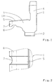
- the proposed coupling body 1 has an annular base body 3, to which an outer cone 4 with a friction surface 19 is formed.
- the friction surface 19 of the outer cone 4 has a plurality of axially extending flats 5.
- an annular ⁇ lfangnut 6 is provided for collecting the oil provided by the shaft through corresponding holes.
- 4 recesses 7 are provided on the front side of the outer cone in the radial direction. The recesses 7 are arranged distributed as radial cutouts over the circumference, as is made Fig. 2 is seen.
- the front-side recesses 7 connect the ⁇ lfangnut 6 with the flats 5, so that the oil collected in the ⁇ lfangnut 6 due to the centrifugal force on the recesses 7 can get into the flats 5.
- the oil can then wet the entire friction surface 19 of the outer cone 4.
- This embodiment can be used primarily in synchronization devices in which the coupling body 1 has a friction surface 19 made of steel and the synchronizer ring 8 is provided with a friction lining 9 consisting of molybdenum.
- the synchronizer ring 8 comprises an annular base body 10, to which an inner cone 11 is formed, on the surface of a friction lining 9 is applied, wherein in 3 and 4 only the friction lining 9 of the synchronizer ring 8 is shown.
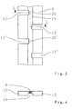
- Fig. 3 shows the unrolled in the plane friction lining 9 of the synchronizer ring. 8
- the friction lining 9 is designed annular and has at each edge region a plurality of axially extending grooves 12, 12 'and 13, 13'. Both the grooves 12, 12 'and the grooves 13, 13' have a length which is dimensioned such that the grooves 12, 12 'and 13, 13' cut an annular groove 14 arranged centrally on the friction lining 9.
- the outlet 20, 20 'of each groove 12, 12' can, as in Fig. 3 indicated by dashed line, have in longitudinal section an arc shape with a predetermined radius. There are other forms possible.
- each groove 12, 12 'and 13, 13' is dimensioned so that it corresponds approximately to the thickness of the friction lining 9. Furthermore, the grooves 12, 12 'are each offset from the grooves 13, 13' at the opposite edge of the friction lining 9.
- the oil in each case in the frontally disposed grooves 12, 12 'penetrate, to then be tangentially transported in the annular groove 14 and finally by the grooves 13, 13' exit again. Due to the tangential relative movement of the coupling body 1 relative to the friction lining 9 of the synchronizer ring 8, the friction surfaces are wetted and cooled during the synchronization process.
- the annular groove 14 with the connected grooves 12, 12 'and 13, 13' allows an oil purging and thus improved heat dissipation at the friction surfaces of the synchronizer ring 8 and the coupling body. 1
- FIGS. 5 and 6 a second embodiment of the synchronizer ring 8 is shown.
- two adjacent grooves 12 and 12 'or 13 and 13' are arranged mirror-symmetrically to each other.
- the volume flow through the grooves 12, 12 'and 13, 13' is increased and as a result the cooling is further improved.
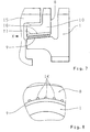
- FIGS. 7 and 8 a third embodiment of the synchronizer ring 8 is shown, wherein Fig. 7 a partial view of a possible synchronization device with the synchronizer ring 8, the coupling body 1 and a synchronizer body 15 shows.
- the synchronizer ring 8 has a plurality of axial grooves 16 on its inner cone 11. The axial grooves 16 are arranged distributed over the circumference of the inner cone 11 at a predetermined distance from one another.
- the axial grooves 16 are provided above the friction lining 9. This is both off Fig. 7 as well as Fig. 8 seen.
- the axial grooves 16 can be produced by a suitable pressing method prior to the application of the friction lining 9.
- the friction lining 9 is thus only on web areas between the axial grooves 16, as in particular from Fig. 8 is apparent.
- the axial grooves 16 are z. B. supplied with oil from the ⁇ lfangnut 6 of the coupling body 1, not shown. In this way, the oil can enter the end faces in the axial grooves 16 and then flow through the axial grooves 16. As a result, the friction lining 9 is cooled and the resulting heat dissipated by the oil.
- the axial grooves 16 have a conical shape, so that due to the centrifugal force, a pump effect is effected in the axial grooves 16, which further increases the volume flow of the oil and thus enhances the cooling effect.
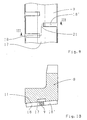
- FIGS. 9 and 10 is a fourth, inventive embodiment of the synchronizer ring 8 is shown.
- the inner cone 11 of the synchronizer ring 8 has an annular groove 17, which is arranged approximately centrally on the surface of the inner cone 11.
- the annular groove 17 is at least cut by the axially extending in the friction lining 9 grooves 18, 18 '. In this way, oil can pass from the frontal groove 18 in the annular groove 17 to then be able to escape through the inside groove 18 'from the friction dressing again. Consequently, optimal cooling of the friction lining 9 of the synchronizer ring 8 is ensured even in this embodiment.
Landscapes
- Engineering & Computer Science (AREA)
- General Engineering & Computer Science (AREA)
- Mechanical Engineering (AREA)
- Mechanical Operated Clutches (AREA)
Description
- Die vorliegende Erfindung betrifft einen Synchronring und eine Synchronisierungseinrichtung gemäß der jeweils im Oberbegriff des Patentanspruches 1 bzw. 9 näher definierten Art.
- Aus der Fahrzeugtechnik sind Synchronisierungseinrichtungen zum Synchronisieren von Losrädern an einer Welle eines Fahrzeuggetriebes bekannt. Üblicherweise umfasst die Synchronisierungseinrichtung zumindest einen Synchronring und wenigstens einen Kupplungskörper. Der Kupplungskörper ist formschlüssig mit dem zu synchronisierenden Losrad verbunden. Der Synchronring ist formschlüssig mit einer Schaltmuffe verbindbar, welche wiederum über einen Synchronkörper drehfest mit der Welle des Fahrzeuggetriebes verbunden ist. Zum Synchronisieren des Losrades wird der Synchronring mit dem Kupplungskörper reibschlüssig verbunden.
- Die während der Synchronisierung aneinander reibenden Reibflächen des Synchronringes und des Kupplungskörpers werden durch die entstehende Reibung erwärmt, so dass eine Kühlung der jeweiligen Reibflächen an dem Synchronring und dem Kupplungskörper erforderlich ist.
- Es ist auch bekannt, dass bei Synchronisierungseinrichtungen in so genannten Rangegetrieben an dem Außenkonus des ringförmigen Kupplungskörpers eine radial innen umlaufende Ringnut zum Auffangen des über radiale Bohrungen der Welle transportierte Kühl- und Schmieröl vorgesehen ist. Während der Synchronphase sind die Reibfläche des Außenkonus des Kupplungskörpers und die Reibfläche eines Innenkonus des Synchronringes aufeinander gepresst. Somit wird verhindert, dass das Öl zur Kühlung an die Reibflächen des Synchronringes und des Kupplungskörpers gelangt.
- Um die jeweiligen Reibflächen auch während der Synchronphase mit Öl zu versorgen, sind bei der bekannten Synchronisierungseinrichtung radiale Bohrungen an dem Außenkonus des Kupplungskörpers vorgesehen, welche das aus der umlaufenden Ringnut vorhandene Öl zur Oberfläche des Außenkonus des Kupplungskörpers transportieren. Die Oberfläche des Außenkonus weist axial verlaufende Nuten zur Ölverteilung auf. Auf diese Weise können die miteinander in Kontakt stehenden Reibflächen des Synchronringes und des Kupplungskörpers mit Kühlöl versorgt werden.
- Es hat sich jedoch gezeigt, dass durch die an der Stirnseite des Außenkonus radial verlaufenden Bohrungen eine mechanische Schwächung dieses Stirnbereiches des Außenkonus des Kupplungskörpers auftritt. Somit besteht die Gefahr, dass aufgrund von Wärmespannungen Risse an dem Außenkonus des Kupplungskörpers auftreten.
- Aus der Druckschrift
DE 34 17 813 C1 ist die Verwendung von Streusinter-Reibbelägen bei Synchronringen oder Gleichlaufringen von Synchronisierungseinrichtungen bekannt. Diese Reibbeläge können in axialer Richtung Drainagenuten zur Ölverdrängung während der Herstellung des Reibschlusses zwischen den entsprechenden Bauteilen aufweisen. Die DruckschriftDE 27 44 994 C2 beschreibt ein Herstellungsverfahren für einen Synchronring, der in seinem Reibbelag ebenfalls in axialer Richtung verlaufende Nuten zum Öltransport aufweist. - Darüber hinaus ist aus der Druckschrift
DE 20 55 345 eine Synchronisierung für Schaltgetriebe bekannt. Der Synchronring der offenbarten Synchronisierungseinrichtung weist axial verlaufende Vertiefungen auf, in denen der Reibbelag eingepasst ist, so dass axial verlaufende Mulden in dem Reibbelag des Synchronringes vorgesehen sind. - Schließlich offenbart die Druckschrift
EP 0 122 562 B1 einen Synchronring für ein Fahrzeuggetriebe, bei dem der Reibbelag des Innenkonus des Synchronringes Axialnuten aufweist. Zusätzlich sind an dem Reibbelag Umfangsrillen vorgesehen. - Der vorliegenden Erfindung liegt die Aufgabe zugrunde, einen Synchronring für eine Synchronisierungseinrichtung vorzuschlagen, welche eine verbesserte Kühlung während der Synchronisierungsphase realisieren.
- Diese Aufgabe wird hinsichtlich des Synchronringes durch die Merkmale des Patentanspruches 1 und bezüglich der Synchronisierungseinrichtung durch die Merkmale des Patentanspruches 9 gelöst. Vorteilhafte Ausgestaltungen ergeben sich insbesondere aus den jeweiligen Unteransprüchen.
- Die der Erfindung zugrunde liegende Aufgabe wird durch einen Synchronring einer Synchronisierungseinrichtung mit einem ringförmigen Grundkörper gelöst, an dem ein Innenkonus angeformt ist, an dem eine Reibfläche vorgesehen ist, wobei der Innenkonus zumindest eine Ringnut oder dergleichen aufweist und wobei der ringförmige Reibbelag an jedem Rand mehrere über den Umfang verteilt angeordnete axiale Nuten aufweist, die jeweils mit der Ringnut strömungsmäßig verbunden sind.
- Vorzugsweise kann vor dem Aufbringen des Reibbelages auf den Synchronring eine Ringnut in die Oberfläche des Synchronringes bzw. in den Innenkonus eingebracht werden. Dabei ist es wichtig, dass die Länge der axialen Nuten in dem Reibbelag so bemessen ist, dass die Ringnut zumindest mit den Axialnuten strömungsmäßig verbunden ist. Auf diese Weise wird sichergestellt, dass das Öl von der einen Seite durch die Axialnut eindringen und durch die als Kanal ausgebildete Ringnut in die zum anderen Rand des Reibbelages führenden Axialnut transportiert wird.
- Vorzugsweise kann die Ringnut mittig an dem Innenkonus verlaufen. Wie auch schon bei den vorhergehenden Ausgestaltungen des Synchronringes können die axialen Nuten an jedem Rand der Reibfläche bevorzugt zueinander versetzt angeordnet sein.
- Unabhängig von der Ausführungsform des Synchronringes kann die Tiefe jeder axialen Nut etwa der Dicke des Reibbelages entsprechen. Es sind auch andere Ausführungen denkbar. Des Weiteren kann die Länge jeder Nut so bemessen sein, dass die Ringnut des Synchronringes von der Nut zumindest angeschnitten wird. Auf diese Weise ist eine strömungsmäßige Verbindung zwischen jeder Axialnut und der Ringnut gewährleistet. Es sind auch andere konstruktive Ausführungen der Nuten denkbar, um eine Verbindung mit der Ringnut zu schaffen.
- Ebenfalls unabhängig von den vorgeschlagenen Ausführungsvarianten des Synchronringes kann z. B. ein organischer Werkstoff als Reibbelag für den Synchronring vorgesehen sein. Vorzugsweise kann Karbon oder dergleichen als Werkstoff verwendet werden. Diese Wahl des Werkstoffes für den Reibbelag bietet den Vorteil, dass auf einfachste Weise Profilierungen an dem Reibbelag vorgenommen werden können.
- Schließlich wird die der Erfindung zugrunde liegende Aufgabe auch durch eine Synchronisierungseinrichtung zum Synchronisieren von Lösrädern eines Fahrzeuggetriebes gelöst, mit zumindest einem Synchronring und einem zugeordneten Kupplungskörper, wobei die erfindungsgemäße Synchronisierungseinrichtung zumindest den vorgeschlagenen Synchronring umfasst. Somit wird durch die vorliegende Erfindung nicht nur ein vorgeschlagener Synchronring separat beansprucht, sondern auch die gesamte Synchronisierungseinrichtung, die insbesondere die vorgeschlagenen Bauteile verwendet. Auf diese Weise wird die Lebensdauer der Synchronisierungseinrichtung und der dazugehörigen Bauteile erhöht.
- Beispielsweise können die vorgeschlagenen Ausführungsformen auch mit bereits bekannten Ausführungen kombiniert werden. Es ist auch denkbar, dass die Profilierungen insbesondere an dem Reibbelag durch zueinander beabstandete Einzelelemente realisiert werden, die dann zusammen den Reibbelag bilden.
- Nachfolgend wird die vorliegende Erfindung anhand der Zeichnungen näher erläutert.
- Es zeigen:
- Fig. 1
- eine Ansicht einer möglichen Ausführungsform eines Kupplungskörpers für eine Synchronisierungseinrich- tung mit stirnseitigen Ausnehmungen;
- Fig. 2
- eine Draufsicht auf den Kupplungskörper gemäß
Fig. 1 ; - Fig. 3
- eine Draufsicht auf einen in die Ebene abgerollten Reibbelag ei- nes Synchronringes für eine Synchronisie- rungseinrichtung;
- Fig. 4
- eine quer geschnittene Ansicht des Reibbelages entlang der Schnittlinie I-I gemäß
Fig. 3 ; - Fig. 5
- eine Draufsicht auf einen in die Ebene abgerollten Reibbelag ei- ner zweiten Ausführungsform des Synchronringes;
- Fig. 6
- eine quer geschnittene Ansicht des Reibbelages entlang der Schnittlinie II-II gemäß
Fig. 5 ; - Fig. 7
- eine Teilansicht einer Synchronisierungseinrichtung mit einem Synchronring gemäß einer dritten Ausführungsform;
- Fig. 8
- eine seitliche Teilansicht des Synchronringes und des Kupplungs- körpers gemäß
Fig. 7 ; - Fig. 9
- eine Draufsicht auf einen in die Ebene abgerollten Reibbelag ei- ner vierten erfindungsgemäßen Ausführungsform des Synchronringes und
- Fig. 10
- eine quer geschnittene Ansicht des Synchronringes entlang der Schnittlinie III-III gemäß
Fig. 9 . - In den
Fig. 1 und 2 ist eine mögliche Ausführungsform eines Kupplungskörpers für eine Synchronisierungseinrichtung gezeigt, wobei dieFig. 3 bis 10 verschiedene Ausführungsformen eines Synchronringes für eine Synchronisierungseinrichtung darstellen. - Die nur teilweise in
Fig. 7 angedeutete Synchronisierungseinrichtung wird üblicherweise zum Synchronisieren von Losrädern an einer Welle eines Fahrzeuggetriebes verwendet und umfasst zumindest einen Synchronring 8 und wenigstens einen Kupplungskörper 1. Der Kupplungskörper 1 ist formschlüssig über eine Verzahnung 2 mit dem nicht weiter dargestellten Losrad der Welle, welches synchronisiert werden soll, verbunden. Der Synchronring 8 ist, unabhängig von seiner gewählten Ausführungsform, formschlüssig mit einer Schaltmuffe verbindbar, welche wiederum über einen Synchronkörper 15 drehfest mit der Welle des Fahrzeuggetriebes verbunden ist. Zum Synchronisieren des Losrades wird der Synchronring 8 mit dem Kupplungskörper 1 über die jeweiligen Reibflächen reibschlüssig verbunden. - Um die an den Reibflächen des Synchronringes 8 und des Kupplungskörpers 1 entstehende Wärme abzuführen und somit eine ausreichende Kühlung sicherzustellen, werden die Reibflächen mit einem Kühlmittel, wie z. B. Öl, beaufschlagt.
- Der vorgeschlagene Kupplungskörper 1 weist einen ringförmigen Grundkörper 3 auf, an den ein Außenkonus 4 mit einer Reibfläche 19 angeformt ist. Die Reibfläche 19 des Außenkonus 4 weist mehrere axial verlaufende Abflachungen 5 auf. Radial innen an dem Außenkonus 4 ist eine ringförmige Ölfangnut 6 zum Auffangen des von der Welle durch entsprechende Bohrungen bereitgestellten Öls vorgesehen. Um das in der Ölfangnut 6 gesammelte bzw. aufgefangene Öl zur Reibfläche 19 des Außenkonus 4 des Kupplungskörpers 1 zu transportieren, sind stirnseitig an dem Außenkonus 4 Ausnehmungen 7 in radialer Richtung vorgesehen. Die Ausnehmungen 7 sind als radiale Ausfräsungen über den Umfang verteilt angeordnet, wie dies aus
Fig. 2 ersichtlicht ist. - Die stirnseitigen Ausnehmungen 7 verbinden die Ölfangnut 6 mit den Abflachungen 5, so dass das in der Ölfangnut 6 gesammelte Öl aufgrund der Zentrifugalkraft über die Ausnehmungen 7 in die Abflachungen 5 gelangen kann. Durch die axial verlaufenden Abflachungen 5 kann das Öl dann die gesamte Reibfläche 19 des Außenkonus 4 benetzen.
- Diese Ausgestaltung kann vornehmlich bei Synchronisierungseinrichtungen verwendet werden, bei denen der Kupplungskörper 1 eine Reibfläche 19 aus Stahl aufweist und der Synchronring 8 mit einem aus Molybdän bestehenden Reibbelag 9 versehen ist.
- In den
Fig. 3 und 4 ist eine mögliche erste Ausführungsform eines Synchronringes 8 für eine Synchronisierungseinrichtung dargestellt. Der Synchronring 8 umfasst einen ringförmigen Grundkörper 10, an den ein Innenkonus 11 angeformt ist, auf dessen Oberfläche ein Reibbelag 9 aufgebracht ist, wobei inFig. 3 und 4 lediglich der Reibbelag 9 des Synchronringes 8 dargestellt ist.Fig. 3 zeigt den in die Ebene abgerollten Reibbelag 9 des Synchronringes 8. - Bei dieser Ausführungsform ist der Reibbelag 9 ringförmig ausgeführt und weist an jedem Randbereich mehrere axial verlaufende Nuten 12, 12' und 13, 13' auf. Sowohl die Nuten 12, 12' als auch die Nuten 13, 13' weisen eine Länge auf, die so bemessen ist, dass die Nuten 12, 12' und 13, 13' eine mittig auf dem Reibbelag 9 angeordnete Ringnut 14 anschneiden. Der Auslauf 20, 20' jeder Nut 12, 12' kann, wie in
Fig. 3 mittels gestrichelter Linie angedeutet, im Längsschnitt eine Bogenform mit vorbestimmtem Radius aufweisen. Es sind auch andere Formen möglich. - Wie insbesondere aus
Fig. 4 ersichtlich ist, wird die Tiefe jeder Nut 12, 12' und 13, 13' so bemessen, dass sie etwa der Dicke des Reibbelages 9 entspricht. Ferner sind die Nuten 12, 12' jeweils zu den Nuten 13, 13' an dem gegenüberliegenden Rand des Reibbelages 9 versetzt angeordnet. Bei dieser Profilierungsvariante des Reibbelages 9 des Synchronringes 8 kann das Öl jeweils in die stirnseitig angeordneten Nuten 12, 12' eindringen, um dann in der Ringnut 14 tangential transportiert zu werden und um schließlich durch die Nuten 13, 13' wieder auszutreten. Durch die tangentiale Relativbewegung des Kupplungskörpers 1 relativ zum Reibbelag 9 des Synchronringes 8 werden die Reibflächen während des Synchronvorganges benetzt und gekühlt. Somit ermöglicht die Ringnut 14 mit den angeschlossenen Nuten 12, 12' und 13, 13' eine Öldurchspülung und damit einen verbesserten Wärmeabtransport an den Reibflächen des Synchronringes 8 und des Kupplungskörpers 1. - In den
Fig. 5 und 6 ist eine zweite Ausführungsvariante des Synchronringes 8 dargestellt. Bei dieser Ausführungsvariante weist der Reibbelag 9 im Gegensatz zur ersten Ausführungsform gemäß derFig. 3 und 4 jeweils an den Rändern des Reibbelages 9 schräg verlaufende Nuten 12, 12' und 13, 13' auf. Dabei sind jeweils zwei benachbarte Nuten 12 und 12' bzw. 13 und 13' spiegelsymmetrisch zueinander angeordnet. Bei dieser weiteren Profilierungsvariante ergibt sich der Vorteil, dass durch die schräg verlaufenden Nuten 12, 12' und 13, 13' unabhängig von der Drehrichtung des Synchronringes 8 das Öl in die Nuten 12, 12' und 13, 13' quasi hineingeschaufelt wird. Durch diesen Fördereffekt wird der Volumenstrom durch die Nuten 12, 12' und 13, 13' vergrößert und infolgedessen die Kühlung weiter verbessert. - In den
Fig. 7 und 8 ist eine dritte Ausführungsform des Synchronringes 8 dargestellt, wobeiFig. 7 eine Teilansicht einer möglichen Synchronisierungseinrichtung mit dem Synchronring 8, dem Kupplungskörper 1 und einem Synchronkörper 15 zeigt. Bei dieser Ausführungsvariante ist vorgesehen, dass der Synchronring 8 an seinem Innenkonus 11 mehrere Axialnuten 16 aufweist. Die Axialnuten 16 sind über den Umfang des Innenkonus 11 in einem vorbestimmten Abstand zueinander verteilt angeordnet. - Die Axialnuten 16 sind oberhalb des Reibbelages 9 vorgesehen. Dies ist sowohl aus
Fig. 7 als auchFig. 8 ersichtlich. Die Axialnuten 16 können durch ein geeignetes Pressverfahren vor dem Aufbringen des Reibbelages 9 hergestellt werden. Der Reibbelag 9 liegt somit nur auf Stegbereichen zwischen den Axialnuten 16 auf, wie insbesondere ausFig. 8 ersichtlich ist. Dadurch besteht die Möglichkeit, dass der Reibbelag 9 durch die Axialnuten 16 gekühlt wird. Die Axialnuten 16 werden z. B. mit Öl aus der nicht weiter dargestellten Ölfangnut 6 des Kupplungskörpers 1 versorgt. Auf diese Weise kann das Öl stirnseitig in die Axialnuten 16 eintreten und dann die Axialnuten 16 durchströmen. Dadurch wird der Reibbelag 9 gekühlt und die entstehende Wärme durch das Öl abgeführt. - Bevorzugt weisen die Axialnuten 16 einen konischen Verlauf auf, so dass aufgrund der Zentrifugalkraft ein Pumpeneffekt in den Axialnuten 16 bewirkt wird, der den Volumenstrom des Öls weiter erhöht und somit den Kühleffekt verstärkt.
- In den
Fig. 9 und 10 ist eine vierte, erfindungsgemäße Ausführungsvariante des Synchronringes 8 dargestellt. Bei dieser Profilierungsvariante weist der Innenkonus 11 des Synchronringes 8 eine Ringnut 17 auf, welche etwa mittig an der Oberfläche des Innenkonus 11 angeordnet ist. Die Ringnut 17 wird von den axial im Reibbelag 9 verlaufenden Nuten 18, 18' zumindest angeschnitten. Auf diese Weise kann Öl von der stirnseitigen Nut 18 in die Ringnut 17 gelangen, um dann durch die innenseitige Nut 18' aus dem Reibverband wieder austreten zu können. Folglich wird auch bei dieser Ausführungsvariante eine optimale Kühlung des Reibbelages 9 des Synchronringes 8 gewährleistet. -
- 1
- Kupplungskörper
- 2
- Verzahnung
- 3
- Grundkörper des Kupplungskörpers
- 4
- Außenkonus
- 5
- Abflachung
- 6
- Ölfangnut
- 7
- Ausnehmung
- 8
- Synchronring
- 9
- Reibbelag des Synchronringes
- 10
- Grundkörper des Synchronringes
- 11
- Innenkonus
- 12, 12'
- axial verlaufende Nut
- 13, 13'
- axial verlaufende Nut
- 14
- Ringnut an dem Reibbelag
- 15
- Synchronkörper
- 16
- Axialnut
- 17
- Ringnut an dem Innenkonus
- 18, 18'
- Nut
- 19
- Reibfläche des Kupplungskörpers
- 20, 20'
- Auslauf der Nut
- 21
- Auslauf der Nut
Claims (9)
- Synchronring einer Synchronisierungseinrichtung, mit einem ringförmigen Grundkörper (10), an dem ein Innenkonus (11) angeformt ist, an dem ein Reibbelag (9) vorgesehen ist, dadurch gekennzeichnet, dass der Innenkonus (11) zumindest eine Ringnut (17) aufweist, und dass der ringförmige Reibbelag (9) an jedem Rand mehrere über den Umfang verteilt angeordnete axiale Nuten (18, 18') aufweist, die jeweils mit der Ringnut (17) strömungsmäßig verbunden sind.
- Synchronring nach Anspruch 1, dadurch gekennzeichnet, dass die Ringnut (17) etwa mittig an der Oberfläche des Innenkonus (11) verläuft.
- Synchronring nach Anspruch 1 oder 2, dadurch gekennzeichnet, dass die jeweils an den Rändern des Reibbelages (9) beginnenden Nuten (18, 18') zueinander versetzt angeordnet sind.
- Synchronring nach einem der Ansprüche 1 bis 3, dadurch gekennzeichnet, dass die Tiefe jeder Nut (18, 18') etwa der Dicke des Reibbelages (9) entspricht.
- Synchronring nach einem der Ansprüche 1 bis 4, dadurch gekennzeichnet, dass der Auflauf (21) jeder Nut (18, 18') im Längsschnitt etwa bogenförmig ist.
- Synchronring nach einem der Ansprüche 1 bis 5, dadurch gekennzeichnet, dass die Länge jeder Nut (18, 18') so bemessen ist, dass die Nut (18, 18') die Ringnut (17) anschneidet.
- Synchronring nach einem der Ansprüche 1 bis 6, dadurch gekennzeichnet, dass ein organischer Werkstoff als Reibbelag (9) des Synchronringes (8) vorgesehen ist.
- Synchronring nach Anspruch 7, dadurch gekennzeichnet, dass Karbon als Werkstoff für den Reibbelag (9) vorgesehen ist.
- Synchronisierungseinrichtung zum Synchronisieren von Losrädem an einer Welle eines Fahrzeuggetriebes, mit zumindest einem Synchronring (8) nach einem der vorangehenden Ansprüche und einem zugeordneten Kupplungskörper (1).
Applications Claiming Priority (2)
| Application Number | Priority Date | Filing Date | Title |
|---|---|---|---|
| DE102007010764A DE102007010764A1 (de) | 2007-03-06 | 2007-03-06 | Kupplungskörper und Synchronring für eine Synchronisierungseinrichtung |
| PCT/EP2008/052138 WO2008107315A2 (de) | 2007-03-06 | 2008-02-21 | Kupplungskörper und synchronring für eine synchronisierungseinrichtung |
Publications (2)
| Publication Number | Publication Date |
|---|---|
| EP2118508A2 EP2118508A2 (de) | 2009-11-18 |
| EP2118508B1 true EP2118508B1 (de) | 2011-08-17 |
Family
ID=39345479
Family Applications (1)
| Application Number | Title | Priority Date | Filing Date |
|---|---|---|---|
| EP08709168A Not-in-force EP2118508B1 (de) | 2007-03-06 | 2008-02-21 | Synchronring für eine synchronisierungseinrichtung |
Country Status (6)
| Country | Link |
|---|---|
| EP (1) | EP2118508B1 (de) |
| JP (1) | JP5283637B2 (de) |
| CN (1) | CN101622466B (de) |
| AT (1) | ATE520890T1 (de) |
| DE (1) | DE102007010764A1 (de) |
| WO (1) | WO2008107315A2 (de) |
Families Citing this family (15)
| Publication number | Priority date | Publication date | Assignee | Title |
|---|---|---|---|---|
| DE102008046916B4 (de) * | 2008-09-12 | 2020-03-12 | Volkswagen Ag | Synchronisiereinrichtung für ein Kraftfahrzeug |
| DE102011103344A1 (de) * | 2011-05-27 | 2012-11-29 | PMG Füssen GmbH | Verfahren zur herstellung eines bauteiles mit einem reibbelag |
| DE102011120343B4 (de) * | 2011-11-30 | 2016-03-31 | Getrag Getriebe- Und Zahnradfabrik Hermann Hagenmeyer Gmbh & Cie Kg | Verfahren zur Herstellung eines Kupplungskörpers sowie Kupplungskörper für eine Synchronisiereinrichtung |
| CN102425619B (zh) * | 2012-01-01 | 2013-03-27 | 赵孝民 | 一种同步锥毂 |
| DE102012221716B4 (de) * | 2012-11-28 | 2024-08-22 | Schaeffler Technologies AG & Co. KG | Synchronisiereinrichtung eines Kraftfahrzeug-Zahnräderwechselgetriebes |
| CN205780434U (zh) * | 2013-07-04 | 2016-12-07 | 舍弗勒技术股份两合公司 | 自调节式离合器分离轴承 |
| DE102013215617C5 (de) | 2013-08-08 | 2018-07-19 | Schaeffler Technologies AG & Co. KG | Kupplungskörper einer Synchronisiervorrichtung |
| DE102015212043A1 (de) | 2015-06-29 | 2016-12-29 | Zf Friedrichshafen Ag | Verfahren und Vorrichtung zum Fügen einer Welle-Nabe-Verbindung |
| DE102015214017A1 (de) | 2015-07-24 | 2017-01-26 | Zf Friedrichshafen Ag | Verfahren und Vorrichtung zur Bestimmung eines Verschleißzustands eines Synchronrings sowie landwirtschaftliche Arbeitsmaschine |
| DE102016113422A1 (de) | 2016-07-20 | 2018-01-25 | Getrag Getriebe- Und Zahnradfabrik Hermann Hagenmeyer Gmbh & Cie Kg | Reibring und Mehrfachkegel-Synchronschaltkupplung |
| CN106224401A (zh) * | 2016-08-31 | 2016-12-14 | 重庆铁马工业集团有限公司 | 一种同步器锥体增加锥面润滑方法 |
| EP3473879B1 (de) * | 2017-10-17 | 2020-09-30 | Ningbo Geely Automobile Research & Development Co. Ltd. | Synchronring |
| EP3708860B1 (de) | 2019-03-13 | 2021-08-04 | Ningbo Geely Automobile Research & Development Co. Ltd. | Synchronisierungsring |
| EP3748184B1 (de) * | 2019-06-05 | 2023-01-25 | Ningbo Geely Automobile Research & Development Co., Ltd. | Synchronisierungsring |
| KR102731557B1 (ko) * | 2019-09-16 | 2024-11-18 | 현대자동차주식회사 | 차량용 콘 클러치 |
Family Cites Families (26)
| Publication number | Priority date | Publication date | Assignee | Title |
|---|---|---|---|---|
| DE2008945A1 (de) * | 1969-04-08 | 1970-11-05 | Ford-Werke AG, 5000 Köln-Deutz | Zahnradeinheit für Getriebe, insbesondere for Kraftfahrzeuge |
| DE2055345A1 (de) | 1970-11-11 | 1972-05-18 | Zahnradfabrik Friedrichshafen | Synchronisierring in Schaltgetrieben |
| JPS536753Y2 (de) * | 1973-05-09 | 1978-02-21 | ||
| JPS5139152U (de) * | 1974-09-19 | 1976-03-24 | ||
| DE2744994C2 (de) | 1977-10-06 | 1985-08-29 | Stieber Division Der Borg-Warner Gmbh, 6900 Heidelberg | Verfahren zur Herstellung eines Synchronosierringes |
| DE3113650C2 (de) * | 1981-04-04 | 1989-02-02 | Klöckner-Humboldt-Deutz AG, 5000 Köln | Synchronisiereinrichtung, insbesondere für das Wechselgetriebe eines Kraftfahrzeugs |
| JPS59187114A (ja) | 1983-04-06 | 1984-10-24 | Kyowa Gokin Kk | 車輛変速機における同期リング |
| DE3417813C1 (de) | 1984-05-14 | 1985-06-05 | Sinterstahl GmbH, 8958 Füssen | Verwendung von Streusinter-Reibbelaegen in Reibkupplungen oder -bremsen |
| US4878282A (en) * | 1987-09-04 | 1989-11-07 | Borg-Warner Automotive Gmbh | Method for the production of friction plates, synchronizing blocker rings or similar structures |
| JPH0171228U (de) * | 1987-10-31 | 1989-05-12 | ||
| JPH0241723U (de) * | 1988-09-14 | 1990-03-22 | ||
| DE4017142A1 (de) * | 1990-05-28 | 1991-12-05 | Kloeckner Humboldt Deutz Ag | Synchronisiereinrichtung fuer zahnradwechselgetriebe |
| JP2605890Y2 (ja) * | 1993-05-13 | 2000-08-21 | 日産ディーゼル工業株式会社 | 変速機の同期装置 |
| JP3781811B2 (ja) * | 1995-09-22 | 2006-05-31 | Gkn ドライブライン トルクテクノロジー株式会社 | 差動制限装置 |
| JPH09119504A (ja) * | 1995-10-26 | 1997-05-06 | Nsk Warner Kk | トルクコンバータに用いるロックアップクラッチ |
| JPH09144773A (ja) * | 1995-11-20 | 1997-06-03 | Kinousei Mokushitsu Shinsozai Gijutsu Kenkyu Kumiai | ウッドセラミックスからなる摩擦材の層を具えたシンクロナイザーリング |
| JPH11190362A (ja) * | 1997-12-26 | 1999-07-13 | Nippon Piston Ring Co Ltd | シンクロナイザリング |
| FR2789143B1 (fr) * | 1999-01-29 | 2001-03-02 | Valeo | Dispositif mettant en oeuvre un frottement en milieu liquide et comportant une garniture de frottement a porosite controlee |
| DE10036087B4 (de) * | 2000-07-25 | 2009-10-01 | Schaeffler Kg | Gangrad mit einem Kupplungskörper |
| JP2002235772A (ja) * | 2001-02-13 | 2002-08-23 | Kyowa Metal Work Co Ltd | 円錐クラッチの摩擦材貼付方法 |
| JP2002242954A (ja) * | 2001-02-14 | 2002-08-28 | Aisin Aw Co Ltd | 摩擦板 |
| WO2004111479A1 (ja) * | 2003-06-10 | 2004-12-23 | Oiles Corporation | シンクロナイザリング |
| EP1668269B1 (de) * | 2003-10-02 | 2009-02-11 | Sulzer Friction Systems (Germany) GmbH | Reibmaterialbelag und verfahren zur bereitstellung solch eines reibmaterialbelags |
| AT502647B1 (de) * | 2004-01-15 | 2007-05-15 | Miba Sinter Austria Gmbh | Synchronisierring für ein zahnradwechselgetriebe |
| JP2006009953A (ja) * | 2004-06-25 | 2006-01-12 | Nissan Diesel Motor Co Ltd | 変速機の同期装置 |
| JP4593983B2 (ja) * | 2004-06-25 | 2010-12-08 | Udトラックス株式会社 | 変速機の同期装置 |
-
2007
- 2007-03-06 DE DE102007010764A patent/DE102007010764A1/de not_active Withdrawn
-
2008
- 2008-02-21 WO PCT/EP2008/052138 patent/WO2008107315A2/de not_active Ceased
- 2008-02-21 AT AT08709168T patent/ATE520890T1/de active
- 2008-02-21 CN CN2008800068026A patent/CN101622466B/zh not_active Expired - Fee Related
- 2008-02-21 JP JP2009552159A patent/JP5283637B2/ja not_active Expired - Fee Related
- 2008-02-21 EP EP08709168A patent/EP2118508B1/de not_active Not-in-force
Also Published As
| Publication number | Publication date |
|---|---|
| JP2010520429A (ja) | 2010-06-10 |
| ATE520890T1 (de) | 2011-09-15 |
| JP5283637B2 (ja) | 2013-09-04 |
| CN101622466B (zh) | 2011-10-12 |
| CN101622466A (zh) | 2010-01-06 |
| EP2118508A2 (de) | 2009-11-18 |
| WO2008107315A2 (de) | 2008-09-12 |
| WO2008107315A3 (de) | 2008-12-18 |
| DE102007010764A1 (de) | 2008-09-11 |
Similar Documents
| Publication | Publication Date | Title |
|---|---|---|
| EP2118508B1 (de) | Synchronring für eine synchronisierungseinrichtung | |
| EP3250836B1 (de) | Gleitlageranordnung eines drehelements auf einem lagerbolzen, insbesondere eines planetenrades auf einem planetenradbolzen eines planetenradgetriebes | |
| DE102007044856B4 (de) | Kupplungsanordnung mit einer Kupplungsscheibe mit inneren Fluidkanälen | |
| EP3273085B1 (de) | Reibring und mehrfachkegel-synchronschaltkupplung | |
| EP0521843B1 (de) | Reibring | |
| AT516124A1 (de) | Reiblamelle | |
| EP1464858A2 (de) | Kupplungsanordnung | |
| EP2028386A1 (de) | Synchronring für eine Synchronisierungseinrichtung, Reibbelag-Rohling, sowie Verfahren zur Herstellung eines Synchronrings | |
| EP3217031A1 (de) | Lamellenkupplung | |
| DE102008032458B4 (de) | Nasskupplung | |
| DE102010003077A1 (de) | Gleitlagerschale | |
| EP2994661B2 (de) | Kupplung mit reduziertem schleppmoment | |
| DE102010054253B4 (de) | Nasslaufende Kraftfahrzeugreibkupplung | |
| DE102011120343B4 (de) | Verfahren zur Herstellung eines Kupplungskörpers sowie Kupplungskörper für eine Synchronisiereinrichtung | |
| DE102006057112B4 (de) | Reibteil für eine reibschlüssig arbeitende Einrichtung und reibschlüssig arbeitende Einrichtung mit einem solchen Reibteil | |
| DE102016102701A1 (de) | Synchronisiervorrichtung und Synchronisationsverfahren | |
| DE102013222364B4 (de) | Reibungskupplung und Platte mit teilweise erhabenen Segmentfugen | |
| DE112013005659T5 (de) | Reibungsplatte mit verdichteten überlappenden Abschnitten | |
| EP3179124B1 (de) | Reiblamelle | |
| DE102009032180A1 (de) | Verfahren zum Herstellen einer Reiblamelle sowie Reiblamelle | |
| AT520443B1 (de) | Getriebe-Synchronisationseinrichtung | |
| EP3084250A1 (de) | Pulvermetallurgisch hergestellte komponente | |
| AT15554U1 (de) | Reiblamelle | |
| DE102013212281A1 (de) | Kupplungslamelle für eine nasslaufende Reibkupplung | |
| DE102012217103A1 (de) | Synchronring |
Legal Events
| Date | Code | Title | Description |
|---|---|---|---|
| PUAI | Public reference made under article 153(3) epc to a published international application that has entered the european phase |
Free format text: ORIGINAL CODE: 0009012 |
|
| 17P | Request for examination filed |
Effective date: 20090908 |
|
| AK | Designated contracting states |
Kind code of ref document: A2 Designated state(s): AT BE BG CH CY CZ DE DK EE ES FI FR GB GR HR HU IE IS IT LI LT LU LV MC MT NL NO PL PT RO SE SI SK TR |
|
| GRAP | Despatch of communication of intention to grant a patent |
Free format text: ORIGINAL CODE: EPIDOSNIGR1 |
|
| RTI1 | Title (correction) |
Free format text: SYNCHRONIZER RING FOR A SYNCHRONIZATION DEVICE |
|
| DAX | Request for extension of the european patent (deleted) | ||
| GRAS | Grant fee paid |
Free format text: ORIGINAL CODE: EPIDOSNIGR3 |
|
| GRAA | (expected) grant |
Free format text: ORIGINAL CODE: 0009210 |
|
| AK | Designated contracting states |
Kind code of ref document: B1 Designated state(s): AT BE BG CH CY CZ DE DK EE ES FI FR GB GR HR HU IE IS IT LI LT LU LV MC MT NL NO PL PT RO SE SI SK TR |
|
| REG | Reference to a national code |
Ref country code: GB Ref legal event code: FG4D Free format text: NOT ENGLISH |
|
| REG | Reference to a national code |
Ref country code: CH Ref legal event code: EP |
|
| REG | Reference to a national code |
Ref country code: IE Ref legal event code: FG4D Free format text: LANGUAGE OF EP DOCUMENT: GERMAN |
|
| REG | Reference to a national code |
Ref country code: SE Ref legal event code: TRGR |
|
| REG | Reference to a national code |
Ref country code: DE Ref legal event code: R096 Ref document number: 502008004522 Country of ref document: DE Effective date: 20111117 |
|
| REG | Reference to a national code |
Ref country code: NL Ref legal event code: VDEP Effective date: 20110817 |
|
| LTIE | Lt: invalidation of european patent or patent extension |
Effective date: 20110817 |
|
| PG25 | Lapsed in a contracting state [announced via postgrant information from national office to epo] |
Ref country code: LT Free format text: LAPSE BECAUSE OF FAILURE TO SUBMIT A TRANSLATION OF THE DESCRIPTION OR TO PAY THE FEE WITHIN THE PRESCRIBED TIME-LIMIT Effective date: 20110817 Ref country code: PT Free format text: LAPSE BECAUSE OF FAILURE TO SUBMIT A TRANSLATION OF THE DESCRIPTION OR TO PAY THE FEE WITHIN THE PRESCRIBED TIME-LIMIT Effective date: 20111219 Ref country code: NO Free format text: LAPSE BECAUSE OF FAILURE TO SUBMIT A TRANSLATION OF THE DESCRIPTION OR TO PAY THE FEE WITHIN THE PRESCRIBED TIME-LIMIT Effective date: 20111117 Ref country code: IS Free format text: LAPSE BECAUSE OF FAILURE TO SUBMIT A TRANSLATION OF THE DESCRIPTION OR TO PAY THE FEE WITHIN THE PRESCRIBED TIME-LIMIT Effective date: 20111217 Ref country code: NL Free format text: LAPSE BECAUSE OF FAILURE TO SUBMIT A TRANSLATION OF THE DESCRIPTION OR TO PAY THE FEE WITHIN THE PRESCRIBED TIME-LIMIT Effective date: 20110817 Ref country code: FI Free format text: LAPSE BECAUSE OF FAILURE TO SUBMIT A TRANSLATION OF THE DESCRIPTION OR TO PAY THE FEE WITHIN THE PRESCRIBED TIME-LIMIT Effective date: 20110817 |
|
| PG25 | Lapsed in a contracting state [announced via postgrant information from national office to epo] |
Ref country code: GR Free format text: LAPSE BECAUSE OF FAILURE TO SUBMIT A TRANSLATION OF THE DESCRIPTION OR TO PAY THE FEE WITHIN THE PRESCRIBED TIME-LIMIT Effective date: 20111118 Ref country code: LV Free format text: LAPSE BECAUSE OF FAILURE TO SUBMIT A TRANSLATION OF THE DESCRIPTION OR TO PAY THE FEE WITHIN THE PRESCRIBED TIME-LIMIT Effective date: 20110817 Ref country code: SI Free format text: LAPSE BECAUSE OF FAILURE TO SUBMIT A TRANSLATION OF THE DESCRIPTION OR TO PAY THE FEE WITHIN THE PRESCRIBED TIME-LIMIT Effective date: 20110817 Ref country code: CY Free format text: LAPSE BECAUSE OF FAILURE TO SUBMIT A TRANSLATION OF THE DESCRIPTION OR TO PAY THE FEE WITHIN THE PRESCRIBED TIME-LIMIT Effective date: 20110817 Ref country code: PL Free format text: LAPSE BECAUSE OF FAILURE TO SUBMIT A TRANSLATION OF THE DESCRIPTION OR TO PAY THE FEE WITHIN THE PRESCRIBED TIME-LIMIT Effective date: 20110817 |
|
| REG | Reference to a national code |
Ref country code: IE Ref legal event code: FD4D |
|
| PG25 | Lapsed in a contracting state [announced via postgrant information from national office to epo] |
Ref country code: CZ Free format text: LAPSE BECAUSE OF FAILURE TO SUBMIT A TRANSLATION OF THE DESCRIPTION OR TO PAY THE FEE WITHIN THE PRESCRIBED TIME-LIMIT Effective date: 20110817 Ref country code: IE Free format text: LAPSE BECAUSE OF FAILURE TO SUBMIT A TRANSLATION OF THE DESCRIPTION OR TO PAY THE FEE WITHIN THE PRESCRIBED TIME-LIMIT Effective date: 20110817 Ref country code: SK Free format text: LAPSE BECAUSE OF FAILURE TO SUBMIT A TRANSLATION OF THE DESCRIPTION OR TO PAY THE FEE WITHIN THE PRESCRIBED TIME-LIMIT Effective date: 20110817 |
|
| PG25 | Lapsed in a contracting state [announced via postgrant information from national office to epo] |
Ref country code: EE Free format text: LAPSE BECAUSE OF FAILURE TO SUBMIT A TRANSLATION OF THE DESCRIPTION OR TO PAY THE FEE WITHIN THE PRESCRIBED TIME-LIMIT Effective date: 20110817 Ref country code: RO Free format text: LAPSE BECAUSE OF FAILURE TO SUBMIT A TRANSLATION OF THE DESCRIPTION OR TO PAY THE FEE WITHIN THE PRESCRIBED TIME-LIMIT Effective date: 20110817 |
|
| PLBE | No opposition filed within time limit |
Free format text: ORIGINAL CODE: 0009261 |
|
| STAA | Information on the status of an ep patent application or granted ep patent |
Free format text: STATUS: NO OPPOSITION FILED WITHIN TIME LIMIT |
|
| PG25 | Lapsed in a contracting state [announced via postgrant information from national office to epo] |
Ref country code: DK Free format text: LAPSE BECAUSE OF FAILURE TO SUBMIT A TRANSLATION OF THE DESCRIPTION OR TO PAY THE FEE WITHIN THE PRESCRIBED TIME-LIMIT Effective date: 20110817 |
|
| PGFP | Annual fee paid to national office [announced via postgrant information from national office to epo] |
Ref country code: IT Payment date: 20120216 Year of fee payment: 5 |
|
| 26N | No opposition filed |
Effective date: 20120521 |
|
| PG25 | Lapsed in a contracting state [announced via postgrant information from national office to epo] |
Ref country code: HR Free format text: LAPSE BECAUSE OF FAILURE TO SUBMIT A TRANSLATION OF THE DESCRIPTION OR TO PAY THE FEE WITHIN THE PRESCRIBED TIME-LIMIT Effective date: 20120328 |
|
| BERE | Be: lapsed |
Owner name: ZF FRIEDRICHSHAFEN A.G. Effective date: 20120228 |
|
| REG | Reference to a national code |
Ref country code: DE Ref legal event code: R097 Ref document number: 502008004522 Country of ref document: DE Effective date: 20120521 |
|
| PG25 | Lapsed in a contracting state [announced via postgrant information from national office to epo] |
Ref country code: MC Free format text: LAPSE BECAUSE OF NON-PAYMENT OF DUE FEES Effective date: 20120229 |
|
| REG | Reference to a national code |
Ref country code: CH Ref legal event code: PL |
|
| GBPC | Gb: european patent ceased through non-payment of renewal fee |
Effective date: 20120221 |
|
| PG25 | Lapsed in a contracting state [announced via postgrant information from national office to epo] |
Ref country code: LI Free format text: LAPSE BECAUSE OF NON-PAYMENT OF DUE FEES Effective date: 20120229 Ref country code: CH Free format text: LAPSE BECAUSE OF NON-PAYMENT OF DUE FEES Effective date: 20120229 |
|
| REG | Reference to a national code |
Ref country code: FR Ref legal event code: ST Effective date: 20121031 |
|
| PG25 | Lapsed in a contracting state [announced via postgrant information from national office to epo] |
Ref country code: BE Free format text: LAPSE BECAUSE OF NON-PAYMENT OF DUE FEES Effective date: 20120228 |
|
| PG25 | Lapsed in a contracting state [announced via postgrant information from national office to epo] |
Ref country code: GB Free format text: LAPSE BECAUSE OF NON-PAYMENT OF DUE FEES Effective date: 20120221 Ref country code: FR Free format text: LAPSE BECAUSE OF NON-PAYMENT OF DUE FEES Effective date: 20120229 |
|
| PG25 | Lapsed in a contracting state [announced via postgrant information from national office to epo] |
Ref country code: ES Free format text: LAPSE BECAUSE OF FAILURE TO SUBMIT A TRANSLATION OF THE DESCRIPTION OR TO PAY THE FEE WITHIN THE PRESCRIBED TIME-LIMIT Effective date: 20111128 |
|
| PGFP | Annual fee paid to national office [announced via postgrant information from national office to epo] |
Ref country code: SE Payment date: 20130212 Year of fee payment: 6 |
|
| PG25 | Lapsed in a contracting state [announced via postgrant information from national office to epo] |
Ref country code: BG Free format text: LAPSE BECAUSE OF FAILURE TO SUBMIT A TRANSLATION OF THE DESCRIPTION OR TO PAY THE FEE WITHIN THE PRESCRIBED TIME-LIMIT Effective date: 20111117 |
|
| PG25 | Lapsed in a contracting state [announced via postgrant information from national office to epo] |
Ref country code: MT Free format text: LAPSE BECAUSE OF FAILURE TO SUBMIT A TRANSLATION OF THE DESCRIPTION OR TO PAY THE FEE WITHIN THE PRESCRIBED TIME-LIMIT Effective date: 20110817 |
|
| PG25 | Lapsed in a contracting state [announced via postgrant information from national office to epo] |
Ref country code: HR Free format text: LAPSE BECAUSE OF FAILURE TO SUBMIT A TRANSLATION OF THE DESCRIPTION OR TO PAY THE FEE WITHIN THE PRESCRIBED TIME-LIMIT Effective date: 20110817 |
|
| REG | Reference to a national code |
Ref country code: AT Ref legal event code: MM01 Ref document number: 520890 Country of ref document: AT Kind code of ref document: T Effective date: 20130221 |
|
| PG25 | Lapsed in a contracting state [announced via postgrant information from national office to epo] |
Ref country code: TR Free format text: LAPSE BECAUSE OF FAILURE TO SUBMIT A TRANSLATION OF THE DESCRIPTION OR TO PAY THE FEE WITHIN THE PRESCRIBED TIME-LIMIT Effective date: 20110817 |
|
| PG25 | Lapsed in a contracting state [announced via postgrant information from national office to epo] |
Ref country code: AT Free format text: LAPSE BECAUSE OF NON-PAYMENT OF DUE FEES Effective date: 20130221 Ref country code: LU Free format text: LAPSE BECAUSE OF NON-PAYMENT OF DUE FEES Effective date: 20120221 |
|
| PG25 | Lapsed in a contracting state [announced via postgrant information from national office to epo] |
Ref country code: HU Free format text: LAPSE BECAUSE OF FAILURE TO SUBMIT A TRANSLATION OF THE DESCRIPTION OR TO PAY THE FEE WITHIN THE PRESCRIBED TIME-LIMIT Effective date: 20080221 |
|
| REG | Reference to a national code |
Ref country code: SE Ref legal event code: EUG |
|
| PG25 | Lapsed in a contracting state [announced via postgrant information from national office to epo] |
Ref country code: SE Free format text: LAPSE BECAUSE OF NON-PAYMENT OF DUE FEES Effective date: 20140222 |
|
| PGFP | Annual fee paid to national office [announced via postgrant information from national office to epo] |
Ref country code: DE Payment date: 20150218 Year of fee payment: 8 |
|
| PG25 | Lapsed in a contracting state [announced via postgrant information from national office to epo] |
Ref country code: IT Free format text: LAPSE BECAUSE OF NON-PAYMENT OF DUE FEES Effective date: 20140221 |
|
| REG | Reference to a national code |
Ref country code: DE Ref legal event code: R119 Ref document number: 502008004522 Country of ref document: DE |
|
| PG25 | Lapsed in a contracting state [announced via postgrant information from national office to epo] |
Ref country code: DE Free format text: LAPSE BECAUSE OF NON-PAYMENT OF DUE FEES Effective date: 20160901 |