EP2118508B1 - Bague de synchronisation pour un dispositif de synchronisation - Google Patents
Bague de synchronisation pour un dispositif de synchronisation Download PDFInfo
- Publication number
- EP2118508B1 EP2118508B1 EP08709168A EP08709168A EP2118508B1 EP 2118508 B1 EP2118508 B1 EP 2118508B1 EP 08709168 A EP08709168 A EP 08709168A EP 08709168 A EP08709168 A EP 08709168A EP 2118508 B1 EP2118508 B1 EP 2118508B1
- Authority
- EP
- European Patent Office
- Prior art keywords
- synchronizer ring
- friction lining
- groove
- synchronization device
- grooves
- Prior art date
- Legal status (The legal status is an assumption and is not a legal conclusion. Google has not performed a legal analysis and makes no representation as to the accuracy of the status listed.)
- Not-in-force
Links
Images

Classifications
-
- F—MECHANICAL ENGINEERING; LIGHTING; HEATING; WEAPONS; BLASTING
- F16—ENGINEERING ELEMENTS AND UNITS; GENERAL MEASURES FOR PRODUCING AND MAINTAINING EFFECTIVE FUNCTIONING OF MACHINES OR INSTALLATIONS; THERMAL INSULATION IN GENERAL
- F16D—COUPLINGS FOR TRANSMITTING ROTATION; CLUTCHES; BRAKES
- F16D23/00—Details of mechanically-actuated clutches not specific for one distinct type
- F16D23/02—Arrangements for synchronisation, also for power-operated clutches
- F16D23/025—Synchro rings
-
- F—MECHANICAL ENGINEERING; LIGHTING; HEATING; WEAPONS; BLASTING
- F16—ENGINEERING ELEMENTS AND UNITS; GENERAL MEASURES FOR PRODUCING AND MAINTAINING EFFECTIVE FUNCTIONING OF MACHINES OR INSTALLATIONS; THERMAL INSULATION IN GENERAL
- F16D—COUPLINGS FOR TRANSMITTING ROTATION; CLUTCHES; BRAKES
- F16D23/00—Details of mechanically-actuated clutches not specific for one distinct type
- F16D23/02—Arrangements for synchronisation, also for power-operated clutches
- F16D23/04—Arrangements for synchronisation, also for power-operated clutches with an additional friction clutch
- F16D23/06—Arrangements for synchronisation, also for power-operated clutches with an additional friction clutch and a blocking mechanism preventing the engagement of the main clutch prior to synchronisation
- F16D2023/0625—Details of members being coupled, e.g. gears
-
- F—MECHANICAL ENGINEERING; LIGHTING; HEATING; WEAPONS; BLASTING
- F16—ENGINEERING ELEMENTS AND UNITS; GENERAL MEASURES FOR PRODUCING AND MAINTAINING EFFECTIVE FUNCTIONING OF MACHINES OR INSTALLATIONS; THERMAL INSULATION IN GENERAL
- F16D—COUPLINGS FOR TRANSMITTING ROTATION; CLUTCHES; BRAKES
- F16D23/00—Details of mechanically-actuated clutches not specific for one distinct type
- F16D23/02—Arrangements for synchronisation, also for power-operated clutches
- F16D23/04—Arrangements for synchronisation, also for power-operated clutches with an additional friction clutch
- F16D23/06—Arrangements for synchronisation, also for power-operated clutches with an additional friction clutch and a blocking mechanism preventing the engagement of the main clutch prior to synchronisation
- F16D2023/0637—Details relating to the hub member on which the sliding is arranged
-
- F—MECHANICAL ENGINEERING; LIGHTING; HEATING; WEAPONS; BLASTING
- F16—ENGINEERING ELEMENTS AND UNITS; GENERAL MEASURES FOR PRODUCING AND MAINTAINING EFFECTIVE FUNCTIONING OF MACHINES OR INSTALLATIONS; THERMAL INSULATION IN GENERAL
- F16D—COUPLINGS FOR TRANSMITTING ROTATION; CLUTCHES; BRAKES
- F16D69/00—Friction linings; Attachment thereof; Selection of coacting friction substances or surfaces
- F16D2069/004—Profiled friction surfaces, e.g. grooves, dimples
Definitions
- the present invention relates to a synchronizer ring and a synchronization device according to the respectively in the preamble of claim 1 and 9 respectively defined type.
- the synchronization device comprises at least one synchronizer ring and at least one coupling body.
- the coupling body is positively connected to the idler gear to be synchronized.
- the synchronizer ring is positively connected to a sliding sleeve, which in turn is rotatably connected via a synchronizer body with the shaft of the vehicle transmission. To synchronize the idler gear of the synchronizer ring is frictionally connected to the coupling body.
- the friction surfaces of the synchronizer ring and the coupling body which rub against one another during the synchronization are heated by the resulting friction, so that cooling of the respective friction surfaces on the synchronizer ring and the coupling body is required.
- a radially inner circumferential annular groove is provided on the outer cone of the annular coupling body for collecting the cooling and lubricating oil transported via radial bores of the shaft.
- the friction surface of the outer cone of the coupling body and the friction surface of an inner cone of the synchronizer ring are pressed against each other. This prevents the oil from reaching the friction surfaces of the synchronizer ring and the clutch body for cooling.
- radial bores are provided on the outer cone of the coupling body in the known synchronization device, which convey the oil present from the circumferential annular groove to the surface of the outer cone of the coupling body.
- the surface of the outer cone has axially extending grooves for oil distribution. In this way, the mutually contacting friction surfaces of the synchronizer ring and the coupling body can be supplied with cooling oil.
- the synchronizing ring of the disclosed synchronizing device has axially extending recesses in which the friction lining is fitted, so that axially extending recesses are provided in the friction lining of the synchronizing ring.
- EP 0 122 562 B1 a synchronizer ring for a vehicle transmission, wherein the friction lining of the inner cone of the synchronizer ring has axial grooves. In addition, circumferential grooves are provided on the friction lining.
- the present invention has for its object to provide a synchronizer ring for a synchronization device, which realize an improved cooling during the synchronization phase.
- a synchronizer ring of a synchronization device with an annular base on which an inner cone is formed on which a friction surface is provided, wherein the inner cone has at least one annular groove or the like and wherein the annular friction lining at each edge a plurality Distributed distributed over the circumference arranged axial grooves, which are respectively connected in fluid communication with the annular groove.
- an annular groove can be introduced into the surface of the synchronizer ring or into the inner cone before the friction lining is applied to the synchronizer ring. It is important that the length of the axial grooves in the friction lining is dimensioned so that the annular groove is fluidly connected at least with the axial grooves. In this way, it is ensured that the oil penetrates from one side through the axial groove and is transported through the groove formed as a channel in the leading to the other edge of the friction lining axial groove.
- the annular groove can run centrally on the inner cone.
- the axial grooves on each edge of the friction surface can preferably be arranged offset to one another.
- each axial groove may correspond approximately to the thickness of the friction lining.
- the length of each groove can be dimensioned so that the annular groove of the synchronizer ring is at least cut by the groove. In this way, a fluid connection between each axial groove and the annular groove is ensured.
- the grooves conceivable to provide a connection with the annular groove.
- an organic material may be provided as a friction lining for the synchronizer ring.
- carbon or the like may be used as the material. This choice of material for the friction lining offers the advantage that profiling on the friction lining can be made in the simplest way.
- the object underlying the invention is also achieved by a synchronization device for synchronizing release wheels of a vehicle transmission, with at least one synchronizer ring and an associated coupling body, wherein the synchronization device according to the invention comprises at least the proposed synchronizer ring.
- the synchronization device according to the invention comprises at least the proposed synchronizer ring.
- the proposed embodiments can also be combined with already known embodiments. It is also conceivable that the profilings are realized in particular on the friction lining by spaced-apart individual elements, which then together form the friction lining.
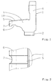
- FIG. 1 and 2 a possible embodiment of a coupling body for a synchronizer is shown, wherein the Fig. 3 to 10 represent different embodiments of a synchronizer ring for a synchronization device.
- synchronizing device is usually used for synchronizing idler gears on a shaft of a vehicle transmission and comprises at least one synchronizer ring 8 and at least one coupling body 1.
- the coupling body 1 is positively connected via a toothing 2 with the not shown loose wheel of the shaft, which is to be synchronized connected .
- the synchronizer ring 8 regardless of its chosen embodiment, positively connected to a sliding sleeve, which in turn is connected via a synchronizer body 15 rotatably connected to the shaft of the vehicle transmission.
- To synchronize the idler gear of the synchronizer ring 8 is frictionally connected to the coupling body 1 via the respective friction surfaces.
- the friction surfaces with a coolant such as oil, applied.
- the proposed coupling body 1 has an annular base body 3, to which an outer cone 4 with a friction surface 19 is formed.
- the friction surface 19 of the outer cone 4 has a plurality of axially extending flats 5.
- an annular ⁇ lfangnut 6 is provided for collecting the oil provided by the shaft through corresponding holes.
- 4 recesses 7 are provided on the front side of the outer cone in the radial direction. The recesses 7 are arranged distributed as radial cutouts over the circumference, as is made Fig. 2 is seen.
- the front-side recesses 7 connect the ⁇ lfangnut 6 with the flats 5, so that the oil collected in the ⁇ lfangnut 6 due to the centrifugal force on the recesses 7 can get into the flats 5.
- the oil can then wet the entire friction surface 19 of the outer cone 4.
- This embodiment can be used primarily in synchronization devices in which the coupling body 1 has a friction surface 19 made of steel and the synchronizer ring 8 is provided with a friction lining 9 consisting of molybdenum.
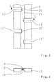
- the synchronizer ring 8 comprises an annular base body 10, to which an inner cone 11 is formed, on the surface of a friction lining 9 is applied, wherein in 3 and 4 only the friction lining 9 of the synchronizer ring 8 is shown.
- Fig. 3 shows the unrolled in the plane friction lining 9 of the synchronizer ring. 8
- the friction lining 9 is designed annular and has at each edge region a plurality of axially extending grooves 12, 12 'and 13, 13'. Both the grooves 12, 12 'and the grooves 13, 13' have a length which is dimensioned such that the grooves 12, 12 'and 13, 13' cut an annular groove 14 arranged centrally on the friction lining 9.
- the outlet 20, 20 'of each groove 12, 12' can, as in Fig. 3 indicated by dashed line, have in longitudinal section an arc shape with a predetermined radius. There are other forms possible.
- each groove 12, 12 'and 13, 13' is dimensioned so that it corresponds approximately to the thickness of the friction lining 9. Furthermore, the grooves 12, 12 'are each offset from the grooves 13, 13' at the opposite edge of the friction lining 9.
- the oil in each case in the frontally disposed grooves 12, 12 'penetrate, to then be tangentially transported in the annular groove 14 and finally by the grooves 13, 13' exit again. Due to the tangential relative movement of the coupling body 1 relative to the friction lining 9 of the synchronizer ring 8, the friction surfaces are wetted and cooled during the synchronization process.
- the annular groove 14 with the connected grooves 12, 12 'and 13, 13' allows an oil purging and thus improved heat dissipation at the friction surfaces of the synchronizer ring 8 and the coupling body. 1
- FIGS. 5 and 6 a second embodiment of the synchronizer ring 8 is shown.
- two adjacent grooves 12 and 12 'or 13 and 13' are arranged mirror-symmetrically to each other.
- the volume flow through the grooves 12, 12 'and 13, 13' is increased and as a result the cooling is further improved.
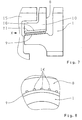
- FIGS. 7 and 8 a third embodiment of the synchronizer ring 8 is shown, wherein Fig. 7 a partial view of a possible synchronization device with the synchronizer ring 8, the coupling body 1 and a synchronizer body 15 shows.
- the synchronizer ring 8 has a plurality of axial grooves 16 on its inner cone 11. The axial grooves 16 are arranged distributed over the circumference of the inner cone 11 at a predetermined distance from one another.
- the axial grooves 16 are provided above the friction lining 9. This is both off Fig. 7 as well as Fig. 8 seen.
- the axial grooves 16 can be produced by a suitable pressing method prior to the application of the friction lining 9.
- the friction lining 9 is thus only on web areas between the axial grooves 16, as in particular from Fig. 8 is apparent.
- the axial grooves 16 are z. B. supplied with oil from the ⁇ lfangnut 6 of the coupling body 1, not shown. In this way, the oil can enter the end faces in the axial grooves 16 and then flow through the axial grooves 16. As a result, the friction lining 9 is cooled and the resulting heat dissipated by the oil.
- the axial grooves 16 have a conical shape, so that due to the centrifugal force, a pump effect is effected in the axial grooves 16, which further increases the volume flow of the oil and thus enhances the cooling effect.
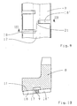
- FIGS. 9 and 10 is a fourth, inventive embodiment of the synchronizer ring 8 is shown.
- the inner cone 11 of the synchronizer ring 8 has an annular groove 17, which is arranged approximately centrally on the surface of the inner cone 11.
- the annular groove 17 is at least cut by the axially extending in the friction lining 9 grooves 18, 18 '. In this way, oil can pass from the frontal groove 18 in the annular groove 17 to then be able to escape through the inside groove 18 'from the friction dressing again. Consequently, optimal cooling of the friction lining 9 of the synchronizer ring 8 is ensured even in this embodiment.
Landscapes
- Engineering & Computer Science (AREA)
- General Engineering & Computer Science (AREA)
- Mechanical Engineering (AREA)
- Mechanical Operated Clutches (AREA)
Claims (9)
- Bague de synchronisation pour un dispositif de synchronisation, comprenant un corps de base (10) de forme annulaire, sur lequel est formé un cône interne (11), sur lequel est prévue une garniture de friction (9), caractérisée en ce que le cône interne (11) présente au moins une rainure annulaire (17) et en ce que la garniture de friction annulaire (9) présente sur chaque bord plusieurs rainures axiales (18, 18') réparties sur la périphérie, qui sont à chaque fois connectées fluidiquement à la rainure annulaire (17).
- Bague de synchronisation selon la revendication 1, caractérisée en ce que la rainure annulaire (17) s'étend approximativement centralement à la surface du cône interne (11).
- Bague de synchronisation selon l'une quelconque des revendications 1 ou 2, caractérisée en ce que les rainures (18, 18') commençant à chaque fois au niveau des bords de la garniture de friction (9) sont disposées de manière décalée les unes par rapport aux autres.
- Bague de synchronisation selon l'une quelconque des revendications 1 à 3, caractérisée en ce que la profondeur de chaque rainure (18, 18') correspond approximativement à l'épaisseur de la garniture de friction (9).
- Bague de synchronisation selon l'une quelconque des revendications 1 à 4, caractérisée en ce que la sortie (21) de chaque rainure (18, 18') est approximativement en forme d'arc en coupe longitudinale.
- Bague de synchronisation selon l'une quelconque des revendications 1 à 5, caractérisée en ce que la longueur de chaque rainure (18, 18') est dimensionnée de telle sorte que la rainure (18, 18') coupe la rainure annulaire (17).
- Bague de synchronisation selon l'une quelconque des revendications 1 à 6, caractérisée en ce qu'il est prévu un matériau organique en tant que garniture de friction (9) de la bague de synchronisation (8).
- Bague de synchronisation selon la revendication 7, caractérisée en ce que l'on prévoit du carbone comme matériau pour la garniture de friction (9).
- Dispositif de synchronisation pour synchroniser des pignons fous sur un arbre d'une transmission de véhicule, comprenant au moins une bague de synchronisation (8) selon l'une quelconque des revendications précédentes et un corps d'accouplement (1) associé.
Applications Claiming Priority (2)
| Application Number | Priority Date | Filing Date | Title |
|---|---|---|---|
| DE102007010764A DE102007010764A1 (de) | 2007-03-06 | 2007-03-06 | Kupplungskörper und Synchronring für eine Synchronisierungseinrichtung |
| PCT/EP2008/052138 WO2008107315A2 (fr) | 2007-03-06 | 2008-02-21 | Corps d'accouplement et bague de synchronisation pour un dispositif de synchronisation |
Publications (2)
| Publication Number | Publication Date |
|---|---|
| EP2118508A2 EP2118508A2 (fr) | 2009-11-18 |
| EP2118508B1 true EP2118508B1 (fr) | 2011-08-17 |
Family
ID=39345479
Family Applications (1)
| Application Number | Title | Priority Date | Filing Date |
|---|---|---|---|
| EP08709168A Not-in-force EP2118508B1 (fr) | 2007-03-06 | 2008-02-21 | Bague de synchronisation pour un dispositif de synchronisation |
Country Status (6)
| Country | Link |
|---|---|
| EP (1) | EP2118508B1 (fr) |
| JP (1) | JP5283637B2 (fr) |
| CN (1) | CN101622466B (fr) |
| AT (1) | ATE520890T1 (fr) |
| DE (1) | DE102007010764A1 (fr) |
| WO (1) | WO2008107315A2 (fr) |
Families Citing this family (13)
| Publication number | Priority date | Publication date | Assignee | Title |
|---|---|---|---|---|
| DE102008046916B4 (de) * | 2008-09-12 | 2020-03-12 | Volkswagen Ag | Synchronisiereinrichtung für ein Kraftfahrzeug |
| DE102011103344A1 (de) * | 2011-05-27 | 2012-11-29 | PMG Füssen GmbH | Verfahren zur herstellung eines bauteiles mit einem reibbelag |
| DE102011120343B4 (de) * | 2011-11-30 | 2016-03-31 | Getrag Getriebe- Und Zahnradfabrik Hermann Hagenmeyer Gmbh & Cie Kg | Verfahren zur Herstellung eines Kupplungskörpers sowie Kupplungskörper für eine Synchronisiereinrichtung |
| CN102425619B (zh) * | 2012-01-01 | 2013-03-27 | 赵孝民 | 一种同步锥毂 |
| DE102012221716A1 (de) * | 2012-11-28 | 2014-05-28 | Schaeffler Technologies Gmbh & Co. Kg | Synchronisiereinrichtung eines Kraftfahrzeug-Zahnräderwechselgetriebes |
| DE102013215617C5 (de) | 2013-08-08 | 2018-07-19 | Schaeffler Technologies AG & Co. KG | Kupplungskörper einer Synchronisiervorrichtung |
| DE102015212043A1 (de) | 2015-06-29 | 2016-12-29 | Zf Friedrichshafen Ag | Verfahren und Vorrichtung zum Fügen einer Welle-Nabe-Verbindung |
| DE102015214017A1 (de) | 2015-07-24 | 2017-01-26 | Zf Friedrichshafen Ag | Verfahren und Vorrichtung zur Bestimmung eines Verschleißzustands eines Synchronrings sowie landwirtschaftliche Arbeitsmaschine |
| DE102016113422A1 (de) | 2016-07-20 | 2018-01-25 | Getrag Getriebe- Und Zahnradfabrik Hermann Hagenmeyer Gmbh & Cie Kg | Reibring und Mehrfachkegel-Synchronschaltkupplung |
| CN106224401A (zh) * | 2016-08-31 | 2016-12-14 | 重庆铁马工业集团有限公司 | 一种同步器锥体增加锥面润滑方法 |
| EP3473879B1 (fr) * | 2017-10-17 | 2020-09-30 | Ningbo Geely Automobile Research & Development Co. Ltd. | Bague de synchronisation |
| EP3708860B1 (fr) * | 2019-03-13 | 2021-08-04 | Ningbo Geely Automobile Research & Development Co. Ltd. | Bague de synchronisation |
| EP3748184B1 (fr) * | 2019-06-05 | 2023-01-25 | Ningbo Geely Automobile Research & Development Co., Ltd. | Bague de synchronisation |
Family Cites Families (26)
| Publication number | Priority date | Publication date | Assignee | Title |
|---|---|---|---|---|
| DE2008945A1 (de) * | 1969-04-08 | 1970-11-05 | Ford-Werke AG, 5000 Köln-Deutz | Zahnradeinheit für Getriebe, insbesondere for Kraftfahrzeuge |
| DE2055345A1 (de) | 1970-11-11 | 1972-05-18 | Zahnradfabrik Friedrichshafen | Synchronisierring in Schaltgetrieben |
| JPS536753Y2 (fr) * | 1973-05-09 | 1978-02-21 | ||
| JPS5139152U (fr) * | 1974-09-19 | 1976-03-24 | ||
| DE2744994C2 (de) | 1977-10-06 | 1985-08-29 | Stieber Division Der Borg-Warner Gmbh, 6900 Heidelberg | Verfahren zur Herstellung eines Synchronosierringes |
| DE3113650C2 (de) * | 1981-04-04 | 1989-02-02 | Klöckner-Humboldt-Deutz AG, 5000 Köln | Synchronisiereinrichtung, insbesondere für das Wechselgetriebe eines Kraftfahrzeugs |
| JPS59187114A (ja) | 1983-04-06 | 1984-10-24 | Kyowa Gokin Kk | 車輛変速機における同期リング |
| DE3417813C1 (de) | 1984-05-14 | 1985-06-05 | Sinterstahl GmbH, 8958 Füssen | Verwendung von Streusinter-Reibbelaegen in Reibkupplungen oder -bremsen |
| US4878282A (en) * | 1987-09-04 | 1989-11-07 | Borg-Warner Automotive Gmbh | Method for the production of friction plates, synchronizing blocker rings or similar structures |
| JPH0171228U (fr) * | 1987-10-31 | 1989-05-12 | ||
| JPH0241723U (fr) * | 1988-09-14 | 1990-03-22 | ||
| DE4017142A1 (de) * | 1990-05-28 | 1991-12-05 | Kloeckner Humboldt Deutz Ag | Synchronisiereinrichtung fuer zahnradwechselgetriebe |
| JP2605890Y2 (ja) * | 1993-05-13 | 2000-08-21 | 日産ディーゼル工業株式会社 | 変速機の同期装置 |
| JP3781811B2 (ja) * | 1995-09-22 | 2006-05-31 | Gkn ドライブライン トルクテクノロジー株式会社 | 差動制限装置 |
| JPH09119504A (ja) * | 1995-10-26 | 1997-05-06 | Nsk Warner Kk | トルクコンバータに用いるロックアップクラッチ |
| JPH09144773A (ja) * | 1995-11-20 | 1997-06-03 | Kinousei Mokushitsu Shinsozai Gijutsu Kenkyu Kumiai | ウッドセラミックスからなる摩擦材の層を具えたシンクロナイザーリング |
| JPH11190362A (ja) * | 1997-12-26 | 1999-07-13 | Nippon Piston Ring Co Ltd | シンクロナイザリング |
| FR2789143B1 (fr) * | 1999-01-29 | 2001-03-02 | Valeo | Dispositif mettant en oeuvre un frottement en milieu liquide et comportant une garniture de frottement a porosite controlee |
| DE10036087B4 (de) * | 2000-07-25 | 2009-10-01 | Schaeffler Kg | Gangrad mit einem Kupplungskörper |
| JP2002235772A (ja) * | 2001-02-13 | 2002-08-23 | Kyowa Metal Work Co Ltd | 円錐クラッチの摩擦材貼付方法 |
| JP2002242954A (ja) * | 2001-02-14 | 2002-08-28 | Aisin Aw Co Ltd | 摩擦板 |
| CN1802518B (zh) * | 2003-06-10 | 2010-04-28 | 奥依列斯工业株式会社 | 同步器环 |
| JP4756555B2 (ja) * | 2003-10-02 | 2011-08-24 | ズルツァー フリクション システムズ (ジャーマニー) ゲー.エム.ベー.ハー. | 摩擦フェーシングおよび摩擦フェーシングの提供方法 |
| AT502647B1 (de) * | 2004-01-15 | 2007-05-15 | Miba Sinter Austria Gmbh | Synchronisierring für ein zahnradwechselgetriebe |
| JP2006009953A (ja) * | 2004-06-25 | 2006-01-12 | Nissan Diesel Motor Co Ltd | 変速機の同期装置 |
| JP4593983B2 (ja) * | 2004-06-25 | 2010-12-08 | Udトラックス株式会社 | 変速機の同期装置 |
-
2007
- 2007-03-06 DE DE102007010764A patent/DE102007010764A1/de not_active Withdrawn
-
2008
- 2008-02-21 WO PCT/EP2008/052138 patent/WO2008107315A2/fr active Application Filing
- 2008-02-21 CN CN2008800068026A patent/CN101622466B/zh not_active Expired - Fee Related
- 2008-02-21 EP EP08709168A patent/EP2118508B1/fr not_active Not-in-force
- 2008-02-21 AT AT08709168T patent/ATE520890T1/de active
- 2008-02-21 JP JP2009552159A patent/JP5283637B2/ja not_active Expired - Fee Related
Also Published As
| Publication number | Publication date |
|---|---|
| CN101622466A (zh) | 2010-01-06 |
| WO2008107315A2 (fr) | 2008-09-12 |
| JP2010520429A (ja) | 2010-06-10 |
| JP5283637B2 (ja) | 2013-09-04 |
| EP2118508A2 (fr) | 2009-11-18 |
| WO2008107315A3 (fr) | 2008-12-18 |
| ATE520890T1 (de) | 2011-09-15 |
| DE102007010764A1 (de) | 2008-09-11 |
| CN101622466B (zh) | 2011-10-12 |
Similar Documents
| Publication | Publication Date | Title |
|---|---|---|
| EP2118508B1 (fr) | Bague de synchronisation pour un dispositif de synchronisation | |
| EP2104790B1 (fr) | Bague de synchronisation d'un dispositif de synchronisation | |
| EP3250836B1 (fr) | Palier lisse d'un élément rotatif sur un boulon de coussinet, notamment d'un pignon satellite sur un arbre de pignon satellite d'un engrenage planétaires | |
| DE102007044856B4 (de) | Kupplungsanordnung mit einer Kupplungsscheibe mit inneren Fluidkanälen | |
| EP0521843B1 (fr) | Anneau de friction | |
| AT516124A1 (de) | Reiblamelle | |
| EP3273085B1 (fr) | Bague de frottement et embrayage synchronisé multi-cônes | |
| DE10315169A1 (de) | Kupplungsanordnung | |
| EP1141567B2 (fr) | Anneau de synchronisation fabrique sans enlevement de copeaux, a surfaces de frottement structurees | |
| EP2028386A1 (fr) | Anneau synchrone pour un dispositif de synchronisation, ébauche de garniture de friction et procédé destiné à la fabrication d'un anneau synchrone | |
| DE102010003077A1 (de) | Gleitlagerschale | |
| DE102008032458B4 (de) | Nasskupplung | |
| DE102006057112B4 (de) | Reibteil für eine reibschlüssig arbeitende Einrichtung und reibschlüssig arbeitende Einrichtung mit einem solchen Reibteil | |
| EP2994661B2 (fr) | Embrayage à couple de freinage réduit | |
| DE102010054253B4 (de) | Nasslaufende Kraftfahrzeugreibkupplung | |
| DE102016102701A1 (de) | Synchronisiervorrichtung und Synchronisationsverfahren | |
| DE102011120343B4 (de) | Verfahren zur Herstellung eines Kupplungskörpers sowie Kupplungskörper für eine Synchronisiereinrichtung | |
| EP3217031A1 (fr) | Embrayage à disque | |
| DE102013222364B4 (de) | Reibungskupplung und Platte mit teilweise erhabenen Segmentfugen | |
| AT520443B1 (de) | Getriebe-Synchronisationseinrichtung | |
| DE102009032180A1 (de) | Verfahren zum Herstellen einer Reiblamelle sowie Reiblamelle | |
| EP3084250A1 (fr) | Composant fabriqué par métallurgie des poudres | |
| EP3179124B1 (fr) | Lamelle de friction | |
| AT15554U1 (de) | Reiblamelle | |
| DE102013212281A1 (de) | Kupplungslamelle für eine nasslaufende Reibkupplung |
Legal Events
| Date | Code | Title | Description |
|---|---|---|---|
| PUAI | Public reference made under article 153(3) epc to a published international application that has entered the european phase |
Free format text: ORIGINAL CODE: 0009012 |
|
| 17P | Request for examination filed |
Effective date: 20090908 |
|
| AK | Designated contracting states |
Kind code of ref document: A2 Designated state(s): AT BE BG CH CY CZ DE DK EE ES FI FR GB GR HR HU IE IS IT LI LT LU LV MC MT NL NO PL PT RO SE SI SK TR |
|
| GRAP | Despatch of communication of intention to grant a patent |
Free format text: ORIGINAL CODE: EPIDOSNIGR1 |
|
| RTI1 | Title (correction) |
Free format text: SYNCHRONIZER RING FOR A SYNCHRONIZATION DEVICE |
|
| DAX | Request for extension of the european patent (deleted) | ||
| GRAS | Grant fee paid |
Free format text: ORIGINAL CODE: EPIDOSNIGR3 |
|
| GRAA | (expected) grant |
Free format text: ORIGINAL CODE: 0009210 |
|
| AK | Designated contracting states |
Kind code of ref document: B1 Designated state(s): AT BE BG CH CY CZ DE DK EE ES FI FR GB GR HR HU IE IS IT LI LT LU LV MC MT NL NO PL PT RO SE SI SK TR |
|
| REG | Reference to a national code |
Ref country code: GB Ref legal event code: FG4D Free format text: NOT ENGLISH |
|
| REG | Reference to a national code |
Ref country code: CH Ref legal event code: EP |
|
| REG | Reference to a national code |
Ref country code: IE Ref legal event code: FG4D Free format text: LANGUAGE OF EP DOCUMENT: GERMAN |
|
| REG | Reference to a national code |
Ref country code: SE Ref legal event code: TRGR |
|
| REG | Reference to a national code |
Ref country code: DE Ref legal event code: R096 Ref document number: 502008004522 Country of ref document: DE Effective date: 20111117 |
|
| REG | Reference to a national code |
Ref country code: NL Ref legal event code: VDEP Effective date: 20110817 |
|
| LTIE | Lt: invalidation of european patent or patent extension |
Effective date: 20110817 |
|
| PG25 | Lapsed in a contracting state [announced via postgrant information from national office to epo] |
Ref country code: LT Free format text: LAPSE BECAUSE OF FAILURE TO SUBMIT A TRANSLATION OF THE DESCRIPTION OR TO PAY THE FEE WITHIN THE PRESCRIBED TIME-LIMIT Effective date: 20110817 Ref country code: PT Free format text: LAPSE BECAUSE OF FAILURE TO SUBMIT A TRANSLATION OF THE DESCRIPTION OR TO PAY THE FEE WITHIN THE PRESCRIBED TIME-LIMIT Effective date: 20111219 Ref country code: NO Free format text: LAPSE BECAUSE OF FAILURE TO SUBMIT A TRANSLATION OF THE DESCRIPTION OR TO PAY THE FEE WITHIN THE PRESCRIBED TIME-LIMIT Effective date: 20111117 Ref country code: IS Free format text: LAPSE BECAUSE OF FAILURE TO SUBMIT A TRANSLATION OF THE DESCRIPTION OR TO PAY THE FEE WITHIN THE PRESCRIBED TIME-LIMIT Effective date: 20111217 Ref country code: NL Free format text: LAPSE BECAUSE OF FAILURE TO SUBMIT A TRANSLATION OF THE DESCRIPTION OR TO PAY THE FEE WITHIN THE PRESCRIBED TIME-LIMIT Effective date: 20110817 Ref country code: FI Free format text: LAPSE BECAUSE OF FAILURE TO SUBMIT A TRANSLATION OF THE DESCRIPTION OR TO PAY THE FEE WITHIN THE PRESCRIBED TIME-LIMIT Effective date: 20110817 |
|
| PG25 | Lapsed in a contracting state [announced via postgrant information from national office to epo] |
Ref country code: GR Free format text: LAPSE BECAUSE OF FAILURE TO SUBMIT A TRANSLATION OF THE DESCRIPTION OR TO PAY THE FEE WITHIN THE PRESCRIBED TIME-LIMIT Effective date: 20111118 Ref country code: LV Free format text: LAPSE BECAUSE OF FAILURE TO SUBMIT A TRANSLATION OF THE DESCRIPTION OR TO PAY THE FEE WITHIN THE PRESCRIBED TIME-LIMIT Effective date: 20110817 Ref country code: SI Free format text: LAPSE BECAUSE OF FAILURE TO SUBMIT A TRANSLATION OF THE DESCRIPTION OR TO PAY THE FEE WITHIN THE PRESCRIBED TIME-LIMIT Effective date: 20110817 Ref country code: CY Free format text: LAPSE BECAUSE OF FAILURE TO SUBMIT A TRANSLATION OF THE DESCRIPTION OR TO PAY THE FEE WITHIN THE PRESCRIBED TIME-LIMIT Effective date: 20110817 Ref country code: PL Free format text: LAPSE BECAUSE OF FAILURE TO SUBMIT A TRANSLATION OF THE DESCRIPTION OR TO PAY THE FEE WITHIN THE PRESCRIBED TIME-LIMIT Effective date: 20110817 |
|
| REG | Reference to a national code |
Ref country code: IE Ref legal event code: FD4D |
|
| PG25 | Lapsed in a contracting state [announced via postgrant information from national office to epo] |
Ref country code: CZ Free format text: LAPSE BECAUSE OF FAILURE TO SUBMIT A TRANSLATION OF THE DESCRIPTION OR TO PAY THE FEE WITHIN THE PRESCRIBED TIME-LIMIT Effective date: 20110817 Ref country code: IE Free format text: LAPSE BECAUSE OF FAILURE TO SUBMIT A TRANSLATION OF THE DESCRIPTION OR TO PAY THE FEE WITHIN THE PRESCRIBED TIME-LIMIT Effective date: 20110817 Ref country code: SK Free format text: LAPSE BECAUSE OF FAILURE TO SUBMIT A TRANSLATION OF THE DESCRIPTION OR TO PAY THE FEE WITHIN THE PRESCRIBED TIME-LIMIT Effective date: 20110817 |
|
| PG25 | Lapsed in a contracting state [announced via postgrant information from national office to epo] |
Ref country code: EE Free format text: LAPSE BECAUSE OF FAILURE TO SUBMIT A TRANSLATION OF THE DESCRIPTION OR TO PAY THE FEE WITHIN THE PRESCRIBED TIME-LIMIT Effective date: 20110817 Ref country code: RO Free format text: LAPSE BECAUSE OF FAILURE TO SUBMIT A TRANSLATION OF THE DESCRIPTION OR TO PAY THE FEE WITHIN THE PRESCRIBED TIME-LIMIT Effective date: 20110817 |
|
| PLBE | No opposition filed within time limit |
Free format text: ORIGINAL CODE: 0009261 |
|
| STAA | Information on the status of an ep patent application or granted ep patent |
Free format text: STATUS: NO OPPOSITION FILED WITHIN TIME LIMIT |
|
| PG25 | Lapsed in a contracting state [announced via postgrant information from national office to epo] |
Ref country code: DK Free format text: LAPSE BECAUSE OF FAILURE TO SUBMIT A TRANSLATION OF THE DESCRIPTION OR TO PAY THE FEE WITHIN THE PRESCRIBED TIME-LIMIT Effective date: 20110817 |
|
| PGFP | Annual fee paid to national office [announced via postgrant information from national office to epo] |
Ref country code: IT Payment date: 20120216 Year of fee payment: 5 |
|
| 26N | No opposition filed |
Effective date: 20120521 |
|
| PG25 | Lapsed in a contracting state [announced via postgrant information from national office to epo] |
Ref country code: HR Free format text: LAPSE BECAUSE OF FAILURE TO SUBMIT A TRANSLATION OF THE DESCRIPTION OR TO PAY THE FEE WITHIN THE PRESCRIBED TIME-LIMIT Effective date: 20120328 |
|
| BERE | Be: lapsed |
Owner name: ZF FRIEDRICHSHAFEN A.G. Effective date: 20120228 |
|
| REG | Reference to a national code |
Ref country code: DE Ref legal event code: R097 Ref document number: 502008004522 Country of ref document: DE Effective date: 20120521 |
|
| PG25 | Lapsed in a contracting state [announced via postgrant information from national office to epo] |
Ref country code: MC Free format text: LAPSE BECAUSE OF NON-PAYMENT OF DUE FEES Effective date: 20120229 |
|
| REG | Reference to a national code |
Ref country code: CH Ref legal event code: PL |
|
| GBPC | Gb: european patent ceased through non-payment of renewal fee |
Effective date: 20120221 |
|
| PG25 | Lapsed in a contracting state [announced via postgrant information from national office to epo] |
Ref country code: LI Free format text: LAPSE BECAUSE OF NON-PAYMENT OF DUE FEES Effective date: 20120229 Ref country code: CH Free format text: LAPSE BECAUSE OF NON-PAYMENT OF DUE FEES Effective date: 20120229 |
|
| REG | Reference to a national code |
Ref country code: FR Ref legal event code: ST Effective date: 20121031 |
|
| PG25 | Lapsed in a contracting state [announced via postgrant information from national office to epo] |
Ref country code: BE Free format text: LAPSE BECAUSE OF NON-PAYMENT OF DUE FEES Effective date: 20120228 |
|
| PG25 | Lapsed in a contracting state [announced via postgrant information from national office to epo] |
Ref country code: GB Free format text: LAPSE BECAUSE OF NON-PAYMENT OF DUE FEES Effective date: 20120221 Ref country code: FR Free format text: LAPSE BECAUSE OF NON-PAYMENT OF DUE FEES Effective date: 20120229 |
|
| PG25 | Lapsed in a contracting state [announced via postgrant information from national office to epo] |
Ref country code: ES Free format text: LAPSE BECAUSE OF FAILURE TO SUBMIT A TRANSLATION OF THE DESCRIPTION OR TO PAY THE FEE WITHIN THE PRESCRIBED TIME-LIMIT Effective date: 20111128 |
|
| PGFP | Annual fee paid to national office [announced via postgrant information from national office to epo] |
Ref country code: SE Payment date: 20130212 Year of fee payment: 6 |
|
| PG25 | Lapsed in a contracting state [announced via postgrant information from national office to epo] |
Ref country code: BG Free format text: LAPSE BECAUSE OF FAILURE TO SUBMIT A TRANSLATION OF THE DESCRIPTION OR TO PAY THE FEE WITHIN THE PRESCRIBED TIME-LIMIT Effective date: 20111117 |
|
| PG25 | Lapsed in a contracting state [announced via postgrant information from national office to epo] |
Ref country code: MT Free format text: LAPSE BECAUSE OF FAILURE TO SUBMIT A TRANSLATION OF THE DESCRIPTION OR TO PAY THE FEE WITHIN THE PRESCRIBED TIME-LIMIT Effective date: 20110817 |
|
| PG25 | Lapsed in a contracting state [announced via postgrant information from national office to epo] |
Ref country code: HR Free format text: LAPSE BECAUSE OF FAILURE TO SUBMIT A TRANSLATION OF THE DESCRIPTION OR TO PAY THE FEE WITHIN THE PRESCRIBED TIME-LIMIT Effective date: 20110817 |
|
| REG | Reference to a national code |
Ref country code: AT Ref legal event code: MM01 Ref document number: 520890 Country of ref document: AT Kind code of ref document: T Effective date: 20130221 |
|
| PG25 | Lapsed in a contracting state [announced via postgrant information from national office to epo] |
Ref country code: TR Free format text: LAPSE BECAUSE OF FAILURE TO SUBMIT A TRANSLATION OF THE DESCRIPTION OR TO PAY THE FEE WITHIN THE PRESCRIBED TIME-LIMIT Effective date: 20110817 |
|
| PG25 | Lapsed in a contracting state [announced via postgrant information from national office to epo] |
Ref country code: AT Free format text: LAPSE BECAUSE OF NON-PAYMENT OF DUE FEES Effective date: 20130221 Ref country code: LU Free format text: LAPSE BECAUSE OF NON-PAYMENT OF DUE FEES Effective date: 20120221 |
|
| PG25 | Lapsed in a contracting state [announced via postgrant information from national office to epo] |
Ref country code: HU Free format text: LAPSE BECAUSE OF FAILURE TO SUBMIT A TRANSLATION OF THE DESCRIPTION OR TO PAY THE FEE WITHIN THE PRESCRIBED TIME-LIMIT Effective date: 20080221 |
|
| REG | Reference to a national code |
Ref country code: SE Ref legal event code: EUG |
|
| PG25 | Lapsed in a contracting state [announced via postgrant information from national office to epo] |
Ref country code: SE Free format text: LAPSE BECAUSE OF NON-PAYMENT OF DUE FEES Effective date: 20140222 |
|
| PGFP | Annual fee paid to national office [announced via postgrant information from national office to epo] |
Ref country code: DE Payment date: 20150218 Year of fee payment: 8 |
|
| PG25 | Lapsed in a contracting state [announced via postgrant information from national office to epo] |
Ref country code: IT Free format text: LAPSE BECAUSE OF NON-PAYMENT OF DUE FEES Effective date: 20140221 |
|
| REG | Reference to a national code |
Ref country code: DE Ref legal event code: R119 Ref document number: 502008004522 Country of ref document: DE |
|
| PG25 | Lapsed in a contracting state [announced via postgrant information from national office to epo] |
Ref country code: DE Free format text: LAPSE BECAUSE OF NON-PAYMENT OF DUE FEES Effective date: 20160901 |