EP2114188B1 - Schnürsystem für schuhe - Google Patents
Schnürsystem für schuhe Download PDFInfo
- Publication number
- EP2114188B1 EP2114188B1 EP07815175.0A EP07815175A EP2114188B1 EP 2114188 B1 EP2114188 B1 EP 2114188B1 EP 07815175 A EP07815175 A EP 07815175A EP 2114188 B1 EP2114188 B1 EP 2114188B1
- Authority
- EP
- European Patent Office
- Prior art keywords
- shoe
- shoelace
- shoes
- lacing
- entry
- Prior art date
- Legal status (The legal status is an assumption and is not a legal conclusion. Google has not performed a legal analysis and makes no representation as to the accuracy of the status listed.)
- Not-in-force
Links
Images


Classifications
-
- A—HUMAN NECESSITIES
- A43—FOOTWEAR
- A43C—FASTENINGS OR ATTACHMENTS OF FOOTWEAR; LACES IN GENERAL
- A43C1/00—Shoe lacing fastenings
-
- B—PERFORMING OPERATIONS; TRANSPORTING
- B60—VEHICLES IN GENERAL
- B60T—VEHICLE BRAKE CONTROL SYSTEMS OR PARTS THEREOF; BRAKE CONTROL SYSTEMS OR PARTS THEREOF, IN GENERAL; ARRANGEMENT OF BRAKING ELEMENTS ON VEHICLES IN GENERAL; PORTABLE DEVICES FOR PREVENTING UNWANTED MOVEMENT OF VEHICLES; VEHICLE MODIFICATIONS TO FACILITATE COOLING OF BRAKES
- B60T11/00—Transmitting braking action from initiating means to ultimate brake actuator without power assistance or drive or where such assistance or drive is irrelevant
- B60T11/10—Transmitting braking action from initiating means to ultimate brake actuator without power assistance or drive or where such assistance or drive is irrelevant transmitting by fluid means, e.g. hydraulic
- B60T11/26—Reservoirs
-
- B—PERFORMING OPERATIONS; TRANSPORTING
- B60—VEHICLES IN GENERAL
- B60T—VEHICLE BRAKE CONTROL SYSTEMS OR PARTS THEREOF; BRAKE CONTROL SYSTEMS OR PARTS THEREOF, IN GENERAL; ARRANGEMENT OF BRAKING ELEMENTS ON VEHICLES IN GENERAL; PORTABLE DEVICES FOR PREVENTING UNWANTED MOVEMENT OF VEHICLES; VEHICLE MODIFICATIONS TO FACILITATE COOLING OF BRAKES
- B60T17/00—Component parts, details, or accessories of power brake systems not covered by groups B60T8/00, B60T13/00 or B60T15/00, or presenting other characteristic features
- B60T17/06—Applications or arrangements of reservoirs
-
- Y—GENERAL TAGGING OF NEW TECHNOLOGICAL DEVELOPMENTS; GENERAL TAGGING OF CROSS-SECTIONAL TECHNOLOGIES SPANNING OVER SEVERAL SECTIONS OF THE IPC; TECHNICAL SUBJECTS COVERED BY FORMER USPC CROSS-REFERENCE ART COLLECTIONS [XRACs] AND DIGESTS
- Y10—TECHNICAL SUBJECTS COVERED BY FORMER USPC
- Y10T—TECHNICAL SUBJECTS COVERED BY FORMER US CLASSIFICATION
- Y10T24/00—Buckles, buttons, clasps, etc.
- Y10T24/37—Drawstring, laced-fastener, or separate essential cooperating device therefor
-
- Y—GENERAL TAGGING OF NEW TECHNOLOGICAL DEVELOPMENTS; GENERAL TAGGING OF CROSS-SECTIONAL TECHNOLOGIES SPANNING OVER SEVERAL SECTIONS OF THE IPC; TECHNICAL SUBJECTS COVERED BY FORMER USPC CROSS-REFERENCE ART COLLECTIONS [XRACs] AND DIGESTS
- Y10—TECHNICAL SUBJECTS COVERED BY FORMER USPC
- Y10T—TECHNICAL SUBJECTS COVERED BY FORMER US CLASSIFICATION
- Y10T24/00—Buckles, buttons, clasps, etc.
- Y10T24/37—Drawstring, laced-fastener, or separate essential cooperating device therefor
- Y10T24/3737—Drawstring, laced-fastener, or separate essential cooperating device therefor having lacing directing means in particular pattern
Definitions
- the invention relates to a lacing system for shoes of all kinds, especially for sports shoes, with a shoelace, two ends are provided for contraction of the shoe and the course of the shoelace is at least in the instep and ball area without crossing, the frontal opening for entry into the shoe Has meandering course and has the opening for entry into the shoe interlocking cloth.
- lacing systems are designed so that the laces od by loops or eyelets. Like. Are guided and alternately deflected on the left and right sides of the shoe upper and accordingly cross naturally.
- a disadvantage of this system occurs especially when the shoe is used as an innerboot, e.g. when the liner is covered by a shell. In this case, at the crossing points of the laces on the foot pressure points occur.
- padding is often installed below the lacing. Remedy can also create tongues, which are provided with a padding.
- WO 00/53045 A1 is another type of lacing system for shoes with tabs provided with guide elements, through which a fixed in the toe area shoe band is guided.
- This lacing system has only a single free end for contracting the shoe, which is passed through a closure device comprising a push button for releasing or detecting the shoe lace.
- the EP 1 618 929 A1 describes a skate having inter alia a lace assembly with a plurality of guide elements and a locking device.
- the shoelace is divided into a forefoot and a Riststrang, whereby a different tightening of the laces is possible.
- the object of the invention is to provide a lacing system by which the shortcomings of the previously known lacing systems are eliminated.
- the opening for entry into the shoe has interlocking tabs, which have guide elements for deflecting the shoelace at their ends.
- the distance between the guide element 4 of the lobe 8 and the additional element 9 is controlled according to the measure according to claim 2 and as a result, the draw angle of the shoelace also controllable, whereby the pulling action of the lacing specifically on the requirement profile of the shoe can be constructed ,
- Fig. 1 1 denotes the area of the ball and instep, and 2 denotes the area of the shaft which leads upwards from the ankle joints.
- 3 the shoelace is called, which is guided through openings 4.
- These openings 4 may be formed in a known manner as loops, loops, hooks, etc.
- the shoelace 3 may consist of one piece as in the present case. But it can also consist of two parts, in which case the shoelace is fastened on both sides in the tip region of the shoe, for example by knotting or sewing, with the upper of the shoe.
- the ends 3 'of the shoelace are usually knotted by the user. Clearly visible are the crossing points 5 of the shoelace.
- crossing points have the disadvantage that they produce firm pressure points with firm lacing, which lead to pain especially in the sensitive instep area of the human foot with firm lacing. Accordingly, in this case, the user must loosen the lacing, thereby deteriorating the grip of the foot in the shoe, and in the worst case, slipping the foot in the shoe causes painful blistering.
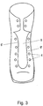
- FIG. 3 In the known embodiment of the shoe after Fig. 3 has these openings 4 for the shoelace and an opening 6, which serves to adapt the shoe in interaction with the lacing by the shoelace individually to the foot of each user.
- interlocking cloths 8 which have at their ends in a known manner means 4, such as eyelets, loops, hooks, etc., through which the shoelace 3 is guided. Furthermore, the shoe has additional means 9, such as, for example, along the line 9 'sewn, glued or riveted rag, which are also formed with means 4 for guiding the shoelace. If one follows the shoelace 3 in the direction of the arrows, it can be seen that at least in the instep and ball area through the lobes 8 and the additional means 9 no crossing points are present, the shoe can still be pulled together.
- This lacing system can be used on all types of lace-up shoes, i. for loafers, mountaineering boots, boots, sports shoes, e.g. Cross-country skiing boots, but also for hard plastic footwear provided with inner footwear, such as Inner shoes for ski boots, find use.
Landscapes
- Engineering & Computer Science (AREA)
- Transportation (AREA)
- Mechanical Engineering (AREA)
- Footwear And Its Accessory, Manufacturing Method And Apparatuses (AREA)
- Forging (AREA)
Description
- Die Erfindung betrifft ein Schnürsystem für Schuhe aller Art, insbesondere für Sportschuhe, mit einem Schuhband, wobei zwei Enden zum Zusammenziehen des Schuhs vorgesehen sind und der Verlauf des Schuhbandes zumindest im Rist- und Ballenbereich kreuzungsfrei ist, wobei die stirnseitige Öffnung zum Einstieg in den Schuh mäanderförmigen Verlauf aufweist und die Öffnung zum Einstieg in den Schuh ineinandergreifende Lappen aufweist. Üblicherweise sind Schnürsysteme so ausgebildet, dass die Schnürsenkel durch Schlaufen oder Ösen od. dgl. geführt werden und wechselweise auf der linken und rechten Seite des Schuhschaftes umgelenkt werden und sich dementsprechend naturgemäß überkreuzen. Ein Nachteil dieses Systems tritt vor allem dann auf, wenn der Schuh als Innenschuh verwendet wird, z.B. wenn der Innenschuh durch eine Schale abgedeckt ist. In diesem Fall treten an den Kreuzungspunkten der Schnürsenkel am Fuß Druckstellen auf. Um diesen Mangel zu beheben, werden häufig unterhalb der Schnürung Polsterungen eingebaut. Abhilfe können auch Zungen schaffen, die mit einer Polsterung versehen sind.
- Aus der
WO 00/53045 A1 - Durch die
FR 2 722 659 A1 WO 1989/08411 A1 - Ein weiteres Schnürsystem ist aus der
DE 197 10 702 A1 bekannt, bei dem selbstständig schließende, den Schnürsenkel fixierende Klemmvorrichtungen mit aufgerauter Klemmfläche vorgesehen sind. Die darin verwendeten Umlenkelemente umfassen abgerundete Auflageflächen, deren Krümmungsradius größer als der Durchmesser des Schnürsenkels ist. - Die
EP 1 618 929 A1 beschreibt einen Rollschuh, der u.a. eine Schnürsenkelanordnung mit einer Mehrzahl von Führungselementen und einer Feststellvorrichtung aufweist. Der Schnürsenkel ist dabei in einen Vorderfuß- und einen Riststrang unterteilt, wodurch ein unterschiedliches Anziehen der Schnürsenkel ermöglicht wird. - In der
DE 203 16 425 U1 ist eine Seilklemme zum Blockieren von Schnüren, Seilen und Bändern geoffenbart, bei der ein Seil durch Öffnungen in einem Gehäuse und um den Steg einer Lasche geführt wird, wobei die Lasche zum Lösen der Blockierung dient. - Schließlich zeigt die
DE 102 39 927 A1 eine Schnürvorrichtung für Schuhe mit einer Spann- bzw. Verriegelungsvorrichtung zum Spannen und Lösen des Schnürsenkels, wobei die Spann- bzw. Verriegelungsvorrichtung dabei als Ratschen- oder Drehverschluss ausgeführt ist. - Aufgabe der Erfindung ist die Schaffung eines Schnürsystems, durch welches die Mängel der bisher bekannten Schnürsysteme behoben werden.
- Diese Aufgabe wird durch die Maßnahme nach dem kennzeichnenden Teil des Anspruches 1 gelöst.
- Durch die Maßnahme nach Anspruch 1 wird eine besonders flexible Konstruktion ermöglicht, welche einerseits eine hervorragende Ristanpassung sicherstellt, andererseits beim Abbiegen des Schuhes, beispielsweise beim Gehen, keine Faltenbildung des Obermaterials zulässt.
- Die Öffnung zum Einstieg in den Schuh besitzt ineinadergreifende Lappen, welche an ihren Enden Führungselemente zur Umlenkung des Schuhbandes aufweisen.
- Durch die ineinandergreifenden Lappen ist gemäß der Maßnahme nach Anspruch 2 der Abstand zwischen dem Führungselement 4 des Lappens 8 und dem zusätzlichen Element 9 steuerbar und als Folge daraus der Zugwinkel des Schuhbandes ebenfalls steuerbar, wodurch die Zugwirkung der Schnürung gezielt auf das Anforderungsprofil des Schuhes konstruierbar ist.
- Weitere Vorteile werden durch die Maßnahmen nach den Unteransprüchen erzielt.
- Weitere Merkmale der Erfindung werden anhand der Zeichnungen erläutert, in welchen Ausführungsbeispiele des bekannten und des erfindungsgemäßen Schnürsystems dargestellt sind.
- Es zeigen:
- Fig. 1
- eine Vorderansicht eines herkömmlichen Schnürschuhes;
- Fig. 2
- den Schuh nach
Fig. 1 in Seitenansicht; - Fig. 3
- einen Schuh nach dem Stand der Technik ohne Schuhbänder;
- Fig. 4
- den erfindungsgemäßen Schnürschuh in Vorderansicht; und
- Fig. 5
- ein Detail nach
Fig. 4 in größerem Maßstab. - In
Fig. 1 ist mit 1 der Ballen- und Ristbereich sowie mit 2 der Schaftbereich bezeichnet, welcher von den Sprunggelenken aufwärts führt. Mit 3 ist das Schuhband bezeichnet, welches durch Öffnungen 4 geführt ist. Diese Öffnungen 4 können in bekannter Weise als Ösen, Schlaufen, Haken, etc. ausgebildet sein. - Das Schuhband 3 kann wie im vorliegenden Fall aus einem Stück bestehen. Es kann aber auch aus zwei Teilen bestehen, wobei in einem solchen Fall das Schuhband im Spitzenbereich des Schuhes beidseitig, z.B. durch Knoten oder Vernähen, mit dem Obermaterial des Schuhes befestigt ist.
- Die Enden 3' des Schuhbandes werden üblicherweise vom Benutzer verknotet. Deutlich zu erkennen sind die Kreuzungspunkte 5 des Schuhbandes.
- Diese Kreuzungspunkte haben den Nachteil, dass sie bei fester Schnürung punktuelle Druckstellen erzeugen, welche besonders im empfindlichen Ristbereich des menschlichen Fußes bei fester Schnürung zu Schmerzen führen. Dementsprechend muss der Benutzer in diesem Fall die Schnürung lockern, wodurch der Halt des Fußes im Schuh verschlechtert wird, und es im schlimmsten Fall durch das Rutschen des Fußes im Schuh zu schmerzhaften Blasenbildungen kommt.
- In der Darstellung des Schuhs nach
Fig. 2 liegen die Kreuzungspunkte 5 des Schuhbandes 3 genau am Scheitel des Schuhes. - Bei der bekannten Ausführungsform des Schuhes nach
Fig. 3 besitzt dieser Öffnungen 4 für das Schuhband sowie eine Öffnung 6, welche dazu dient, in Wechselwirkung mit der Schnürung durch das Schuhband den Schuh individuell an den Fuß des jeweiligen Benutzers anzupassen. Auf das Einzeichnen von Details, wie der sogenannten Wasserlasche, wurde der Übersicht halber verzichtet. - Beim erfindungsgemäßen Schuh nach den
Fig. 4 und 5 ist der Verlauf der Öffnung 6 nicht wie inFig. 3 durch parallele Begrenzungslinien, sondern durch einen mäanderförmigen Verlauf der Linien 7 ausgebildet. - Damit werden ineinandergreifende Lappen 8 geschaffen, die an ihren Enden in bekannter Weise Mittel 4, wie z.B. Ösen, Schlaufen, Haken, etc. aufweisen, durch die das Schuhband 3 geführt wird. Weiters weist der Schuh zusätzliche Mittel 9, wie z.B. entlang der Linie 9' aufgenähte, geklebte oder genietete Lappen auf, die ebenfalls mit Mitteln 4 zur Führung des Schuhbandes ausgebildet sind. Folgt man dem Schuhband 3 in Richtung der Pfeile, so erkennt man, dass zumindest im Rist- und Ballenbereich durch die Lappen 8 und die zusätzlichen Mittel 9 keine Kreuzungspunkte vorhanden sind, der Schuh aber trotzdem zusammengezogen werden kann.
- Dieses Schnürsystem kann für alle Arten von Schnürschuhen, d.h. für Halbschuhe, Bergschuhe, Stiefel, Sportschuhe, wie z.B. Langlaufschuhe, aber auch für Schuhe aus hartem Kunststoff, die mit Innenschuhen versehen sind, wie z.B. Innenschuhe für Skischuhe, Verwendung finden.
Claims (2)
- Schnürsystem für Schuhe aller Art mit einem Schuhband (3), wobei zwei Enden (3') zum Zusammenziehen des Schuhs vorgesehen sind und der Verlauf des Schuhbandes (3) zumindest im Rist- und Ballenbereich kreuzungsfrei ist, wobei die stirnseitige Öffnung (6) zum Einstieg in den Schuh mäanderförmigen Verlauf aufweist und die Öffnung (6) zum Einstieg in den Schuh ineinandergreifende Lappen (8) aufweist, dadurch gekennzeichnet, dass die ineinandergreifenden Lappen (8) im Bereich der Wurzeln Lappen (9) od. dgl. mit Umlenkelementen zur Führung des Schuhbandes (3) aufweisen.
- Schuh nach Anspruch 1, dadurch gekennzeichnet, dass die ineinandergreifenden Lappen an ihren Enden Führungselemente (4) zur Umlenkung des Schuhbandes (3) aufweisen.
Applications Claiming Priority (2)
| Application Number | Priority Date | Filing Date | Title |
|---|---|---|---|
| AT0015507A AT503641B1 (de) | 2007-01-31 | 2007-01-31 | Schnürsystem für schuhe |
| PCT/AT2007/000508 WO2008092175A1 (de) | 2007-01-31 | 2007-11-12 | Schnürsystem für schuhe |
Publications (2)
| Publication Number | Publication Date |
|---|---|
| EP2114188A1 EP2114188A1 (de) | 2009-11-11 |
| EP2114188B1 true EP2114188B1 (de) | 2017-12-20 |
Family
ID=38777820
Family Applications (1)
| Application Number | Title | Priority Date | Filing Date |
|---|---|---|---|
| EP07815175.0A Not-in-force EP2114188B1 (de) | 2007-01-31 | 2007-11-12 | Schnürsystem für schuhe |
Country Status (5)
| Country | Link |
|---|---|
| US (1) | US8230560B2 (de) |
| EP (1) | EP2114188B1 (de) |
| AT (1) | AT503641B1 (de) |
| NO (1) | NO344055B1 (de) |
| WO (1) | WO2008092175A1 (de) |
Families Citing this family (12)
| Publication number | Priority date | Publication date | Assignee | Title |
|---|---|---|---|---|
| IT1394806B1 (it) * | 2009-05-12 | 2012-07-13 | Scarpa Calzaturificio Spa | Scarpone da montagna |
| DE102010030975A1 (de) * | 2010-07-06 | 2012-01-12 | "Lowa" Sportschuhe Gmbh | Schuh |
| US9185948B2 (en) | 2013-01-28 | 2015-11-17 | Jezekiel Ben-Arie | Buckle-lace: lace fastening device |
| US9808050B2 (en) | 2015-11-08 | 2017-11-07 | Jezekiel Ben-Arie | Lace ratchet fastening device |
| US10390590B2 (en) | 2015-11-08 | 2019-08-27 | Jezekiel Ben-Arie | Lace ratcheting device II |
| US10786045B2 (en) | 2016-07-12 | 2020-09-29 | Jezekiel Ben-Arie | Lace ratcheting device—metal jacket |
| US10602807B2 (en) | 2016-07-12 | 2020-03-31 | Jezekiel Ben-Arie | Belt ratcheting device |
| US10660408B2 (en) * | 2018-04-06 | 2020-05-26 | Nike, Inc. | Article of footwear with closure system having a transverse flap with cables |
| US11234489B2 (en) | 2020-02-17 | 2022-02-01 | Jezekiel Ben-Arie | Spring lace ratcheting device |
| US11241067B2 (en) | 2020-02-17 | 2022-02-08 | Jezekiel Ben-Arie | Hidden blade belt ratcheting device IV |
| EP4238443A4 (de) * | 2020-12-08 | 2023-11-29 | ASICS Corporation | Obermaterial und schuh damit |
| US11517077B2 (en) | 2020-12-25 | 2022-12-06 | Jezekiel Ben-Arie | Belt ratcheting device with hidden blade II |
Family Cites Families (10)
| Publication number | Priority date | Publication date | Assignee | Title |
|---|---|---|---|---|
| US61487A (en) * | 1867-01-22 | Rudolph vollschwitz | ||
| US384437A (en) * | 1888-06-12 | Boot or shoe | ||
| US640755A (en) * | 1898-02-11 | 1900-01-09 | M B Miller | Shoe-fastener. |
| WO1989008411A1 (en) * | 1988-03-09 | 1989-09-21 | Tracy Richard J | Shoe construction and closure components thereof |
| FR2722659B3 (fr) * | 1994-07-19 | 1996-09-06 | Rossignol Sa | Chaussure de sport |
| DE19710702A1 (de) * | 1997-03-14 | 1998-09-17 | Reinhard Hansen | Schnürschuh |
| WO2000053045A1 (en) | 1999-03-11 | 2000-09-14 | Paul, Henry | Lacing systems |
| DE10239927A1 (de) * | 2002-02-27 | 2003-09-04 | Gudo Ag Oetwil Am See | Schnürvorrichtung für Schuhe |
| DE20316425U1 (de) * | 2003-10-24 | 2003-12-24 | Reinhardt, Thomas | Seilklemme mit Zugöffnung |
| FR2873303B1 (fr) * | 2004-07-22 | 2006-12-01 | Salomon Sa | Patin a roulettes |
-
2007
- 2007-01-31 AT AT0015507A patent/AT503641B1/de not_active IP Right Cessation
- 2007-11-12 US US12/524,583 patent/US8230560B2/en active Active
- 2007-11-12 WO PCT/AT2007/000508 patent/WO2008092175A1/de not_active Ceased
- 2007-11-12 EP EP07815175.0A patent/EP2114188B1/de not_active Not-in-force
-
2009
- 2009-08-25 NO NO20092894A patent/NO344055B1/no unknown
Also Published As
| Publication number | Publication date |
|---|---|
| US20100107379A1 (en) | 2010-05-06 |
| US8230560B2 (en) | 2012-07-31 |
| NO20092894L (no) | 2009-08-25 |
| EP2114188A1 (de) | 2009-11-11 |
| AT503641B1 (de) | 2007-12-15 |
| AT503641A4 (de) | 2007-12-15 |
| NO344055B1 (no) | 2019-08-26 |
| WO2008092175A1 (de) | 2008-08-07 |
Similar Documents
| Publication | Publication Date | Title |
|---|---|---|
| AT503641B1 (de) | Schnürsystem für schuhe | |
| EP2620069B1 (de) | Stiefel, insbesondere Ski- oder Snowboardstiefel | |
| EP1457124B1 (de) | Schnürstiefel | |
| EP2809191B1 (de) | Schuh, insbesondere sportschuh | |
| DE112008000847B4 (de) | Schuh, insbesondere Sport- und Freizeitschuh | |
| DE102006034955A1 (de) | Snowboardstiefel | |
| AT517092B1 (de) | Skischuh | |
| DE112015006734T5 (de) | Längeneinstellbarer Schuh | |
| EP0652720A1 (de) | Schuh mit einem zentraldrehverschluss. | |
| DE20207280U1 (de) | Sportschuh | |
| EP1340435A1 (de) | Schnürschuh | |
| EP1304940A1 (de) | Schuh, insbesondere sportschuh | |
| DD275808A5 (de) | Sportschuh, insbesondere einen langlaufskischuh | |
| DE102008028882A1 (de) | Schuh, beispielsweise hochschäftiger Schuh | |
| DE102005056077B4 (de) | Stiefel | |
| EP3143891B1 (de) | Skischuh | |
| DE19710702A1 (de) | Schnürschuh | |
| DE10228143A1 (de) | Schuh, insbesondere Sportschuh | |
| DE10239927A1 (de) | Schnürvorrichtung für Schuhe | |
| DE102010043288B4 (de) | Schlaufenschnürung | |
| DE202008000952U1 (de) | Sportstiefel | |
| DE809145C (de) | Sportschuhe | |
| AT501353B1 (de) | Sportschuh | |
| DE102007032516B4 (de) | Sportschuh, wie Skistiefel, Snowboarderstiefel, Trekkingstiefel oder dgl. | |
| EP2522240B1 (de) | Schuh mit Fersenristzug-System |
Legal Events
| Date | Code | Title | Description |
|---|---|---|---|
| PUAI | Public reference made under article 153(3) epc to a published international application that has entered the european phase |
Free format text: ORIGINAL CODE: 0009012 |
|
| 17P | Request for examination filed |
Effective date: 20090731 |
|
| AK | Designated contracting states |
Kind code of ref document: A1 Designated state(s): AT BE BG CH CY CZ DE DK EE ES FI FR GB GR HU IE IS IT LI LT LU LV MC MT NL PL PT RO SE SI SK TR |
|
| DAX | Request for extension of the european patent (deleted) | ||
| STAA | Information on the status of an ep patent application or granted ep patent |
Free format text: STATUS: EXAMINATION IS IN PROGRESS |
|
| 17Q | First examination report despatched |
Effective date: 20161128 |
|
| GRAP | Despatch of communication of intention to grant a patent |
Free format text: ORIGINAL CODE: EPIDOSNIGR1 |
|
| STAA | Information on the status of an ep patent application or granted ep patent |
Free format text: STATUS: GRANT OF PATENT IS INTENDED |
|
| INTG | Intention to grant announced |
Effective date: 20170713 |
|
| GRAS | Grant fee paid |
Free format text: ORIGINAL CODE: EPIDOSNIGR3 |
|
| GRAA | (expected) grant |
Free format text: ORIGINAL CODE: 0009210 |
|
| STAA | Information on the status of an ep patent application or granted ep patent |
Free format text: STATUS: THE PATENT HAS BEEN GRANTED |
|
| AK | Designated contracting states |
Kind code of ref document: B1 Designated state(s): AT BE BG CH CY CZ DE DK EE ES FI FR GB GR HU IE IS IT LI LT LU LV MC MT NL PL PT RO SE SI SK TR |
|
| REG | Reference to a national code |
Ref country code: GB Ref legal event code: FG4D Free format text: NOT ENGLISH |
|
| REG | Reference to a national code |
Ref country code: CH Ref legal event code: EP |
|
| REG | Reference to a national code |
Ref country code: IE Ref legal event code: FG4D Free format text: LANGUAGE OF EP DOCUMENT: GERMAN |
|
| REG | Reference to a national code |
Ref country code: AT Ref legal event code: REF Ref document number: 955561 Country of ref document: AT Kind code of ref document: T Effective date: 20180115 |
|
| REG | Reference to a national code |
Ref country code: DE Ref legal event code: R096 Ref document number: 502007015990 Country of ref document: DE |
|
| REG | Reference to a national code |
Ref country code: NL Ref legal event code: MP Effective date: 20171220 |
|
| PG25 | Lapsed in a contracting state [announced via postgrant information from national office to epo] |
Ref country code: SE Free format text: LAPSE BECAUSE OF FAILURE TO SUBMIT A TRANSLATION OF THE DESCRIPTION OR TO PAY THE FEE WITHIN THE PRESCRIBED TIME-LIMIT Effective date: 20171220 Ref country code: LT Free format text: LAPSE BECAUSE OF FAILURE TO SUBMIT A TRANSLATION OF THE DESCRIPTION OR TO PAY THE FEE WITHIN THE PRESCRIBED TIME-LIMIT Effective date: 20171220 Ref country code: FI Free format text: LAPSE BECAUSE OF FAILURE TO SUBMIT A TRANSLATION OF THE DESCRIPTION OR TO PAY THE FEE WITHIN THE PRESCRIBED TIME-LIMIT Effective date: 20171220 |
|
| REG | Reference to a national code |
Ref country code: LT Ref legal event code: MG4D |
|
| PG25 | Lapsed in a contracting state [announced via postgrant information from national office to epo] |
Ref country code: BG Free format text: LAPSE BECAUSE OF FAILURE TO SUBMIT A TRANSLATION OF THE DESCRIPTION OR TO PAY THE FEE WITHIN THE PRESCRIBED TIME-LIMIT Effective date: 20180320 Ref country code: GR Free format text: LAPSE BECAUSE OF FAILURE TO SUBMIT A TRANSLATION OF THE DESCRIPTION OR TO PAY THE FEE WITHIN THE PRESCRIBED TIME-LIMIT Effective date: 20180321 Ref country code: LV Free format text: LAPSE BECAUSE OF FAILURE TO SUBMIT A TRANSLATION OF THE DESCRIPTION OR TO PAY THE FEE WITHIN THE PRESCRIBED TIME-LIMIT Effective date: 20171220 |
|
| PG25 | Lapsed in a contracting state [announced via postgrant information from national office to epo] |
Ref country code: NL Free format text: LAPSE BECAUSE OF FAILURE TO SUBMIT A TRANSLATION OF THE DESCRIPTION OR TO PAY THE FEE WITHIN THE PRESCRIBED TIME-LIMIT Effective date: 20171220 |
|
| PG25 | Lapsed in a contracting state [announced via postgrant information from national office to epo] |
Ref country code: ES Free format text: LAPSE BECAUSE OF FAILURE TO SUBMIT A TRANSLATION OF THE DESCRIPTION OR TO PAY THE FEE WITHIN THE PRESCRIBED TIME-LIMIT Effective date: 20171220 Ref country code: SK Free format text: LAPSE BECAUSE OF FAILURE TO SUBMIT A TRANSLATION OF THE DESCRIPTION OR TO PAY THE FEE WITHIN THE PRESCRIBED TIME-LIMIT Effective date: 20171220 Ref country code: CZ Free format text: LAPSE BECAUSE OF FAILURE TO SUBMIT A TRANSLATION OF THE DESCRIPTION OR TO PAY THE FEE WITHIN THE PRESCRIBED TIME-LIMIT Effective date: 20171220 Ref country code: EE Free format text: LAPSE BECAUSE OF FAILURE TO SUBMIT A TRANSLATION OF THE DESCRIPTION OR TO PAY THE FEE WITHIN THE PRESCRIBED TIME-LIMIT Effective date: 20171220 Ref country code: CY Free format text: LAPSE BECAUSE OF FAILURE TO SUBMIT A TRANSLATION OF THE DESCRIPTION OR TO PAY THE FEE WITHIN THE PRESCRIBED TIME-LIMIT Effective date: 20171220 |
|
| PG25 | Lapsed in a contracting state [announced via postgrant information from national office to epo] |
Ref country code: PL Free format text: LAPSE BECAUSE OF FAILURE TO SUBMIT A TRANSLATION OF THE DESCRIPTION OR TO PAY THE FEE WITHIN THE PRESCRIBED TIME-LIMIT Effective date: 20171220 Ref country code: IT Free format text: LAPSE BECAUSE OF FAILURE TO SUBMIT A TRANSLATION OF THE DESCRIPTION OR TO PAY THE FEE WITHIN THE PRESCRIBED TIME-LIMIT Effective date: 20171220 Ref country code: RO Free format text: LAPSE BECAUSE OF FAILURE TO SUBMIT A TRANSLATION OF THE DESCRIPTION OR TO PAY THE FEE WITHIN THE PRESCRIBED TIME-LIMIT Effective date: 20171220 Ref country code: IS Free format text: LAPSE BECAUSE OF FAILURE TO SUBMIT A TRANSLATION OF THE DESCRIPTION OR TO PAY THE FEE WITHIN THE PRESCRIBED TIME-LIMIT Effective date: 20180420 |
|
| REG | Reference to a national code |
Ref country code: DE Ref legal event code: R097 Ref document number: 502007015990 Country of ref document: DE |
|
| PG25 | Lapsed in a contracting state [announced via postgrant information from national office to epo] |
Ref country code: MT Free format text: LAPSE BECAUSE OF FAILURE TO SUBMIT A TRANSLATION OF THE DESCRIPTION OR TO PAY THE FEE WITHIN THE PRESCRIBED TIME-LIMIT Effective date: 20171220 |
|
| REG | Reference to a national code |
Ref country code: FR Ref legal event code: PLFP Year of fee payment: 12 |
|
| PLBE | No opposition filed within time limit |
Free format text: ORIGINAL CODE: 0009261 |
|
| STAA | Information on the status of an ep patent application or granted ep patent |
Free format text: STATUS: NO OPPOSITION FILED WITHIN TIME LIMIT |
|
| 26N | No opposition filed |
Effective date: 20180921 |
|
| PG25 | Lapsed in a contracting state [announced via postgrant information from national office to epo] |
Ref country code: DK Free format text: LAPSE BECAUSE OF FAILURE TO SUBMIT A TRANSLATION OF THE DESCRIPTION OR TO PAY THE FEE WITHIN THE PRESCRIBED TIME-LIMIT Effective date: 20171220 |
|
| PG25 | Lapsed in a contracting state [announced via postgrant information from national office to epo] |
Ref country code: SI Free format text: LAPSE BECAUSE OF FAILURE TO SUBMIT A TRANSLATION OF THE DESCRIPTION OR TO PAY THE FEE WITHIN THE PRESCRIBED TIME-LIMIT Effective date: 20171220 |
|
| REG | Reference to a national code |
Ref country code: CH Ref legal event code: PL |
|
| GBPC | Gb: european patent ceased through non-payment of renewal fee |
Effective date: 20181112 |
|
| PG25 | Lapsed in a contracting state [announced via postgrant information from national office to epo] |
Ref country code: MC Free format text: LAPSE BECAUSE OF FAILURE TO SUBMIT A TRANSLATION OF THE DESCRIPTION OR TO PAY THE FEE WITHIN THE PRESCRIBED TIME-LIMIT Effective date: 20171220 Ref country code: LU Free format text: LAPSE BECAUSE OF NON-PAYMENT OF DUE FEES Effective date: 20181112 |
|
| REG | Reference to a national code |
Ref country code: BE Ref legal event code: MM Effective date: 20181130 |
|
| REG | Reference to a national code |
Ref country code: IE Ref legal event code: MM4A |
|
| PG25 | Lapsed in a contracting state [announced via postgrant information from national office to epo] |
Ref country code: LI Free format text: LAPSE BECAUSE OF NON-PAYMENT OF DUE FEES Effective date: 20181130 Ref country code: CH Free format text: LAPSE BECAUSE OF NON-PAYMENT OF DUE FEES Effective date: 20181130 |
|
| PG25 | Lapsed in a contracting state [announced via postgrant information from national office to epo] |
Ref country code: IE Free format text: LAPSE BECAUSE OF NON-PAYMENT OF DUE FEES Effective date: 20181112 |
|
| PG25 | Lapsed in a contracting state [announced via postgrant information from national office to epo] |
Ref country code: BE Free format text: LAPSE BECAUSE OF NON-PAYMENT OF DUE FEES Effective date: 20181130 |
|
| PG25 | Lapsed in a contracting state [announced via postgrant information from national office to epo] |
Ref country code: GB Free format text: LAPSE BECAUSE OF NON-PAYMENT OF DUE FEES Effective date: 20181112 |
|
| PG25 | Lapsed in a contracting state [announced via postgrant information from national office to epo] |
Ref country code: TR Free format text: LAPSE BECAUSE OF FAILURE TO SUBMIT A TRANSLATION OF THE DESCRIPTION OR TO PAY THE FEE WITHIN THE PRESCRIBED TIME-LIMIT Effective date: 20171220 |
|
| PG25 | Lapsed in a contracting state [announced via postgrant information from national office to epo] |
Ref country code: PT Free format text: LAPSE BECAUSE OF FAILURE TO SUBMIT A TRANSLATION OF THE DESCRIPTION OR TO PAY THE FEE WITHIN THE PRESCRIBED TIME-LIMIT Effective date: 20171220 |
|
| PG25 | Lapsed in a contracting state [announced via postgrant information from national office to epo] |
Ref country code: HU Free format text: LAPSE BECAUSE OF FAILURE TO SUBMIT A TRANSLATION OF THE DESCRIPTION OR TO PAY THE FEE WITHIN THE PRESCRIBED TIME-LIMIT; INVALID AB INITIO Effective date: 20071112 |
|
| P01 | Opt-out of the competence of the unified patent court (upc) registered |
Effective date: 20230519 |
|
| PGFP | Annual fee paid to national office [announced via postgrant information from national office to epo] |
Ref country code: FR Payment date: 20231122 Year of fee payment: 17 Ref country code: DE Payment date: 20231120 Year of fee payment: 17 Ref country code: AT Payment date: 20231103 Year of fee payment: 17 |
|
| REG | Reference to a national code |
Ref country code: DE Ref legal event code: R119 Ref document number: 502007015990 Country of ref document: DE |
|
| REG | Reference to a national code |
Ref country code: AT Ref legal event code: MM01 Ref document number: 955561 Country of ref document: AT Kind code of ref document: T Effective date: 20241112 |
|
| PG25 | Lapsed in a contracting state [announced via postgrant information from national office to epo] |
Ref country code: AT Free format text: LAPSE BECAUSE OF NON-PAYMENT OF DUE FEES Effective date: 20241112 |
|
| PG25 | Lapsed in a contracting state [announced via postgrant information from national office to epo] |
Ref country code: DE Free format text: LAPSE BECAUSE OF NON-PAYMENT OF DUE FEES Effective date: 20250603 |
|
| PG25 | Lapsed in a contracting state [announced via postgrant information from national office to epo] |
Ref country code: FR Free format text: LAPSE BECAUSE OF NON-PAYMENT OF DUE FEES Effective date: 20241130 |