EP2113076B1 - Für ultravioletterkennung geeignete polymere vorrichtung - Google Patents
Für ultravioletterkennung geeignete polymere vorrichtung Download PDFInfo
- Publication number
- EP2113076B1 EP2113076B1 EP08715789.7A EP08715789A EP2113076B1 EP 2113076 B1 EP2113076 B1 EP 2113076B1 EP 08715789 A EP08715789 A EP 08715789A EP 2113076 B1 EP2113076 B1 EP 2113076B1
- Authority
- EP
- European Patent Office
- Prior art keywords
- flow cell
- radiation
- subjected
- transmission
- sterilisation
- Prior art date
- Legal status (The legal status is an assumption and is not a legal conclusion. Google has not performed a legal analysis and makes no representation as to the accuracy of the status listed.)
- Active
Links
Images


Classifications
-
- G—PHYSICS
- G01—MEASURING; TESTING
- G01N—INVESTIGATING OR ANALYSING MATERIALS BY DETERMINING THEIR CHEMICAL OR PHYSICAL PROPERTIES
- G01N21/00—Investigating or analysing materials by the use of optical means, i.e. using sub-millimetre waves, infrared, visible or ultraviolet light
- G01N21/17—Systems in which incident light is modified in accordance with the properties of the material investigated
- G01N21/25—Colour; Spectral properties, i.e. comparison of effect of material on the light at two or more different wavelengths or wavelength bands
- G01N21/31—Investigating relative effect of material at wavelengths characteristic of specific elements or molecules, e.g. atomic absorption spectrometry
- G01N21/33—Investigating relative effect of material at wavelengths characteristic of specific elements or molecules, e.g. atomic absorption spectrometry using ultraviolet light
-
- B—PERFORMING OPERATIONS; TRANSPORTING
- B01—PHYSICAL OR CHEMICAL PROCESSES OR APPARATUS IN GENERAL
- B01J—CHEMICAL OR PHYSICAL PROCESSES, e.g. CATALYSIS OR COLLOID CHEMISTRY; THEIR RELEVANT APPARATUS
- B01J19/00—Chemical, physical or physico-chemical processes in general; Their relevant apparatus
- B01J19/08—Processes employing the direct application of electric or wave energy, or particle radiation; Apparatus therefor
- B01J19/081—Processes employing the direct application of electric or wave energy, or particle radiation; Apparatus therefor employing particle radiation or gamma-radiation
- B01J19/082—Gamma-radiation only
-
- A—HUMAN NECESSITIES
- A61—MEDICAL OR VETERINARY SCIENCE; HYGIENE
- A61L—METHODS OR APPARATUS FOR STERILISING MATERIALS OR OBJECTS IN GENERAL; DISINFECTION, STERILISATION OR DEODORISATION OF AIR; CHEMICAL ASPECTS OF BANDAGES, DRESSINGS, ABSORBENT PADS OR SURGICAL ARTICLES; MATERIALS FOR BANDAGES, DRESSINGS, ABSORBENT PADS OR SURGICAL ARTICLES
- A61L2/00—Disinfection or sterilisation of materials or objects, in general; Accessories therefor
- A61L2/02—Disinfection or sterilisation of materials or objects, in general; Accessories therefor using physical processes
- A61L2/08—Radiation
-
- G—PHYSICS
- G01—MEASURING; TESTING
- G01N—INVESTIGATING OR ANALYSING MATERIALS BY DETERMINING THEIR CHEMICAL OR PHYSICAL PROPERTIES
- G01N21/00—Investigating or analysing materials by the use of optical means, i.e. using sub-millimetre waves, infrared, visible or ultraviolet light
- G01N21/01—Arrangements or apparatus for facilitating the optical investigation
-
- G—PHYSICS
- G01—MEASURING; TESTING
- G01N—INVESTIGATING OR ANALYSING MATERIALS BY DETERMINING THEIR CHEMICAL OR PHYSICAL PROPERTIES
- G01N21/00—Investigating or analysing materials by the use of optical means, i.e. using sub-millimetre waves, infrared, visible or ultraviolet light
- G01N21/01—Arrangements or apparatus for facilitating the optical investigation
- G01N21/03—Cuvette constructions
- G01N21/05—Flow-through cuvettes
-
- G—PHYSICS
- G01—MEASURING; TESTING
- G01N—INVESTIGATING OR ANALYSING MATERIALS BY DETERMINING THEIR CHEMICAL OR PHYSICAL PROPERTIES
- G01N21/00—Investigating or analysing materials by the use of optical means, i.e. using sub-millimetre waves, infrared, visible or ultraviolet light
- G01N21/17—Systems in which incident light is modified in accordance with the properties of the material investigated
- G01N21/59—Transmissivity
-
- G—PHYSICS
- G01—MEASURING; TESTING
- G01N—INVESTIGATING OR ANALYSING MATERIALS BY DETERMINING THEIR CHEMICAL OR PHYSICAL PROPERTIES
- G01N30/00—Investigating or analysing materials by separation into components using adsorption, absorption or similar phenomena or using ion-exchange, e.g. chromatography or field flow fractionation
- G01N30/02—Column chromatography
- G01N30/62—Detectors specially adapted therefor
- G01N30/74—Optical detectors
-
- A—HUMAN NECESSITIES
- A61—MEDICAL OR VETERINARY SCIENCE; HYGIENE
- A61L—METHODS OR APPARATUS FOR STERILISING MATERIALS OR OBJECTS IN GENERAL; DISINFECTION, STERILISATION OR DEODORISATION OF AIR; CHEMICAL ASPECTS OF BANDAGES, DRESSINGS, ABSORBENT PADS OR SURGICAL ARTICLES; MATERIALS FOR BANDAGES, DRESSINGS, ABSORBENT PADS OR SURGICAL ARTICLES
- A61L2202/00—Aspects relating to methods or apparatus for disinfecting or sterilising materials or objects
- A61L2202/10—Apparatus features
- A61L2202/11—Apparatus for generating biocidal substances, e.g. vaporisers, UV lamps
-
- G—PHYSICS
- G01—MEASURING; TESTING
- G01N—INVESTIGATING OR ANALYSING MATERIALS BY DETERMINING THEIR CHEMICAL OR PHYSICAL PROPERTIES
- G01N21/00—Investigating or analysing materials by the use of optical means, i.e. using sub-millimetre waves, infrared, visible or ultraviolet light
- G01N21/01—Arrangements or apparatus for facilitating the optical investigation
- G01N21/03—Cuvette constructions
- G01N2021/0346—Capillary cells; Microcells
-
- G—PHYSICS
- G01—MEASURING; TESTING
- G01N—INVESTIGATING OR ANALYSING MATERIALS BY DETERMINING THEIR CHEMICAL OR PHYSICAL PROPERTIES
- G01N2201/00—Features of devices classified in G01N21/00
- G01N2201/06—Illumination; Optics
- G01N2201/062—LED's
-
- G—PHYSICS
- G01—MEASURING; TESTING
- G01N—INVESTIGATING OR ANALYSING MATERIALS BY DETERMINING THEIR CHEMICAL OR PHYSICAL PROPERTIES
- G01N33/00—Investigating or analysing materials by specific methods not covered by groups G01N1/00 - G01N31/00
- G01N33/48—Biological material, e.g. blood, urine; Haemocytometers
- G01N33/483—Physical analysis of biological material
- G01N33/487—Physical analysis of biological material of liquid biological material
- G01N33/48707—Physical analysis of biological material of liquid biological material by electrical means
Definitions
- the present invention relates to a polymer based device and its manufacturing methods.
- the device is suitable for the ultra violet detection of bio molecules such as proteins and nucleic acids in a liquid media.
- UV detection typically used as detectors in systems for the filtration, or chromatographic or electrophoretic separation of bio molecules.
- quartz has been the preferred material for use in devices for UV detection because it is UV transparent.
- quartz suffers from a number of disadvantages: it is more expensive than polymeric materials and the manufacturing process for quartz devices is relatively complicated and expensive. Accordingly, quartz devices are not found to be suitable for disposable systems.
- USP United States Pharmacopeia
- Sterilisation is herein construed to mean reduction of microbial population.
- Equipment can be sterilised by the use of several methods, for example by the use of 100% ethylene oxide gas.
- this method has a number of disadvantages.
- Gamma irradiation is another method used to sterilise equipment.
- Gamma irradiation sterilisation is herein construed to mean reduction of microbial population by the use of gamma irradiation.
- a radiation dose of 25 kGy is used for this purpose and the radiation source is typically 60 Co, but 137 Cs can also be used.
- the radiation dose should be at least 15 kGy.
- the regulatory authorities require a list of all the bacteria present in the system to be sterilised, as well as proof that all the listed bacteria have been killed. Therefore it is preferable to use a radiation dose higher than 15 kGy.
- Acceptance test criteria for sterility following gamma irradiation are provided in the test USP ⁇ 85>, and include results for microbial burden (CFU/100m1) and endotoxin levels (EU/ml) in flow through.
- CFU/100m1 results for microbial burden
- EU/ml endotoxin levels
- the use of gamma irradiation overcomes the disadvantages mentioned above for ethylene oxide sterilisation. Packaging of equipment remains intact during gamma irradiation and seals are not stressed. The gamma radiation penetrates deep into most materials, and eliminates the need for gas permeable packaging materials. Following gamma irradiation, the equipment can be used immediately as it leaves no harmful residue or contaminants.
- WO02/29397 discloses the use of cycloolefin copolymer or an amorphous fluoropolymer (preferably a fluoropolymer known as Teflon AF®) in a device for UV detection. It also discloses the use of Topas® (a copolymer of ethylene and norbornene) which is said to transmit UV at >50% efficiency above 250 nm.
- Topas® a copolymer of ethylene and norbornene
- most cycloolefin copolymers are not USP classified.
- many cycloolefin copolymers will block UV radiation after gamma irradiation treatment.
- Teflon AF® amorphous fluoropolymer is very expensive as raw material, which makes it economically unsuitable for a disposable device.
- US Patent 5,885,470 discloses polymer devices made of polydimethylsiloxane (PDMS), polymethyl methacrylate (PMMA), polyurethane, polysulfone, polytetrafluoroethylene (PTFE), polyvinyl chloride (PVC) and polycarbonate.
- PDMS and polyurethane are not injection mouldable, PVC is typically chemically impure, PMMA and polycarbonate are not particularly UV transparent (below 300 nm) and PTFE is typically not optically clear.
- polysulfone is very expensive both as a raw material and to process.
- US2003036101 Figs.
- WO02075284 disclose polymer flow-through cells for use in the UV and propose either polytetrafluoroethylene (PTFE), hydrocarbon polymers, borosilicate aluminosodique, glass, fluorinated hydrocarbons, quartz, silica, sapphire or polycarbonate.
- PTFE polytetrafluoroethylene
- One of the objectives of the present invention is to provide a device for UV detection, suitable for use in systems for the separation and purification of chemicals, bio molecules or other components for use in pharmaceutical applications.
- Such systems should provide a sterilised environment in order to meet the strict requirements for such applications. Accordingly, it should be possible to sterilise the system by the use of gamma irradiation.
- Gamma irradiation is a preferred method for sterilising equipment prior to, for example, separation or purification of bio molecules. It will be understood that depending upon the dosage of gamma radiation used, microbial populations present in the equipment may not be eliminated totally but rather be significantly reduced in number. Unfortunately most polymers tend to block UV radiation after treatment with gamma irradiation.
- UV radiation has a bleaching effect on most polymers, so that the UV absorption of the polymer is reduced the longer time the polymer is exposed to UV radiation. This effect results in an unstable signal for UV detection, which is a disadvantage.
- polypropylene has been found to be useful in a device for UV detection even after sterilisation with gamma irradiation. While following gamma irradiation the UV absorption of most polymers degrades over time as the polymers are irradiated with UV radiation, this was not found to be the case for polypropylene: the UV absorption of polypropylene was surprisingly found to remain very stable, even after extended periods (up to 40 hours) of UV irradiation (Table 1). Stability over time is important, as the typical run-time for a separation or purification experiment is relatively long (about 10 hours) and the application requirement is a maintained detector stability ⁇ 10 mAU/h.
- polypropylene provides UV absorption stability significantly better than that.
- polypropylene provides significantly improved UV absorption stability compared to PMMA.
- the total UV radiation intensity hitting the flow cell has been estimated to be approximately 3 ⁇ W in the experimental set-up used, with a spot size of approximately 5 mm 2 (Table 2), resulting in an estimated total UV radiation intensity hitting the flow cell of approximately 0.6 ⁇ W/mm 2 .
- a UV light source of high intensity like a Light emitting diode (LED), is used. LED's providing UV radiation are available from several suppliers, for example Sensor Electronic Technology Inc. (Columbia, South Carolina, USA).
- polypropylene is injection mouldable and cheap both as raw material and to process. Furthermore, polypropylene is available in a quality fulfilling the requirements for USP class VI, which is a criterion to make it suitable for use in systems operating in highly regulated environments, such as, for example, systems for the separation, purification and preparation of chemicals, bio molecules, drugs or other components for use in medical or pharmaceutical applications.
- a flow cell comprising a fluid inlet and a fluid outlet separated by a sample flow-through chamber comprising at least one UV-transparent window, characterised in that said at least one UV-transparent window is made of polymer material and has been subjected to Gamma radiation sterilisation.
- the word 'polymer' is herein defined to mean 'organic polymer'.
- a dose of at least 10 kGy is used for the Gamma radiation sterilisation.
- the polymer material has a UV-transmission in the range of between 1% and 40% per mm at a wavelength of 280 nm after being subjected to Gamma radiation sterilisation.
- the transmission of the polymer material after being subjected to Gamma radiation sterilisation does not vary by more than 10% during exposure for a period of 72 hours to UV-light of an intensity of approximately 0.6 ⁇ W/mm 2 .
- the transmission of the polymer material after being subjected to Gamma radiation sterilisation does not vary by more than 10% during exposure for a period of 48 hours to UV-light of an intensity of approximately 0.6 ⁇ W/mm 2 .
- the UV-transmission of the polymer material is greater than 2% and less than 30% per mm after being subjected to Gamma radiation sterilisation.
- the UV-transmission of the polymer material is greater than 5% and less than 20% per mm after being subjected to Gamma radiation sterilisation. More preferably, the UV-transmission of the polymer material is greater than 12% and less than 18% per mm after being subjected to Gamma radiation sterilisation.
- the flow cell of the present disclosure is easy to mount into the separation, purification or preparative system, as well as easy to dismount from the system, without the use of traditional coupling devices like screws, ferrules and sleeves.
- this is achieved by the use of a specially constructed sealing means covering the main part of the device for UV detection.
- the sealing means is made from an opaque material in order to minimize the amount of stray light entering the detector, thus essentially no UV radiation, visible radiation or near infrared radiation can pass through the material.
- the sealing means may additionally comprise a UV radiation transmission window.
- the flow cell is combustible. This is advantageous for a disposable system as it minimises the risk of chemical contamination and reduces environmental load.
- the present disclosure provides a method for manufacturing a flow cell as herein before described, wherein the flow cell is made by injection moulding.
- the present disclosure provides a method for manufacturing a flow cell as herein before described, wherein the flow cell is made by extrusion.
- the present disclosure provides a method for manufacturing a flow cell as herein before described, wherein the flow cell is made by co-extrusion.
- the present invention provides a method for measuring UV absorption of a sample using a flow cell as herein before described.
- the UV radiation is provided by a Light emitting diode (LED).
- the present invention provides a kit of parts comprising a flow cell as herein before described and a UV absorption detector which is open on one side to facilitate changing the flow cell without loosening the tubes by simply attaching the unit from one side.
- the present disclosure provides a flow cell comprising a fluid inlet and a fluid outlet separated by a sample flow-through chamber comprising at least one UV-transparent window, characterised in that said at least one UV-transparent window is made of a polymer material that has a UV-transmission in the range of between 1% to 40% per mm at a wavelength of 280 nm after being subjected to Gamma radiation sterilisation.
- the UV-transmission of the polymer material is greater than 2% and less than 30% per mm after being subjected to Gamma radiation sterilisation.
- the UV-transmission of the polymer material is greater than 5% and less than 20% per mm after being subjected to Gamma radiation sterilisation. Most preferably, the UV-transmission of the polymer material is greater than 12% per mm and less than 18% per mm after being subjected to Gamma radiation sterilisation. Most preferably, the flow cell is combustible.
- a cuvette comprising at least one UV-transparent window which is made of a polymer material and has been subjected to Gamma irradiation sterilisation is suitable for use in a method for measuring UV absorption of a sample.
- the cuvette has been subjected to a dose of at least 10 kGy for Gamma radiation sterilisation.
- the polymer material has a UV-transmission in the range of between 1 % to 40% per mm at a wavelength of 280 nm after being subjected to Gamma radiation sterilisation. More preferably, the polymer material has a UV-tansmission which is greater than 15% and less than 18% per mm after being subjected to Gamma radiation sterilisation.
- the cuvette is combustible.
- a polymeric flow cell according to the present disclosure is typically positioned between a source of UV radiation and a detector for UV radiation.
- the source of UV radiation can be a mercury (Hg) lamp, a Deuterium lamp, a Xenon lamp, a light emitting diode (LED), a hollow cathode lamp, a laser or any other source of UV radiation known by the person skilled in the art.
- Hg mercury
- LED light emitting diode
- the use of multiple radiation sources of the same sort, or combined use of different radiation sources is to be considered within the scope of the present invention. LED's may preferably be used, due to the low heat generation and stability of such radiation sources.
- the detector for UV radiation can be a photomultiplier tube (PMT), a photodiode, a CCD camera or any other UV detector known by the person skilled in the art. It will be understood by a person skilled in the art that a spectrophotometer can also be used as a UV detector.
- the use of multiple detectors of the same sort, or combined use of different detectors is to be considered within the scope of the present invention.
- two detectors of the same type and performance are used: a sample detector to measure a sample signal, and a reference detector to measure a reference signal.
- the radiation beam from the UV source is typically split into two separate beams by the use of a beamsplitter positioned between the UV source and the flow cell.
- the first beam proceeds from the beamsplitter through the flow cell to the sample detector.
- the second beam is typically reflected so that it travels to the reference detector, without passing through the flow cell.
- both beams can be led to the same detector.
- a chopper and some mirrors are used to alternately guide the light directly onto the detector or through the sample to the detector.
- a flow cell according to the present disclosure can have an optical path length (indicated as H in Figure 2 ) in the range 0.2-15 mm.
- Flow cells with different path lengths provide different dynamic ranges for the measurements. While a path length of 1 mm is suitable for an optically dense sample, a path length of 5 mm is suitable for samples having a lower optical density. While only one flow cell has been used in the figures to illustrate examples of different examples of flow cells according to the present disclosure the use of two or more flow cells coupled in series is also conceivable. By coupling several flow cells having different optical path lengths in series, the dynamic range of the system is increased. Two or more flow cells according to the present disclosure can also be coupled in parallel.
- a flow direction valve can be used to direct the sample flow sequentially to one flow cell at a time. Switching of the sample flow between the flow cells coupled in parallel can be performed at predetermined intervals. Alternatively the switching of the sample flow between the flow cells coupled in parallel can be performed in response to the signal obtained from the measurement of UV radiation.
- Figure 1 is a graph demonstrating the UV absorption stability of Polypropylene compared to PMMA.
- the flow cell is made of polypropylene.
- FIG 2 is a schematic perspective view of an example of a flow cell (10) according to the present disclosure
- the flow cell is formed as a chamber (12) surrounded by a wall (14), an inlet (16) intended to receive a flow of liquid into the flow cell (10) and an outlet (18) intended to deliver a flow of liquid out from the flow cell (10).
- the flow cell (10) is shown as having a cross section formed as a rectangle with two short sides and two long sides, but other shapes such as square, oval, circular, etc are conceivable , with the chamber (12) defined by two pairs of interconnected walls - one pair of short walls (20', 20") and a pair of long walls (22', 22").
- the two walls (20', 20", 22', 22") forming each pair of walls are typically parallel and aligned to each other.
- the two pairs of walls (20'-22") are positioned at an angle of 90 degrees to each other, forming the chamber (12) of the flow cell (10).
- the walls (22'-22") of the flow cell have a thickness ⁇ 2mm, preferably ⁇ 1.5mm, more preferably ⁇ 1.0mm, even more preferably ⁇ 0.5mm to facilitate transmission of UV radiation.
- UV light is intended to be transmitted from a source of UV-radiation (not shown) outside the flow cell through wall (22'), through chamber (12) and out through wall (22") to a detector of UV radiation.
- Walls (22', 22") thus act as windows into and out of the chamber (12).
- the distance (H) between the inner surfaces of wall 22' and 22" is preferably in the range 1-5 mm.
- the walls, 22', 22" are essentially continuous in the embodiment shown, it can be understood that only one window is present for the entry and exit of UV Light into and from the chamber (12).
- the flow cell has a circular or tubular configuration which would only require the presence of single, continuous window.
- a mirrored surface may be positioned opposite to a single window.
- the flow cell (10) has a cross sectional area less than 500 mm 2 , preferably less than 50 mm 2 and a length (L) less than 100 mm, preferably less than 20 mm.
- the backpressure of the flow cell is typically ⁇ 0.5 Bar, operating at liquid flow rates between 25 ml/min and 9 L/min for aqueous solutions.
- the bandbroadening effect of a flow cell according to the present disclosure has been estimated to be less than 10 %.
- the flow cell (10) is preferably manufactured from a mouldable material. Further, the material of the flow cell (10) preferably fulfils the requirements for USP class VI materials. Even more preferably, the material of the flow cell (10) is a validated USP class VI material.
- the flow cell (10) according to the present disclosure can be manufactured by the use of moulding. Further, the flow cell (10) according to the present disclosure can be manufactured by the use of injection moulding. The flow cell (10) according to the present disclosure can also be manufactured by the use of extrusion. Further, the flow cell (10) according to the present disclosure can be manufactured by the use of co-extrusion.
- the flow cell (10) is preferably moulded in one single piece, but it is also possible to assemble the flow cell (10) from several parts. Table 3 lists the test results for a non-exhaustive list of examples of different materials that can be used for manufacturing a flow cell (10) according to the present disclosure
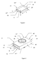
- Figure 3 is a schematic perspective view of another example of the disclosure.
- a specially designed sealing means (30) is fitted outside the flow cell (10) to provide a sealable flow cell (31).
- the single sealing means (30) provides sealing at both the inlet (16) and outlet (18) ends of the flow cell (10) and it also protects the potentially fragile flow cell (10) from breaking, if subjected to impacts or shocks during assembly or use.
- the sealing means (30) preferably covers all of the walls of the flow cell (10), except for at least one UV radiation transmission window (44).
- the sealing means (30) is preferably made of opaque material (in one embodiment SantopreneTM TPV 181-64MED, Exxon Mobile Chemical, USA), so that essentially no UV radiation, visible radiation or near infrared radiation can pass through the material. Accordingly, the amount of stray light entering the flow cell and thus the detector is minimised.
- the sealing means (30) is formed to fit outside the flow cell (10) described above.
- the sealing means (30) is typically formed as a housing defined by at least one wall (32), an inlet portion (34) intended to provide sealing around the inlet portion (16) of the flow cell (10) and an outlet portion (36) intended to provide sealing around the outlet portion (18) of the flow cell (10).
- the sealing means (30) is shown as having a cross section formed as a rectangle, but other cross-sectional shapes such as square, oval, circular, etc are conceivable, and encloses a chamber (38) defined by two pairs of walls (40', 40", 42', 42").
- the chamber (38) is designed to tightly enclose a flow cell (10) and seal around it.
- the two walls (40', 40", 42', 42") forming each pair are typically parallel and aligned to each other.
- the two pairs of walls are positioned at an angle of 90 degrees to each other, forming the chamber (38) of the sealing means (30).
- One pair of the walls preferably has one UV radiation transmission window (44) on each wall.
- the two windows (44) are positioned opposite each other in alignment, so that beams of UV radiation can pass through both windows.
- the windows can be of any geometrical shape.
- the windows (44) are preferably formed as circles.
- the sealable flow cell (31) shown in Figure 3 is shown having two UV radiation transmission windows (44), but the use of only one window (44) or more than two windows (44) is conceivable.
- the sealing means comprises a raised rim (46) around the UV radiation transmission window (44), to provide a structure which facilitates sealing the optical path into and out from the flow cell (10).
- the end faces of the flow cell (10) are not covered by the sealing means which allows simplified manufacturing of the flow cell/sealing means assembly.
- the exposed end faces of the flow cell (10) are also covered by the opaque sealing means as shown by dotted lines in Figure 3 .
- the wall (40'-42") of the sealing means (30) preferably has a thickness ⁇ 3mm, preferably ⁇ 1.5mm, more preferably ⁇ 1.0mm, even more preferably ⁇ 0.5mm.
- the sealing means (30) is preferably resilient, to facilitate sealing against the flow cell and other components of the system to which it is intended to be used.
- the sealing means (30) is preferably manufactured from a mouldable material. Further, the material of the sealing means (30) preferably fulfils the requirements for USP class VI materials. Even more preferably, the material of the sealing means (30) is a validated USP class VI material.
- the flow cell (10) and the sealing means (30) are manufactured as separate parts, for example by the use of moulding. However, it is of course also possible to produce the flow cell (10) and the sealing means (30) as a single part, for example by the use of sequential moulding.
- a sealable flow cell (31) according to the present disclosure can be manufactured by the use of moulding. Further, the sealable flow cell (31) according to the present disclosure can be manufactured by the use of injection moulding. The sealable flow cell (31) according to the present disclosure can also be manufactured by the use of extrusion. Further, the sealable flow cell (31) according to the present disclosure can be manufactured by the use of co-extrusion. The sealable flow cell (31) is preferably moulded in one single piece, but it is also possible to assemble the sealable flow cell (31) from several parts.
- Figure 4 is a schematic perspective exploded view demonstrating how an example of a sealable flow cell (31) according to the disclosure can be connected to liquid flow channels (50, 52).
- the sealable flow cell (31), comprising the flow cell (10) inside the sealing means (30), is easily inserted into the system to connect to the liquid flow channels (50, 52), without the use of regular sleeves and ferrules.
- the flow cell (10), inside the sealing means (30), can be connected by the use of holders (54, 56) to liquid flow channels (50, 52) as shown in Figure 4 .
- holders 54, 56
- the sealing means (30) enables the use of a UV detector that is open at one side.
- the flow cell can be exchanged without loosening of tubes by just sliding in the flow cell from the side. This is advantageous if the flow cell and the connecting liquid flow channel is sterilised as a whole.
- a flow cell according to the present disclosure is suitable for use in a method for measuring UV absorption of a sample. Further, a flow cell according to the present disclosure is suitable for use in a method for measuring UV absorption of a sample in a chromatography system or in a filtration system.
- the source of UV radiation can be any source of UV radiation known by the man skilled in the art. In one method for measuring UV absorption of a sample the UV energy is provided by a LED. Table 1.
- Estimation of the total intensity of UV radiation ( ⁇ 280 nm) hitting the flow cell, calculated from the equipment and the optical set-up used.
- UV-LED intensity 100 ⁇ W (+/- 50 ⁇ W)
- Transmission bandpass filter 18% transmitted Aperture: 2 mm diameter, original beam size 3x3 mm (rectangular shape): 35% transmitted Reflection loss lens: 8% (92% transmitted)
- Reflection loss beam splitter 40% (+/- 5 %), 60% transmitted Reflection loss window: 8% (92% transmitted)
- Total intensity hitting flow cell 3 ⁇ W, spot size approx. 5 mm 2 Table 3.
Landscapes
- Physics & Mathematics (AREA)
- Health & Medical Sciences (AREA)
- General Health & Medical Sciences (AREA)
- Chemical & Material Sciences (AREA)
- Life Sciences & Earth Sciences (AREA)
- Immunology (AREA)
- Biochemistry (AREA)
- General Physics & Mathematics (AREA)
- Analytical Chemistry (AREA)
- Pathology (AREA)
- Spectroscopy & Molecular Physics (AREA)
- Public Health (AREA)
- Epidemiology (AREA)
- Animal Behavior & Ethology (AREA)
- Veterinary Medicine (AREA)
- Chemical Kinetics & Catalysis (AREA)
- Organic Chemistry (AREA)
- Toxicology (AREA)
- Optical Measuring Cells (AREA)
Claims (13)
- Verfahren zum Messen einer UV-Absorption einer Probe unter Verwendung einer Durchflusszelle (10), umfassend einen Fluideinlass (16) und einen Fluidauslass (18), die durch eine Probendurchflusskammer (12) getrennt sind, umfassend mindestens ein UV-transparentes Fenster (22'), dadurch gekennzeichnet, dass das mindestens eine UV-transparente Fenster (22') aus einem Polymermaterial besteht und einer Gammastrahlungssterilisation unterzogen wurde.
- Verfahren nach Anspruch 1, dadurch gekennzeichnet, dass eine Dosis von mindestens 10 kGy für die Gammastrahlungssterilisation verwendet wird.
- Verfahren nach einem der Ansprüche 1 - 2, dadurch gekennzeichnet, dass das Polymermaterial eine UV-Durchlässigkeit im Bereich zwischen 1% und 40% bei einer Wellenlänge von 280 nm hat, nachdem es der Gammastrahlungssterilisation unterzogen wurde.
- Verfahren nach einem der Ansprüche 1 - 3, dadurch gekennzeichnet, dass die Durchlässigkeit des Polymermaterials, nachdem es der Gammastrahlungssterilisation unterzogen wurde, während einer Belichtung mit UV-Licht einer Intensität von etwa 0,6 µW/mm2 über eine Periode von 72 Stunden um nicht mehr als 10% schwankt.
- Verfahren nach einem der Ansprüche 1 - 3, dadurch gekennzeichnet, dass die Durchlässigkeit des Polymermaterials, nachdem es der Gammastrahlungssterilisation unterzogen wurde, während einer Belichtung mit UV-Licht einer Intensität von etwa 0,6 µW/mm2 über eine Periode von 48 Stunden um nicht mehr als 10% schwankt.
- Verfahren nach einem der Ansprüche 1 - 5, dadurch gekennzeichnet, dass die UV-Durchlässigkeit des Polymermaterials größer als 2% und kleiner als 30% pro mm ist, nachdem es der Gammastrahlungssterilisation unterzogen wurde.
- Verfahren nach einem der Ansprüche 1 - 6, dadurch gekennzeichnet, dass die UV-Durchlässigkeit des Polymermaterials größer als 5% und kleiner als 20% pro mm ist, nachdem es der Gammastrahlungssterilisation unterzogen wurde.
- Verfahren nach einem der Ansprüche 1 - 7, dadurch gekennzeichnet, dass die UV-Durchlässigkeit des Polymermaterials größer als 12% und kleiner als 18% pro mm ist, nachdem es der Gammastrahlungssterilisation unterzogen wurde.
- Verfahren nach einem der Ansprüche 1 - 8, dadurch gekennzeichnet, dass ein Dichtungsmittel (30) außerhalb der Durchflusszelle eingesetzt ist, um eine dicht verschließbare Durchflusszelle (31) bereitzustellen.
- Verfahren nach Anspruch 9, dadurch gekennzeichnet, dass das Dichtungsmittel aus einem undurchlässigen Material besteht, so dass im Wesentlichen keine UV-Strahlung, sichtbare Strahlung oder Nahinfrarotstrahlung durch das Material hindurch gehen kann, wobei das Dichtungsmittel zusätzlich ein UV-Strahlungsdurchlassfenster (44) umfasst.
- Verfahren nach einem der Ansprüche 1 bis 10, dadurch gekennzeichnet, dass es brennbar ist.
- Verfahren nach einem der Ansprüche 1 bis 11, dadurch gekennzeichnet, dass die UV-Strahlung durch eine oder mehrere Leuchtdiode(n) bereitgestellt wird.
- Kit von Teilen, umfassend
einen UV-Absorptionsdetektor, der an einer Seite offen ist, und
eine Durchflusszelle (10), umfassend einen Fluideinlass (16) und einen Fluidauslass (18), die durch eine Probendurchflusskammer (12) getrennt sind, umfassend mindestens ein UV-transparentes Fenster (22'),
wobei
das mindestens eine UV-transparente Fenster (22') aus einem Polymermaterial besteht und einer Gammastrahlungssterilisation unterzogen wurde.
Applications Claiming Priority (2)
| Application Number | Priority Date | Filing Date | Title |
|---|---|---|---|
| GBGB0703175.0A GB0703175D0 (en) | 2007-02-20 | 2007-02-20 | Polymeric device suitable for ultraviolet detection |
| PCT/EP2008/001168 WO2008101637A2 (en) | 2007-02-20 | 2008-02-15 | Polymeric device suitable for ultraviolet detection |
Publications (2)
| Publication Number | Publication Date |
|---|---|
| EP2113076A2 EP2113076A2 (de) | 2009-11-04 |
| EP2113076B1 true EP2113076B1 (de) | 2014-10-22 |
Family
ID=37908869
Family Applications (1)
| Application Number | Title | Priority Date | Filing Date |
|---|---|---|---|
| EP08715789.7A Active EP2113076B1 (de) | 2007-02-20 | 2008-02-15 | Für ultravioletterkennung geeignete polymere vorrichtung |
Country Status (7)
| Country | Link |
|---|---|
| US (4) | US20080212073A1 (de) |
| EP (1) | EP2113076B1 (de) |
| JP (1) | JP5180973B2 (de) |
| CN (1) | CN101611305B (de) |
| CA (1) | CA2676204A1 (de) |
| GB (2) | GB0703175D0 (de) |
| WO (1) | WO2008101637A2 (de) |
Families Citing this family (20)
| Publication number | Priority date | Publication date | Assignee | Title |
|---|---|---|---|---|
| US9575087B2 (en) | 2012-09-06 | 2017-02-21 | Parker-Hannifin Corporation | Risk-managed, single-use, pre-calibrated, pre-sterilized sensors for use in bio-processing applications |
| US11827875B2 (en) | 2006-08-02 | 2023-11-28 | Finesse Solutions, Inc. | Method for manufacturing a composite sensor |
| US10227555B2 (en) * | 2006-08-02 | 2019-03-12 | Finesse Solutions, Inc. | Composite sensor assemblies for single use bioreactors |
| GB0703175D0 (en) | 2007-02-20 | 2007-03-28 | Ge Healthcare Bio Sciences Ab | Polymeric device suitable for ultraviolet detection |
| GB0922426D0 (en) * | 2009-12-22 | 2010-02-03 | Ge Healthcare Bio Sciences Ab | Containers for chromatography media |
| DE102010038428A1 (de) | 2010-07-26 | 2012-01-26 | Endress + Hauser Conducta Gesellschaft für Mess- und Regeltechnik mbH + Co. KG | Optisches Messsystem |
| US20120119101A1 (en) * | 2010-11-12 | 2012-05-17 | Endress + Hauser Conducta Gesellschaft Fur Mess-Und Regeltechnik Mbh + Co. Kg | Miniature UV sensor utilizing a disposable flow cell |
| DE102011013001B4 (de) | 2011-03-04 | 2016-05-25 | Optek-Danulat Gmbh | Durchströmbare Messzelle zur Aufnahme von Messmitteln |
| US8817259B2 (en) | 2011-03-25 | 2014-08-26 | Parker-Hannifin Corporation | Optical sensors for monitoring biopharmaceutical solutions in single-use containers |
| US9525293B2 (en) | 2011-12-30 | 2016-12-20 | Makita Corporation | Battery charger having angled wall in battery receiving opening, and battery pack charging system and cordless power tool system including same |
| US9146192B2 (en) * | 2012-05-17 | 2015-09-29 | Wyatt Technology Corporation | Integrated light scattering and ultraviolet absorption measurement system |
| US20140011980A1 (en) * | 2012-07-03 | 2014-01-09 | Allergan, Inc. | Methods for sterilizing compositions and resulting compositions |
| DE102012108158B4 (de) * | 2012-09-03 | 2016-03-17 | Johann Wolfgang Goethe-Universität | Kapillarzelle, Anordnung und Verfahren zur Aufnahme, zur Positionierung und zur Untersuchung einer mikroskopischen Probe |
| US9781496B2 (en) | 2012-10-25 | 2017-10-03 | Milwaukee Electric Tool Corporation | Worksite audio device with wireless interface |
| US10119851B2 (en) | 2016-12-20 | 2018-11-06 | General Electric Company | Coriolis flow meter for measuring properties of a fluid and method therefor |
| EP3559610B1 (de) * | 2016-12-20 | 2024-09-25 | General Electric Company | Coriolis-durchflussmesser zur messung der eigenschaften eines fluids und verfahren dafür |
| CN110346461B (zh) * | 2018-04-03 | 2022-01-11 | 中国科学院大连化学物理研究所 | 一种光检测流通池 |
| DE102019132218B4 (de) * | 2019-11-27 | 2023-06-15 | MAX-PLANCK-Gesellschaft zur Förderung der Wissenschaften e.V. | Durchflussmesszelle |
| GB2611312B (en) * | 2021-09-29 | 2024-11-13 | Agilent Technologies Inc | Flow cell for sample separation apparatus with protection against electromagnetic stray radiation |
| US12023424B1 (en) | 2022-12-16 | 2024-07-02 | Myna Life Technologies, Inc. | Continuous disinfection of human occupied space |
Family Cites Families (34)
| Publication number | Priority date | Publication date | Assignee | Title |
|---|---|---|---|---|
| US3401591A (en) * | 1963-12-09 | 1968-09-17 | Warner Lambert Pharmaceutical | Analytical cuvette and supply system wherein the cuvette inlet and outlet are located on the bottom of the cuvette |
| US3327119A (en) * | 1964-03-26 | 1967-06-20 | Ibm | Method and apparatus for detecting cancer cells |
| US4008397A (en) * | 1975-04-24 | 1977-02-15 | Hoffmann-La Roche Inc. | Fluorometer flow cell |
| JPS63233374A (ja) * | 1987-03-20 | 1988-09-29 | Tohoku Denshi Sangyo Kk | 過酸化脂質の測定方法およびその測定装置 |
| JPS63315054A (ja) * | 1987-06-17 | 1988-12-22 | Takeshi Suzuki | 小児鍼 |
| JP2807287B2 (ja) * | 1989-10-13 | 1998-10-08 | 株式会社医学生物学研究所 | ペプチドおよびその用途 |
| JPH0477540A (ja) * | 1990-07-17 | 1992-03-11 | Idemitsu Petrochem Co Ltd | ポリプロピレン系樹脂組成物 |
| US5444807A (en) * | 1993-03-29 | 1995-08-22 | World Precision Instruments, Inc. | Micro chemical analysis employing flow through detectors |
| US6199257B1 (en) * | 1995-02-28 | 2001-03-13 | Thermo Separation Products, Inc. | Method of making a flow cell for light absorption measurement of small volume samples |
| US5674290A (en) * | 1995-04-05 | 1997-10-07 | Li; Shu-Tung | Water-stabilized biopolymeric implants |
| JPH09220214A (ja) * | 1996-02-20 | 1997-08-26 | Sekisui Chem Co Ltd | 細胞機能測定用反応器及び細胞機能測定用キット |
| US5885470A (en) * | 1997-04-14 | 1999-03-23 | Caliper Technologies Corporation | Controlled fluid transport in microfabricated polymeric substrates |
| JPH1038795A (ja) * | 1996-07-27 | 1998-02-13 | Horiba Ltd | 光学式流体分析装置 |
| JP3516400B2 (ja) * | 1997-05-20 | 2004-04-05 | ザイムクエスト,インク. | 細胞処理システム |
| US6130981A (en) | 1998-03-20 | 2000-10-10 | Polymicro Technologies, Llc | Gamma radiation sterilized fiber optic UV delivery systems |
| RU2145898C1 (ru) * | 1998-07-07 | 2000-02-27 | Иващенко Гаррий Дмитриевич | Устройство для экстракорпоральной обработки крови |
| US7068361B2 (en) * | 1999-06-03 | 2006-06-27 | Baxter International | Apparatus, systems and methods for processing and treating a biological fluid with light |
| DE60036385T2 (de) * | 1999-06-21 | 2008-06-26 | The General Hospital Corp., Boston | Zellkultursysteme und verfahren für einrichtungen zur organunterstützung |
| US6495351B2 (en) * | 2000-02-08 | 2002-12-17 | Gendel Limited | Loading system and method for using the same |
| GB0002856D0 (en) | 2000-02-08 | 2000-03-29 | Gendel Limited | Ultrasound sensitisation |
| CA2399452A1 (en) * | 2000-02-11 | 2001-08-16 | Proteosys Ag. | Use of neuregulin-.beta. as an indicator and/or target |
| WO2002029397A2 (en) | 2000-10-05 | 2002-04-11 | E.I. Du Pont De Nemours And Company | Polymeric microfabricated fluidic device suitable for ultraviolet detection |
| WO2002075284A2 (en) * | 2001-03-20 | 2002-09-26 | Abb Bomem Inc. | Flow-through cell |
| JP2004037409A (ja) * | 2002-07-08 | 2004-02-05 | Toagosei Co Ltd | 光吸収スペクトル分析用セル、及びそれを用いるシラノール基濃度の測定方法 |
| US20040142484A1 (en) * | 2002-09-30 | 2004-07-22 | Intel Corporation | Spectroscopic analysis system and method |
| US20040120848A1 (en) * | 2002-12-20 | 2004-06-24 | Maria Teodorczyk | Method for manufacturing a sterilized and calibrated biosensor-based medical device |
| JP4240466B2 (ja) * | 2003-05-30 | 2009-03-18 | 有限会社シマムラテック | 分取液体クロマトグラフィー用検出装置 |
| JP4236995B2 (ja) * | 2003-06-17 | 2009-03-11 | 三井化学株式会社 | ポリプロピレン樹脂組成物およびその用途 |
| JP4679847B2 (ja) * | 2004-07-12 | 2011-05-11 | オリンパス株式会社 | 細胞の解析方法 |
| US20060182664A1 (en) | 2005-02-14 | 2006-08-17 | Peck Bill J | Flow cell devices, systems and methods of using the same |
| US7277167B2 (en) * | 2005-09-13 | 2007-10-02 | Agilent Technologies, Inc. | Modular cuvettes and methods for use thereof |
| US20070081159A1 (en) * | 2005-10-11 | 2007-04-12 | Giffin Kristin M | Apparatus and methods for evaluating an optical property of a liquid sample |
| US7515259B2 (en) * | 2006-03-10 | 2009-04-07 | Dionex Corporation | Flow cell for optical detector and method of forming same |
| GB0703175D0 (en) | 2007-02-20 | 2007-03-28 | Ge Healthcare Bio Sciences Ab | Polymeric device suitable for ultraviolet detection |
-
2007
- 2007-02-20 GB GBGB0703175.0A patent/GB0703175D0/en not_active Ceased
-
2008
- 2008-02-15 WO PCT/EP2008/001168 patent/WO2008101637A2/en not_active Ceased
- 2008-02-15 CN CN2008800048959A patent/CN101611305B/zh active Active
- 2008-02-15 CA CA002676204A patent/CA2676204A1/en not_active Abandoned
- 2008-02-15 JP JP2009549377A patent/JP5180973B2/ja active Active
- 2008-02-15 GB GB0802836A patent/GB2446934A/en not_active Withdrawn
- 2008-02-15 US US12/032,197 patent/US20080212073A1/en not_active Abandoned
- 2008-02-15 EP EP08715789.7A patent/EP2113076B1/de active Active
-
2013
- 2013-05-10 US US13/891,340 patent/US9404862B2/en active Active
-
2016
- 2016-07-01 US US15/200,722 patent/US10094770B2/en active Active
-
2018
- 2018-09-13 US US16/130,100 patent/US10816459B2/en active Active
Also Published As
| Publication number | Publication date |
|---|---|
| CN101611305B (zh) | 2011-09-14 |
| WO2008101637A2 (en) | 2008-08-28 |
| US10816459B2 (en) | 2020-10-27 |
| US9404862B2 (en) | 2016-08-02 |
| US10094770B2 (en) | 2018-10-09 |
| JP2010519505A (ja) | 2010-06-03 |
| US20190011356A1 (en) | 2019-01-10 |
| JP5180973B2 (ja) | 2013-04-10 |
| US20130240747A1 (en) | 2013-09-19 |
| CN101611305A (zh) | 2009-12-23 |
| GB2446934A (en) | 2008-08-27 |
| US20160313240A1 (en) | 2016-10-27 |
| WO2008101637A3 (en) | 2008-10-30 |
| GB0703175D0 (en) | 2007-03-28 |
| US20080212073A1 (en) | 2008-09-04 |
| EP2113076A2 (de) | 2009-11-04 |
| CA2676204A1 (en) | 2008-08-28 |
| GB0802836D0 (en) | 2008-03-26 |
Similar Documents
| Publication | Publication Date | Title |
|---|---|---|
| EP2113076B1 (de) | Für ultravioletterkennung geeignete polymere vorrichtung | |
| US20230088857A1 (en) | Optical Sensors for Monitoring Biopharmaceutical Solutions in Single-Use Containers | |
| US5616923A (en) | Gas analyzer cuvettes | |
| US5693944A (en) | Gas analyzer cuvettes | |
| US20120119101A1 (en) | Miniature UV sensor utilizing a disposable flow cell | |
| CA2373673C (en) | Flow cytometer and ultraviolet light disinfecting systems | |
| US8493559B2 (en) | Cuvette | |
| US9222883B2 (en) | Optical measuring system having a cell holder to accommodate flow through cells of different dimensions in the direction of optical path | |
| US9346578B2 (en) | Aseptic connectors for bio-processing containers | |
| US20140346370A1 (en) | Reflective Transparent Optical Chamber | |
| US20050257885A1 (en) | Capillary multi-channel optical flow cell | |
| KR20220066161A (ko) | 유체의 단백질 농도 측정 | |
| US9146189B2 (en) | Optical cell with disposable fluid cartridge | |
| US20150338336A1 (en) | Reflective Transparent Optical Chamber | |
| WO2011159982A2 (en) | Scattering light source multi-wavelength photometer | |
| US20050117152A1 (en) | Optical device for simultaneous multiple measurement using polarimetry and spectrometry and method for regulating/monitoring physical-chemical and biotechnical processes using said device | |
| JP2010151510A (ja) | 液性測定装置 | |
| EP3889578A1 (de) | Durchflusszellenanordnung und spektroskopievorrichtungsanordnung zur verwendung in einem bioprozess | |
| Salih et al. | Fabrication and integration of PDMS-glass based microfluidic with optical absorbance measurement device for coliform bacteria detection | |
| JP6924452B2 (ja) | 光学測定システム及び光学セル |
Legal Events
| Date | Code | Title | Description |
|---|---|---|---|
| PUAI | Public reference made under article 153(3) epc to a published international application that has entered the european phase |
Free format text: ORIGINAL CODE: 0009012 |
|
| 17P | Request for examination filed |
Effective date: 20090604 |
|
| AK | Designated contracting states |
Kind code of ref document: A2 Designated state(s): AT BE BG CH CY CZ DE DK EE ES FI FR GB GR HR HU IE IS IT LI LT LU LV MC MT NL NO PL PT RO SE SI SK TR |
|
| 17Q | First examination report despatched |
Effective date: 20091216 |
|
| DAX | Request for extension of the european patent (deleted) | ||
| GRAP | Despatch of communication of intention to grant a patent |
Free format text: ORIGINAL CODE: EPIDOSNIGR1 |
|
| INTG | Intention to grant announced |
Effective date: 20140522 |
|
| GRAS | Grant fee paid |
Free format text: ORIGINAL CODE: EPIDOSNIGR3 |
|
| GRAA | (expected) grant |
Free format text: ORIGINAL CODE: 0009210 |
|
| AK | Designated contracting states |
Kind code of ref document: B1 Designated state(s): AT BE BG CH CY CZ DE DK EE ES FI FR GB GR HR HU IE IS IT LI LT LU LV MC MT NL NO PL PT RO SE SI SK TR |
|
| REG | Reference to a national code |
Ref country code: GB Ref legal event code: FG4D |
|
| REG | Reference to a national code |
Ref country code: CH Ref legal event code: EP |
|
| REG | Reference to a national code |
Ref country code: AT Ref legal event code: REF Ref document number: 692878 Country of ref document: AT Kind code of ref document: T Effective date: 20141115 |
|
| REG | Reference to a national code |
Ref country code: IE Ref legal event code: FG4D |
|
| REG | Reference to a national code |
Ref country code: DE Ref legal event code: R096 Ref document number: 602008034989 Country of ref document: DE Effective date: 20141204 |
|
| REG | Reference to a national code |
Ref country code: NL Ref legal event code: T3 |
|
| REG | Reference to a national code |
Ref country code: AT Ref legal event code: MK05 Ref document number: 692878 Country of ref document: AT Kind code of ref document: T Effective date: 20141022 |
|
| REG | Reference to a national code |
Ref country code: LT Ref legal event code: MG4D |
|
| PG25 | Lapsed in a contracting state [announced via postgrant information from national office to epo] |
Ref country code: PT Free format text: LAPSE BECAUSE OF FAILURE TO SUBMIT A TRANSLATION OF THE DESCRIPTION OR TO PAY THE FEE WITHIN THE PRESCRIBED TIME-LIMIT Effective date: 20150223 Ref country code: NO Free format text: LAPSE BECAUSE OF FAILURE TO SUBMIT A TRANSLATION OF THE DESCRIPTION OR TO PAY THE FEE WITHIN THE PRESCRIBED TIME-LIMIT Effective date: 20150122 Ref country code: ES Free format text: LAPSE BECAUSE OF FAILURE TO SUBMIT A TRANSLATION OF THE DESCRIPTION OR TO PAY THE FEE WITHIN THE PRESCRIBED TIME-LIMIT Effective date: 20141022 Ref country code: IS Free format text: LAPSE BECAUSE OF FAILURE TO SUBMIT A TRANSLATION OF THE DESCRIPTION OR TO PAY THE FEE WITHIN THE PRESCRIBED TIME-LIMIT Effective date: 20150222 Ref country code: FI Free format text: LAPSE BECAUSE OF FAILURE TO SUBMIT A TRANSLATION OF THE DESCRIPTION OR TO PAY THE FEE WITHIN THE PRESCRIBED TIME-LIMIT Effective date: 20141022 Ref country code: LT Free format text: LAPSE BECAUSE OF FAILURE TO SUBMIT A TRANSLATION OF THE DESCRIPTION OR TO PAY THE FEE WITHIN THE PRESCRIBED TIME-LIMIT Effective date: 20141022 |
|
| PG25 | Lapsed in a contracting state [announced via postgrant information from national office to epo] |
Ref country code: SE Free format text: LAPSE BECAUSE OF FAILURE TO SUBMIT A TRANSLATION OF THE DESCRIPTION OR TO PAY THE FEE WITHIN THE PRESCRIBED TIME-LIMIT Effective date: 20141022 Ref country code: HR Free format text: LAPSE BECAUSE OF FAILURE TO SUBMIT A TRANSLATION OF THE DESCRIPTION OR TO PAY THE FEE WITHIN THE PRESCRIBED TIME-LIMIT Effective date: 20141022 Ref country code: GR Free format text: LAPSE BECAUSE OF FAILURE TO SUBMIT A TRANSLATION OF THE DESCRIPTION OR TO PAY THE FEE WITHIN THE PRESCRIBED TIME-LIMIT Effective date: 20150123 Ref country code: PL Free format text: LAPSE BECAUSE OF FAILURE TO SUBMIT A TRANSLATION OF THE DESCRIPTION OR TO PAY THE FEE WITHIN THE PRESCRIBED TIME-LIMIT Effective date: 20141022 Ref country code: AT Free format text: LAPSE BECAUSE OF FAILURE TO SUBMIT A TRANSLATION OF THE DESCRIPTION OR TO PAY THE FEE WITHIN THE PRESCRIBED TIME-LIMIT Effective date: 20141022 Ref country code: LV Free format text: LAPSE BECAUSE OF FAILURE TO SUBMIT A TRANSLATION OF THE DESCRIPTION OR TO PAY THE FEE WITHIN THE PRESCRIBED TIME-LIMIT Effective date: 20141022 Ref country code: CY Free format text: LAPSE BECAUSE OF FAILURE TO SUBMIT A TRANSLATION OF THE DESCRIPTION OR TO PAY THE FEE WITHIN THE PRESCRIBED TIME-LIMIT Effective date: 20141022 |
|
| REG | Reference to a national code |
Ref country code: DE Ref legal event code: R097 Ref document number: 602008034989 Country of ref document: DE |
|
| PG25 | Lapsed in a contracting state [announced via postgrant information from national office to epo] |
Ref country code: CZ Free format text: LAPSE BECAUSE OF FAILURE TO SUBMIT A TRANSLATION OF THE DESCRIPTION OR TO PAY THE FEE WITHIN THE PRESCRIBED TIME-LIMIT Effective date: 20141022 Ref country code: DK Free format text: LAPSE BECAUSE OF FAILURE TO SUBMIT A TRANSLATION OF THE DESCRIPTION OR TO PAY THE FEE WITHIN THE PRESCRIBED TIME-LIMIT Effective date: 20141022 Ref country code: RO Free format text: LAPSE BECAUSE OF FAILURE TO SUBMIT A TRANSLATION OF THE DESCRIPTION OR TO PAY THE FEE WITHIN THE PRESCRIBED TIME-LIMIT Effective date: 20141022 Ref country code: EE Free format text: LAPSE BECAUSE OF FAILURE TO SUBMIT A TRANSLATION OF THE DESCRIPTION OR TO PAY THE FEE WITHIN THE PRESCRIBED TIME-LIMIT Effective date: 20141022 Ref country code: SK Free format text: LAPSE BECAUSE OF FAILURE TO SUBMIT A TRANSLATION OF THE DESCRIPTION OR TO PAY THE FEE WITHIN THE PRESCRIBED TIME-LIMIT Effective date: 20141022 |
|
| PLBE | No opposition filed within time limit |
Free format text: ORIGINAL CODE: 0009261 |
|
| STAA | Information on the status of an ep patent application or granted ep patent |
Free format text: STATUS: NO OPPOSITION FILED WITHIN TIME LIMIT |
|
| PG25 | Lapsed in a contracting state [announced via postgrant information from national office to epo] |
Ref country code: IT Free format text: LAPSE BECAUSE OF FAILURE TO SUBMIT A TRANSLATION OF THE DESCRIPTION OR TO PAY THE FEE WITHIN THE PRESCRIBED TIME-LIMIT Effective date: 20141022 |
|
| 26N | No opposition filed |
Effective date: 20150723 |
|
| PG25 | Lapsed in a contracting state [announced via postgrant information from national office to epo] |
Ref country code: LU Free format text: LAPSE BECAUSE OF FAILURE TO SUBMIT A TRANSLATION OF THE DESCRIPTION OR TO PAY THE FEE WITHIN THE PRESCRIBED TIME-LIMIT Effective date: 20150215 |
|
| REG | Reference to a national code |
Ref country code: CH Ref legal event code: PL |
|
| PG25 | Lapsed in a contracting state [announced via postgrant information from national office to epo] |
Ref country code: MC Free format text: LAPSE BECAUSE OF FAILURE TO SUBMIT A TRANSLATION OF THE DESCRIPTION OR TO PAY THE FEE WITHIN THE PRESCRIBED TIME-LIMIT Effective date: 20141022 Ref country code: LI Free format text: LAPSE BECAUSE OF NON-PAYMENT OF DUE FEES Effective date: 20150228 Ref country code: CH Free format text: LAPSE BECAUSE OF NON-PAYMENT OF DUE FEES Effective date: 20150228 |
|
| REG | Reference to a national code |
Ref country code: IE Ref legal event code: MM4A |
|
| PG25 | Lapsed in a contracting state [announced via postgrant information from national office to epo] |
Ref country code: IE Free format text: LAPSE BECAUSE OF NON-PAYMENT OF DUE FEES Effective date: 20150215 |
|
| REG | Reference to a national code |
Ref country code: FR Ref legal event code: PLFP Year of fee payment: 9 |
|
| PG25 | Lapsed in a contracting state [announced via postgrant information from national office to epo] |
Ref country code: SI Free format text: LAPSE BECAUSE OF FAILURE TO SUBMIT A TRANSLATION OF THE DESCRIPTION OR TO PAY THE FEE WITHIN THE PRESCRIBED TIME-LIMIT Effective date: 20141022 |
|
| PG25 | Lapsed in a contracting state [announced via postgrant information from national office to epo] |
Ref country code: MT Free format text: LAPSE BECAUSE OF FAILURE TO SUBMIT A TRANSLATION OF THE DESCRIPTION OR TO PAY THE FEE WITHIN THE PRESCRIBED TIME-LIMIT Effective date: 20141022 |
|
| REG | Reference to a national code |
Ref country code: FR Ref legal event code: PLFP Year of fee payment: 10 |
|
| PG25 | Lapsed in a contracting state [announced via postgrant information from national office to epo] |
Ref country code: BG Free format text: LAPSE BECAUSE OF FAILURE TO SUBMIT A TRANSLATION OF THE DESCRIPTION OR TO PAY THE FEE WITHIN THE PRESCRIBED TIME-LIMIT Effective date: 20141022 Ref country code: HU Free format text: LAPSE BECAUSE OF FAILURE TO SUBMIT A TRANSLATION OF THE DESCRIPTION OR TO PAY THE FEE WITHIN THE PRESCRIBED TIME-LIMIT; INVALID AB INITIO Effective date: 20080215 |
|
| PG25 | Lapsed in a contracting state [announced via postgrant information from national office to epo] |
Ref country code: TR Free format text: LAPSE BECAUSE OF FAILURE TO SUBMIT A TRANSLATION OF THE DESCRIPTION OR TO PAY THE FEE WITHIN THE PRESCRIBED TIME-LIMIT Effective date: 20141022 |
|
| PG25 | Lapsed in a contracting state [announced via postgrant information from national office to epo] |
Ref country code: BE Free format text: LAPSE BECAUSE OF FAILURE TO SUBMIT A TRANSLATION OF THE DESCRIPTION OR TO PAY THE FEE WITHIN THE PRESCRIBED TIME-LIMIT Effective date: 20141022 |
|
| REG | Reference to a national code |
Ref country code: FR Ref legal event code: PLFP Year of fee payment: 11 |
|
| REG | Reference to a national code |
Ref country code: DE Ref legal event code: R081 Ref document number: 602008034989 Country of ref document: DE Owner name: CYTIVA SWEDEN AB, SE Free format text: FORMER OWNER: GE HEALTHCARE BIO-SCIENCES AB, UPPSALA, SE |
|
| REG | Reference to a national code |
Ref country code: NL Ref legal event code: HC Owner name: CYTIVA SWEDEN AB; SE Free format text: DETAILS ASSIGNMENT: CHANGE OF OWNER(S), CHANGE OF OWNER(S) NAME Effective date: 20210114 |
|
| P01 | Opt-out of the competence of the unified patent court (upc) registered |
Effective date: 20230526 |
|
| PGFP | Annual fee paid to national office [announced via postgrant information from national office to epo] |
Ref country code: NL Payment date: 20260220 Year of fee payment: 19 |
|
| PGFP | Annual fee paid to national office [announced via postgrant information from national office to epo] |
Ref country code: GB Payment date: 20260223 Year of fee payment: 19 |
|
| PGFP | Annual fee paid to national office [announced via postgrant information from national office to epo] |
Ref country code: DE Payment date: 20260220 Year of fee payment: 19 |
|
| PGFP | Annual fee paid to national office [announced via postgrant information from national office to epo] |
Ref country code: FR Payment date: 20260227 Year of fee payment: 19 |