EP2112055A1 - Luftleitbauteil und Karosserievorbau eines Kraftfahrzeuges - Google Patents
Luftleitbauteil und Karosserievorbau eines Kraftfahrzeuges Download PDFInfo
- Publication number
- EP2112055A1 EP2112055A1 EP09002806A EP09002806A EP2112055A1 EP 2112055 A1 EP2112055 A1 EP 2112055A1 EP 09002806 A EP09002806 A EP 09002806A EP 09002806 A EP09002806 A EP 09002806A EP 2112055 A1 EP2112055 A1 EP 2112055A1
- Authority
- EP
- European Patent Office
- Prior art keywords
- projections
- stem
- recesses
- mounting surface
- air guide
- Prior art date
- Legal status (The legal status is an assumption and is not a legal conclusion. Google has not performed a legal analysis and makes no representation as to the accuracy of the status listed.)
- Granted
Links
Images


Classifications
-
- B—PERFORMING OPERATIONS; TRANSPORTING
- B62—LAND VEHICLES FOR TRAVELLING OTHERWISE THAN ON RAILS
- B62D—MOTOR VEHICLES; TRAILERS
- B62D35/00—Vehicle bodies characterised by streamlining
- B62D35/005—Front spoilers
-
- F—MECHANICAL ENGINEERING; LIGHTING; HEATING; WEAPONS; BLASTING
- F16—ENGINEERING ELEMENTS AND UNITS; GENERAL MEASURES FOR PRODUCING AND MAINTAINING EFFECTIVE FUNCTIONING OF MACHINES OR INSTALLATIONS; THERMAL INSULATION IN GENERAL
- F16B—DEVICES FOR FASTENING OR SECURING CONSTRUCTIONAL ELEMENTS OR MACHINE PARTS TOGETHER, e.g. NAILS, BOLTS, CIRCLIPS, CLAMPS, CLIPS OR WEDGES; JOINTS OR JOINTING
- F16B5/00—Joining sheets or plates, e.g. panels, to one another or to strips or bars parallel to them
- F16B5/07—Joining sheets or plates, e.g. panels, to one another or to strips or bars parallel to them by means of multiple interengaging protrusions on the surfaces, e.g. hooks, coils
-
- Y—GENERAL TAGGING OF NEW TECHNOLOGICAL DEVELOPMENTS; GENERAL TAGGING OF CROSS-SECTIONAL TECHNOLOGIES SPANNING OVER SEVERAL SECTIONS OF THE IPC; TECHNICAL SUBJECTS COVERED BY FORMER USPC CROSS-REFERENCE ART COLLECTIONS [XRACs] AND DIGESTS
- Y02—TECHNOLOGIES OR APPLICATIONS FOR MITIGATION OR ADAPTATION AGAINST CLIMATE CHANGE
- Y02T—CLIMATE CHANGE MITIGATION TECHNOLOGIES RELATED TO TRANSPORTATION
- Y02T10/00—Road transport of goods or passengers
- Y02T10/80—Technologies aiming to reduce greenhouse gasses emissions common to all road transportation technologies
- Y02T10/82—Elements for improving aerodynamics
-
- Y—GENERAL TAGGING OF NEW TECHNOLOGICAL DEVELOPMENTS; GENERAL TAGGING OF CROSS-SECTIONAL TECHNOLOGIES SPANNING OVER SEVERAL SECTIONS OF THE IPC; TECHNICAL SUBJECTS COVERED BY FORMER USPC CROSS-REFERENCE ART COLLECTIONS [XRACs] AND DIGESTS
- Y10—TECHNICAL SUBJECTS COVERED BY FORMER USPC
- Y10T—TECHNICAL SUBJECTS COVERED BY FORMER US CLASSIFICATION
- Y10T403/00—Joints and connections
- Y10T403/70—Interfitted members
- Y10T403/7062—Clamped members
- Y10T403/7064—Clamped members by wedge or cam
Definitions
- the invention relates to an air guiding component of a motor vehicle, with hook-shaped projections, which are set up by their shape and arrangement to be inserted into recesses of a bodywork stem of the motor vehicle.
- the invention furthermore relates to a body stem arranged for mounting an air-conducting component, which has recesses which, by their shape and arrangement, are adapted to receive projections of the air-conducting component.
- the air-conducting component is a front spoiler which is fastened to a bumper fascia on the bow of the motor vehicle body.
- Such an air guide component and such a body stem is respectively from the US 2004/0135383 known.
- guiding and mounting areas of a front spoiler by a transverse to the direction of travel groove (spoiler mount groove) of the body front (front bumper) are recorded and held.
- the spoiler has a transverse to the direction of travel structure (fitting base section), which lies positively in the groove. Both the groove and the structure have a conical cross-section which limits an insertion of the spoiler into the groove against the direction of travel.
- the spoiler also has in the vehicle longitudinal direction to the rear facing mounting areas (insert / mount section), which engage deeper into the groove.
- Each attachment area carries a resilient latching / fixing section, which engages behind the groove through an upper inner edge of the groove and thus secures the spoiler against pulling out in the vehicle longitudinal direction.
- Additional fasteners such as grommets and / or clips grab by itself Covering holes in the attachment areas of the spoiler and a lower part of the body stem through and hold spoiler and body stem together.
- the object of the invention is to provide a fastening concept that allows a simpler and thus both time and cost-saving assembly and disassembly of a Luftleitbauteils. In addition, no tools should be required during assembly and disassembly.
- the air guiding component is applied with its mounting surface on the outside of the stem so that the protruding from the mounting surface projections engage in the recesses of the stem. Subsequently, the air guide member is moved transversely to a longitudinal axis of the motor vehicle, wherein the projections are displaced within the recesses until each projection in the assembled state engages behind an edge of the recess on an inner side of the stem opposite the mounting surface through the recess.
- the assembly is thus carried out essentially by a single transverse displacement of the suitably applied to the outside of the bodywork front spoiler member, without subsequently further fasteners such as rivets, screws or clips must be used.
- the shows Fig. 1 a middle portion of an air guiding member 10 together with a middle portion of a body stem 12 to which the air guiding member 10 is attached.
- the x-direction is parallel to the vehicle's longitudinal axis and points to the rear of the motor vehicle.
- the y-direction points to the right side of the motor vehicle and the z-direction is parallel to the vertical axis of the motor vehicle and points away from the roadway.
- Such an orientation of the air guiding component is characteristic of a front spoiler as an air guiding component 10.
- the air guide member 10 hook-shaped projections 14.1, 14.2, which are adapted by its shape and arrangement to be inserted into recesses 16.1, 16.2 of the bodywork stem 12, wherein the insertion takes place initially in the z-direction.
- the air guiding component 10 has a mounting surface 18, which is configured to rest against an outside 20 of the stem 12 in the mounted state of the air guiding component 10.
- the projections 14.1, 14.2 protrude from the mounting surface 18.
- the bodywork stem 12 is set up correspondingly for mounting the air-conducting component 10, wherein, in particular, the recesses 16.1, 16.2 are arranged by their shape and arrangement to receive the projections 14.1, 14.2 of the air-conducting component 10.
- the body stem 12 is in one embodiment, a bumper fascia of the motor vehicle.
- Each recess 16.1, 16.2 has a first region 22 with a larger clear width W1 and a second region 24 with a smaller clear width W2.
- the larger inside width W1 is matched to dimensions of the projections 14.1, 14.2 of the air-conducting component 10 such that the first regions 22 receive the projections 14.1, 14.2 on application of the mounting surface 18 of the air-conducting component 10 to the outside 20 of the stem 12, or that the projections in the z-direction in the recess in question and can be pushed.
- the smaller clear width W2 is matched to dimensions of the projections 14.1, 14.2 of the air-conducting component 10 such that they push in the projections 14.1, 14.2 from the first region 22 into the second region 24 along a direction of insertion E allowed, wherein the projections 14.1, 14.2 engage behind an edge 26 of the second portion 24 of the recess 16.1, 16.2 positively in the inserted state.
- the first regions 22 and the second regions 24 are preferably arranged side by side transversely to the vehicle longitudinal axis, wherein the transition from the first clear width W1 to the second clear width W2 takes place in a single stage.
- An alternative preferred embodiment provides that the transition from the first clear width W1 to the second clear width W2 is ramped.
- the fastening of the air guiding component 10 to the stem 12 is effected by applying the mounting surface 18 to the outside 20, wherein the application is made so that the projections 14.1, 14.2 are received by the first portions 22 of the receptacles 16.1, 16.2. Subsequently, the air guiding component 10 is displaced in the insertion direction E, which essentially corresponds to the vehicle transverse direction y, up to a stop.
- the air guiding component 10 is displaced in the insertion direction E, which essentially corresponds to the vehicle transverse direction y, up to a stop.
- projections and receptacles are coordinated with one another in such a way that the hooking takes place gradually, more or less in the manner of a zipper. This has the advantage that the worker no longer has to hold on to the already caught area.
- latching means which are arranged in the lateral end regions of the air guiding component 1o and the stem 12 and which are described below with reference to FIGS Figures 2 and 3 will be explained in more detail.
- the dimensions of the projections 14.1, 14.2 are matched to dimensions of the recesses 16.1, 16.2 of the stem 12 so that each projection 14.1, 14.2 in the assembled state, the edge 26 of the recess 16.1, 16.2 one of the mounting surface 18 opposite inner side 28 of the stem 12 by the recess 16.1, 16.2 engages behind.
- the shape and arrangement of the projections 14.1, 14.2 is also tuned to the shape and arrangement of the recesses 17.1, 16.2, that a transversely to a longitudinal axis of the motor vehicle successful insertion of the projections in the recesses is possible.
- the projection 16.1 is arranged in a parallel to the vehicle longitudinal direction distance d to the projection 16.2.
- a preferred embodiment is characterized by further, distributed over the mounting surface in the y-direction projections of which a first subset in the direction of travel at the front of the Lucasleitbauteil 10 and a second subset by a distance d to the rear offset on the mounting surface 18 is arranged.
- a further embodiment provides that in the y-direction a respective projection 16.2 follows from the second subset to a projection 16.1 from the first subset, so that there is a mutual arrangement of the projections.
- the Luftleitbauteil 10 consists of two firmly connected parts 30, 32 with different stiffness.
- the intended for attachment to the stem 12 part 30 is stiffer than the more compliant part 32.
- the stiffer part 30, which consists in one embodiment of polypropylene a viable, even high driving wind loads maintenance-retaining is achieved.
- the resilient part 32 which in one embodiment consists of a thermoplastic elastomer, the so-called hardness bending angle is increased. Damage at Light contacts with obstacles such as curbs are thereby avoided and / or reduced.
- the Fig. 2 shows a first lateral end portion 34 of an embodiment of an air guide member 10, wherein a projection 14.3 is aligned in the first lateral end portion 34 transverse to the insertion direction E and forms a stop for the transverse to the vehicle longitudinal direction -x insertion takes place.
- Other projections 14.5 and 14.6 correspond to the shape and function of the projections 14.1 and 14.2 from the Fig. 1 and differ essentially only from their arrangement and dimensions.
- the same reference numerals in the figures designate the same elements in their function, even if dimensions and arrangement are different.
- the Fig. 3 shows a plan view of an inner side 28 of the bodywork stem 12 with a first end portion 34 opposite the second end portion 36 of the Heilleitbauteils 10 in the assembled state.
- the second end portion 36 has a latching nose 38, which engages behind an edge of the stem 12 in the assembled state of the air guiding component 10.
- the part 30 of the Lucasleitbauteils 10 which has the comparatively higher stiffness, a predetermined bending point, which allows the non-destructive, taking place in the z-direction pivoting the locking lug in the stem 12.
- projections 14.7 and 14.8 correspond to the shape and function of the projections 14.1 and 14.2 from the Fig. 1 and differ essentially only from their arrangement and dimensions.
Landscapes
- Engineering & Computer Science (AREA)
- Mechanical Engineering (AREA)
- General Engineering & Computer Science (AREA)
- Chemical & Material Sciences (AREA)
- Combustion & Propulsion (AREA)
- Transportation (AREA)
- Connection Of Plates (AREA)
- Motor Or Generator Frames (AREA)
- Body Structure For Vehicles (AREA)
- Non-Portable Lighting Devices Or Systems Thereof (AREA)
Abstract
Description
- Die Erfindung betrifft ein Luftleitbauteil eines Kraftfahrzeugs, mit hakenförmigen Vorsprüngen, die durch ihre Form und Anordnung dazu eingerichtet sind, in Ausnehmungen eines Karosserievorbaus des Kraftfahrzeugs eingeschoben zu werden. Die Erfindung betrifft darüber hinaus einen zur Montage eines Luftleitbauteils eingerichteten Karosserievorbau, der Ausnehmungen aufweist, die durch ihre Form und Anordnung dazu eingerichtet sind, Vorsprünge des Luftleitbauteils aufzunehmen.
- Bei dem Luftleitbauteil handelt es sich in einer Ausgestaltung um einen Frontspoiler, der an einer Stoßfängerverkleidung am Bug der Kraftfahrzeugkarosserie befestigt wird.
- Ein solches Luftleitbauteil und ein solcher Karosserievorbau ist jeweils aus der
US 2004/0135383 bekannt. Nach dieser Schrift werden Führungs- und Befestigungsbereiche eines Frontspoilers durch eine quer zur Fahrtrichtung verlaufende Nut (spoiler mount groove) des Karosserievorbaus (front bumper) aufgenommen und gehalten. Der Spoiler weist eine quer zur Fahrtrichtung verlaufende Struktur (fitting base section) auf, die formschlüssig in der Nut liegt. Sowohl die Nut als auch die Struktur besitzen einen konischen Querschnitt, der ein gegen die Fahrtrichtung erfolgendes Einschieben des Spoilers in die Nut begrenzt. Zur Befestigung weist der Spoiler ferner in Fahrzeuglängsrichtung nach hinten weisende Befestigungsbereiche (insert/mount section) auf, die tiefer in die Nut eingreifen. Jeder Befestigungsbereich trägt einen federnden Riegel (latching/fixing section), der durch die Nut hindurch eine obere Innenkante der Nut hintergreift und den Spoiler damit gegen ein Hinausziehen in Fahrzeuglängsrichtung sichert. Zusätzliche Befestigungselemente wie Tüllen und/oder Clips greifen durch sich überdeckende Löcher in den Befestigungsbereichen des Spoilers und einem Unterteil des Karosserievorbaus hindurch und halten Spoiler und Karosserievorbau zusammen.
Zur Montage wird der Spoiler in einem ersten Schritt in die Nut eingeschoben und dabei durch die federnden Riegel in einer Montagestellung vorläufig fixiert. In einem zweiten Schritt erfolgt die weitere Befestigung durch Einsetzen der Befestigungselemente. - Die Aufgabe der Erfindung besteht in der Angabe eines Befestigungskonzeptes, das eine einfachere und damit sowohl Zeit als auch Kosten sparende Montage und Demontage eines Luftleitbauteils ermöglicht. Zudem sollen bei der Montage und Demontage keine Werkzeuge erforderlich sein.
- Diese Aufgabe wird jeweils mit den Merkmalen der unabhängigen Ansprüche gelöst.
- Zur Montage wird das Luftleitbauteil mit seiner Montagefläche an die Außenseite des Vorbaus so angelegt, dass die aus der Montagefläche aufragenden Vorsprünge in die Ausnehmungen des Vorbaus eingreifen. Anschließend wird das Luftleitbauteil quer zu einer Längsachse des Kraftfahrzeugs verschoben, wobei die Vorsprünge innerhalb der Ausnehmungen verschoben werden, bis jeder Vorsprung im montierten Zustand einen Rand der Ausnehmung auf einer der Montagefläche gegenüberliegenden Innenseite des Vorbaus durch die Ausnehmung hindurch hintergreift. Die Montage erfolgt damit im Wesentlichen durch eine einzige Querverschiebung des passend an die Außenseite des Karosserievorbaus angelegten Luftleitbauteils, ohne dass anschließend weitere Befestigungselemente wie Nieten, Schrauben oder Clips verwendet werden müssen.
- Dadurch wird die Zahl der benötigten Teile und Montagebewegungen, seien es Handgriffe eines Monteurs oder maschinell erfolgende Arbeitsschritte eines Fertigungsroboters, reduziert. Ein großer Vorteil ergibt sich ferner dadurch, dass das Luftleitbauteil durch eine umgekehrte erfolgende Demontagebewegung leicht demontierbar ist, was die Zeitersparnis im Reparaturfall im entsprechend vergrößert.
- Weitere Vorteile ergeben sich aus den abhängigen Ansprüchen, der Beschreibung und den beigefügten Figuren.
- Es versteht sich, dass die vorstehend genannten und die nachstehend noch zu erläuternden Merkmale nicht nur in der jeweils angegebenen Kombination, sondern auch in anderen Kombinationen oder in Alleinstellung verwendbar sind, ohne den Rahmen der vorliegenden Erfindung zu verlassen.
- Ausführungsbeispiele der Erfindung sind in den Zeichnungen dargestellt und werden in der nachfolgenden Beschreibung näher erläutert. Es zeigen, jeweils in schematischer Form:
- Fig. 1
- eine perspektivische Darstellung von Bereichen eines Luftleitbauteils und eines Kraftfahrzeugvorbaus im nicht montierten Zustand;
- Fig. 2
- eine Draufsicht auf einen ersten Endbereich des Luftleitbauteils; und
- Fig. 3
- eine Draufsicht auf eine Innenseite des Karosserievorbaus mit einem dem ersten Endbereich gegenüberliegenden zweiten Endbereich des Luftleitbauteils im montierten Zustand.
- Im Einzelnen zeigt die
Fig. 1 einen mittleren Bereich eines Luftleitbauteils 10 zusammen mit einem mittleren Bereich eines Karosserievorbaus 12, an dem das Luftleitbauteil 10 befestigt wird. Die x-Richtung ist zur Fahrzeuglängsachse parallel und weist zum Heck des Kraftfahrzeugs. Die y-Richtung weist zur rechten Seite des Kraftfahrzeugs und die z-Richtung liegt parallel zur Hochachse des Kraftfahrzeugs und weist von der Fahrbahn weg. Eine solche Ausrichtung des Luftleitbauteils ist für einen Frontspoiler als Luftleitbauteil 10 charakteristisch. - Zur Befestigung an dem Karosserievorbau 12 weist das Luftleitbauteil 10 hakenförmige Vorsprünge 14.1, 14.2 auf, die durch ihre Form und Anordnung dazu eingerichtet sind, in Ausnehmungen 16.1, 16.2 des Karosserievorbaus 12 eingeschoben zu werden, wobei das Einschieben zunächst in z-Richtung erfolgt. Das Luftleitbauteil 10 weist eine Montagefläche 18 auf, die dazu ausgestaltet ist, im montierten Zustand des Luftleitbauteils 10 an einer Außenseite 20 des Vorbaus 12 anzuliegen. Die Vorsprünge 14.1, 14.2 ragen aus der Montagefläche 18 auf.
- Der Karosserievorbau 12 ist entsprechend zur Montage des Luftleitbauteils 10 eingerichtet, wobei insbesondere die Ausnehmungen 16.1, 16.2 durch ihre Form und Anordnung dazu eingerichtet sind, die Vorsprünge 14.1, 14.2 des Luftleitbauteils 10 aufzunehmen. Der Karosserievorbau 12 ist in einer Ausgestaltung eine Stoßfängerverkleidung des Kraftfahrzeugs.
- Jede Ausnehmung 16.1, 16.2 weist einen ersten Bereich 22 mit einer größeren lichten Weite W1 und einen zweiten Bereich 24 mit einer kleineren lichten Weite W2 auf. Die größere lichte Weite W1 ist so auf Abmessungen der Vorsprünge 14.1, 14.2 des Luftleitbauteils 10 abgestimmt, dass die ersten Bereiche 22 die Vorsprünge 14.1, 14.2 beim Anlegen der Montagefläche 18 des Luftleitbauteils 10 an die Außenseite 20 des Vorbaus 12 aufnehmen, beziehungsweise dass die Vorsprünge in z-Richtung in die betreffende Ausnehmung hinein und hindurch geschoben werden kann. Die kleinere lichte Weite W2 ist so auf Abmessungen der Vorsprünge 14.1, 14.2 des Luftleitbauteils 10 abgestimmt, dass sie ein Einschieben der Vorsprünge 14.1, 14.2 aus dem ersten Bereich 22 in den zweiten Bereich 24 längs einer Einschieberichtung E erlaubt, wobei die Vorsprünge 14.1, 14.2 einen Rand 26 des zweiten Bereichs 24 der Ausnehmung 16.1, 16.2 im eingeschobenen Zustand formschlüssig hintergreifen.
- Die ersten Bereiche 22 und die zweiten Bereiche 24 sind bevorzugt quer zur Fahrzeuglängsachse nebeneinander angeordnet, wobei der Übergang von der ersten lichten Weite W1 auf die zweite lichte Weite W2 in einer einzigen Stufe erfolgt. Eine alternativ bevorzugte Ausgestaltung sieht vor, dass der Übergang von der ersten lichten Weite W1 auf die zweite lichte Weite W2 rampenförmig erfolgt.
- Die Befestigung des Luftleitbauteils 10 an dem Vorbau 12 erfolgt durch Anlegen der Montagefläche 18 an die Außenseite 20, wobei das Anlegen so erfolgt, dass die Vorsprünge 14.1, 14.2 durch die ersten Bereiche 22 der Aufnahmen 16.1, 16.2 aufgenommen werden. Anschließend wird das Luftleitbauteil 10 in der Einschieberichtung E, die im Wesentlichen der Fahrzeugquerrichtung y entspricht, bis zu einem Anschlag verschoben. Bei großer Länge des Luftleitbauteils kann es hilfreich sein, wenn Vorsprünge und Aufnahmen so aufeinander abgestimmt sind, dass das Verhaken nach und nach, quasi nach Art eines Reißverschlusses, erfolgt. Das hat den Vorteil, dass der Werker den bereits verhakten Bereich nicht mehr festhalten muss.
- Eine Sicherung gegen ein späteres unbeabsichtigtes Verschieben erfolgt durch Rastmittel, die in seitlichen Endbereichen von Luftleitbauteil 1o und Vorbau 12 angeordnet sind und die weiter unten mit Bezug auf die
Figuren 2 und3 noch näher erläutert werden. - Die Abmessungen der Vorsprünge 14.1, 14.2 sind auf Abmessungen der Ausnehmungen 16.1, 16.2 des Vorbaus 12 so abgestimmt, dass jeder Vorsprung 14.1, 14.2 im montierten Zustand den Rand 26 der Ausnehmung 16.1, 16.2 auf einer der Montagefläche 18 gegenüberliegenden Innenseite 28 des Vorbaus 12 durch die Ausnehmung 16.1, 16.2 hindurch hintergreift. Die Form und Anordnung der Vorsprünge 14.1, 14. 2 ist darüber hinaus so auf die Form und Anordnung der Ausnehmungen 17.1, 16.2 abgestimmt, dass ein quer zu einer Längsachse des Kraftfahrzeugs erfolgendes Einschieben der Vorsprünge in die Ausnehmungen möglich ist.
- In der in der
Fig. 1 dargestellten Ausgestaltung ist der Vorsprung 16.1 in einem zur Fahrzeuglängsrichtung parallelen Abstand d zu dem Vorsprung 16.2 angeordnet. Eine bevorzugte Ausgestaltung zeichnet sich durch weitere, über die Montagefläche in y-Richtung verteilte Vorsprünge aus, von denen eine erste Teilmenge in Fahrtrichtung vorne am Luftleitbauteil 10 und eine zweite Teilmenge um einen Abstand d nach hinten versetzt auf den Montagefläche 18 angeordnet ist. Eine weitere Ausgestaltung sieht vor, dass in y-Richtung je ein Vorsprung 16.2 aus der zweiten Teilmenge auf einen Vorsprung 16.1 aus der ersten Teilmenge folgt, so dass sich eine wechselseitige Anordnung der Vorsprünge ergibt. - Durch die wechselseitige Anordnung der Vorsprünge 14.1, 14.2 wird ein Aufspreizen erreicht, das eine Kraftaufnahme sowohl in Fahrtrichtung ( -x) als auch gegen die Fahrtrichtung, also in x-Richtung , ermöglicht.
- In der Ausgestaltung, die in der
Fig. 1 dargestellt ist, besteht das Luftleitbauteil 10 aus zwei miteinander fest verbundenen Teilen 30, 32 mit unterschiedlicher Steifigkeit. Das für die Befestigung an dem Vorbau 12 vorgesehene Teil 30 ist dabei steifer als das eher nachgiebige Teil 32. Durch das steifere Teil 30, das in einer Ausgestaltung aus Polypropylen besteht, wird eine tragfähige, auch hohen Fahrwindbelastungen standhaltende Befestigung erzielt. Durch das nachgiebige Teil 32, das in einer Ausgestaltung aus einem thermoplastischen Elastomer besteht, wird der sogenannte Härteböschungswinkel vergrößert. Beschädigungen bei leichten Kontakten mit Hindernissen wie Bordsteinkanten werden dadurch vermieden und/oder verringert. - Die
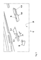
Fig. 2 zeigt einen ersten seitlichen Endbereich 34 einer Ausgestaltung eines Luftleitbauteils 10, bei dem ein Vorsprung 14.3 in dem ersten seitlichen Endbereich 34 quer zur Einschieberichtung E ausgerichtet ist und einen Anschlag für das quer zur Fahrzeuglängsrichtung -x erfolgende Einschieben bildet. Weitere Vorsprünge 14.5 und 14.6 entsprechen nach ihrer Form und Funktion den Vorsprüngen 14.1 und 14.2 aus derFig. 1 und unterscheiden sich von diesen im Wesentlichen nur durch ihre Anordnung und Abmessungen. Im Übrigen bezeichnen gleiche Bezugszeichen in den Figuren jeweils ihrer Funktion nach gleiche Elemente, auch wenn Abmessungen und Anordnung unterschiedlich sind. - Die
Fig. 3 zeigt eine Draufsicht auf eine Innenseite 28 des Karosserievorbaus 12 mit einem dem ersten Endbereich 34 gegenüberliegenden zweiten Endbereich 36 des Luftleitbauteils 10 im montierten Zustand. Der zweite Endbereich 36 weist eine Rastnase 38 auf, die eine Kante des Vorbaus 12 im montierten Zustand des Luftleitbauteils 10 hintergreift. Um ein Einschwenken der Rastnase 38 zu ermöglichen, besitzt der Teil 30 des Luftleitbauteils 10, der die vergleichsweise höhere Steifigkeit aufweist, eine Sollbiegestelle, die das zerstörungsfreie, im Wesentlichen in z-Richtung erfolgende Einschwenken der Rastnase in den Vorbau 12 erlaubt. - Weitere Vorsprünge 14.7 und 14.8 entsprechen nach ihrer Form und Funktion den Vorsprüngen 14.1 und 14.2 aus der
Fig. 1 und unterscheiden sich von diesen im Wesentlichen nur durch ihre Anordnung und Abmessungen. - Im Übrigen zeigt die
Fig. 3 , wie jeder Vorsprung 14.7, 14. 8 im montierten Zustand einen Rand der zugehörigen Ausnehmung 16.7, 16.8 auf der Innenseite 28 des Vorbaus 12 durch die Ausnehmung 16.7, 16.8 hindurch hintergreift.
Claims (12)
- Luftleitbauteil (10) eines Kraftfahrzeugs, mit hakenförmigen Vorsprüngen (14.1, 14,2), die durch ihre Form und Anordnung dazu eingerichtet sind, in Ausnehmungen (16.1, 16.2) eines Karosserievorbaus (12) des Kraftfahrzeugs eingeschoben zu werden, dadurch gekennzeichnet, dass das Luftleitbauteil (10) eine Montagefläche (18) aufweist, die dazu ausgestaltet ist, im montierten Zustand des Luftleitbauteils (10) an einer Außenseite (20) des Vorbaus (12) anzuliegen, wobei die Vorsprünge (14.1, 14.2) aus der Montagefläche (18) aufragen und Abmessungen aufweisen, die auf Abmessungen der Ausnehmungen (16.1, 16.2) des Vorbaus (12) so abgestimmt sind, dass jeder Vorsprung (14.1, 14.2) im montierten Zustand einen Rand (26) der Ausnehmung (16.1, 16,2) auf einer der Montagefläche (18) gegenüberliegenden Innenseite (28) des Vorbaus (12) durch die Ausnehmung (16.1, 16.2) hindurch hintergreift und wobei die Form und Anordnung der Vorsprünge (14.1, 14.2) ein quer zu einer Längsachse des Kraftfahrzeugs erfolgendes Einschieben der Vorsprünge (14.1, 14.2) in die Ausnehmungen (16.1, 16.2) erlaubt.
- Luftleitbauteil (10) nach Anspruch 1, dadurch gekennzeichnet, dass weitere Vorsprünge (14.5, 14, 6, 14,7, 14,8) über die Montagefläche (18) quer zur Fahrzeuglängsachse verteilt sind, von denen eine erste Teilmenge (14.5, 14,7) in Fahrtrichtung vorne am Luftleitbauteil (10) und eine zweite Teilmenge (14.6, 14.8) nach hinten versetzt auf der Montagefläche (18) angeordnet sind.
- Luftleitbauteil (10) nach Anspruch 2, dadurch gekennzeichnet, dass wenigstens ein Vorsprung aus der ersten Teilmenge (14.5, 14,7) in einem zur Fahrzeuglängsrichtung parallelen Abstand (d) zu einem Vorsprung aus der zweiten Teilmenge (14.6, 14.8) angeordnet ist.
- Luftleitbauteil (10) nach einem der vorhergehenden Ansprüche, dadurch gekennzeichnet, dass ein in einem ersten seitlichen Endbereich (34) des Luftleitbauteils (10) angeordneter Vorsprung (14.3) quer zu einer Einschieberichtung (E) ausgerichtet ist und einen Anschlag für das quer zur Fahrzeuglängsrichtung erfolgende Einschieben bildet.
- Luftleitbauteil (10) nach Anspruch 4, dadurch gekennzeichnet, dass in einem zweiten seitlichen Endbereich (36), der dem ersten seitlichen Endbereich (34) gegenüberliegt, eine Rastnase (38) vorgesehen ist, die eine Kante des Vorbaus (12) im montierten Zustand des Luftleitbauteils (10) hintergreift.
- Luftleitbauteil (10) nach einem der vorhergehenden Ansprüche, dadurch gekennzeichnet, dass es aus zwei miteinander fest verbundenen Teilen (30, 32) mit unterschiedlicher Steifigkeit besteht.
- Luftleitbauteil (10) nach Anspruch 4 und 6, dadurch gekennzeichnet, dass der Teil des Luftleitbauteils (10), der eine vergleichsweise höhere Steifigkeit aufweist, eine Sollbiegestelle besitzt, die ein zerstörungsfreies Einschwenken der Rastnase (38) in den Vorbau (12) ermöglicht.
- Zur Montage eines Luftleitbauteils (10) eingerichteter Karosserievorbau (12) eines Kraftfahrzeugs, der Ausnehmungen (16.1, 16.2) aufweist, die durch ihre Form und Anordnung dazu eingerichtet sind, Vorsprünge (14.1, 14,2) des Luftleitbauteils aufzunehmen, um das Luftleitbauteil (10) mit dem Vorbau zu verbinden (12), dadurch gekennzeichnet, dass die Form und Anordnung der Ausnehmungen (16.1, 16.2) ein quer zu einer Längsachse des Kraftfahrzeugs erfolgendes Einschieben der Vorsprünge (14.1, 14.2) in die Ausnehmungen erlaubt und wobei der Vorbau (12) eine Außenseite (20) aufweist, die dazu ausgestaltet ist, eine Anlagefläche für eine Montagefläche (18) des Luftleitbauteils (10) zu bilden, und wobei Abmessungen der Ausnehmungen (16.1, 16.2) so auf Abmessungen der Vorsprünge (14.1, 14.2) abgestimmt sind, dass jeder Vorsprung (14.1, 14.2) im montierten Zustand einen Rand (26) der Ausnehmung (16.1, 16.2) auf einer der Montagefläche (18) gegenüberliegenden Innenseite (28) des Vorbaus (12) durch die Ausnehmung (16.1, 16.2) hindurch hintergreift und wobei die Form und Anordnung der Ausnehmungen (16.1, 16.2) ein quer zu einer Längsachse des Kraftfahrzeugs erfolgendes Einschieben der Vorsprünge (14.1, 14.2) in die Ausnehmungen (16.1, 16.2) erlaubt.
- Vorbau (12) nach Anspruch 8, dadurch gekennzeichnet, dass die Ausnehmungen (16.1, 16.2) einen ersten Bereich (22) mit einer größeren lichten Weite (W1) und einen zweiten Bereich (24) mit einer kleineren lichten Weite (W2) aufweisen, wobei die größere lichte Weite (W1) so auf Abmessungen der Vorsprünge (14.1, 14.2) abgestimmt ist, dass die ersten Bereiche (22) die Vorsprünge (14.1, 14.2) beim Anlegen einer Montagefläche (18) des Luftleitbauteils (10) an eine Außenseite (20) des Vorbaus (12) aufnehmen und wobei die kleinere lichte Weite (W2) so auf Abmessungen der Vorsprünge (14.1, 14.2) abgestimmt ist, dass sie ein Einschieben der Vorsprünge 814.1, 14.2) aus dem ersten Bereich (22) in den zweiten Bereich (24) erlaubt, wobei die Vorsprünge (14.1, 14.2) einen Rand (26) des zweiten Bereichs (24) der Ausnehmung (16.1, 16.29 im eingeschobenen Zustand formschlüssig hintergreifen.
- Vorbau (12) nach Anspruch 9, dadurch gekennzeichnet, dass die ersten Bereiche (22) und die zweiten Bereiche (24) quer zur Fahrzeuglängsachse nebeneinander angeordnet sind.
- Vorbau (12) nach Anspruch 10, dadurch gekennzeichnet, dass der Übergang von der ersten lichten Weite (W1) auf die zweite lichte Weite (W2) in einer einzigen Stufe erfolgt.
- Vorbau (12) nach Anspruch 10 dass der Übergang von der ersten lichten Weite (W1) auf die zweite lichte Weite (W2) rampenförmig erfolgt.
Applications Claiming Priority (1)
| Application Number | Priority Date | Filing Date | Title |
|---|---|---|---|
| DE102008020082A DE102008020082A1 (de) | 2008-04-22 | 2008-04-22 | Luftleitbauteil und Karosserievorbau eines Kraftfahrzeuges |
Publications (2)
| Publication Number | Publication Date |
|---|---|
| EP2112055A1 true EP2112055A1 (de) | 2009-10-28 |
| EP2112055B1 EP2112055B1 (de) | 2012-04-18 |
Family
ID=40874778
Family Applications (1)
| Application Number | Title | Priority Date | Filing Date |
|---|---|---|---|
| EP09002806A Not-in-force EP2112055B1 (de) | 2008-04-22 | 2009-02-27 | Luftleitbauteil und Karosserievorbau eines Kraftfahrzeuges |
Country Status (4)
| Country | Link |
|---|---|
| US (1) | US7883140B2 (de) |
| EP (1) | EP2112055B1 (de) |
| AT (1) | ATE553986T1 (de) |
| DE (1) | DE102008020082A1 (de) |
Cited By (3)
| Publication number | Priority date | Publication date | Assignee | Title |
|---|---|---|---|---|
| GB2468535A (en) * | 2009-03-13 | 2010-09-15 | Nissan Motor Mfg | Apparatus for mounting a fascia to a vehicle |
| WO2012150094A1 (de) * | 2011-05-03 | 2012-11-08 | Lisa Dräxlmaier GmbH | Verbindung eines trägerteils mit einer einlage |
| FR2994929A1 (fr) * | 2012-09-04 | 2014-03-07 | Faurecia Bloc Avant | Assistance a l'assemblage par glissement de deux pieces de vehicule |
Families Citing this family (13)
| Publication number | Priority date | Publication date | Assignee | Title |
|---|---|---|---|---|
| JP4725365B2 (ja) * | 2006-03-01 | 2011-07-13 | 日産自動車株式会社 | 係合固定構造および係合固定方法 |
| DE102010021187B4 (de) | 2010-05-21 | 2021-12-30 | Apollo Vredestein B.V. | Frontspoiler eines Kraftfahrzeugs |
| JP5222921B2 (ja) * | 2010-10-06 | 2013-06-26 | 本田技研工業株式会社 | ディフューザ装置 |
| US8210600B1 (en) * | 2011-01-05 | 2012-07-03 | Ford Global Technologies, Llc | Aerodynamic package for an automotive vehicle |
| US8474214B2 (en) * | 2011-01-26 | 2013-07-02 | Nissan North America, Inc. | Connecting structure for automotive trim panels |
| DE102011056319A1 (de) * | 2011-12-13 | 2013-06-13 | Dr. Ing. H.C. F. Porsche Aktiengesellschaft | Luftleitvorrichtung |
| ES2526261B1 (es) * | 2013-07-05 | 2015-09-11 | Seat, S.A. | Sistema y procedimiento de montaje para un alerón en la carrocería de un vehículo |
| DE102014103823B4 (de) | 2014-03-20 | 2023-01-26 | Dr. Ing. H.C. F. Porsche Aktiengesellschaft | Zweiteiliger Spoiler oder Flügel |
| FR3038290B1 (fr) * | 2015-07-03 | 2017-07-28 | Peugeot Citroen Automobiles Sa | Ensemble comprenant une cloison et un deflecteur |
| JP2017173697A (ja) * | 2016-03-25 | 2017-09-28 | ヤマハ株式会社 | 取付け構造 |
| US10744858B2 (en) * | 2016-09-30 | 2020-08-18 | Nissan North America, Inc. | Vehicle body structure |
| US11472495B1 (en) | 2021-05-14 | 2022-10-18 | Ford Global Technologies, Llc | Quick-release vehicle air dam |
| DE102024109425A1 (de) | 2024-04-04 | 2025-10-09 | Dr. Ing. H.C. F. Porsche Aktiengesellschaft | Bugvorrichtung eines Kraftfahrzeugs und Verfahren zur Herstellung einer Bugvorrichtung |
Citations (3)
| Publication number | Priority date | Publication date | Assignee | Title |
|---|---|---|---|---|
| JPS61109903U (de) * | 1984-12-22 | 1986-07-11 | ||
| JPS6295967U (de) * | 1985-12-09 | 1987-06-18 | ||
| US20040135383A1 (en) | 2002-10-29 | 2004-07-15 | Tokai Kogyo Co., Ltd. | Bumper spoiler and bumper structure |
Family Cites Families (13)
| Publication number | Priority date | Publication date | Assignee | Title |
|---|---|---|---|---|
| US3813735A (en) * | 1971-04-05 | 1974-06-04 | W Thiermann | Snap-on attachment for utility service trailers and the like |
| DE2715986C2 (de) * | 1977-04-09 | 1983-06-30 | Wilhelm Karmann GmbH, 4500 Osnabrück | Stoßfänger für Kraftfahrzeuge |
| JPS61109903A (ja) | 1984-10-31 | 1986-05-28 | Kiyousan Denki Kk | 内燃機関用アクチエ−タ |
| JP2542810B2 (ja) | 1985-10-18 | 1996-10-09 | 三洋電機株式会社 | スイッチング制御型電源回路 |
| DE3812347A1 (de) * | 1988-04-14 | 1989-10-26 | Porsche Ag | Kraftfahrzeug mit einem verkleidungsteil |
| US5098765A (en) * | 1989-12-22 | 1992-03-24 | Chrysler Corportion | Fastening arrangement for plastic vehicle panel |
| FR2662981B1 (fr) * | 1990-06-08 | 1992-07-31 | Valeo Vision | Dispositif et procede pour le montage automatique d'un equipement sur support, et plus particulierement d'un dispositif d'eclairage et/ou de signalisation sur un vehicule automobile. |
| US5420762A (en) * | 1993-09-24 | 1995-05-30 | Trw Inc. | Automotive headlamp assembly fastening system |
| SE523327C2 (sv) * | 2001-03-07 | 2004-04-13 | Volvo Lastvagnar Ab | Frontkonstruktion hos ett tungt fordon samt en metod för att montera en modul i en sådan |
| US6929313B2 (en) * | 2002-03-23 | 2005-08-16 | Bayerische Motoren Werke Aktiengesellschaft | Plastic fender for a motor vehicle and device for fastening the same |
| DE10242787B3 (de) * | 2002-09-14 | 2004-04-15 | Dr.Ing.H.C. F. Porsche Ag | Lösbare Verbindung zwischen zwei angrenzenden Bauteilen, insbesondere Aussenhautteilen einer Fahrzeugkarosserie |
| DE10343381B4 (de) * | 2003-09-19 | 2005-12-08 | Dr.Ing.H.C. F. Porsche Ag | Lösbare Verbindung zwischen zwei angrenzenden Bauteilen, insbesondere Außenhautteilen einer Fahrzeugkarosserie |
| US7857610B2 (en) * | 2008-03-11 | 2010-12-28 | Safetynet Energy Management, Llc | Apparatus making thermoformed component with integral coined structure |
-
2008
- 2008-04-22 DE DE102008020082A patent/DE102008020082A1/de not_active Withdrawn
-
2009
- 2009-02-27 EP EP09002806A patent/EP2112055B1/de not_active Not-in-force
- 2009-02-27 AT AT09002806T patent/ATE553986T1/de active
- 2009-04-15 US US12/423,860 patent/US7883140B2/en active Active
Patent Citations (3)
| Publication number | Priority date | Publication date | Assignee | Title |
|---|---|---|---|---|
| JPS61109903U (de) * | 1984-12-22 | 1986-07-11 | ||
| JPS6295967U (de) * | 1985-12-09 | 1987-06-18 | ||
| US20040135383A1 (en) | 2002-10-29 | 2004-07-15 | Tokai Kogyo Co., Ltd. | Bumper spoiler and bumper structure |
Cited By (4)
| Publication number | Priority date | Publication date | Assignee | Title |
|---|---|---|---|---|
| GB2468535A (en) * | 2009-03-13 | 2010-09-15 | Nissan Motor Mfg | Apparatus for mounting a fascia to a vehicle |
| GB2468535B (en) * | 2009-03-13 | 2013-10-16 | Nissan Motor Mfg Uk Ltd | Mounting assembly of a fascia to a vehicle |
| WO2012150094A1 (de) * | 2011-05-03 | 2012-11-08 | Lisa Dräxlmaier GmbH | Verbindung eines trägerteils mit einer einlage |
| FR2994929A1 (fr) * | 2012-09-04 | 2014-03-07 | Faurecia Bloc Avant | Assistance a l'assemblage par glissement de deux pieces de vehicule |
Also Published As
| Publication number | Publication date |
|---|---|
| US7883140B2 (en) | 2011-02-08 |
| ATE553986T1 (de) | 2012-05-15 |
| US20090261619A1 (en) | 2009-10-22 |
| DE102008020082A1 (de) | 2009-10-29 |
| EP2112055B1 (de) | 2012-04-18 |
Similar Documents
| Publication | Publication Date | Title |
|---|---|---|
| EP2112055B1 (de) | Luftleitbauteil und Karosserievorbau eines Kraftfahrzeuges | |
| EP1790514B1 (de) | Türmodulträger | |
| DE102015106223A1 (de) | System zur Befestigung eines Türmoduls an einer Automobiltür | |
| DE102010050515A1 (de) | Fahrzeugverkleidungsteil und insbesondere ein Kühlergrill für ein Kraftfahrzeug sowie ein Verfahren zur Montage eines Fahrzeugverkleidungsteils | |
| DE102019116206A1 (de) | Heckklappe mit mechanisch gesicherter Heck- und Seitenspoilerverbindung | |
| DE102012022876B4 (de) | Hohlprofil mit einem Verstärkungselement | |
| DE102018211974B4 (de) | Stoßfängeranordnung und Füllelement | |
| DE102012022899A1 (de) | Verbindungselement zur Abstützung eines Stoßfängers eines Kraftfahrzeuges gegenüber einem Montageträger, Baueinheit mit einem solchen Verbindungselement sowie Verfahren zur Herstellung eines Verbindungselements | |
| EP2106984B1 (de) | Faltenbalg | |
| DE19911450B4 (de) | Konstruktion zur Installierung eines Armaturenbretts | |
| DE102009042415A1 (de) | Personenkraftwagen | |
| DE102008060715A1 (de) | Crashbox für eine Karosserie eines Kraftwagens | |
| EP2295297A1 (de) | Vorrichtung zur lagegenauen Montagepositionierung von mindestens zwei Bauteilen zueinander | |
| DE102015217463A1 (de) | Halter zur Befestigung an einem Strukturteil eines Kraftfahrzeuges sowie Anordnung eines Halters an einem Strukturteil eines Kraftfahrzeuges | |
| DE202008001814U1 (de) | Montagesystem für Stoßfänger | |
| WO2009053126A1 (de) | Schiebetürmodul für eine kraftfahrzeugtür | |
| EP2821329B1 (de) | System und Verfahren zum Montieren eines Spoilers an der Karosserie eines Fahrzeugs | |
| EP1619082B1 (de) | Kraftfahrzeug mit einer verriegelbaren Rastverbindung für einen Stossfänger | |
| DE102007016667A1 (de) | Befestigungsanordnung | |
| DE102008059294A1 (de) | Beleuchtungseinrichtung für ein Kraftfahrzeug | |
| DE102015209563B3 (de) | Design-Einsatzteil für die vordere Außenhaut eines Kraftfahrzeuges sowie Anordnung eines Design-Einsatzteils in einemVorderwagen eines Kraftfahrzeuges | |
| DE102013012532A1 (de) | Befestigungsanordnung | |
| DE102018131913B4 (de) | Heckspoiler | |
| DE102007051707B4 (de) | Befestigung einer Zierleiste | |
| DE102015211045A1 (de) | Frontendmodul für ein Kraftfahrzeug sowie Anordnung eines solchen Frontendmoduls an einem Montageträger eines Kraftfahrzeugs |
Legal Events
| Date | Code | Title | Description |
|---|---|---|---|
| PUAI | Public reference made under article 153(3) epc to a published international application that has entered the european phase |
Free format text: ORIGINAL CODE: 0009012 |
|
| AK | Designated contracting states |
Kind code of ref document: A1 Designated state(s): AT BE BG CH CY CZ DE DK EE ES FI FR GB GR HR HU IE IS IT LI LT LU LV MC MK MT NL NO PL PT RO SE SI SK TR |
|
| AX | Request for extension of the european patent |
Extension state: AL BA RS |
|
| RAP1 | Party data changed (applicant data changed or rights of an application transferred) |
Owner name: DR. ING. H.C. F. PORSCHE AG Owner name: PLASTAL GMBH |
|
| 17P | Request for examination filed |
Effective date: 20100428 |
|
| AKX | Designation fees paid |
Designated state(s): AT BE BG CH CY CZ DE DK EE ES FI FR GB GR HR HU IE IS IT LI LT LU LV MC MK MT NL NO PL PT RO SE SI SK TR |
|
| 17Q | First examination report despatched |
Effective date: 20100610 |
|
| RAP1 | Party data changed (applicant data changed or rights of an application transferred) |
Owner name: FAURECIA EXTERIORS GMBH Owner name: DR. ING. H.C. F. PORSCHE AG |
|
| GRAP | Despatch of communication of intention to grant a patent |
Free format text: ORIGINAL CODE: EPIDOSNIGR1 |
|
| GRAS | Grant fee paid |
Free format text: ORIGINAL CODE: EPIDOSNIGR3 |
|
| GRAA | (expected) grant |
Free format text: ORIGINAL CODE: 0009210 |
|
| AK | Designated contracting states |
Kind code of ref document: B1 Designated state(s): AT BE BG CH CY CZ DE DK EE ES FI FR GB GR HR HU IE IS IT LI LT LU LV MC MK MT NL NO PL PT RO SE SI SK TR |
|
| REG | Reference to a national code |
Ref country code: GB Ref legal event code: FG4D Free format text: NOT ENGLISH |
|
| REG | Reference to a national code |
Ref country code: CH Ref legal event code: EP |
|
| REG | Reference to a national code |
Ref country code: IE Ref legal event code: FG4D Free format text: LANGUAGE OF EP DOCUMENT: GERMAN |
|
| REG | Reference to a national code |
Ref country code: AT Ref legal event code: REF Ref document number: 553986 Country of ref document: AT Kind code of ref document: T Effective date: 20120515 |
|
| REG | Reference to a national code |
Ref country code: DE Ref legal event code: R096 Ref document number: 502009003240 Country of ref document: DE Effective date: 20120614 |
|
| REG | Reference to a national code |
Ref country code: NL Ref legal event code: VDEP Effective date: 20120418 |
|
| LTIE | Lt: invalidation of european patent or patent extension |
Effective date: 20120418 |
|
| PG25 | Lapsed in a contracting state [announced via postgrant information from national office to epo] |
Ref country code: NO Free format text: LAPSE BECAUSE OF FAILURE TO SUBMIT A TRANSLATION OF THE DESCRIPTION OR TO PAY THE FEE WITHIN THE PRESCRIBED TIME-LIMIT Effective date: 20120718 Ref country code: LT Free format text: LAPSE BECAUSE OF FAILURE TO SUBMIT A TRANSLATION OF THE DESCRIPTION OR TO PAY THE FEE WITHIN THE PRESCRIBED TIME-LIMIT Effective date: 20120418 Ref country code: SE Free format text: LAPSE BECAUSE OF FAILURE TO SUBMIT A TRANSLATION OF THE DESCRIPTION OR TO PAY THE FEE WITHIN THE PRESCRIBED TIME-LIMIT Effective date: 20120418 Ref country code: PL Free format text: LAPSE BECAUSE OF FAILURE TO SUBMIT A TRANSLATION OF THE DESCRIPTION OR TO PAY THE FEE WITHIN THE PRESCRIBED TIME-LIMIT Effective date: 20120418 Ref country code: FI Free format text: LAPSE BECAUSE OF FAILURE TO SUBMIT A TRANSLATION OF THE DESCRIPTION OR TO PAY THE FEE WITHIN THE PRESCRIBED TIME-LIMIT Effective date: 20120418 Ref country code: CY Free format text: LAPSE BECAUSE OF FAILURE TO SUBMIT A TRANSLATION OF THE DESCRIPTION OR TO PAY THE FEE WITHIN THE PRESCRIBED TIME-LIMIT Effective date: 20120418 Ref country code: IS Free format text: LAPSE BECAUSE OF FAILURE TO SUBMIT A TRANSLATION OF THE DESCRIPTION OR TO PAY THE FEE WITHIN THE PRESCRIBED TIME-LIMIT Effective date: 20120818 |
|
| PG25 | Lapsed in a contracting state [announced via postgrant information from national office to epo] |
Ref country code: SI Free format text: LAPSE BECAUSE OF FAILURE TO SUBMIT A TRANSLATION OF THE DESCRIPTION OR TO PAY THE FEE WITHIN THE PRESCRIBED TIME-LIMIT Effective date: 20120418 Ref country code: HR Free format text: LAPSE BECAUSE OF FAILURE TO SUBMIT A TRANSLATION OF THE DESCRIPTION OR TO PAY THE FEE WITHIN THE PRESCRIBED TIME-LIMIT Effective date: 20120418 Ref country code: PT Free format text: LAPSE BECAUSE OF FAILURE TO SUBMIT A TRANSLATION OF THE DESCRIPTION OR TO PAY THE FEE WITHIN THE PRESCRIBED TIME-LIMIT Effective date: 20120820 Ref country code: GR Free format text: LAPSE BECAUSE OF FAILURE TO SUBMIT A TRANSLATION OF THE DESCRIPTION OR TO PAY THE FEE WITHIN THE PRESCRIBED TIME-LIMIT Effective date: 20120719 Ref country code: LV Free format text: LAPSE BECAUSE OF FAILURE TO SUBMIT A TRANSLATION OF THE DESCRIPTION OR TO PAY THE FEE WITHIN THE PRESCRIBED TIME-LIMIT Effective date: 20120418 |
|
| PG25 | Lapsed in a contracting state [announced via postgrant information from national office to epo] |
Ref country code: NL Free format text: LAPSE BECAUSE OF FAILURE TO SUBMIT A TRANSLATION OF THE DESCRIPTION OR TO PAY THE FEE WITHIN THE PRESCRIBED TIME-LIMIT Effective date: 20120418 Ref country code: RO Free format text: LAPSE BECAUSE OF FAILURE TO SUBMIT A TRANSLATION OF THE DESCRIPTION OR TO PAY THE FEE WITHIN THE PRESCRIBED TIME-LIMIT Effective date: 20120418 Ref country code: CZ Free format text: LAPSE BECAUSE OF FAILURE TO SUBMIT A TRANSLATION OF THE DESCRIPTION OR TO PAY THE FEE WITHIN THE PRESCRIBED TIME-LIMIT Effective date: 20120418 Ref country code: DK Free format text: LAPSE BECAUSE OF FAILURE TO SUBMIT A TRANSLATION OF THE DESCRIPTION OR TO PAY THE FEE WITHIN THE PRESCRIBED TIME-LIMIT Effective date: 20120418 Ref country code: SK Free format text: LAPSE BECAUSE OF FAILURE TO SUBMIT A TRANSLATION OF THE DESCRIPTION OR TO PAY THE FEE WITHIN THE PRESCRIBED TIME-LIMIT Effective date: 20120418 Ref country code: EE Free format text: LAPSE BECAUSE OF FAILURE TO SUBMIT A TRANSLATION OF THE DESCRIPTION OR TO PAY THE FEE WITHIN THE PRESCRIBED TIME-LIMIT Effective date: 20120418 |
|
| PLBE | No opposition filed within time limit |
Free format text: ORIGINAL CODE: 0009261 |
|
| STAA | Information on the status of an ep patent application or granted ep patent |
Free format text: STATUS: NO OPPOSITION FILED WITHIN TIME LIMIT |
|
| PG25 | Lapsed in a contracting state [announced via postgrant information from national office to epo] |
Ref country code: IT Free format text: LAPSE BECAUSE OF FAILURE TO SUBMIT A TRANSLATION OF THE DESCRIPTION OR TO PAY THE FEE WITHIN THE PRESCRIBED TIME-LIMIT Effective date: 20120418 |
|
| 26N | No opposition filed |
Effective date: 20130121 |
|
| REG | Reference to a national code |
Ref country code: DE Ref legal event code: R097 Ref document number: 502009003240 Country of ref document: DE Effective date: 20130121 |
|
| PG25 | Lapsed in a contracting state [announced via postgrant information from national office to epo] |
Ref country code: BG Free format text: LAPSE BECAUSE OF FAILURE TO SUBMIT A TRANSLATION OF THE DESCRIPTION OR TO PAY THE FEE WITHIN THE PRESCRIBED TIME-LIMIT Effective date: 20120718 |
|
| BERE | Be: lapsed |
Owner name: DR. ING. H.C. F. PORSCHE A.G. Effective date: 20130228 Owner name: FAURECIA EXTERIORS G.M.B.H. Effective date: 20130228 |
|
| PG25 | Lapsed in a contracting state [announced via postgrant information from national office to epo] |
Ref country code: MC Free format text: LAPSE BECAUSE OF NON-PAYMENT OF DUE FEES Effective date: 20130228 |
|
| REG | Reference to a national code |
Ref country code: CH Ref legal event code: PL |
|
| PG25 | Lapsed in a contracting state [announced via postgrant information from national office to epo] |
Ref country code: CH Free format text: LAPSE BECAUSE OF NON-PAYMENT OF DUE FEES Effective date: 20130228 Ref country code: LI Free format text: LAPSE BECAUSE OF NON-PAYMENT OF DUE FEES Effective date: 20130228 Ref country code: ES Free format text: LAPSE BECAUSE OF FAILURE TO SUBMIT A TRANSLATION OF THE DESCRIPTION OR TO PAY THE FEE WITHIN THE PRESCRIBED TIME-LIMIT Effective date: 20120729 |
|
| REG | Reference to a national code |
Ref country code: IE Ref legal event code: MM4A |
|
| PG25 | Lapsed in a contracting state [announced via postgrant information from national office to epo] |
Ref country code: IE Free format text: LAPSE BECAUSE OF NON-PAYMENT OF DUE FEES Effective date: 20130227 Ref country code: BE Free format text: LAPSE BECAUSE OF NON-PAYMENT OF DUE FEES Effective date: 20130228 |
|
| PG25 | Lapsed in a contracting state [announced via postgrant information from national office to epo] |
Ref country code: MT Free format text: LAPSE BECAUSE OF FAILURE TO SUBMIT A TRANSLATION OF THE DESCRIPTION OR TO PAY THE FEE WITHIN THE PRESCRIBED TIME-LIMIT Effective date: 20120418 |
|
| PG25 | Lapsed in a contracting state [announced via postgrant information from national office to epo] |
Ref country code: TR Free format text: LAPSE BECAUSE OF FAILURE TO SUBMIT A TRANSLATION OF THE DESCRIPTION OR TO PAY THE FEE WITHIN THE PRESCRIBED TIME-LIMIT Effective date: 20120418 |
|
| PG25 | Lapsed in a contracting state [announced via postgrant information from national office to epo] |
Ref country code: MK Free format text: LAPSE BECAUSE OF FAILURE TO SUBMIT A TRANSLATION OF THE DESCRIPTION OR TO PAY THE FEE WITHIN THE PRESCRIBED TIME-LIMIT Effective date: 20120418 Ref country code: LU Free format text: LAPSE BECAUSE OF NON-PAYMENT OF DUE FEES Effective date: 20130227 Ref country code: HU Free format text: LAPSE BECAUSE OF FAILURE TO SUBMIT A TRANSLATION OF THE DESCRIPTION OR TO PAY THE FEE WITHIN THE PRESCRIBED TIME-LIMIT; INVALID AB INITIO Effective date: 20090227 |
|
| REG | Reference to a national code |
Ref country code: FR Ref legal event code: PLFP Year of fee payment: 8 |
|
| REG | Reference to a national code |
Ref country code: FR Ref legal event code: PLFP Year of fee payment: 9 |
|
| REG | Reference to a national code |
Ref country code: FR Ref legal event code: PLFP Year of fee payment: 10 |
|
| PGFP | Annual fee paid to national office [announced via postgrant information from national office to epo] |
Ref country code: GB Payment date: 20190218 Year of fee payment: 11 |
|
| PGFP | Annual fee paid to national office [announced via postgrant information from national office to epo] |
Ref country code: FR Payment date: 20190220 Year of fee payment: 11 Ref country code: AT Payment date: 20190219 Year of fee payment: 11 |
|
| REG | Reference to a national code |
Ref country code: AT Ref legal event code: MM01 Ref document number: 553986 Country of ref document: AT Kind code of ref document: T Effective date: 20200227 |
|
| GBPC | Gb: european patent ceased through non-payment of renewal fee |
Effective date: 20200227 |
|
| PG25 | Lapsed in a contracting state [announced via postgrant information from national office to epo] |
Ref country code: AT Free format text: LAPSE BECAUSE OF NON-PAYMENT OF DUE FEES Effective date: 20200227 |
|
| PG25 | Lapsed in a contracting state [announced via postgrant information from national office to epo] |
Ref country code: FR Free format text: LAPSE BECAUSE OF NON-PAYMENT OF DUE FEES Effective date: 20200229 Ref country code: GB Free format text: LAPSE BECAUSE OF NON-PAYMENT OF DUE FEES Effective date: 20200227 |
|
| P01 | Opt-out of the competence of the unified patent court (upc) registered |
Effective date: 20230526 |
|
| PGFP | Annual fee paid to national office [announced via postgrant information from national office to epo] |
Ref country code: DE Payment date: 20240219 Year of fee payment: 16 |
|
| REG | Reference to a national code |
Ref country code: DE Ref legal event code: R119 Ref document number: 502009003240 Country of ref document: DE |
|
| PG25 | Lapsed in a contracting state [announced via postgrant information from national office to epo] |
Ref country code: DE Free format text: LAPSE BECAUSE OF NON-PAYMENT OF DUE FEES Effective date: 20250902 |