EP2110317A1 - Dispositif pour transférer de matière en vrac stockée dans un réservoir - Google Patents
Dispositif pour transférer de matière en vrac stockée dans un réservoir Download PDFInfo
- Publication number
- EP2110317A1 EP2110317A1 EP08007282A EP08007282A EP2110317A1 EP 2110317 A1 EP2110317 A1 EP 2110317A1 EP 08007282 A EP08007282 A EP 08007282A EP 08007282 A EP08007282 A EP 08007282A EP 2110317 A1 EP2110317 A1 EP 2110317A1
- Authority
- EP
- European Patent Office
- Prior art keywords
- perforated plate
- base frame
- individual products
- clamping
- stiffening ribs
- Prior art date
- Legal status (The legal status is an assumption and is not a legal conclusion. Google has not performed a legal analysis and makes no representation as to the accuracy of the status listed.)
- Withdrawn
Links
Images


Classifications
-
- B—PERFORMING OPERATIONS; TRANSPORTING
- B65—CONVEYING; PACKING; STORING; HANDLING THIN OR FILAMENTARY MATERIAL
- B65B—MACHINES, APPARATUS OR DEVICES FOR, OR METHODS OF, PACKAGING ARTICLES OR MATERIALS; UNPACKING
- B65B35/00—Supplying, feeding, arranging or orientating articles to be packaged
- B65B35/06—Separating single articles from loose masses of articles
- B65B35/08—Separating single articles from loose masses of articles using pocketed conveyors
-
- B—PERFORMING OPERATIONS; TRANSPORTING
- B65—CONVEYING; PACKING; STORING; HANDLING THIN OR FILAMENTARY MATERIAL
- B65B—MACHINES, APPARATUS OR DEVICES FOR, OR METHODS OF, PACKAGING ARTICLES OR MATERIALS; UNPACKING
- B65B5/00—Packaging individual articles in containers or receptacles, e.g. bags, sacks, boxes, cartons, cans, jars
- B65B5/08—Packaging groups of articles, the articles being individually gripped or guided for transfer to the containers or receptacles
Definitions
- the invention relates to a device for transferring stored in a reservoir, formed from individual products bulk material to the individual products in the wells of a continuously or clocked moving film web transfer transfer device with the product outlet of the reservoir downstream downstream perforated plate, which is interchangeable arranged on a base frame.
- thermoforming machines are known in practice, which are used to fill in thermoforming machines as part of a filling station trained in earlier workstations of the thermoforming machine cups of the film web targeted at high speed with the individual products.
- This requires a separation of the individual products provided as bulk material, to which the individual products are added from the reservoir through the product outlet on the perforated plate whose holes are tuned to the size of the individual products that intact, undamaged individual products remain on the perforated plate, while dust and breakage to be excreted through the holes.
- the invention is therefore based on the object, a device of the type mentioned in such a way that with an improved cleaning ability of the plate holder, the interchangeability of the perforated plate is facilitated.
- the base frame is associated with at least one mounted in a slide support with a sloping to vertical backdrop mounted terminal block.
- the design is chosen so that the backdrop is formed by an open end cam, in which the terminal block can be used with a guide pin.
- the terminal block on the side facing away from the backdrop has a clamping strip against the base frame exciting clamping means.
- terminal strip is provided several times in an arrangement associated with the side edges of the perforated plate, since such a two-dimensional contact of the perforated plate on the base frame can be enforced to the exclusion of a possibility of tilting.
- the perforated plate is provided several times in a direction perpendicular to the conveying direction Reirang, as this embodiment provides a large effective Usable width can be achieved, which allows a simple increase in performance of the device by the modular structure.
- the base frame is inclined in the conveying direction; more effective and thus preferred is that the base frame is associated with at least one vibratory drive for conveying the products from the product outlet to the transfer device.
- a perforated plate with a plurality of holes adapted to the diameter and the shape of the individual products that stiffening ribs are formed on the side facing away from the individual products, the plate areas separate from each other, wherein only in the plate areas between the stiffening ribs, the holes are formed.
- bearing surfaces are provided without stiffening ribs to allow a good support on the base frame and coupling to the vibration drive.
- Thermoforming machines are used in particular in the pharmaceutical industry to package individual products such as tablets, dragees, pills or the like in blister packs, for which first a thermoforming machine is withdrawn from a supply roll as a film web and fed to a heating station in which the mold film is heated to deformation temperature and a forming station is fed, in which the wells of the blister packs are formed. In the so-trained wells then the individual products must be transferred, which are provided as bulk material.
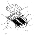
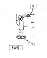
- the device according to the invention ( Fig. 1 ) as a coupling member between the reservoir 1 and the individual products in the wells of the film web transfer transfer device.
- the device according to the invention comprises in addition to the reservoir 1 with its product outlet 2 on a base frame in a plate holder 3 releasably and replaceably arranged perforated plate 4, which is downstream of the product outlet 2 downstream.
- the perforated plate 4 is multiple, namely twice present in a direction perpendicular to the conveying direction of the individual products Reihung, so that in a very simple way a effective large usable width results.
- Each perforated plate 4 has a plurality of holes adapted to the diameter and the shape of the individual products, which retain intact individual products on the surface of the perforated plate 4, but allow the separation of breakage and dust.
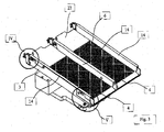
- stiffening ribs 5 On the side facing away from the individual products of the perforated plates 4 are stiffening ribs 5 ( Fig.
- the area directly under the product outlet 2 can not be used for fractional precipitation, since the resting on the perforated plate 4 individual products would be pressed from above through the overlying product column on the perforated plate 4 and the edges of the holes and the vibration movements of the perforated plate 4 could damage the individual products ,
- the area below the product outlet 2 must therefore remain free of holes and is thus lost for the fractional precipitation, thereby resulting in an extension of the perforated plate 4, in order to achieve a complete product separation. As conditions existed Therefore, the demands for the smallest possible space requirement with the highest possible performance.
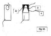
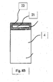
- the outlet opening 21 of the product outlet 2 has a rectangular shape oriented to a width of the perforated plate 4 approximate width and aligned to the size of the individual products length, the perforated plate 4 below the product outlet with a Having the length of the outlet opening 21 corresponding product inlet surface 22 free of holes.
- the entire width of the perforated plate 4 is utilized for the product separation in the application of the individual products to the perforated plate 4, so that a corresponding adaptation of the outlet opening 21 of the product outlet 2 results.
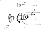
- the length of the hole-free area of the perforated plate 4, so the product inlet surface 22 is limited and minimizes the area that does not contribute to breakage, since initially the individual products extending from the edges of the product outlet 21 to the Distribute edges of the perforated plate 4 ( Fig. 8a ). It has proven to be advantageous if the outlet opening 21 is designed rectangular with a 60 to 95%, in particular 75 to 85% of the width of the perforated plate 4 corresponding width and 2 to 12 times, in particular 5 to 8 times The size of the products corresponding length, wherein the product inlet surface 22 has 3 to 8 times the size of the outlet opening 21.
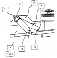
- a bulk material leveler 9 rotatable about a pivot axis 8 is arranged downstream of the perforated plate 4, which is detachably connected to the base frame 24 in order to change the perforated plates 4 located underneath the bulk material leveler 9 to enable.
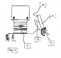
- the bulk leveler 9 itself has at its the perforated plate 4 facing the free end of an elastic lip 10 to ensure a gentle treatment of the individual products; the rotational position of the bulk material leveler 9 itself can be fixed by a fixing element 11, namely a clamping screw with a toggle wheel, in order to allow adaptation to the size of the individual products ( Fig. 10 ).
- a fixing element 11 namely a clamping screw with a toggle wheel
- On the clamping screw itself an adjusting lever 12 is arranged.
- the clamping screw is first loosened and twisted with the adjusting lever 12 of the bulk material leveler 9 so that it can be removed from an upwardly open screw holder 13 upwards.
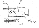
- each terminal block 14 is mounted in the slide carrier 15 with a sloping to the vertical backdrop 16, wherein the gate 16 through an open end Control cam 17 is formed, in which the terminal block 14 with a guide pin 18 is used.
- a clamping means On the opposite side of the gate 16 of the terminal strips 14 is a clamping means, namely a clamping screw 19 is arranged, which engages in a downwardly inclined to the vertical guided screw bearing 23, wherein the inclination direction of the link 16 of the inclination direction of the clamping screw 19 corresponds, so that at a twisting of the clamping screws 19 in the clamping direction, the terminal block 14 is pulled total according to the inclination down and the perforated plate 4th clamped against the plate holder 3.
- the clamping screw 19 is releasably attached to the terminal block 14 ( FIGS. 6a to 6c ).
- FIGS. 6a to 6c The FIGS.
- the terminal block 14 is provided several times in a side edges of the perforated plate 4 associated arrangement. Since in the embodiment shown two perforated plates 4 arranged side by side are present, the middle clamping bar 14 serves to load the two side edges of the left and right perforated plates 4. The presence of the middle clamping bar 14 also forces the formation of a receptacle 20 in the bulk material leveler 9. After removing the clamping screws 19 can be solved and the terminal strips 14 are moved in the gate 16 so that the guide pin 18 is removed from the open end cam 17 and thus the terminal block 14 can be removed from the disc holder 3.
- the perforated plates 4 are thus freely accessible and can be removed and replaced by other perforated plates 4, then only the previously cleaned Kiemmadorn 14 used again with their guide pins 18 in the cam 17 and must be pivoted to the perforated plates 4 for subsequent clamping by means of Clamping screw 19.
Priority Applications (2)
| Application Number | Priority Date | Filing Date | Title |
|---|---|---|---|
| EP08007282A EP2110317A1 (fr) | 2008-04-14 | 2008-04-14 | Dispositif pour transférer de matière en vrac stockée dans un réservoir |
| US12/422,734 US7905359B2 (en) | 2008-04-14 | 2009-04-13 | Device for delivering bulk material stored in a supply container |
Applications Claiming Priority (1)
| Application Number | Priority Date | Filing Date | Title |
|---|---|---|---|
| EP08007282A EP2110317A1 (fr) | 2008-04-14 | 2008-04-14 | Dispositif pour transférer de matière en vrac stockée dans un réservoir |
Publications (1)
| Publication Number | Publication Date |
|---|---|
| EP2110317A1 true EP2110317A1 (fr) | 2009-10-21 |
Family
ID=39743850
Family Applications (1)
| Application Number | Title | Priority Date | Filing Date |
|---|---|---|---|
| EP08007282A Withdrawn EP2110317A1 (fr) | 2008-04-14 | 2008-04-14 | Dispositif pour transférer de matière en vrac stockée dans un réservoir |
Country Status (2)
| Country | Link |
|---|---|
| US (1) | US7905359B2 (fr) |
| EP (1) | EP2110317A1 (fr) |
Cited By (1)
| Publication number | Priority date | Publication date | Assignee | Title |
|---|---|---|---|---|
| EP3919416A1 (fr) | 2020-06-03 | 2021-12-08 | Uhlmann Pac-Systeme GmbH & Co. KG | Dispositif de transfert de produits |
Families Citing this family (1)
| Publication number | Priority date | Publication date | Assignee | Title |
|---|---|---|---|---|
| CN117087933B (zh) * | 2023-10-18 | 2023-12-26 | 江苏百凌电器有限公司 | 一种电能表自动组箱装置 |
Citations (2)
| Publication number | Priority date | Publication date | Assignee | Title |
|---|---|---|---|---|
| DE102005049882B3 (de) * | 2005-10-17 | 2007-02-01 | Uhlmann Pac-Systeme Gmbh & Co. Kg. | Vorrichtung zum geordneten Zuführen und Ablegen zu verpackender Kleinteile in die Näpfe einer Folienbahn |
| EP1854722A2 (fr) * | 2006-05-11 | 2007-11-14 | UHLMANN PAC-SYSTEME GmbH & Co. KG | Dispositif pour alimenter et disposer de façon ordonnée des petits produits à emballer dans les alvéoles d'un film |
Family Cites Families (1)
| Publication number | Priority date | Publication date | Assignee | Title |
|---|---|---|---|---|
| GB0301509D0 (en) * | 2002-10-17 | 2003-02-19 | Varco Int | Vibratory seperator and screen assembly |
-
2008
- 2008-04-14 EP EP08007282A patent/EP2110317A1/fr not_active Withdrawn
-
2009
- 2009-04-13 US US12/422,734 patent/US7905359B2/en not_active Expired - Fee Related
Patent Citations (2)
| Publication number | Priority date | Publication date | Assignee | Title |
|---|---|---|---|---|
| DE102005049882B3 (de) * | 2005-10-17 | 2007-02-01 | Uhlmann Pac-Systeme Gmbh & Co. Kg. | Vorrichtung zum geordneten Zuführen und Ablegen zu verpackender Kleinteile in die Näpfe einer Folienbahn |
| EP1854722A2 (fr) * | 2006-05-11 | 2007-11-14 | UHLMANN PAC-SYSTEME GmbH & Co. KG | Dispositif pour alimenter et disposer de façon ordonnée des petits produits à emballer dans les alvéoles d'un film |
Cited By (1)
| Publication number | Priority date | Publication date | Assignee | Title |
|---|---|---|---|---|
| EP3919416A1 (fr) | 2020-06-03 | 2021-12-08 | Uhlmann Pac-Systeme GmbH & Co. KG | Dispositif de transfert de produits |
Also Published As
| Publication number | Publication date |
|---|---|
| US20090255858A1 (en) | 2009-10-15 |
| US7905359B2 (en) | 2011-03-15 |
Similar Documents
| Publication | Publication Date | Title |
|---|---|---|
| DE3322340C2 (fr) | ||
| DE2541914B2 (de) | Vorrichtung zum Einbringen von Zwischenlagen zwischen Fleischbällchen o.dgl | |
| DE2226995A1 (de) | Vorrichtung zum automatischen Ein füllen von scheibenförmigen Gegenstanden, z B Biskuits, in einseitig offene Ver packungsbehalter | |
| DE2929851C2 (fr) | ||
| EP2816305A1 (fr) | Dispositif de chargement et de déchargement d'une plaque de réglage d'une installation de lyophilisation et son procédé | |
| DE602004012576T2 (de) | Vorrichtung und Verfahren zum automatischen Anpassen eines Förderers, insbesondere für eine automatische Verpackungsmaschine, an die Verpackungsgrösse | |
| EP2110318B1 (fr) | Dispositif pour transférer de matière en vrac stockée dans un réservoir | |
| EP0362740B1 (fr) | Procédé et dispositif pour fabriquer et convoyer des piles de coupons en feuille | |
| EP1775219A2 (fr) | Dispositif pour alimenter et disposer de façon ordonnée des petites produits à emballer dans les alvéoles d'un film | |
| DE1959174C3 (de) | Vorrichtung zum Aufstapeln von Kartonzuschnitten | |
| DE60001034T2 (de) | Vorrichtung zum Zuführen von Tabletten in einer Verpackungsmaschine | |
| EP2110317A1 (fr) | Dispositif pour transférer de matière en vrac stockée dans un réservoir | |
| DE3713036A1 (de) | Vorsatzklebeeinrichtung fuer klebebindemaschine | |
| DE2418562C2 (de) | Vorrichtung zum Entleeren von Schragen | |
| EP2110316B1 (fr) | Dispositif pour transférer du matériau en vrac stocké dans un réservoir | |
| DE60004351T2 (de) | Förderer für blisterverpackungen oder stapel von blisterverpackungen, mit aufnahmefächern mit variabler höhe | |
| DE552823C (de) | Kartentransportvorrichtung fuer statistische Maschinen | |
| DE60028163T2 (de) | Vorrichtung zum Zuführen von Zigarren | |
| DE1904558A1 (de) | Einrichtung zum Abteilen und Auswerfen von Paketen plattenfoermiger Erzeugnisse | |
| DE102004025840A1 (de) | Vorrichtung zur Übergabe von festen Produkten in die Näpfe einer bewegten Warenbahn | |
| DE2516946C3 (de) | Antriebsvorrichtung für einen Bogeneinleger | |
| DE1936778A1 (de) | Vorrichtung zur Stapelentnahme des jeweils untersten Kartonzuschnitts | |
| DE10134602B4 (de) | Bandförderer für Stückgut | |
| DE4232963C1 (de) | Vorrichtung zum Aufbringen eines bedruckten Labels auf den Seitenwänden eines Kunststoffbehälters | |
| DE202019106430U1 (de) | Selbstzentrierende Fördereinrichtung |
Legal Events
| Date | Code | Title | Description |
|---|---|---|---|
| PUAI | Public reference made under article 153(3) epc to a published international application that has entered the european phase |
Free format text: ORIGINAL CODE: 0009012 |
|
| 17P | Request for examination filed |
Effective date: 20081023 |
|
| AK | Designated contracting states |
Kind code of ref document: A1 Designated state(s): AT BE BG CH CY CZ DE DK EE ES FI FR GB GR HR HU IE IS IT LI LT LU LV MC MT NL NO PL PT RO SE SI SK TR |
|
| AX | Request for extension of the european patent |
Extension state: AL BA MK RS |
|
| AKX | Designation fees paid |
Designated state(s): DE FR GB IE IT SE |
|
| GRAP | Despatch of communication of intention to grant a patent |
Free format text: ORIGINAL CODE: EPIDOSNIGR1 |
|
| STAA | Information on the status of an ep patent application or granted ep patent |
Free format text: STATUS: THE APPLICATION IS DEEMED TO BE WITHDRAWN |
|
| 18D | Application deemed to be withdrawn |
Effective date: 20110830 |