EP2109168A2 - Alkali-Trockenbatterie und Herstellungsverfahren dafür - Google Patents
Alkali-Trockenbatterie und Herstellungsverfahren dafür Download PDFInfo
- Publication number
- EP2109168A2 EP2109168A2 EP09150151A EP09150151A EP2109168A2 EP 2109168 A2 EP2109168 A2 EP 2109168A2 EP 09150151 A EP09150151 A EP 09150151A EP 09150151 A EP09150151 A EP 09150151A EP 2109168 A2 EP2109168 A2 EP 2109168A2
- Authority
- EP
- European Patent Office
- Prior art keywords
- positive electrode
- manganese dioxide
- hollow
- pellets
- battery case
- Prior art date
- Legal status (The legal status is an assumption and is not a legal conclusion. Google has not performed a legal analysis and makes no representation as to the accuracy of the status listed.)
- Granted
Links
Images

Classifications
-
- H—ELECTRICITY
- H01—ELECTRIC ELEMENTS
- H01M—PROCESSES OR MEANS, e.g. BATTERIES, FOR THE DIRECT CONVERSION OF CHEMICAL ENERGY INTO ELECTRICAL ENERGY
- H01M4/00—Electrodes
- H01M4/02—Electrodes composed of, or comprising, active material
- H01M4/06—Electrodes for primary cells
- H01M4/08—Processes of manufacture
-
- H—ELECTRICITY
- H01—ELECTRIC ELEMENTS
- H01M—PROCESSES OR MEANS, e.g. BATTERIES, FOR THE DIRECT CONVERSION OF CHEMICAL ENERGY INTO ELECTRICAL ENERGY
- H01M4/00—Electrodes
- H01M4/02—Electrodes composed of, or comprising, active material
- H01M4/36—Selection of substances as active materials, active masses, active liquids
- H01M4/48—Selection of substances as active materials, active masses, active liquids of inorganic oxides or hydroxides
- H01M4/50—Selection of substances as active materials, active masses, active liquids of inorganic oxides or hydroxides of manganese
-
- H—ELECTRICITY
- H01—ELECTRIC ELEMENTS
- H01M—PROCESSES OR MEANS, e.g. BATTERIES, FOR THE DIRECT CONVERSION OF CHEMICAL ENERGY INTO ELECTRICAL ENERGY
- H01M6/00—Primary cells; Manufacture thereof
- H01M6/04—Cells with aqueous electrolyte
- H01M6/06—Dry cells, i.e. cells wherein the electrolyte is rendered non-fluid
- H01M6/08—Dry cells, i.e. cells wherein the electrolyte is rendered non-fluid with cup-shaped electrodes
-
- H—ELECTRICITY
- H01—ELECTRIC ELEMENTS
- H01M—PROCESSES OR MEANS, e.g. BATTERIES, FOR THE DIRECT CONVERSION OF CHEMICAL ENERGY INTO ELECTRICAL ENERGY
- H01M6/00—Primary cells; Manufacture thereof
- H01M6/04—Cells with aqueous electrolyte
- H01M6/06—Dry cells, i.e. cells wherein the electrolyte is rendered non-fluid
- H01M6/08—Dry cells, i.e. cells wherein the electrolyte is rendered non-fluid with cup-shaped electrodes
- H01M6/085—Dry cells, i.e. cells wherein the electrolyte is rendered non-fluid with cup-shaped electrodes of the reversed type, i.e. anode in the centre
-
- H—ELECTRICITY
- H01—ELECTRIC ELEMENTS
- H01M—PROCESSES OR MEANS, e.g. BATTERIES, FOR THE DIRECT CONVERSION OF CHEMICAL ENERGY INTO ELECTRICAL ENERGY
- H01M4/00—Electrodes
- H01M4/02—Electrodes composed of, or comprising, active material
- H01M4/04—Processes of manufacture in general
- H01M4/043—Processes of manufacture in general involving compressing or compaction
- H01M4/0433—Molding
-
- H—ELECTRICITY
- H01—ELECTRIC ELEMENTS
- H01M—PROCESSES OR MEANS, e.g. BATTERIES, FOR THE DIRECT CONVERSION OF CHEMICAL ENERGY INTO ELECTRICAL ENERGY
- H01M4/00—Electrodes
- H01M4/02—Electrodes composed of, or comprising, active material
- H01M4/62—Selection of inactive substances as ingredients for active masses, e.g. binders, fillers
- H01M4/624—Electric conductive fillers
- H01M4/625—Carbon or graphite
-
- H—ELECTRICITY
- H01—ELECTRIC ELEMENTS
- H01M—PROCESSES OR MEANS, e.g. BATTERIES, FOR THE DIRECT CONVERSION OF CHEMICAL ENERGY INTO ELECTRICAL ENERGY
- H01M50/00—Constructional details or processes of manufacture of the non-active parts of electrochemical cells other than fuel cells, e.g. hybrid cells
- H01M50/10—Primary casings; Jackets or wrappings
- H01M50/102—Primary casings; Jackets or wrappings characterised by their shape or physical structure
- H01M50/107—Primary casings; Jackets or wrappings characterised by their shape or physical structure having curved cross-section, e.g. round or elliptic
-
- Y—GENERAL TAGGING OF NEW TECHNOLOGICAL DEVELOPMENTS; GENERAL TAGGING OF CROSS-SECTIONAL TECHNOLOGIES SPANNING OVER SEVERAL SECTIONS OF THE IPC; TECHNICAL SUBJECTS COVERED BY FORMER USPC CROSS-REFERENCE ART COLLECTIONS [XRACs] AND DIGESTS
- Y02—TECHNOLOGIES OR APPLICATIONS FOR MITIGATION OR ADAPTATION AGAINST CLIMATE CHANGE
- Y02E—REDUCTION OF GREENHOUSE GAS [GHG] EMISSIONS, RELATED TO ENERGY GENERATION, TRANSMISSION OR DISTRIBUTION
- Y02E60/00—Enabling technologies; Technologies with a potential or indirect contribution to GHG emissions mitigation
- Y02E60/10—Energy storage using batteries
-
- Y—GENERAL TAGGING OF NEW TECHNOLOGICAL DEVELOPMENTS; GENERAL TAGGING OF CROSS-SECTIONAL TECHNOLOGIES SPANNING OVER SEVERAL SECTIONS OF THE IPC; TECHNICAL SUBJECTS COVERED BY FORMER USPC CROSS-REFERENCE ART COLLECTIONS [XRACs] AND DIGESTS
- Y10—TECHNICAL SUBJECTS COVERED BY FORMER USPC
- Y10T—TECHNICAL SUBJECTS COVERED BY FORMER US CLASSIFICATION
- Y10T29/00—Metal working
- Y10T29/49—Method of mechanical manufacture
- Y10T29/49002—Electrical device making
- Y10T29/49108—Electric battery cell making
- Y10T29/4911—Electric battery cell making including sealing
Definitions
- the invention relates to an alkaline dry battery and a method for producing the same, and, particularly to a positive electrode used in an alkaline dry battery.
- Alkaline dry batteries generally have an inside-out structure. That is, a cylindrical positive electrode with a hollow is disposed in a battery case serving as the positive electrode terminal so as to closely adhere to the inner face of the battery case, and a negative electrode is disposed in the hollow with a separator interposed therebetween.
- Manganese dioxide powder is used as the positive electrode active material. Natural manganese dioxide (NMD), chemical manganese dioxide (CMD), or industrially produced manganese dioxide such as electrolytic manganese dioxide (EMD) is used as manganese dioxide. Among them, electrolytic manganese dioxide is used advantageously. Electrolytic manganese dioxide usually contains moisture, ash, and other unavoidable components, with the manganese dioxide (MnO 2 ) purity being a little more than 90%.
- Japanese Laid-Open Patent Publication No. Hei 10-144304 proposes an alkaline dry battery using a positive electrode with a core formation density of 2.9 to 3.1 g/cc.
- This positive electrode is produced by adding a water-soluble binder such as polyacrylic acid to a mixture of manganese dioxide (positive electrode active material) and graphite (conductive material), and the amount of the water-soluble binder is 0.6 to 1.5% by weight of the manganese dioxide.
- Japanese Laid-Open Patent Publication No. Hei 09-180708 proposes an alkaline dry battery using a positive electrode pellet containing manganese dioxide and a conductive material.
- the positive electrode pellet has pores with pore sizes of 3 nm to 400 ⁇ m, and the amount of the pores is 0.14 cc/g or more and 0.24 cc/g or less per unit weight.
- Japanese Laid-Open Patent Publication No. Hei 10-144304 a large amount of a binder is used to produce the positive electrode, in order to prevent a decline in the positive electrode strength due to decreased active material and increased pores in the positive electrode.
- the large binder amount makes the positive electrode mixture adhesive, the positive electrode mixture tends to adhere to the die or tooling when it is compression molded into a positive electrode pellet or positive electrode. It is thus difficult to produce a predetermined positive electrode pellet or positive electrode. Also, the mold release pressure becomes high and the life of the molding machine tends to become short. Also, in Japanese Laid-Open Patent Publication No.
- an object of the invention is to provide an alkaline dry battery having a low manganese dioxide density in the positive electrode but having excellent discharge performance, and a method for producing such an alkaline dry battery.
- the invention relates to an alkaline dry battery including: a cylindrical battery case with a bottom; a cylindrical positive electrode having a hollow, being in contact with an inner face of the battery case, and containing a manganese dioxide powder and a graphite powder; a negative electrode disposed in the hollow of the positive electrode; a separator interposed between the positive electrode and the negative electrode; and an alkaline electrolyte.
- the positive electrode has cracks therein, and the cracks are substantially arc-shaped in a cross-section perpendicular to the axial direction of the positive electrode and extend in the axial direction of the positive electrode.
- the positive electrode has a manganese dioxide density of 2.15 to 2.30 g/cm 3 .
- the manganese dioxide powder preferably has a mean particle size (D50) of 45 to 75 ⁇ m.
- the graphite powder preferably has a mean particle size (D50) of 20 to 50 ⁇ m.
- the water content in the positive electrode is preferably 10 to 12 parts by weight per 100 parts by weight of the manganese dioxide powder.
- the invention also relates to a method for producing an alkaline dry battery, including the steps of:
- the content of the graphite powder in the positive electrode mixture is preferably 10 to 15 parts by weight per 100 parts by weight of the total of the manganese dioxide powder and the graphite powder.
- the alkaline dry battery of the invention has a high positive electrode reaction efficiency and can provide good discharge performance with less active material than conventional amounts. Therefore, the alkaline dry battery can be produced at low costs. Also, according to the production method of the invention, such an alkaline dry battery can be produced easily and reliably.
- the invention relates to an alkaline dry battery including: a cylindrical battery case with a bottom; a cylindrical positive electrode having a hollow, being in contact with an inner face of the battery case, and containing a manganese dioxide powder and a graphite powder; a negative electrode disposed in the hollow of the positive electrode; a separator interposed between the positive electrode and the negative electrode; and an alkaline electrolyte.
- the invention is characterized in that the positive electrode has cracks therein that are substantially arc-shaped in a cross-section perpendicular to the axial direction of the positive electrode and extend in the axial direction of the positive electrode, and that the positive electrode has a manganese dioxide density of 2.15 to 2.30 g/cm 3 .
- the reaction efficiency is high on the inner side facing the hollow, i.e., near the separator, and the reaction efficiency lowers toward the outer side of the positive electrode.
- cracks are formed in the areas where the reaction efficiency is low.
- the cracks are substantially arc-shaped in a cross-section perpendicular to the axial direction of the positive electrode, and extend in the axial direction of the positive electrode. In a cross-section perpendicular to the axial direction of the positive electrode, these cracks do not extend around in the positive electrode so that they do not surround the negative electrode.
- these cracks extend discontinuously in the circumferential direction of the positive electrode in a cross-section perpendicular to the axial direction of the positive electrode.
- the positive electrode has sufficient conductivity.
- the positive electrode has a low manganese dioxide density, excellent discharge performance can be obtained. Therefore, the amount of the active material can be reduced and cost reduction is possible.
- the amount of electrolyte contained in the positive electrode increases, which permits an improvement in the reaction efficiency of the positive electrode, i.e., the utilization rate of the positive electrode active material.
- the manganese dioxide density in the positive electrode is 2.15 to 2.30 g/cm 3 , which is lower than the manganese dioxide density (approximately 2.5 g/cm 3 ) in conventional positive electrodes. Hence, cost reduction is possible by decreasing the amount of manganese dioxide. In this way, the invention can provide an inexpensive alkaline dry battery with excellent discharge performance.
- the crack refers to a linear void space whose width is substantially greater than the particle size of the manganese dioxide powder and is less than approximately 0.5 mm in a cross-section perpendicular to the axial direction of the positive electrode.
- the manganese dioxide density in the positive electrode is calculated from the positive electrode volume after battery production and the manganese dioxide amount. It should be noted that the amount of impurities contained in the manganese dioxide (electrolytic manganese dioxide) is not reckoned into the amount of the manganese dioxide.
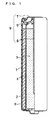
- FIG. 1 is a partially sectional front view of an alkaline dry battery of the invention.
- a hollow cylindrical positive electrode 2 is inserted into a cylindrical battery case 1 having a bottom and made of a nickel plated steel plate.
- the positive electrode 2 comprises, for example, a mixture of manganese dioxide serving as a positive electrode active material, a graphite powder as a conductive material, and an alkaline electrolyte.
- the battery case 1 has a flat inner face on which a graphite coating film (not shown) is formed.
- the hollow of the positive electrode 2 is filled with a gelled negative electrode 3 with a separator 4 interposed therebetween.
- the negative electrode 3 comprises, for example, a mixture of a gelling agent such as sodium polyacrylate, an alkaline electrolyte, and a negative electrode active material.
- the negative electrode active material can be, for example, a zinc powder or zinc alloy powder.
- the zinc alloy contains, for example Bi, In, or Al.
- the separator can be made of, for example, non-woven fabric composed mainly of polyvinyl alcohol fibers and rayon fibers.
- the electrolyte can be, for example, an aqueous solution of potassium hydroxide or sodium hydroxide.
- the opening of the battery case 1 is sealed with a seal assembly 9.
- the seal assembly 9 is composed of a synthetic resin gasket 5, a bottom plate 7 serving as the negative electrode terminal, and a negative electrode current collector 6.
- the negative electrode current collector 6 is inserted into the gelled negative electrode 3.
- the body of the negative electrode current collector 6 is inserted through the central through-hole of the gasket 5, and the head of the negative electrode current collector 6 is welded to the bottom plate 7.
- the open edge of the battery case 1 is crimped onto the circumference of the bottom plate 7 with the outer edge of the gasket 5 interposed therebetween.
- the outer surface of the battery case 1 is covered with a label 8.
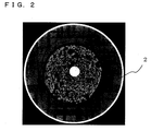
- FIG. 2 shows a photo of a cross-section of a cylindrical alkaline dry battery (a cross-section perpendicular to the axial direction of the cylindrical alkaline dry battery) as an example of the state of a transverse section of the cylindrical alkaline dry battery of FIG. 1 .
- the positive electrode 2 has cracks therein, and the cracks are substantially arc-shaped in a cross-section perpendicular to the axial direction of the positive electrode 2 and extend in the axial direction of the positive electrode. In a cross-section perpendicular to the axial direction of the positive electrode 2, these cracks do not extend around in the positive electrode so that they do not surround the negative electrode 3.
- these cracks extend discontinuously in the circumferential direction of the positive electrode 2 in a cross-section perpendicular to the axial direction of the positive electrode.
- the positive electrode 2 therefore has sufficient conductivity.
- the length of a crack (length of a substantial arc) can be, for example, 1/4 to 1/2 of the circumference of the part of the positive electrode having the crack.
- the length of the crack in the axial direction of the positive electrode 2 can be, for example, 50 to 90% of the height of the positive electrode.
- the manganese dioxide density in the positive electrode having the cracks is 2.15 to 2.30 g/cm 3 .
- the positive electrode has a low manganese dioxide density, and the positive electrode has the cracks therein, i.e., areas of low reaction efficiency are replaced with void spaces. Therefore, without causing a significant degradation in discharge performance, the amount of the active material can be reduced and cost reduction is possible. Since the formation of the cracks is facilitated by swelling of the positive electrode with water, it is preferable that the water content in the positive electrode be 10 to 12 parts by weight per 100 parts by weight of the manganese dioxide.
- the positive electrode does not swell sufficiently, so the cracks are unlikely to be formed. If the water content in the positive electrode exceeds 12 parts by weight per 100 parts by weight of the manganese dioxide, the water content (electrolyte amount) becomes excessive, thereby increasing the possibility of leakage.
- the method for producing an alkaline dry battery of the invention includes the steps of:
- step (3) the positive electrode pellets are stacked coaxially and inserted into a battery case so that their hollows communicate with one another. Subsequently, a pin is inserted into the hollows of the positive electrode pellets. It should be noted that there is a gap of 0.2 to 0.5 mm between the pin and the positive electrode pellets. Thus, when a pressure is applied to the positive electrode pellets to produce a positive electrode, the positive electrode pellets deform toward the pin so as to close the gap, so that low-density areas are formed therein.
- the positive electrode prepared in step (3) has a manganese dioxide density of 2.25 to 2.39 g/cm 3 . When an electrolyte is injected in step (4), the positive electrode swells, so that cracks are formed in the low-density areas.
- a manganese dioxide powder serving as a positive electrode active material, a graphite powder as a conductive material, and an alkaline electrolyte are mixed in a predetermined weight ratio. This mixture is evenly stirred and mixed with a mixer or the like, and then shaped into granules of certain granule size, to obtain a granular positive electrode mixture.
- the mean particle size (D50) (median diameter) of the granular positive electrode mixture is, for example 0.4 to 0.7 mm.
- the alkaline electrolyte can be, for example, an aqueous solution of potassium hydroxide.
- the graphite powder content in the positive electrode mixture be 10 to 15 parts by weight per 100 parts by weight of the total of the manganese dioxide powder and the graphite powder.
- step (2) which will be described later, positive electrode pellets having a relatively high manganese dioxide density of 2.40 to 2.50 are produced, and the positive electrode pellets have sufficient strength.
- the amount of the binder necessary is smaller than conventional amounts, which is advantageous in terms of costs. With respect to the amount of the binder added to the positive electrode mixture, a less amount is more preferable, and adding no binder to the positive electrode mixture is particularly preferable.
- the mean particle size (D50) (median diameter) of the manganese dioxide powder is preferably 45 to 75 ⁇ m. When such manganese dioxide is used, the manganese dioxide particles in the positive electrode are not packed too densely, and the electrolyte (water) easily permeates the positive electrode, thereby facilitating the formation of the cracks.
- the mean particle sizes in this range are relatively larger than conventional ones, and the trouble of pulverization can thus be reduced, which is also advantageous in terms of costs. If the mean particle size (D50) of the manganese dioxide powder is less than 45 ⁇ m, it is difficult for the electrolyte (water) to permeate the positive electrode. If the mean particle size (D50) of the manganese dioxide powder is greater than 75 ⁇ m, the cracks become too large, and the positive electrode may collapse.
- the mean particle size (D50) (median diameter) of the graphite powder is preferably 20 to 50 ⁇ m. When such graphite is used, the graphite particles in the positive electrode are not packed too densely, and the electrolyte (water) easily permeates the positive electrode, thereby facilitating the formation of the cracks.
- the mean particle sizes in this range are relatively larger than conventional ones, and the trouble of pulverization can thus be reduced, which is also advantageous in terms of costs. If the mean particle size (D50) of the graphite powder is less than 20 ⁇ m, it is difficult for the electrolyte (water) to permeate the positive electrode. If the mean particle size (D50) of the graphite powder is greater than 50 ⁇ m, the cracks become too large, and the positive electrode may collapse.
- FIG. 3 is a schematic longitudinal sectional view showing an example of step (2) in the production method of an alkaline dry battery of the invention.
- the granular positive electrode mixture prepared in step (1) is compression molded in the following manner, to obtain a positive electrode pellet 15.
- a die 11, a center pin 13, a lower molding punch 14a, and an upper molding punch 14b are prepared.
- the center pin 13 is disposed in the center of the hollow of the die 11 with gaps therebetween.
- the lower molding punch 14a is then inserted into the gaps, into which a granular electrode mixture 12 is to be charged.
- the center pin 13 is passed through the hole of the lower molding punch 14a.
- the granular electrode mixture 12 is charged into the gaps between the die 11 and the center pin 13.
- the lower molding punch 14a is moved down to a position slightly lower than the predetermined position and then moved up to the predetermined position.
- the granular electrode mixture 12 is smoothed over with a spatula or the like so as to be flush with the top face of the die 11.
- the center pin 13 is pushed up so that it fits into the recess at the lower end of the upper molding punch 14b, and then the upper molding punch 14b is pushed down to compression mold the charged granular electrode mixture 12. In this way, the hollow cylindrical positive electrode pellet 15 is produced.
- the manganese dioxide density in the positive electrode pellet is 2.4 to 2.5 g/cm 3 , which is relatively high.
- the positive electrode pellet thus has sufficient strength. Therefore, the positive electrode pellet does not collapse when the positive electrode pellet is transported to step (3) which will be described later or when it is inserted into the battery case in step (3).
- the pressure applied to mold the positive electrode pellet 15 pressure applied by the upper molding punch 14b
- the manganese dioxide density in the positive electrode pellet 15 can be controlled.
- FIG. 4 is a schematic longitudinal sectional view showing an example of step (3) in the production method of an alkaline dry battery of the invention.
- a lower molding punch 24a is inserted into the hollow of a hollow cylindrical cartridge 21.
- the cylindrical battery case 1 having a bottom and serving as the positive electrode terminal is disposed on the lower molding punch 24a in the hollow of the cartridge 21.
- Two positive electrode pellets 15 are inserted into the battery case 1. At this time, the two positive electrode pellets 15 are stacked coaxially, so that the hollows of the two positive electrode pellets communicate with each other.
- a cylindrical pin 23 having a diameter smaller than the internal diameter of the positive electrode pellets 15 by 0.2 to 0.5 mm is disposed in the hollows of the positive electrode pellets 15.
- the positive electrode pellets 15 With the pin 23 inserted in the hollow of a hollow cylindrical upper molding punch 24b, the positive electrode pellets 15 are pressed by the upper molding punch 24b from above at a pressure of 40 to 130 MPa per unit cross-sectional area of the positive electrode pellets 15 to compression mold the positive electrode pellets 15.
- the cross-sectional area as used herein refers to the area of a cross-section perpendicular to the axial direction of the positive electrode pellets 15. In this way, the hollow cylindrical positive electrode 2 closely adhering to the battery case 1 is obtained.
- the positive electrode pellets 15 deform toward the pin 23 so as to close the gap upon molding the positive electrode. At this time, low-density areas are formed in the positive electrode.
- the preferable gap between the pin 23 and the positive electrode pellets 15 is 0.3 to 0.4 mm.
- the preferable pressure applied by the upper molding punch 24b is 40 to 70 MPa.
- Step (4) After a separator is disposed in the hollow of the positive electrode, an electrolyte is injected into the battery case.
- the electrolyte can be, for example, an aqueous solution of potassium hydroxide. When the electrolyte permeates the positive electrode, the positive electrode swells, and the swelling causes cracks to be formed.
- a negative electrode is filled into the hollow of the positive electrode with the separator interposed therebetween.
- the negative electrode can be, for example, a gelled negative electrode comprising a mixture of a gelling agent such as sodium polyacrylate, an alkaline electrolyte, and a negative electrode active material.
- Step (6) The opening of the battery case is sealed with a seal assembly composed of a synthetic resin gasket, a bottom plate serving as the negative electrode terminal, and a negative electrode current collector.
- the negative electrode current collector is inserted into the gelled negative electrode.
- the seal assembly the body of the negative electrode current collector is inserted through the central through-hole of the gasket, and the head of the negative electrode current collector is welded to the bottom plate.
- the open edge of the battery case is crimped onto the circumference of the bottom plate with the gasket interposed therebetween, so as to seal the battery case.
- the alkaline dry battery including the positive electrode having the cracks therein and having a manganese dioxide density of 2.15 to 2.30 g/cm 3 can be obtained. Examples of the invention are hereinafter described in detail, but the invention is not to be construed as being limited to these Examples.
- AA-size alkaline dry batteries as illustrated in FIG. 1 were produced as follows. Two positive electrode pellets 2 were inserted into a cylindrical battery case 1 with a bottom (external diameter: 13.8 mm, internal diameter: 13.45 mm, and height: 51.5 mm), made of a nickel plated steel plate and having a graphite coating film on the inner face. They were then compression molded inside the battery case 1 using a device as illustrated in FIG. 4 , to obtain a positive electrode 2 closely adhering to the battery case 1.
- a 0.25-mm thick separator 4 (which was prepared by rolling up a 0.125-mm thick non-woven fabric into two cylindrical layers) composed mainly of polyvinyl alcohol fibers and rayon fibers was fitted to the inner face of the positive electrode 2. Thereafter, an alkaline electrolyte was injected into the battery case 1.
- a gelled negative electrode 3 was filled into the separator 4.
- the gelled negative electrode 3 used was prepared by mixing a zinc powder (mean particle size: 150 ⁇ m) serving as a negative electrode active material, an aqueous solution containing 35% by weight of potassium hydroxide and 2% by weight of zinc oxide as an electrolyte, and sodium polyacrylate as a gelling agent in a weight ratio of 182:100:2.
- a seal assembly 9 was fabricated by inserting the body of a negative electrode current collector 6 through the central through-hole of a gasket 5 and welding the head of the negative electrode current collector 6 to a bottom plate 7. The opening of the battery case 1 was sealed with the seal assembly 9.
- the negative electrode current collector 6 was inserted into the gelled negative electrode 3, and the open edge of the battery case 1 was crimped onto the circumference of the bottom plate 7 with the outer edge of the gasket 5 interposed therebetween. Subsequently, the outer surface of the battery case 1 was covered with a label 8. In this way, alkaline dry batteries were produced.
- the diameter of the pin (thus the difference between the diameter of the pin and the internal diameter of the positive electrode pellets) and the pressure applied to the positive electrode pellets to remold them inside the battery case were changed to obtain alkaline dry batteries having positive electrodes shown in Tables 3 and 4. It should be noted that the positive electrodes in Table 1 are the positive electrodes prepared by step (3), and that the positive electrodes in Table 3 are the positive electrodes prepared in step (4).
- Example 1 Conditions of molding of positive electrode in battery case Positive electrode Diameter of pin inserted (mm) Difference between pin diameter and internal diameter of positive electrode pellet (mm) Pressure applied (MPa) External diameter (mm) Internal diameter (mm) Height (mm) Volume (cm 3 ) Manganese dioxide density (g/ cm 3 )
- Example 1 8.97 0.2 130 13.45 8.97 41.30 3.26 2.38
- Example 2 8.87 0.3 130 13.45 8.87 41.20 3.31 2.35
- Example 3 8.77 0.4 130 13.45 8.77 41.00 3.35 2.32
- Example 4 8.67 0.5 130 13.45 8.67 40.80 3.39 2.29
- Example 5 8.67 0.5 100 13.45 8.67 41.10 3.41 2.27
- Example 6 8.67 0.5 70 13.45 8.67 41.40 3.44 2.26
- Example 7 8.67 0.5 40 13.45 8.67 41.60 3.45 2.25
- Example 8 8.87 0.3 40 13.45 8.87 41.20 3.31 2.35
- Example 9 8.97 0.2 40 13.45 8.97 41.40 3.27 2.38
- step (2) the height and volume of the positive electrode pellets were changed to 21.00 mm and 1.50 cm 3 , respectively, and the manganese dioxide density in the positive electrode pellets was changed to 2.59 g/cm 3 .
- the molding conditions in step (3) were changed to those shown in Table 2. Except for these, in the same manner as in Example 1, a battery was produced.
- step (2) the positive electrode pellet weight was changed to 5.18 g, the electrolytic manganese dioxide amount was changed to 4.08 g, the positive electrode pellet volume was changed to 1.58 cm 3 , and the manganese dioxide density in the positive electrode pellets was changed to 2.59 g/cm 3 .
- the molding conditions in step (3) were changed to those shown in Table 2. Except for these, in the same manner as in Example 1, a battery was produced.
- step (2) the positive electrode pellet height was changed to 23.20 mm, the positive electrode pellet volume was changed to 1.66 cm 3 , and the manganese dioxide density in the positive electrode pellets was changed to 2.34 g/cm 3 .
- the positive electrode pellets produced in these conditions did not have sufficient strength, they collapsed. Thus, a battery could not be produced.
- the positive electrode volume was larger than that of the battery of Comparative Example 6 using the same amount of the positive electrode active material. As a result, the positive electrode reaction efficiency improved and a high capacity was obtained. It was confirmed that both high capacity and cost reduction were possible in the batteries of Examples 1 to 12.
- the positive electrode volume was increased by increasing the amount of the positive electrode active material, compared with the battery of Comparative Example 6. Hence, a high capacity was obtained but at high costs.
- the batteries of Comparative Examples 1, 4, and 5 since substantially arc-shaped cracks were not sufficiently formed in the positive electrode, the battery capacity was insufficient.
- the batteries of Comparative Examples 2 and 3 the cracks became too large, with some of the cracks extending around in the positive electrode so as to surround the negative electrode. As a result, the conductivity of the positive electrode became low and the battery capacity declined significantly.
- the alkaline dry battery of the invention is inexpensive and has high performance. It is thus used advantageously as the power source for electronic devices, in particular, portable appliances.
- An alkaline dry battery of this invention includes:
Landscapes
- Chemical & Material Sciences (AREA)
- Chemical Kinetics & Catalysis (AREA)
- Electrochemistry (AREA)
- General Chemical & Material Sciences (AREA)
- Engineering & Computer Science (AREA)
- Manufacturing & Machinery (AREA)
- Inorganic Chemistry (AREA)
- Battery Electrode And Active Subsutance (AREA)
- Primary Cells (AREA)
Applications Claiming Priority (1)
| Application Number | Priority Date | Filing Date | Title |
|---|---|---|---|
| JP2008100647A JP4667483B2 (ja) | 2008-04-08 | 2008-04-08 | アルカリ乾電池およびその製造方法 |
Publications (3)
| Publication Number | Publication Date |
|---|---|
| EP2109168A2 true EP2109168A2 (de) | 2009-10-14 |
| EP2109168A3 EP2109168A3 (de) | 2012-01-25 |
| EP2109168B1 EP2109168B1 (de) | 2013-05-01 |
Family
ID=40838703
Family Applications (1)
| Application Number | Title | Priority Date | Filing Date |
|---|---|---|---|
| EP09150151.0A Not-in-force EP2109168B1 (de) | 2008-04-08 | 2009-01-07 | Alkali-Trockenbatterie und Herstellungsverfahren dafür |
Country Status (4)
| Country | Link |
|---|---|
| US (1) | US8182941B2 (de) |
| EP (1) | EP2109168B1 (de) |
| JP (1) | JP4667483B2 (de) |
| CN (1) | CN101478048B (de) |
Cited By (1)
| Publication number | Priority date | Publication date | Assignee | Title |
|---|---|---|---|---|
| EP3401987A4 (de) * | 2016-01-08 | 2019-01-23 | Panasonic Intellectual Property Management Co., Ltd. | Alkaline-trockenbatterie |
Families Citing this family (4)
| Publication number | Priority date | Publication date | Assignee | Title |
|---|---|---|---|---|
| EP2768048B1 (de) | 2012-12-20 | 2018-04-25 | Panasonic Intellectual Property Management Co., Ltd. | Alkalische zelle |
| JP6078333B2 (ja) * | 2012-12-26 | 2017-02-08 | Fdkエナジー株式会社 | アルカリ電池およびアルカリ電池の製造方法 |
| JP6928861B2 (ja) * | 2018-03-20 | 2021-09-01 | パナソニックIpマネジメント株式会社 | アルカリ乾電池 |
| US11552305B2 (en) | 2019-06-27 | 2023-01-10 | Energizer Brands, Llc | Electrochemical cell with improved high-rate discharge performance |
Citations (2)
| Publication number | Priority date | Publication date | Assignee | Title |
|---|---|---|---|---|
| JPH09180708A (ja) | 1995-12-28 | 1997-07-11 | Matsushita Electric Ind Co Ltd | アルカリ乾電池 |
| JPH10144304A (ja) | 1996-11-15 | 1998-05-29 | Fuji Elelctrochem Co Ltd | アルカリ電池 |
Family Cites Families (11)
| Publication number | Priority date | Publication date | Assignee | Title |
|---|---|---|---|---|
| US5290509A (en) * | 1990-01-22 | 1994-03-01 | Sanyo Electric Co., Ltd. | Multiphase hydrogen-absorbing alloy electrode for an alkaline storage cell |
| JPH04206149A (ja) * | 1990-11-28 | 1992-07-28 | Matsushita Electric Ind Co Ltd | 無機非水電解液電池およびその製造法 |
| JPH07263000A (ja) * | 1994-03-17 | 1995-10-13 | Yuasa Corp | 電池およびその製造法 |
| JP3341625B2 (ja) * | 1997-04-03 | 2002-11-05 | エフ・ディ−・ケイ株式会社 | アルカリ乾電池 |
| US7491464B2 (en) * | 2003-01-03 | 2009-02-17 | The Gillette Company | Alkaline cell with flat housing |
| US7195839B2 (en) * | 2003-02-11 | 2007-03-27 | Eveready Battery Company, Inc. | Battery cell with improved pressure relief vent |
| JPWO2005104272A1 (ja) * | 2004-04-23 | 2008-03-13 | 松下電器産業株式会社 | アルカリ一次電池およびその正極材の製造方法 |
| JP2006012493A (ja) * | 2004-06-23 | 2006-01-12 | Matsushita Electric Ind Co Ltd | アルカリ電池 |
| US7740979B2 (en) * | 2004-09-30 | 2010-06-22 | Eveready Battery Company, Inc. | Alkaline electrochemical cell capable of providing optimum discharge efficiencies at a high tech drain rate and a low drain rate |
| US7771873B2 (en) * | 2005-07-12 | 2010-08-10 | Panasonic Corporation | Alkaline battery |
| JP5237680B2 (ja) * | 2008-04-18 | 2013-07-17 | パナソニック株式会社 | 単3形アルカリ乾電池および単4形アルカリ乾電池 |
-
2008
- 2008-04-08 JP JP2008100647A patent/JP4667483B2/ja not_active Expired - Fee Related
-
2009
- 2009-01-06 US US12/349,222 patent/US8182941B2/en not_active Expired - Fee Related
- 2009-01-07 EP EP09150151.0A patent/EP2109168B1/de not_active Not-in-force
- 2009-01-23 CN CN200910009622XA patent/CN101478048B/zh not_active Expired - Fee Related
Patent Citations (2)
| Publication number | Priority date | Publication date | Assignee | Title |
|---|---|---|---|---|
| JPH09180708A (ja) | 1995-12-28 | 1997-07-11 | Matsushita Electric Ind Co Ltd | アルカリ乾電池 |
| JPH10144304A (ja) | 1996-11-15 | 1998-05-29 | Fuji Elelctrochem Co Ltd | アルカリ電池 |
Cited By (1)
| Publication number | Priority date | Publication date | Assignee | Title |
|---|---|---|---|---|
| EP3401987A4 (de) * | 2016-01-08 | 2019-01-23 | Panasonic Intellectual Property Management Co., Ltd. | Alkaline-trockenbatterie |
Also Published As
| Publication number | Publication date |
|---|---|
| JP4667483B2 (ja) | 2011-04-13 |
| US8182941B2 (en) | 2012-05-22 |
| US20090253040A1 (en) | 2009-10-08 |
| EP2109168B1 (de) | 2013-05-01 |
| JP2009252595A (ja) | 2009-10-29 |
| CN101478048B (zh) | 2011-06-01 |
| EP2109168A3 (de) | 2012-01-25 |
| CN101478048A (zh) | 2009-07-08 |
Similar Documents
| Publication | Publication Date | Title |
|---|---|---|
| KR100646064B1 (ko) | 밀폐형 니켈 아연 일차전지 | |
| JP5587438B2 (ja) | アルカリ電池 | |
| EP2109168B1 (de) | Alkali-Trockenbatterie und Herstellungsverfahren dafür | |
| CN1868079A (zh) | 功率特性改进的电池及其制造方法 | |
| EP3401987B1 (de) | Alkaline-trockenbatterie | |
| JP2000294233A (ja) | アルカリ乾電池用正極合剤の製造方法 | |
| KR0143904B1 (ko) | 알칼리 망간전지 | |
| EP3771006B1 (de) | Alkalibatterie | |
| JP5262046B2 (ja) | 乾電池とその製造方法およびその製造装置 | |
| JP4357191B2 (ja) | 密閉形ニッケル亜鉛一次電池、およびその製造方法 | |
| JP2003017078A (ja) | 亜鉛アルカリ電池 | |
| JP2003257423A (ja) | 密閉形アルカリ亜鉛一次電池及びこの電池に用いるアルカリ亜鉛系化合物正極合剤 | |
| JP2003197206A (ja) | 密閉形アルカリ亜鉛一次電池 | |
| JP2003017043A (ja) | アルカリ電池およびその製造方法 | |
| JP5541691B2 (ja) | アルカリ電池用正極合剤成形体の製造方法、アルカリ電池用正極合剤成形体、アルカリ電池 | |
| JP2007250451A (ja) | アルカリ電池 | |
| WO2011001603A1 (ja) | アルカリ乾電池 | |
| TW552734B (en) | Sealed type nickel-zinc primary cell, positive terminal thereof and their manufacturing methods | |
| JPH07107852B2 (ja) | アルカリ・マンガン電池 | |
| JP2007311246A (ja) | アルカリ電池用正極の製造方法 | |
| JP2007220373A (ja) | 密閉式アルカリ亜鉛一次電池 | |
| JP2007123051A (ja) | アルカリ亜鉛一次電池、およびそれに用いるアルカリ亜鉛系化合物正極合剤 | |
| JP2008103111A (ja) | 亜鉛アルカリ電池 | |
| JPS6329796B2 (de) | ||
| JP2007073242A (ja) | アルカリ電池 |
Legal Events
| Date | Code | Title | Description |
|---|---|---|---|
| PUAI | Public reference made under article 153(3) epc to a published international application that has entered the european phase |
Free format text: ORIGINAL CODE: 0009012 |
|
| AK | Designated contracting states |
Kind code of ref document: A2 Designated state(s): AT BE BG CH CY CZ DE DK EE ES FI FR GB GR HR HU IE IS IT LI LT LU LV MC MK MT NL NO PL PT RO SE SI SK TR |
|
| AX | Request for extension of the european patent |
Extension state: AL BA RS |
|
| PUAL | Search report despatched |
Free format text: ORIGINAL CODE: 0009013 |
|
| AK | Designated contracting states |
Kind code of ref document: A3 Designated state(s): AT BE BG CH CY CZ DE DK EE ES FI FR GB GR HR HU IE IS IT LI LT LU LV MC MK MT NL NO PL PT RO SE SI SK TR |
|
| AX | Request for extension of the european patent |
Extension state: AL BA RS |
|
| RIC1 | Information provided on ipc code assigned before grant |
Ipc: H01M 4/08 20060101AFI20111219BHEP Ipc: H01M 6/08 20060101ALI20111219BHEP Ipc: H01M 4/50 20100101ALI20111219BHEP |
|
| 17P | Request for examination filed |
Effective date: 20120217 |
|
| AKX | Designation fees paid |
Designated state(s): DE FR GB |
|
| GRAP | Despatch of communication of intention to grant a patent |
Free format text: ORIGINAL CODE: EPIDOSNIGR1 |
|
| GRAS | Grant fee paid |
Free format text: ORIGINAL CODE: EPIDOSNIGR3 |
|
| GRAA | (expected) grant |
Free format text: ORIGINAL CODE: 0009210 |
|
| AK | Designated contracting states |
Kind code of ref document: B1 Designated state(s): DE FR GB |
|
| REG | Reference to a national code |
Ref country code: GB Ref legal event code: FG4D |
|
| REG | Reference to a national code |
Ref country code: DE Ref legal event code: R096 Ref document number: 602009015354 Country of ref document: DE Effective date: 20130627 |
|
| PLBE | No opposition filed within time limit |
Free format text: ORIGINAL CODE: 0009261 |
|
| STAA | Information on the status of an ep patent application or granted ep patent |
Free format text: STATUS: NO OPPOSITION FILED WITHIN TIME LIMIT |
|
| 26N | No opposition filed |
Effective date: 20140204 |
|
| REG | Reference to a national code |
Ref country code: DE Ref legal event code: R097 Ref document number: 602009015354 Country of ref document: DE Effective date: 20140204 |
|
| PGFP | Annual fee paid to national office [announced via postgrant information from national office to epo] |
Ref country code: FR Payment date: 20140123 Year of fee payment: 6 |
|
| PGFP | Annual fee paid to national office [announced via postgrant information from national office to epo] |
Ref country code: GB Payment date: 20140121 Year of fee payment: 6 |
|
| GBPC | Gb: european patent ceased through non-payment of renewal fee |
Effective date: 20150107 |
|
| PG25 | Lapsed in a contracting state [announced via postgrant information from national office to epo] |
Ref country code: GB Free format text: LAPSE BECAUSE OF NON-PAYMENT OF DUE FEES Effective date: 20150107 |
|
| REG | Reference to a national code |
Ref country code: FR Ref legal event code: ST Effective date: 20150930 |
|
| PG25 | Lapsed in a contracting state [announced via postgrant information from national office to epo] |
Ref country code: FR Free format text: LAPSE BECAUSE OF NON-PAYMENT OF DUE FEES Effective date: 20150202 |
|
| PGFP | Annual fee paid to national office [announced via postgrant information from national office to epo] |
Ref country code: DE Payment date: 20180122 Year of fee payment: 10 |
|
| REG | Reference to a national code |
Ref country code: DE Ref legal event code: R119 Ref document number: 602009015354 Country of ref document: DE |
|
| PG25 | Lapsed in a contracting state [announced via postgrant information from national office to epo] |
Ref country code: DE Free format text: LAPSE BECAUSE OF NON-PAYMENT OF DUE FEES Effective date: 20190801 |