EP2108927B1 - Durchflusssensor - Google Patents
Durchflusssensor Download PDFInfo
- Publication number
- EP2108927B1 EP2108927B1 EP09157566.2A EP09157566A EP2108927B1 EP 2108927 B1 EP2108927 B1 EP 2108927B1 EP 09157566 A EP09157566 A EP 09157566A EP 2108927 B1 EP2108927 B1 EP 2108927B1
- Authority
- EP
- European Patent Office
- Prior art keywords
- flow
- flow sensor
- pressure
- obstruction
- sensor
- Prior art date
- Legal status (The legal status is an assumption and is not a legal conclusion. Google has not performed a legal analysis and makes no representation as to the accuracy of the status listed.)
- Not-in-force
Links
- 238000009530 blood pressure measurement Methods 0.000 description 16
- 238000005259 measurement Methods 0.000 description 13
- 238000011144 upstream manufacturing Methods 0.000 description 11
- 239000012530 fluid Substances 0.000 description 7
- 230000029058 respiratory gaseous exchange Effects 0.000 description 7
- 230000000241 respiratory effect Effects 0.000 description 5
- 230000000875 corresponding effect Effects 0.000 description 4
- 238000005399 mechanical ventilation Methods 0.000 description 4
- 238000009423 ventilation Methods 0.000 description 4
- 238000002485 combustion reaction Methods 0.000 description 3
- 230000003247 decreasing effect Effects 0.000 description 3
- 229910003460 diamond Inorganic materials 0.000 description 3
- 239000010432 diamond Substances 0.000 description 3
- 239000011888 foil Substances 0.000 description 3
- 239000000446 fuel Substances 0.000 description 3
- 238000006243 chemical reaction Methods 0.000 description 2
- 238000004140 cleaning Methods 0.000 description 2
- 230000001276 controlling effect Effects 0.000 description 2
- 230000002596 correlated effect Effects 0.000 description 2
- 230000001419 dependent effect Effects 0.000 description 2
- 238000007599 discharging Methods 0.000 description 2
- 239000000428 dust Substances 0.000 description 2
- 230000000694 effects Effects 0.000 description 2
- 238000003780 insertion Methods 0.000 description 2
- 230000037431 insertion Effects 0.000 description 2
- 230000001960 triggered effect Effects 0.000 description 2
- 230000002411 adverse Effects 0.000 description 1
- 230000002457 bidirectional effect Effects 0.000 description 1
- 230000015572 biosynthetic process Effects 0.000 description 1
- 230000001143 conditioned effect Effects 0.000 description 1
- 230000003750 conditioning effect Effects 0.000 description 1
- 238000001514 detection method Methods 0.000 description 1
- 238000011161 development Methods 0.000 description 1
- 239000006185 dispersion Substances 0.000 description 1
- 230000002349 favourable effect Effects 0.000 description 1
- 238000001746 injection moulding Methods 0.000 description 1
- 230000001050 lubricating effect Effects 0.000 description 1
- 239000012528 membrane Substances 0.000 description 1
- 239000002184 metal Substances 0.000 description 1
- 238000000034 method Methods 0.000 description 1
- 239000002245 particle Substances 0.000 description 1
- 238000010298 pulverizing process Methods 0.000 description 1
- 238000011160 research Methods 0.000 description 1
- 239000004449 solid propellant Substances 0.000 description 1
- 230000007704 transition Effects 0.000 description 1
Images


Classifications
-
- A—HUMAN NECESSITIES
- A61—MEDICAL OR VETERINARY SCIENCE; HYGIENE
- A61B—DIAGNOSIS; SURGERY; IDENTIFICATION
- A61B5/00—Measuring for diagnostic purposes; Identification of persons
- A61B5/08—Measuring devices for evaluating the respiratory organs
- A61B5/087—Measuring breath flow
-
- G—PHYSICS
- G01—MEASURING; TESTING
- G01F—MEASURING VOLUME, VOLUME FLOW, MASS FLOW OR LIQUID LEVEL; METERING BY VOLUME
- G01F1/00—Measuring the volume flow or mass flow of fluid or fluent solid material wherein the fluid passes through a meter in a continuous flow
- G01F1/05—Measuring the volume flow or mass flow of fluid or fluent solid material wherein the fluid passes through a meter in a continuous flow by using mechanical effects
- G01F1/34—Measuring the volume flow or mass flow of fluid or fluent solid material wherein the fluid passes through a meter in a continuous flow by using mechanical effects by measuring pressure or differential pressure
- G01F1/36—Measuring the volume flow or mass flow of fluid or fluent solid material wherein the fluid passes through a meter in a continuous flow by using mechanical effects by measuring pressure or differential pressure the pressure or differential pressure being created by the use of flow constriction
- G01F1/40—Details of construction of the flow constriction devices
-
- A—HUMAN NECESSITIES
- A61—MEDICAL OR VETERINARY SCIENCE; HYGIENE
- A61B—DIAGNOSIS; SURGERY; IDENTIFICATION
- A61B5/00—Measuring for diagnostic purposes; Identification of persons
- A61B5/08—Measuring devices for evaluating the respiratory organs
- A61B5/087—Measuring breath flow
- A61B5/0876—Measuring breath flow using means deflected by the fluid stream, e.g. flaps
-
- A—HUMAN NECESSITIES
- A61—MEDICAL OR VETERINARY SCIENCE; HYGIENE
- A61M—DEVICES FOR INTRODUCING MEDIA INTO, OR ONTO, THE BODY; DEVICES FOR TRANSDUCING BODY MEDIA OR FOR TAKING MEDIA FROM THE BODY; DEVICES FOR PRODUCING OR ENDING SLEEP OR STUPOR
- A61M16/00—Devices for influencing the respiratory system of patients by gas treatment, e.g. ventilators; Tracheal tubes
- A61M16/0057—Pumps therefor
-
- A—HUMAN NECESSITIES
- A61—MEDICAL OR VETERINARY SCIENCE; HYGIENE
- A61M—DEVICES FOR INTRODUCING MEDIA INTO, OR ONTO, THE BODY; DEVICES FOR TRANSDUCING BODY MEDIA OR FOR TAKING MEDIA FROM THE BODY; DEVICES FOR PRODUCING OR ENDING SLEEP OR STUPOR
- A61M16/00—Devices for influencing the respiratory system of patients by gas treatment, e.g. ventilators; Tracheal tubes
- A61M16/021—Devices for influencing the respiratory system of patients by gas treatment, e.g. ventilators; Tracheal tubes operated by electrical means
-
- A—HUMAN NECESSITIES
- A61—MEDICAL OR VETERINARY SCIENCE; HYGIENE
- A61M—DEVICES FOR INTRODUCING MEDIA INTO, OR ONTO, THE BODY; DEVICES FOR TRANSDUCING BODY MEDIA OR FOR TAKING MEDIA FROM THE BODY; DEVICES FOR PRODUCING OR ENDING SLEEP OR STUPOR
- A61M16/00—Devices for influencing the respiratory system of patients by gas treatment, e.g. ventilators; Tracheal tubes
- A61M16/04—Tracheal tubes
-
- A—HUMAN NECESSITIES
- A61—MEDICAL OR VETERINARY SCIENCE; HYGIENE
- A61M—DEVICES FOR INTRODUCING MEDIA INTO, OR ONTO, THE BODY; DEVICES FOR TRANSDUCING BODY MEDIA OR FOR TAKING MEDIA FROM THE BODY; DEVICES FOR PRODUCING OR ENDING SLEEP OR STUPOR
- A61M16/00—Devices for influencing the respiratory system of patients by gas treatment, e.g. ventilators; Tracheal tubes
- A61M16/08—Bellows; Connecting tubes ; Water traps; Patient circuits
- A61M16/0816—Joints or connectors
- A61M16/0833—T- or Y-type connectors, e.g. Y-piece
-
- A—HUMAN NECESSITIES
- A61—MEDICAL OR VETERINARY SCIENCE; HYGIENE
- A61M—DEVICES FOR INTRODUCING MEDIA INTO, OR ONTO, THE BODY; DEVICES FOR TRANSDUCING BODY MEDIA OR FOR TAKING MEDIA FROM THE BODY; DEVICES FOR PRODUCING OR ENDING SLEEP OR STUPOR
- A61M16/00—Devices for influencing the respiratory system of patients by gas treatment, e.g. ventilators; Tracheal tubes
- A61M16/08—Bellows; Connecting tubes ; Water traps; Patient circuits
- A61M16/0866—Passive resistors therefor
-
- G—PHYSICS
- G01—MEASURING; TESTING
- G01F—MEASURING VOLUME, VOLUME FLOW, MASS FLOW OR LIQUID LEVEL; METERING BY VOLUME
- G01F1/00—Measuring the volume flow or mass flow of fluid or fluent solid material wherein the fluid passes through a meter in a continuous flow
- G01F1/05—Measuring the volume flow or mass flow of fluid or fluent solid material wherein the fluid passes through a meter in a continuous flow by using mechanical effects
- G01F1/34—Measuring the volume flow or mass flow of fluid or fluent solid material wherein the fluid passes through a meter in a continuous flow by using mechanical effects by measuring pressure or differential pressure
- G01F1/36—Measuring the volume flow or mass flow of fluid or fluent solid material wherein the fluid passes through a meter in a continuous flow by using mechanical effects by measuring pressure or differential pressure the pressure or differential pressure being created by the use of flow constriction
-
- G—PHYSICS
- G01—MEASURING; TESTING
- G01F—MEASURING VOLUME, VOLUME FLOW, MASS FLOW OR LIQUID LEVEL; METERING BY VOLUME
- G01F1/00—Measuring the volume flow or mass flow of fluid or fluent solid material wherein the fluid passes through a meter in a continuous flow
- G01F1/05—Measuring the volume flow or mass flow of fluid or fluent solid material wherein the fluid passes through a meter in a continuous flow by using mechanical effects
- G01F1/34—Measuring the volume flow or mass flow of fluid or fluent solid material wherein the fluid passes through a meter in a continuous flow by using mechanical effects by measuring pressure or differential pressure
- G01F1/50—Correcting or compensating means
-
- G—PHYSICS
- G01—MEASURING; TESTING
- G01F—MEASURING VOLUME, VOLUME FLOW, MASS FLOW OR LIQUID LEVEL; METERING BY VOLUME
- G01F15/00—Details of, or accessories for, apparatus of groups G01F1/00 - G01F13/00 insofar as such details or appliances are not adapted to particular types of such apparatus
-
- A—HUMAN NECESSITIES
- A61—MEDICAL OR VETERINARY SCIENCE; HYGIENE
- A61M—DEVICES FOR INTRODUCING MEDIA INTO, OR ONTO, THE BODY; DEVICES FOR TRANSDUCING BODY MEDIA OR FOR TAKING MEDIA FROM THE BODY; DEVICES FOR PRODUCING OR ENDING SLEEP OR STUPOR
- A61M16/00—Devices for influencing the respiratory system of patients by gas treatment, e.g. ventilators; Tracheal tubes
- A61M16/0003—Accessories therefor, e.g. sensors, vibrators, negative pressure
- A61M2016/0015—Accessories therefor, e.g. sensors, vibrators, negative pressure inhalation detectors
- A61M2016/0018—Accessories therefor, e.g. sensors, vibrators, negative pressure inhalation detectors electrical
- A61M2016/0021—Accessories therefor, e.g. sensors, vibrators, negative pressure inhalation detectors electrical with a proportional output signal, e.g. from a thermistor
-
- A—HUMAN NECESSITIES
- A61—MEDICAL OR VETERINARY SCIENCE; HYGIENE
- A61M—DEVICES FOR INTRODUCING MEDIA INTO, OR ONTO, THE BODY; DEVICES FOR TRANSDUCING BODY MEDIA OR FOR TAKING MEDIA FROM THE BODY; DEVICES FOR PRODUCING OR ENDING SLEEP OR STUPOR
- A61M16/00—Devices for influencing the respiratory system of patients by gas treatment, e.g. ventilators; Tracheal tubes
- A61M16/0003—Accessories therefor, e.g. sensors, vibrators, negative pressure
- A61M2016/0027—Accessories therefor, e.g. sensors, vibrators, negative pressure pressure meter
-
- A—HUMAN NECESSITIES
- A61—MEDICAL OR VETERINARY SCIENCE; HYGIENE
- A61M—DEVICES FOR INTRODUCING MEDIA INTO, OR ONTO, THE BODY; DEVICES FOR TRANSDUCING BODY MEDIA OR FOR TAKING MEDIA FROM THE BODY; DEVICES FOR PRODUCING OR ENDING SLEEP OR STUPOR
- A61M16/00—Devices for influencing the respiratory system of patients by gas treatment, e.g. ventilators; Tracheal tubes
- A61M16/0003—Accessories therefor, e.g. sensors, vibrators, negative pressure
- A61M2016/003—Accessories therefor, e.g. sensors, vibrators, negative pressure with a flowmeter
- A61M2016/0033—Accessories therefor, e.g. sensors, vibrators, negative pressure with a flowmeter electrical
- A61M2016/0036—Accessories therefor, e.g. sensors, vibrators, negative pressure with a flowmeter electrical in the breathing tube and used in both inspiratory and expiratory phase
-
- A—HUMAN NECESSITIES
- A61—MEDICAL OR VETERINARY SCIENCE; HYGIENE
- A61M—DEVICES FOR INTRODUCING MEDIA INTO, OR ONTO, THE BODY; DEVICES FOR TRANSDUCING BODY MEDIA OR FOR TAKING MEDIA FROM THE BODY; DEVICES FOR PRODUCING OR ENDING SLEEP OR STUPOR
- A61M2205/00—General characteristics of the apparatus
- A61M2205/42—Reducing noise
Definitions
- the present invention relates generally to patient ventilation systems and, more particularly, to a bi-directional flow sensor having improved accuracy in measuring respiratory flow to and from a patient.
- Mechanical ventilators are used to provide respiratory support to a patient by assisting in the inhalation and exhalation phases of the breathing cycle.
- the mechanical ventilator may be connected to the patient by a wye fitting.
- the wye fitting is, in turn, fluidly connected to the patient's airway by a patient tube connected to a patient interface.
- the wye fitting may have an exhalation valve connected to one leg of the wye fitting.
- the exhalation valve is moved between open and closed positions according to the phase of the breathing cycle.
- the exhalation valve is closed to allow compressed gas from the ventilator to be delivered to the patient.
- the exhalation valve opens to allow the patient to exhale to atmosphere
- a positive end expiratory pressure (PEEP) valve is used in combination with the exhalation valve in order to provide an elevated back-pressure above atmosphere during the exhalation phase.
- a flow sensor is used to determine the flow rate of compressed gas passing from the ventilator to the patient as well as determine the flow rate of exhalation gas flowing from the patient to the exhalation valve.
- Differential pressure detection is one of the more common techniques for measuring flow of a gas.
- Differential pressure flow sensors include a flow restrictor positioned within the flow of gas passing through the sensor to allow measurement of the pressure drop (i.e., the differential pressure) that occurs across the flow restrictor.
- Bi-directional flow sensors are capable of determining flow rate in either direction as a function of the measurable pressure difference between upstream and downstream pressure taps on opposite ends of the flow restrictor. The measurable pressure difference is correlated to an empirically established flow rate.
- the patient interface is provided as an endotracheal tube for delivering pressurized gas from the mechanical ventilator to the patient.
- the endotracheal tube is typically of a relatively small diameter.
- An airway adapter is used to mate the small diameter endotracheal tube to the larger diameter flow sensor fitting which is available in standard sizes.
- the flow sensor is preferably located as close to the patient as possible and, in some prior art arrangements, the flow sensor may be incorporated into the wye fitting or may be located between the wye fitting and the patient interface.
- some prior art ventilation systems increase the distance from the endotracheal tube to the flow sensor by approximately 152,4 mm ( six inches). This increased distance between the flow sensor and the endotracheal tube permits the pressure jet to more uniformly disperse within the flow sensor prior to impinging upon the pressure taps. In this manner, the flow velocity is relatively constant across the cross-sectional area of the flow sensor such that pressure measurements are believed to be more accurate.
- the increase in distance from the flow sensor to the endotracheal tube also increases the amount of re- breathed volume or deadspace in the patient's airway. The increased deadspace results in re- breathing of previously exhaled gasses.
- US 6,102,038 discloses an exhalation valve assembly for use in the mechanical ventilation of respiratory patients in which the PEEP valve and the exhalation valve are combined into a single valve mechanism, and which includes a wye in which the patient tube splits at equal angles into the ventilator tube and a tube closed off by the PEEP valve, so as to maintain the exhalation drive hose and the ventilator hose generally parallel, and avoid sharp angles in the air flow.
- US 5,763,792 discloses a respiratory flow sensor to be connected between a breathing tube and an endotracheal catheter, which has a flow channel, an orifice, which is formed by a foil recessed in the flow tube, in which an orifice flap is formed by an incision, and has connections to the flow channel on both sides of the orifice to pick up the pressure difference generated over the orifice.
- the respiratory flow sensor is reusable and makes possible accurate measurement even at low flow rates and low pneumatic resistance.
- the foil is a metal foil, which is interrupted by a central incision in the area carrying the orifice flap to form two hinge elements which are narrow compared with the width of the orifice flap.
- a first flow rectifier is arranged in the flow channel between the orifice flap and the connection for the endotracheal catheter.
- GB1089203 discloses an apparatus for measuring fluid-flow along a pipe that comprises fluid velocity head measuring means mounted in a pipe section through which the fluid flows, a constriction in said section and means for measuring the fluid-pressure drop across the constriction.
- fluid velocity head measuring means mounted in a pipe section through which the fluid flows, a constriction in said section and means for measuring the fluid-pressure drop across the constriction.
- a manometer (not shown) connected differentially to a pipe 7 projecting diametrically into the section 2 and a pipe 12 terminating at the section wall.
- a manometer is also provided to measure the pressure differential existing between the interiors of Piezometric rings 15 and 18 connected to apertures 13 and 16 at the entrance and throat, respectively, of the Venturi 3.
- This differential pressure is dependent upon both rate of flow of air and the content of entrained fuel, whereas the velocity head is dependant solely upon the rate of flow of air.
- the fuel content in the air flow may be obtained.
- a number of tubes 7 each with an associated tube 12 are employed, the tubes 7 and 12 being connected to separate Piezo-metric rings.
- the invention may be utilized for controlling the supply of solid fuel to a pulverizing mill for entrainment in an air stream and carrying to a burner.
- US20030094041 discloses an airflow meter that has a membrane type sensor element.
- the sensor element is supported on a support member so that a sensing surface of the sensor element is in parallel to the airflow direction.
- the airflow meter has at least one means for protecting the sensor element from dust such as foreign particles.
- the protecting means is provided with an obstruction member that is disposed upstream or downstream of the sensor element with respect to the airflow direction.
- the sensor element is hidden behind the obstruction member.
- the obstruction member has gradually spreading surfaces and gradually converging surfaces along the airflow direction.
- the protecting means can be provided with a deflector, a cover member, a flow guide member, an inlet or a dust collector.
- EP0319423 discloses an upstream flow conditioner (rectifier) for a vortex flowmeter.
- the flow conditioner is constructed with flow rectification vanes placed parallel to the axis of the vortex shedding body at the inlet section of the meter body or between flanges for short meter bodies and insertion meters.
- the vanes (3) comprise three equally spaced apart flat strips which are inserted in slotted grooves on the inlet side of the meter body or on a plate that can be inserted betweenflanges. The thickness and the depth of the strips and their distance from the shedding body are optimized to ensure the reproduction of a desired turbulence level and mean fluid velocity profile in the plane perpendicular to the shedding body.
- JP10205416 discloses, in order to provide an intake system to conduct a measurement with high accuracy of the flowing volume for internal combustion engines and a controlling system to perform a control with high accuracy for the internal combustion engines as well as to reduce the output noise of a sensor for measuring the flowing volume of air, an intake air passage composed of a duct 10 connected through to an air cleaner side and an air passage body 20 connected through to an internal combustion engine and connected with the duct 10 as well.
- a sensor 40 for measuring the flowing volume of air is mounted on the air passage body 20.
- a sensing part 42 of the sensor 40 is inserted into the intake air passage from an opening formed on the air passage body 20 to detect the volume of flowing air.
- a first flow straightening plate 100 is provided inside of the duct 10 and a second flow straightening plate 200 is provided within the air passage body 20, at the upstream of the mounting position of the sensor 40.
- US 4,715,234 discloses a self-cleaning and self-lubricating fluid flowmeter comprising a tubular body forming an internal flow passage with a bearing support hub immovably positioned therein and forming a bearing receptacle.
- a rotor shaft extends into the bearing receptacle and supports a turbine rotor, the rotor shaft being supported by bearings located within the bearing receptacle.
- An increased pressure region is defined between the upstream and downstream ends of the bearing support hub, a slightly decreased pressure region is developed within the flow passage immediately downstream of the bearing support hub and is communicated into a cleaning and lubricating flow path extending from the slightly decreased pressure region upstream through the bearings, reversing and extending downstream to its terminal position at a greatly decreased pressure region further downstream of the bearing support hub.
- Flow through the flowmeter is conditioned for optimum measurement by a flow conditioner plate defining circular spaced concentric ribs and radially oriented ribs developing a plurality of flow conditioning openings of wedge shaped configuration and overlapping relation.
- pneumatic noise may include turbulence, vibrations, or asymmetric flow conditions at the ventilator end of the flow sensor (i.e., opposite the patient end).
- Certain mechanical ventilation systems are configured to operate with a bias flow which may include pneumatic noise.
- the mechanical ventilator system similar to that disclosed in U.S. Patent No. 6,102,038 issued to DeVries operates with a bias flow which circulates through the wye fitting depending on whether the exhalation valve is open or closed.
- the bias flow is typically in the range of about 2-10 liters per minute (LPM) and can introduce pneumatic noise at the flow sensor which reduces the accuracy of the flow sensor.
- the pneumatic noise in the bias flow may be the product of asymmetric flow conditions at the inlet to the flow sensor. More specifically, because of the geometry of the wye fitting, the bias flow may enter the flow sensor in a non-axial direction creating a flow vortex or cross flow at the flow sensor which results in inaccurate pressure measurement at the pressure taps of the flow sensor.
- Pressure sensed in the flow sensor can be used to cycle the mechanical ventilator exhalation valve according to patient-initiated inspiration and exhalation phases of each breathing cycle.
- it is desirable to minimize pneumatic noise in the bias flow such that the 0.2 LPM flow rate at which the inspiration and exhalation phases are triggered, is not disturbed by the pneumatic noise.
- it is desirable that such pneumatic noise is maintained at or below 0.1 LPM.
- a flow sensor that is adapted for use with neonatal and pediatric patients. More specifically, there exists a need in the art for a flow sensor that can operate with reduced pneumatic noise such that patient-initiated inspiration and exhalation phases of each breathing cycle are triggered at the appropriate flow rate. Additionally, there exists a need in the art for a flow sensor that is adaptable for use with small diameter endotracheal tubes.
- the flow sensor is configured to eliminate the artificially-high pressure measurement produced by the pressure jet discharged from the endotracheal tubes during exhalation. Furthermore, it is desirable that the flow sensor is configured to minimize deadspace in order to prevent CO 2 re-breathing by the patient. Finally, there exists a need in the art for a flow sensor which overcomes the adverse effects of pneumatic noise at the ventilator end while minimizing resistance to airflow during inspiration and exhalation.
- the flow sensor is adapted for use with a mechanical ventilator for measuring a flow of compressed gas to a patient during inhalation and exhalation.
- the mechanical ventilator may be connected to the patient by means of a conventional wye fitting.
- the wye fitting may also be fluidly connected to an exhalation valve and/or positive end expiratory pressure (PEEP) valve.
- PEEP positive end expiratory pressure
- the flow sensor is specifically adapted to limit pneumatic noise to about 0.1 liters per minute (LPM) such that triggering of patient-inspired inspiration and exhalation can occur at about 0.2 LPM.
- the flow sensor may be integrated into the wye fitting or provided as a separate component to the wye fitting.
- the flow sensor may be connected to a patient tube which, in turn, may be connected to a patient interface such as an endotracheal tube.
- the flow sensor comprises an elongated, hollow tubular member having a flow restrictor for measuring pressure differential.
- the flow sensor may include a baffle at one end of the tubular member and/or a flow obstruction at an opposite end of the tubular member.
- the baffle is specifically adapted to straighten non-axial flow such as that which characterizes bias flow from the mechanical ventilator.
- the flow obstruction is preferably axial aligned with the endotracheal tube such that the pressure jet exiting the endotracheal tube during patient exhalation is dispersed into a uniform velocity profile prior to reaching the flow restrictor wherein the exhalation flow is measured.
- the tubular member includes a ventilator end connected to the mechanical ventilator and a patient end connected to the patient airway.
- the tubular member may be fitted with a conventional airway adapter having the endotracheal tube connected thereto.
- the tubular member may be cylindrically-shaped with a bore defining an interior surface and having a central axis.
- the bore may have a reduced cross sectional area at a throat section located between the ventilator end and the patient end. The throat section constricts the exhaled flow entering the patient end prior to the flow reaching the flow restrictor wherein the exhaled flow is measured.
- the flow restrictor is diametrically disposed within the throat section such that the flow restrictor bisects the throat section.
- the flow restrictor is mounted transversely relative to the central axis.
- the flow restrictor includes a pair of pressure taps disposed on axially opposed ends thereof. Each one of the pressure taps defines a tap height which is preferably symmetrically disposed about the central axis. Each of the pressure taps is fluidly connected by separate fluid passageways to a corresponding pair of exterior pressure ports.
- the pressure ports may be fluidly connected, such as via pressure tubes or fittings, to a pressure transducer to allow conversion of pressure differential to flow rate.
- the sensed pressure is used to measure inspired/expired gas flow.
- the flow restrictor preferably has a symmetrical aerodynamic cross sectional shape with an aspect ratio that is aligned with the central axis.
- the baffle is disposed within the bore at the ventilator end and comprises a plurality of vanes which extend radially outwardly from the central axis and which are axially aligned with the central axis.
- the baffle is preferably sized and configured to minimize non-axial flow at the pressure taps.
- the baffle is configured to straighten the angular nature of the bias flow entering the flow sensor. The bias flow is straightened by the vanes prior to reaching the flow restrictor wherein pressure differential in the flow is measured and thereafter converted to flow rate.
- the baffle prevents cross flow at the flow restrictor in order to increase the accuracy of pressure measurement.
- Each one of the vanes preferably includes a notch formed on a radially inward side (i.e., adjacent the central axis) of the baffle at an end thereof opposite the ventilator end.
- the notches in the vanes collectively define a common pressure relief for the baffle.
- the pressure relief is specifically adapted to minimize pressure differential between adjacent vane passages (i.e., vane-to-vane pressure differential). In this manner, the flow from the ventilator end is preferably of a uniform velocity profile to ensure accuracy of pressure measurement at the flow restrictor.
- a flow obstruction is disposed within the bore between the patient end and the throat section.
- the flow obstruction is preferably mounted transversely relative to the central axis such that the flow obstruction bisects the bore (i.e., is diametrically disposed therewithin).
- the flow obstruction is preferably oriented orthogonally or perpendicularly relative to the flow restrictor when viewed from an axial direction.
- the flow obstruction preferably has an aerodynamic cross sectional shape such as a diamond shape or a teardrop shape.
- the flow obstruction is preferably configured to promote uniform velocity across the bore at the throat section in order to improve the accuracy of pressure measurement at the pressure taps.
- the flow obstruction preferably has an obstruction height that prevents direct impingement of the high velocity pressure jet from the endotracheal tube upon the pressure taps which may result in erroneous differential pressure measurements.
- the flow sensor is specifically adapted for use with a mechanical ventilator and is preferably configured such that pneumatic noise is maintained at less than 0.1 liters per minute (LPM) in order to allow triggering of patient-inspired inhalation and exhalation phases of a breathing cycle at a relatively small flow rate of 0.2 LPM as may be required in neonatal ventilation.
- LPM liters per minute
- FIG. 1 and 2 shown in Figs. 1 and 2 is a perspective view of a bi-directionai flow sensor 10 specifically adapted for sensing pressure within a flow passing through the flow sensor 10.
- the flow sensor 10 is shown as being adapted to be interconnected to a patient tube 14 such as an endotracheal tube 16 which may have a relatively small size (i.e., small inner diameter 76).
- the adapter 70 is frictionally engageable to the flow sensor 10 such as by insertion of the adapter 70 into an annular groove 68 formed on one end of the flow sensor 10.
- the endotracheal tube 16 may also have a relatively large diameter for use with adults.
- Alternative configurations of the patient tube 14 may be used with the flow sensor other than endotracheal tubes. Regardless of their specific configuration, the patient tube 14 is adapted to connect the patient airway to the flow sensor 10.
- the flow sensor 10 is adapted to facilitate accurate measurement of flow rates passing therethrough regardless of the patient tube 14 configuration.
- the flow sensor 10 includes a flow obstruction 64 at the patient end 26.
- the flow obstruction 64 is specifically oriented to be in direct alignment with a high velocity pressure jet discharged from the endotracheal tube 16 during exhalation.
- the flow obstruction 64 is specifically adapted to disperse the pressure jet and promote a generally uniform velocity across the relatively larger cross sectional area of the flow sensor 10 at the patient end 26 pressure tap 44b. In this manner, the flow obstruction 64 facilitates accurate measurement of exhalation flow.
- the flow sensor 10 may include a pair of fittings 54 sized and configured to engage a corresponding pair of pressure tube connector 52 openings formed on an exterior side of the flow sensor 10.
- Each of the pressure tube connectors 52 is fluidly connected to a corresponding pressure tap 44a, 44b disposed on axially opposed ends of a flow restrictor 38.
- pressure differential is measured across the pressure taps 44a, 44b of the flow restrictor 38.
- the pressure measurements may be fed to a pressure transducer or other pressure conversion device by means of a pair of pressure tubes extending from the fittings 54.
- pressure transducers can be used to determine flow rate such as by using a lookup table. Flow rate information is used to generate an electrical signal representative of the pressure measurements at the pressure taps 44a, 44b.
- the electrical signals may be used to cycle or activate a mechanical ventilator 12 (not shown) and an exhalation valve/PEEP valve (not shown) according to patient-initiated inspiration and exhalation at the appropriate time.
- the flow sensor 10 illustrated in Figs. 1 through 10 has a ventilator end 24 and a patient end 26.
- the ventilator end 24 is fluidly connected to the ventilator 12 such as via a wye fitting (not shown).
- the flow sensor 10 may be integrated into the wye fitting or may be provided as a separate component which is fluidly connected to the wye fitting such as on an end thereof adjacent the patient.
- the flow sensor 10 may be adapted for use with the mechanical ventilation system disclosed in U.S. Patent No. 6,102,038 issued to DeVries et al. , the entire contents of which is expressly incorporated by reference hereinto.
- the patient end 26 of the flow sensor 10 may be fluidly connected to the patient airway such as via the adapter 70/endotracheal tube 16 illustrated in Figs. 1 and 2 .
- the flow sensor 10 may be integrated into the wye fitting such as the type disclosed in the DeVries reference.
- the flow sensor 10 and wye fitting may be formed as a unitary structure such as, for example, by injection molding.
- the flow sensor 10 is generally configured as an elongated, hollow tubular member 18 having a bore 20 extending therethrough.
- the bore 20 includes an interior surface 28 and defines a longitudinal or central axis 22 extending through the bore 20.
- a baffle 56 may be disposed within the bore 20 at the ventilator end 24.
- the baffle 56 generally comprises a plurality of vanes 58 which are sized and configured to reduce pneumatic noise by minimizing or straightening non-axial flow into the ventilator end 24.
- the mechanical ventilator 12 may be configured to produce a bias flow which passes from the mechanical ventilator 12 into the wye fitting making a significant turn in the wye fitting.
- the bias flow may be a spiral-shaped, twisting flow entering the ventilator end 24 in a non-axial direction.
- the non-axial bias flow would impinge upon the ventilator end 24 pressure tap 44a in a cross flow direction resulting in erroneous differential pressure measurements.
- the baffle 56 is specifically sized and configured to reduce or minimize angular or vortex flow entering the bore 20 at the ventilator end 24 such that the flow is axially aligned upon reaching the flow restrictor 38.
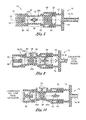
- the flow obstruction 64 can be seen disposed within the bore 20 adjacent the patient end 26 of the flow restrictor 38.
- the flow obstruction 64 is preferably provided with an aerodynamic cross sectional shape.
- the flow obstruction 64 is also preferably positioned to be in general alignment with the pressure jet discharging from the endotracheal tube 16 as best seen in Fig. 9 .
- the flow obstruction 64 promotes uniform velocity across the patient end 26 pressure tap 44b in order to allow accurate pressure measurement of exhalation flow from the patient.
- the bore 20 of the tubular member 18 may include a throat section 36 between the ventilator end 24 and the patient end 26.
- the throat section 36 can be seen as having a reduced cross sectional area relative to the cross sectional area at the ventilator end 24 and/or patient end 26.
- the tubular member 18 may be provided in a variety of alternative shapes and configurations.
- the bore 20 may be provided with a cross sectional shape that is oval or square or another shape.
- the circular cross sectional shape of the bore 20 is believed to provide favorable flow characteristics through the flow sensor and enhance the measurement of pressure at the flow restrictor 38.
- the flow restrictor 38 is diametrically disposed within and bisects the throat section 36. In this regard, the flow restrictor 38 is mounted transversely relative to the central axis 22.
- the flow restrictor 38 is preferably configured to minimize the generation of turbulence at a downstream side of the flow restrictor 38.
- reference to upstream and downstream ends of the flow restrictor 38 is dependent upon the direction of flow. For example, for flow entering the ventilator end 24, the upstream side is closest to the ventilator end 24 while the downstream side of the flow restrictor 38 is closest to the patient end 26.
- the upstream end of the flow restrictor 38 is disposed adjacent the patient end 26 while the downstream end of the flow restrictor 38 is disposed adjacent the ventilator end 24.
- the flow sensor 10 is operative to measure flow in two directions (i.e., bidirectional).
- the upstream end of the flow restrictor 38 is the high pressure end while the downstream end is the low pressure end.
- the difference in pressure between the upstream and downstream ends may be correlated to flow rate based on the known relationship between the square of flow and differential pressure or it can be empirically derived.
- the flow restrictor 38 includes a pair of pressure taps 44a, 44b on opposed ends of the flow restrictor 38.
- Each pressure tap 44a, 44b is defined as a generally open orifice or groove formed along axially opposed ends of the flow restrictor 38.
- the pressure taps 44a, 44b are fluidly connected by a corresponding pair of fluid passageways 48 to a pair of exterior pressure ports 50 on an outer wall of the tubular member 18.
- the fluid passageways 48 extends upwardly from the pressure taps 44a, 44b to the pressure ports 50 wherein a fittings 54 fluidly communicate the pressure at the pressure taps 44a, 44b to the pressure transducer.
- each of the pressure taps 44a, 44b defines a tap height 46 which is preferably symmetrically disposed about the central axis 22 of the bore 20 and which is also preferably equal to or less than an obstruction height 66 of the flow obstruction 64.
- the flow restrictor 38 preferably has an aerodynamic shape in order to minimize disruptions in the flow.
- the flow restrictor 38 is preferably provided with an oblong shape such as a diamond, oval or other suitable cross sectional shape to minimize the generation of turbulence in the flow which may reduce the accuracy of pressure measurements as well as increase the resistance to flow.
- the baffle 56 disposed within the bore 20 at the ventilator end 24.
- the baffle 56 comprises a plurality of vanes 58 which extend radially outwardly from the central axis 22.
- Each of the vanes 58 may be generally axially aligned with the central axis 22.
- the vanes 58 extend radially outwardly from the central axis 22 to the interior surface 28 of the bore 20.
- the baffle 56 is preferably sized and configured to minimize non-axial flow at the pressure taps 44a, 44b. In this regard, the baffle 56 straightens angular or vortex flow entering the flow sensor 10.
- the baffle 56 is specifically adapted to minimize cross flow at the flow restrictor 38 which can otherwise result in erroneous pressure differential measurements.
- the baffle 56 may comprise any number of vanes 58.
- the baffle 56 may comprise a pair of diametrically opposed vanes 58 which collectively bisect the bore 20 at the ventilator end 24.
- the baffle 56 may comprise four of the vanes 58 which are preferably oriented orthogonally (i.e., 90°) relative to one another.
- the baffle 56 comprises eight of the vanes 58 as illustrated in the figures wherein each of the vanes 58 is equally angularly spaced relative to one another.
- the bore 20 may include a taper section 30 located adjacent the baffle 56 wherein the bore 20 tapers radially inwardly along a direction from the ventilator end 24 toward the throat section 36.
- flow entering the ventilator end 24 is constricted as it flows toward the throat section 36.
- the taper section 30 may be a single taper section disposed between the extreme ends of the bore 20 or the taper section 30 may be comprised of progressively steeper first and second tapers 32, 34.
- the first taper 32 may have a half angle (i.e., relative to the central axis 22) of up to approximately 2° as indicated by the reference character 0 1 .
- the second taper 34 is disposed axially inwardly from the first taper 32 and preferably has a half angle, indicated by the reference character 0 2 , of between approximately 12° and approximately 16° (relative to the central axis 22). Transitions between the first and second tapers 32, 34 and the throat section 36 are preferably with a smooth radius in order to avoid disruption in the flow which may generate noise-producing eddies or turbulence.
- Each one of the vanes 58 preferably includes a notch 60 formed on a radially inward side (i.e., along the central axis 22) and opposite the ventilator end 24.
- the formation of the notch 60 may be generally located in the area of the second taper 34 of the bore 20 and allows localized high pressure in any one of the vane 58 passages to be relieved by discharging of any differential (i.e., vane-to-vane) pressure.
- the pressure relief 62 reduces the amount of pneumatic noise and cross flow in the area of the pressure taps 44a, 44b to improve pressure measurement accuracy.
- the flow obstruction 64 interposed between the patient end 26 and the flow restrictor 38.
- the flow obstruction 64 is mounted transverse to the central axis 22 but is oriented perpendicularly relative to the flow restrictor 38 when viewed from an axial direction.
- the flow obstruction 64 bisects the bore 20 and preferably has an aerodynamic cross sectional shape in a transverse direction.
- the shape preferably has an aspect ratio aligned with the central axis 22.
- the aerodynamic cross sectional shape may be a diamond shape as illustrated in the figures or any other alternative shape.
- the flow obstruction 64 may be provided with a teardrop axial cross section wherein the leading edge of the teardrop faces the patient end 26 and the trailing edge of the teardrop faces the ventilator end 24.
- the flow obstruction 64 and flow restrictor 38 are aligned with one another.
- a more preferable relationship is that which is illustrated in the figures wherein the flow obstruction 64 is oriented orthogonally or perpendicularly relative to the flow restrictor 38 when viewed in an axial direction.
- Such an arrangement has been proven to promote better uniformity in the flow velocity across the cross section of the bore 20.
- the flow obstruction 64 defines an obstruction height 66.
- the obstruction height 66 is preferably at least equivalent to the tap height 46 of each one of the pressure taps 44a, 44b such that the pressure jet discharged from the endotracheal tube 16 as shown in Fig. 9 is dispersed into a more uniform velocity profile rather than a direct high velocity pressure jet impinging on the pressure taps 44a, 44b. As was earlier mentioned, the high velocity pressure jet at the pressure taps 44a, 44b would otherwise result in inaccurate flow measurements. It is also contemplated that the obstruction height 66 may be greater than the tap heights 46 of the pressure taps 44a, 44b.
- Fig. 8 shown is an axial cross sectional view of the flow sensor 10 at the patient end 26 and which illustrates an annular groove 68 formed at the patient end 26 for engagement to a standard-sized adapter 70.
- adapter 70 may be a commonly-available airway adapter 70 used for attaching various size patient tubes (i.e., endotracheal tubes 16) to the flow sensor 10.
- the adapter 70 includes a cylindrical extension 72 which is sized and configured to frictionally engage the annular groove 68.
- flow e.g., such as bias flow
- the bias flow may include pneumatic noise such as vibrations, turbulence or asymmetric flow induced by the curved flow path from the mechanical ventilator into the wye fitting.
- Flow from the mechanical ventilator 12 passes through the vanes 58 which extend radially outwardly from the central axis 22.
- the vanes 58 are preferably sized and configured to straighten non-axial flow at the pressure taps 44a, 44b in order to ensure accurate pressure measurement.
- the pressure relief 62 collectively formed by the notches 60 in the vanes 58 is specifically sized and configured to discharge or equalize any differential pressure between the vanes 58 prior to the flow reaching the flow restrictor 38. The flow then passes to the patient via the endotracheal tube 16 such as that which is illustrated in Fig. 4a .
- expired gas is discharged as a high pressure jet from the endotracheal tube 16 as shown in Fig. 9 .
- the high pressure jet enters the flow sensor 10 at the patient end 26 whereupon the flow obstruction 64 causes dispersion of the flow.
- the flow obstruction 64 preferably has a height which is at least equal to the tap height 46 of each of the pressure taps 44a, 44b on the flow restrictor 38 to minimize or eliminate direct impingement of the pressure jet from the endotracheal tube 16 upon the pressure taps 44a, 44b. This geometric relationship between the obstruction height 66 and the tap height 46 prevents an artificially high flow rate measurement.
- the flow obstruction 64 promotes a uniform velocity profile across the bore 20 at the pressure taps 44a, 44b for the flow passing from the patient end 26 and exiting the ventilation end.
- the flow obstruction 64 allows for a flow sensor 10 configuration which reduces deadspace at the patient interface. As was previously mentioned, excessive deadspace is especially undesirable in mechanical ventilation.
Landscapes
- Health & Medical Sciences (AREA)
- Life Sciences & Earth Sciences (AREA)
- Pulmonology (AREA)
- Biomedical Technology (AREA)
- Engineering & Computer Science (AREA)
- Veterinary Medicine (AREA)
- Heart & Thoracic Surgery (AREA)
- Animal Behavior & Ethology (AREA)
- General Health & Medical Sciences (AREA)
- Public Health (AREA)
- Physics & Mathematics (AREA)
- Anesthesiology (AREA)
- Hematology (AREA)
- Emergency Medicine (AREA)
- General Physics & Mathematics (AREA)
- Fluid Mechanics (AREA)
- Pathology (AREA)
- Surgery (AREA)
- Molecular Biology (AREA)
- Medical Informatics (AREA)
- Biophysics (AREA)
- Physiology (AREA)
- Measurement Of The Respiration, Hearing Ability, Form, And Blood Characteristics Of Living Organisms (AREA)
- Measuring Volume Flow (AREA)
- Measuring And Recording Apparatus For Diagnosis (AREA)
Claims (17)
- Bidirektionaler Durchflusssensor (10) zum Messen des Drucks eines dort hindurch verlaufenden Durchflusses, wobei der Durchflusssensor (10) folgendes umfasst:ein hohles röhrenförmiges Element (18) mit einem Ventilatorende (24) und einem Patientenende (26), und wobei das Element eine Bohrung (20) mit einer zentralen Achse definiert, wobei die Bohrung (20) einen Halsabschnitt (36) aufweist, der sich zwischen dem Ventilatorende (24) und dem Patientenende (26) befindet;einen Durchflussbegrenzer (38), der den Halsabschnitt (36) zweiteilt und ein Paar von Druckmesseinrichtungen (44a, 44b) aufweist, die jeweils eine Messeinrichtungshöhe definieren;gekennzeichnet durch eine Durchflusssperre (64), die sich an dem Patientenende (26) befindet und so konfiguriert ist, dass die Durchflusssperre (64) für einen in das Patientenende (26) eintretenden Luftstrom eine gleichmäßige Geschwindigkeit durch die Bohrung (20) an den Druckmesseinrichtungen (44a, 44b) fördert und das direkte Auftreffen des Luftstroms auf die Druckmesseinrichtungen (44a, 44b) verhindert.
- Durchflusssensor (10) nach Anspruch 1, wobei die Durchflusssperre (64) bei einer Betrachtung in eine axiale Richtung senkrecht im Verhältnis zu dem Durchflussbegrenzer (38) ausgerichtet ist.
- Durchflusssensor (10) nach Anspruch 1, wobei die Messeinrichtungshöhe jeder der Druckmesseinrichtungen (44a, 44b) um die zentrale Achse symmetrisch ist.
- Durchflusssensor (10) nach Anspruch 1, wobei die Durchflusssperre (64) einen rautenförmigen axialen Querschnitt aufweist.
- Durchflusssensor (10) nach Anspruch 1, wobei die Durchflusssperre (64) einen tropfenförmigen axialen Querschnitt aufweist.
- Durchflusssensor (10) nach Anspruch 1, wobei der Strömungsbegrenzer (38) einen länglichen axialen Querschnitt aufweist.
- Durchflusssensor (10) nach Anspruch 6, wobei der Strömungsbegrenzer (38) einen rautenförmigen axialen Querschnitt aufweist.
- Durchflusssensor (10) nach Anspruch 1, wobei die Durchflusssperre (64) eine Sperrenhöhe definiert, die so bemessen und konfiguriert ist, dass die Sperrenhöhe nicht kleiner ist als die Messeinrichturtgshöhe.
- Y-Anschlussstück, das den Durchflusssensor (10) nach Anspruch 1 umfasst.
- Bidirektionaler Durchflusssensor (10) nach Anspruch 1, wobei dieser ferner folgendes umfasst:eine Leiteinrichtung (56), die sich an dem Ventilatorende (24) in der Bohrung (20) befindet und eine Mehrzahl von Flügeln (58) umfasst, wobei die Leiteinrichtung (56) so bemessen und konfiguriert ist, dass sie den nicht axialen Strom an den Druckmesseinrichtungen minimiert.
- Durchflusssensor (10) nach Anspruch 10, wobei die Flügel (58) radial ausgerichtet sind.
- Durchflusssensor (10) nach Anspruch 11, wobei die Leiteinrichtung (56) bis zu acht der Flügel (58) umfasst, die in gleicher Winkelstellung im Verhältnis zueinander positioniert sind.
- Durchflusssensor (10) nach Anspruch 11, wobei jeder der Flügel (58) an einer radial einwärts liegenden Seite des Flügels eine Kerbe (60) aufweist, so dass die Kerben (60) gemeinsam eine Druckentlastung definieren.
- Durchflusssensor (10) nach Anspruch 10, wobei die Bohrung (20) einen Verjüngungsabschnitt (30) aufweist, der neben der Leiteinrichtung (56) angeordnet ist und radial einwärts entlang einer Richtung von dem Ventilatorende (24) zu dem Patientenende (26) eine Verjüngung aufweist.
- Durchflusssensor (10) nach Anspruch 10, wobei die Messeinrichtungshöhe jeder der Druckmesseinrichtungen (44a, 44b) um die zentrale Achse symmetrisch ist.
- Durchflusssensor (10) nach Anspruch 10, wobei sich dieser zur Verwendung mit einem mechanischen Ventilator (12) eignet und so konfiguriert ist, dass pneumatisches Rauschen auf unter etwa 0,1 Liter pro Minute (LPM) gehalten wird.
- Y-Anschlussstück, das den Durchflusssensor (10) nach Anspruch 10 umfasst.
Applications Claiming Priority (1)
| Application Number | Priority Date | Filing Date | Title |
|---|---|---|---|
| US12/099,588 US8888711B2 (en) | 2008-04-08 | 2008-04-08 | Flow sensor |
Publications (2)
| Publication Number | Publication Date |
|---|---|
| EP2108927A1 EP2108927A1 (de) | 2009-10-14 |
| EP2108927B1 true EP2108927B1 (de) | 2015-03-25 |
Family
ID=40848052
Family Applications (1)
| Application Number | Title | Priority Date | Filing Date |
|---|---|---|---|
| EP09157566.2A Not-in-force EP2108927B1 (de) | 2008-04-08 | 2009-04-08 | Durchflusssensor |
Country Status (6)
| Country | Link |
|---|---|
| US (3) | US8888711B2 (de) |
| EP (1) | EP2108927B1 (de) |
| JP (1) | JP5904693B2 (de) |
| CN (1) | CN101666664B (de) |
| AU (1) | AU2009201333B2 (de) |
| CA (1) | CA2661589C (de) |
Families Citing this family (84)
| Publication number | Priority date | Publication date | Assignee | Title |
|---|---|---|---|---|
| FR2858236B1 (fr) | 2003-07-29 | 2006-04-28 | Airox | Dispositif et procede de fourniture de gaz respiratoire en pression ou en volume |
| US8302602B2 (en) | 2008-09-30 | 2012-11-06 | Nellcor Puritan Bennett Llc | Breathing assistance system with multiple pressure sensors |
| JP5206975B2 (ja) * | 2009-02-17 | 2013-06-12 | 日本光電工業株式会社 | エアウェイアダプタ、呼吸気濃度センサ、および呼吸気流量センサ |
| US8434479B2 (en) | 2009-02-27 | 2013-05-07 | Covidien Lp | Flow rate compensation for transient thermal response of hot-wire anemometers |
| CH701755B1 (de) * | 2009-09-07 | 2014-03-14 | Hamilton Medical Ag | Durchflussmessfühler. |
| US8439037B2 (en) | 2009-12-01 | 2013-05-14 | Covidien Lp | Exhalation valve assembly with integrated filter and flow sensor |
| US8469030B2 (en) * | 2009-12-01 | 2013-06-25 | Covidien Lp | Exhalation valve assembly with selectable contagious/non-contagious latch |
| US8469031B2 (en) | 2009-12-01 | 2013-06-25 | Covidien Lp | Exhalation valve assembly with integrated filter |
| US8439036B2 (en) | 2009-12-01 | 2013-05-14 | Covidien Lp | Exhalation valve assembly with integral flow sensor |
| EP2371410B1 (de) * | 2010-03-29 | 2016-10-12 | General Electric Company | Anordnung und Verfahren zur Beatmung der Lungen |
| WO2012088613A1 (en) * | 2010-12-29 | 2012-07-05 | Sensirion Ag | Apparatus for measuring the flow of a fluid |
| US9629971B2 (en) | 2011-04-29 | 2017-04-25 | Covidien Lp | Methods and systems for exhalation control and trajectory optimization |
| US9364624B2 (en) | 2011-12-07 | 2016-06-14 | Covidien Lp | Methods and systems for adaptive base flow |
| US9498589B2 (en) | 2011-12-31 | 2016-11-22 | Covidien Lp | Methods and systems for adaptive base flow and leak compensation |
| AU2013232848B2 (en) | 2012-03-15 | 2018-03-22 | Fisher & Paykel Healthcare Limited | Respiratory gas humidification system |
| AU2013234264A1 (en) * | 2012-03-15 | 2014-10-02 | Institutt For Energiteknikk | Tracer based flow measurement |
| WO2013162386A1 (en) | 2012-04-27 | 2013-10-31 | Fisher & Paykel Healthcare Limited | Usability features for respiratory humidification system |
| US9144658B2 (en) | 2012-04-30 | 2015-09-29 | Covidien Lp | Minimizing imposed expiratory resistance of mechanical ventilator by optimizing exhalation valve control |
| USD757242S1 (en) * | 2012-05-15 | 2016-05-24 | Geoffrey Nicholas Maksym | Handheld respiratory airway device |
| GB2505689B (en) * | 2012-09-07 | 2018-11-21 | Intersurgical Ag | Improvements to valve assemblies |
| EP4316559A3 (de) * | 2012-12-04 | 2024-03-27 | Fisher & Paykel Healthcare Limited | Medizinische schläuche und verfahren zur herstellung |
| USD727492S1 (en) * | 2012-12-06 | 2015-04-21 | Koninklijke Philips N.V. | Disposable airway adapter for respiratory gas monitoring |
| JP6265363B2 (ja) * | 2013-01-11 | 2018-01-24 | 国立大学法人名古屋大学 | 気管内挿管チューブ装着器具及びその製造方法 |
| US10006573B2 (en) | 2013-02-20 | 2018-06-26 | Fisher & Paykel Healthcare Limited | Connector for multiple sized connections |
| USD731049S1 (en) | 2013-03-05 | 2015-06-02 | Covidien Lp | EVQ housing of an exhalation module |
| USD693001S1 (en) | 2013-03-08 | 2013-11-05 | Covidien Lp | Neonate expiratory filter assembly of an exhalation module |
| USD731048S1 (en) | 2013-03-08 | 2015-06-02 | Covidien Lp | EVQ diaphragm of an exhalation module |
| USD701601S1 (en) | 2013-03-08 | 2014-03-25 | Covidien Lp | Condensate vial of an exhalation module |
| USD744095S1 (en) | 2013-03-08 | 2015-11-24 | Covidien Lp | Exhalation module EVQ internal flow sensor |
| USD731065S1 (en) | 2013-03-08 | 2015-06-02 | Covidien Lp | EVQ pressure sensor filter of an exhalation module |
| USD736905S1 (en) | 2013-03-08 | 2015-08-18 | Covidien Lp | Exhalation module EVQ housing |
| USD692556S1 (en) | 2013-03-08 | 2013-10-29 | Covidien Lp | Expiratory filter body of an exhalation module |
| US9950135B2 (en) | 2013-03-15 | 2018-04-24 | Covidien Lp | Maintaining an exhalation valve sensor assembly |
| US10286175B2 (en) * | 2013-05-17 | 2019-05-14 | Resmed Paris Sas | Flow diffuser and sound cone |
| JP5861665B2 (ja) * | 2013-05-24 | 2016-02-16 | 株式会社デンソー | 呼吸機能検査装置及びプログラム並びに記録媒体 |
| CN108514674B (zh) | 2013-09-13 | 2021-12-24 | 费雪派克医疗保健有限公司 | 用于加湿系统的连接 |
| WO2015119515A1 (en) | 2014-02-07 | 2015-08-13 | Fisher & Paykel Healthcare Limited | Respiratory humidification system |
| CA2941086C (en) * | 2014-02-28 | 2023-02-28 | Breas Medical Ab | Flow sensor for ventilator |
| EP4670770A3 (de) | 2014-06-03 | 2026-01-07 | Fisher & Paykel Healthcare Limited | Befeuchtungskammer für eine atemtherapievorrichtung |
| JP6338487B2 (ja) * | 2014-08-04 | 2018-06-06 | 日本電産コパル電子株式会社 | Cpap装置 |
| CN104721929B (zh) * | 2015-03-24 | 2016-08-31 | 湖南明康中锦医疗科技发展有限公司 | 一种呼吸机截流装置 |
| US10245406B2 (en) | 2015-03-24 | 2019-04-02 | Ventec Life Systems, Inc. | Ventilator with integrated oxygen production |
| US11247015B2 (en) | 2015-03-24 | 2022-02-15 | Ventec Life Systems, Inc. | Ventilator with integrated oxygen production |
| USD775345S1 (en) | 2015-04-10 | 2016-12-27 | Covidien Lp | Ventilator console |
| CN104840201A (zh) * | 2015-05-14 | 2015-08-19 | 天津大学 | 一种主流式人呼吸流量实时监测装置与监测方法 |
| US11890089B1 (en) | 2015-07-28 | 2024-02-06 | Thorasys Thoracic Medical Systems Inc. | Flowmeter for airway resistance measurements |
| CN105105750A (zh) * | 2015-09-15 | 2015-12-02 | 天津大学 | 主流式人呼吸流量和二氧化碳浓度同步监测装置与方法 |
| JP6198882B1 (ja) * | 2016-04-05 | 2017-09-20 | 日本精密測器株式会社 | 呼気検査装置 |
| US10773049B2 (en) | 2016-06-21 | 2020-09-15 | Ventec Life Systems, Inc. | Cough-assist systems with humidifier bypass |
| CN107242874B (zh) * | 2017-05-26 | 2024-08-09 | 浙江亿联康医疗科技有限公司 | 用于肺功能测定的流量传感器、肺功能测试仪及应用 |
| US20190254567A1 (en) * | 2016-09-03 | 2019-08-22 | Cipla Limited | Device for measuring respiratory parameters of a patient |
| AU2017371480B2 (en) | 2016-12-07 | 2022-11-03 | Fisher And Paykel Healthcare Limited | Sensing arrangements for medical devices |
| CN108458757A (zh) * | 2017-02-17 | 2018-08-28 | 上海轻叶工程科技有限公司 | 多孔板、流量测量仪、高低压管道系统及控制方法 |
| USD862643S1 (en) | 2017-02-23 | 2019-10-08 | Hill-Rom Services Pte. Ltd. | Flow control apparatus |
| DE102017208421A1 (de) * | 2017-05-18 | 2018-11-22 | Hamilton Medical Ag | Exspirationsventil für eine Beatmungsvorrichtung mit geräuschminderndem Strömungswiderstand |
| CN107049317A (zh) * | 2017-05-26 | 2017-08-18 | 台州亿联健医疗科技有限公司 | 在持续呼吸气检测过程中判断呼气或吸气的方法 |
| CN108931272B (zh) * | 2017-05-27 | 2021-12-31 | 深圳市美好创亿医疗科技股份有限公司 | 多孔压差流量传感器及肺功能仪 |
| CN116236181A (zh) * | 2017-08-17 | 2023-06-09 | 浙江亿联康医疗科技有限公司 | 肺功能仪 |
| JP6389975B1 (ja) * | 2018-02-26 | 2018-09-12 | チェスト株式会社 | フローセンサ及び呼吸機能検査装置 |
| USD867913S1 (en) * | 2018-03-16 | 2019-11-26 | General Electric Company | Flow sensor |
| DE102018204800A1 (de) * | 2018-03-28 | 2019-10-02 | Hamilton Medical Ag | Differenzdruck-Durchflusssensor für Beatmungsvorrichtungen mit verbesserter Entwässerung |
| CN114504714B (zh) | 2018-05-13 | 2026-02-10 | 万泰生命系统公司 | 使用便携式氧气浓缩器的便携式医用呼吸机系统 |
| WO2020021492A1 (de) * | 2018-07-27 | 2020-01-30 | Imt Analytics Ag | Atemstromsensor |
| BR102018067660A2 (pt) * | 2018-09-03 | 2020-03-17 | Salvus Tecnologia Ltda - Epp | Dispositivo para medição de fluxo por diferença de pressão para gases |
| KR20210074359A (ko) * | 2018-10-15 | 2021-06-21 | 티에스아이 인코포레이티드 | 흐름 방향을 모니터링하기 위한 장치, 시스템 및 방법 및 흐름 방향 센서를 제조하기 위한 방법 |
| JP7343762B2 (ja) * | 2019-09-27 | 2023-09-13 | ダイキン工業株式会社 | 呼吸検知装置、及び、酸素濃縮装置 |
| USD1031014S1 (en) * | 2019-10-07 | 2024-06-11 | Raumedic Ag | Respiration device |
| US11896767B2 (en) | 2020-03-20 | 2024-02-13 | Covidien Lp | Model-driven system integration in medical ventilators |
| CN115379872B (zh) * | 2020-04-16 | 2025-10-31 | 尼奥雷斯公司 | 用于呼吸支持的装置和系统 |
| CN115427096B (zh) * | 2020-04-16 | 2025-11-04 | 尼奥雷斯公司 | 用于呼吸支持的装置和系统 |
| CN111991667B (zh) * | 2020-09-03 | 2021-03-12 | 青岛大学附属医院 | 一种麻醉科用多通道口咽部通气装置 |
| JP2023548463A (ja) | 2020-11-06 | 2023-11-17 | ベンテック ライフ システムズ, インコーポレイテッド | 呼吸療法データ管理システム、デバイス、および方法 |
| US11371867B2 (en) * | 2020-11-16 | 2022-06-28 | Rosemount Inc. | Fluid flow obstruction device for a process fluid flow measurement device |
| EP4011425B1 (de) * | 2020-12-11 | 2024-12-04 | Oli - Sistemas Sanitarios, S.A. | Multifunktionsverbinder für beatmungsmasken |
| US11733144B2 (en) * | 2020-12-14 | 2023-08-22 | Caterpillar Inc. | Convertible housing assembly for a particle sensor |
| EP4262950A4 (de) * | 2020-12-18 | 2024-10-30 | Fisher & Paykel Healthcare Limited | Atemverbinderanordnung und atemunterstützungssystem |
| CA3206169A1 (en) | 2020-12-21 | 2022-06-30 | Ventec Life Systems, Inc. | Ventilator systems with integrated oxygen delivery, and associated devices and methods |
| US20220347418A1 (en) * | 2021-04-21 | 2022-11-03 | Seabeck Holdings, Llc | Pulsed oxygen system and process |
| CN114271810B (zh) * | 2021-12-21 | 2023-05-12 | 中国科学院空天信息创新研究院 | 球型阻塞节流装置以及应用球型阻塞节流装置的肺量计 |
| US20230355910A1 (en) * | 2022-05-04 | 2023-11-09 | Oli - Sistemas Sanitarios, S.A. | Multifunction connector for ventilation face masks |
| US12443208B2 (en) | 2023-02-08 | 2025-10-14 | Rain Bird Corporation | Control zone devices, systems and methods |
| DE102023104003A1 (de) * | 2023-02-17 | 2024-08-22 | Hamilton Medical Ag | Verbindungsstecker für den Anschluss eines pneumatischen Durchflusssensors an ein Beatmungsgerät, Beatmungssystem, und Verfahren zum Vorbereiten eines Beatmungssystems |
| SE2350835A1 (en) * | 2023-07-04 | 2024-05-31 | Maquet Critical Care Ab | Combined flow sensor and check valve |
| US12498049B2 (en) | 2024-03-29 | 2025-12-16 | Rain Bird Corporation | Zone control devices, systems and methods |
Family Cites Families (231)
| Publication number | Priority date | Publication date | Assignee | Title |
|---|---|---|---|---|
| US56614A (en) * | 1866-07-24 | Improvement in cross-heads for blowers | ||
| US587907A (en) | 1897-08-10 | Piston for rotary pumps | ||
| US1769153A (en) * | 1928-03-07 | 1930-07-01 | Meyer William Warren | Rotary blower or pump |
| US2014932A (en) | 1933-03-17 | 1935-09-17 | Gen Motors Corp | Roots blower |
| US2787999A (en) * | 1951-09-13 | 1957-04-09 | Bennett Vivian Ray | Respiratory ventilation meter |
| US3089638A (en) * | 1958-12-01 | 1963-05-14 | Dresser Ind | Impellers for fluid handling apparatus of the rotary positive displacement type |
| US3094274A (en) * | 1960-04-29 | 1963-06-18 | Harris A Thompson | Artificial respirator apparatus |
| US3196680A (en) * | 1962-01-03 | 1965-07-27 | Itt | Flow tubes |
| GB1089203A (en) | 1963-08-15 | 1967-11-01 | Int Combustion Holdings Ltd | Improvements in or relating to fluid flow measuring devices |
| US3371856A (en) * | 1966-03-24 | 1968-03-05 | Fuller Co | Modified cycloidal impeller |
| US3459395A (en) | 1967-08-16 | 1969-08-05 | Ambac Ind | Shock isolating means |
| AT307188B (de) * | 1969-11-21 | 1973-05-10 | Fumagalli Giovanni | Einrichtung zur Regelung des Durchlaßquerschnittes eines einen Unterdruck begrenzenden Ventiles |
| US3941206A (en) * | 1974-05-08 | 1976-03-02 | Burgess Industries Incorporated | Noise attenuating snubber |
| US4121578A (en) | 1976-10-04 | 1978-10-24 | The Bendix Corporation | Physiological responsive control for an oxygen regulator |
| SE414814B (sv) | 1976-10-19 | 1980-08-18 | Atlas Copco Ab | Rotorpar for en blasmaskin |
| US4323064A (en) * | 1976-10-26 | 1982-04-06 | Puritan-Bennett Corporation | Volume ventilator |
| US4080103A (en) * | 1977-01-12 | 1978-03-21 | Bird F M | Portable air compressor system for respirator |
| DE2731799C3 (de) | 1977-07-14 | 1984-10-18 | Reich Spezialmaschinen GmbH, 7440 Nürtingen | Kantenanleimmaschine mit einer Schmelzkammer |
| US4215977A (en) | 1977-11-14 | 1980-08-05 | Calspan Corporation | Pulse-free blower |
| US4220219A (en) | 1978-09-14 | 1980-09-02 | Flugger Ray T | Lightweight muffler and method for muffling noise |
| US4239039A (en) | 1979-02-28 | 1980-12-16 | Thompson Harris A | Dual control valve for positive pressure artificial respiration apparatus |
| US4267899A (en) * | 1979-08-31 | 1981-05-19 | Donaldson Company, Inc. | Muffler assembly |
| SE427062B (sv) | 1980-08-28 | 1983-02-28 | Stal Refrigeration Ab | Drivanordning for en kompressor av rotationstyp |
| IT1155626B (it) * | 1982-02-23 | 1987-01-28 | Fiat Auto Spa | Compressore volumetrico rotativo del tipo roots |
| US4448192A (en) * | 1982-03-05 | 1984-05-15 | Hewlett Packard Company | Medical ventilator device parametrically controlled for patient ventilation |
| US4495947A (en) * | 1982-09-23 | 1985-01-29 | Imasco-Cdc Research Foundation | High speed medical ventilator |
| US4595349A (en) * | 1983-06-20 | 1986-06-17 | Eaton Corp. | Supercharger rotor, shaft, and gear arrangement |
| JPS6075793A (ja) * | 1983-09-30 | 1985-04-30 | Aisin Seiki Co Ltd | ル−ツ型ブロア |
| DE3414039A1 (de) | 1984-04-13 | 1985-10-17 | Aerzener Maschinenfabrik Gmbh, 3251 Aerzen | Roots-kompressor zum komprimieren von gasfoermigem foerdermedium |
| US4564345A (en) * | 1984-09-04 | 1986-01-14 | Eaton Corporation | Supercharger with reduced noise |
| US4638672A (en) * | 1984-09-11 | 1987-01-27 | Ametek, Inc. | Fluid flowmeter |
| US4609335A (en) | 1984-09-20 | 1986-09-02 | Eaton Corporation | Supercharger with reduced noise and improved efficiency |
| US4686999A (en) | 1985-04-10 | 1987-08-18 | Tri Fund Research Corporation | Multi-channel ventilation monitor and method |
| US4768934A (en) | 1985-11-18 | 1988-09-06 | Eaton Corporation | Port arrangement for rotary positive displacement blower |
| US4662912A (en) * | 1986-02-27 | 1987-05-05 | Perkins Lynn W | Air purifying and stabilizing blower |
| US4697125A (en) | 1986-03-24 | 1987-09-29 | Performance Controls, Inc. | Method and apparatus for determining shaft position and for providing commutation signals |
| US4673058A (en) * | 1986-05-09 | 1987-06-16 | G Enterprises Limited | High performance automotive muffler |
| DE3620792A1 (de) | 1986-06-20 | 1987-12-23 | Wankel Gmbh | Aussenachsiges rotationskolbengeblaese |
| US4715234A (en) | 1986-07-18 | 1987-12-29 | Daniel Industries, Inc. | Self-cleaning and self-lubricating fluid flowmeter |
| US4702240A (en) | 1986-07-22 | 1987-10-27 | Bear Medical Systems, Inc. | Demand-responsive gas blending system for medical ventilator |
| US4846302A (en) * | 1986-08-08 | 1989-07-11 | Tenneco Inc. | Acoustic muffler |
| US4794922A (en) * | 1986-11-04 | 1989-01-03 | Bird Products Corporation | Ventilator manifold |
| US5199424A (en) | 1987-06-26 | 1993-04-06 | Sullivan Colin E | Device for monitoring breathing during sleep and control of CPAP treatment that is patient controlled |
| JPS6415485A (en) | 1987-07-07 | 1989-01-19 | Fuji Heavy Ind Ltd | Root's blower |
| US4867151A (en) | 1987-10-19 | 1989-09-19 | Bird F M | Mobile self-contained ventilator |
| US4841781A (en) | 1987-12-04 | 1989-06-27 | Schlumberger Industries, Inc. | Flow rectifier for vortex flowmeter |
| US4957107A (en) | 1988-05-10 | 1990-09-18 | Sipin Anatole J | Gas delivery means |
| US4844044A (en) * | 1988-06-27 | 1989-07-04 | Eaton Corporation | Torsion damping mechanism for a supercharger |
| FI84757C (fi) * | 1988-12-12 | 1992-01-10 | Instrumentarium Oy | Foer stroemningsmaetning avsett gasens stroemning begraensande och styrande organ. |
| JP2761233B2 (ja) | 1989-02-17 | 1998-06-04 | 富士重工業株式会社 | ルーツ型ブロワ |
| JP2770183B2 (ja) | 1989-02-28 | 1998-06-25 | アイシン精機株式会社 | 容積型圧縮機 |
| US5134995A (en) | 1989-05-19 | 1992-08-04 | Puritan-Bennett Corporation | Inspiratory airway pressure system with admittance determining apparatus and method |
| US4938670A (en) | 1989-10-02 | 1990-07-03 | Tocew Lee | Rotary fluid machine |
| US5161525A (en) | 1990-05-11 | 1992-11-10 | Puritan-Bennett Corporation | System and method for flow triggering of pressure supported ventilation |
| US5335651A (en) | 1990-05-16 | 1994-08-09 | Hill-Rom Company, Inc. | Ventilator and care cart each capable of nesting within and docking with a hospital bed base |
| US5237987A (en) | 1990-06-07 | 1993-08-24 | Infrasonics, Inc. | Human lung ventilator system |
| DE59005764D1 (de) | 1990-08-27 | 1994-06-23 | Leybold Ag | Rotor für eine Wälzkolbenvakuumpumpe. |
| US5211170A (en) * | 1991-04-01 | 1993-05-18 | Press Roman J | Portable emergency respirator |
| US5145349A (en) | 1991-04-12 | 1992-09-08 | Dana Corporation | Gear pump with pressure balancing structure |
| US5239994A (en) | 1991-05-10 | 1993-08-31 | Bunnell Incorporated | Jet ventilator system |
| US5131829A (en) | 1991-06-19 | 1992-07-21 | Eaton Corporation | Trapped volume vent means for meshing lobes of roots-type supercharger |
| US5237984A (en) | 1991-06-24 | 1993-08-24 | Xomed-Treace Inc. | Sheath for endoscope |
| JP3217391B2 (ja) | 1991-07-01 | 2001-10-09 | 株式会社東芝 | 電力変換装置 |
| US5222148A (en) * | 1992-04-29 | 1993-06-22 | General Motors Corporation | Active noise control system for attenuating engine generated noise |
| US5350888A (en) | 1992-05-01 | 1994-09-27 | Tennessee Gas Pipeline Company | Broad band low frequency passive muffler |
| US5535633A (en) | 1992-09-23 | 1996-07-16 | Korr Medical Technologies, Inc. | Differential pressure sensor for respiratory monitoring |
| US5379650A (en) * | 1992-09-23 | 1995-01-10 | Korr Medical Technologies Inc. | Differential pressure sensor for respiratory monitoring |
| US5398676A (en) * | 1993-09-30 | 1995-03-21 | Press; Roman J. | Portable emergency respirator |
| BR9304638A (pt) | 1993-12-06 | 1995-07-25 | Intermed Equipamento Medico Ho | Sistema de controle de ciclo respiratório |
| EP0667169B1 (de) | 1994-01-12 | 1999-04-07 | Société d'Applications Industrielles Medicales et Electroniques ( SAIME) | Beatmungsgerät mit einem Atemunterstützungsverfahren unter erniedrigtem Druck |
| US5439358A (en) | 1994-01-27 | 1995-08-08 | Weinbrecht; John F. | Recirculating rotary gas compressor |
| US5760348A (en) * | 1994-04-28 | 1998-06-02 | Heuser; Stephen Glen | Noise attenuating apparatus |
| US5632270A (en) * | 1994-09-12 | 1997-05-27 | Puritan-Bennett Corporation | Method and apparatus for control of lung ventilator exhalation circuit |
| US5554020A (en) * | 1994-10-07 | 1996-09-10 | Ford Motor Company | Solid lubricant coating for fluid pump or compressor |
| DE69533597T2 (de) * | 1994-10-14 | 2005-10-06 | Bird Products Corporation, Palm Springs | Ausatmungsventil mit Messwertaufnehmer für die Ausatmungsströmung |
| US5664563A (en) | 1994-12-09 | 1997-09-09 | Cardiopulmonary Corporation | Pneumatic system |
| US5598838A (en) | 1995-04-07 | 1997-02-04 | Healthdyne Technologies, Inc. | Pressure support ventilatory assist system |
| US5577152A (en) | 1995-04-12 | 1996-11-19 | Chen; Ruey-Zon | Motor assembly |
| US5702240A (en) | 1995-05-05 | 1997-12-30 | Tuthill Corporation | Rotary positive displacement blower having a diverging outlet part |
| JPH08313312A (ja) * | 1995-05-22 | 1996-11-29 | Aichi Tokei Denki Co Ltd | タービン式流量計 |
| US5931159A (en) | 1995-09-09 | 1999-08-03 | Origin Medical Instrument Co., Ltd. | Lung ventilator |
| US5635810A (en) | 1995-09-20 | 1997-06-03 | Analog Devices, Inc. | Control system for a permanent magnet synchronous motor |
| AUPN616795A0 (en) | 1995-10-23 | 1995-11-16 | Rescare Limited | Ipap duration in bilevel cpap or assisted respiration treatment |
| US20010044588A1 (en) | 1996-02-22 | 2001-11-22 | Mault James R. | Monitoring system |
| JP3707699B2 (ja) | 1996-02-27 | 2005-10-19 | ヘンク ダブリュー コスター | 追加的ガス投与器を有する換気システム |
| IT1283244B1 (it) | 1996-03-14 | 1998-04-16 | Rotoincisa Srl | Procedimento per la preparazione delle camicie da fotoincidere, sfilabili dei cilindri per la stampa rotocalco e camicie ottenute |
| DE19617738C1 (de) * | 1996-05-03 | 1997-06-19 | Draegerwerk Ag | Atemstromsensor |
| US5823186A (en) | 1996-06-20 | 1998-10-20 | Dragerwerk Ag | Respirator |
| JP2884067B2 (ja) | 1996-06-28 | 1999-04-19 | 株式会社アンレット | ルーツ式ブロワー |
| US5687717A (en) | 1996-08-06 | 1997-11-18 | Tremont Medical, Inc. | Patient monitoring system with chassis mounted or remotely operable modules and portable computer |
| AUPO163896A0 (en) | 1996-08-14 | 1996-09-05 | Resmed Limited | Determination of respiratory airflow |
| US5701883A (en) | 1996-09-03 | 1997-12-30 | Respironics, Inc. | Oxygen mixing in a blower-based ventilator |
| AUPO247496A0 (en) | 1996-09-23 | 1996-10-17 | Resmed Limited | Assisted ventilation to match patient respiratory need |
| US5783782A (en) | 1996-10-29 | 1998-07-21 | Tenneco Automotive Inc. | Multi-chamber muffler with selective sound absorbent material placement |
| DE19647058C2 (de) * | 1996-11-14 | 1999-05-20 | Draegerwerk Ag | Beatmungsgerät mit inspiratorischer Frischgasdosierung |
| JP3573897B2 (ja) * | 1997-01-24 | 2004-10-06 | 株式会社日立製作所 | 内燃機関の吸気系及びそれを備える内燃機関の制御システム |
| IT1290106B1 (it) * | 1997-03-17 | 1998-10-19 | Finder Pompe Spa | Soffiante volumetrica con coperchi dotati di condotto di collegamento con il collettore di mandata |
| JP2001516623A (ja) * | 1997-09-19 | 2001-10-02 | レスピロニックス・インコーポレイテッド | 医療用呼吸器 |
| US5831223A (en) | 1997-09-24 | 1998-11-03 | Kesselring; Stephen H. | Self-tuning exhaust muffler |
| US6591835B1 (en) | 1997-09-26 | 2003-07-15 | Airon Corporation | Pneumatically controlled multifunction medical ventilator |
| US6571792B1 (en) * | 1997-10-15 | 2003-06-03 | Datex-Ohmeda, Inc. | Smart modular anesthesia respiratory system |
| JP3615371B2 (ja) | 1997-10-16 | 2005-02-02 | ウエツトマスター株式会社 | 風量測定装置 |
| SE9704663D0 (sv) | 1997-12-15 | 1997-12-15 | Siemens Elema Ab | Ventilator system |
| US6076523A (en) | 1998-01-15 | 2000-06-20 | Nellcor Puritan Bennett | Oxygen blending in a piston ventilator |
| US5918597A (en) | 1998-01-15 | 1999-07-06 | Nellcor Puritan Bennett | Peep control in a piston ventilator |
| US6164412A (en) | 1998-04-03 | 2000-12-26 | Arvin Industries, Inc. | Muffler |
| US6125844A (en) | 1998-04-30 | 2000-10-03 | Westwood Biomedical | Portable oxygen based drug delivery system |
| US6102038A (en) | 1998-05-15 | 2000-08-15 | Pulmonetic Systems, Inc. | Exhalation valve for mechanical ventilator |
| US6084376A (en) | 1998-06-09 | 2000-07-04 | Aspen Motion Technologies, Inc. | Low cost resolver system |
| JP2992513B1 (ja) | 1998-07-16 | 1999-12-20 | 株式会社 ビーテック | サイレンサ |
| US6631716B1 (en) | 1998-07-17 | 2003-10-14 | The Board Of Trustees Of The Leland Stanford Junior University | Dynamic respiratory control |
| US6099277A (en) | 1998-08-12 | 2000-08-08 | Dresser Industries, Inc. | Gas blower and method utilizing recirculation openings |
| US6155257A (en) | 1998-10-07 | 2000-12-05 | Cprx Llc | Cardiopulmonary resuscitation ventilator and methods |
| US6152135A (en) | 1998-10-23 | 2000-11-28 | Pulmonetic Systems, Inc. | Ventilator system |
| US6354558B1 (en) * | 1998-11-20 | 2002-03-12 | Carrier Corporation | Compressor mounting |
| US6279574B1 (en) | 1998-12-04 | 2001-08-28 | Bunnell, Incorporated | Variable flow and pressure ventilation system |
| AUPQ102999A0 (en) * | 1999-06-18 | 1999-07-08 | Resmed Limited | A connector for a respiratory mask and a respiratory mask |
| US7431031B2 (en) | 1998-12-22 | 2008-10-07 | Ric Investments, Llc | Insufflation system and method |
| GB2362108A (en) | 1999-02-03 | 2001-11-14 | Univ Florida | Method and apparatus for nullifying the imposed work of breathing |
| AU2506300A (en) | 1999-02-04 | 2000-08-25 | Versamed Medical Systems Ltd. | Computer-controlled portable ventilator |
| AU3448900A (en) | 1999-04-07 | 2000-10-23 | Event Medical Limited | Breathing apparatus |
| US7086366B1 (en) | 1999-04-20 | 2006-08-08 | Metaldyne Machining And Assembly Company, Inc. | Energy efficient fluid pump |
| US6672300B1 (en) * | 1999-06-23 | 2004-01-06 | Graham Cameron Grant | Respiration assistor |
| US6615831B1 (en) | 1999-07-02 | 2003-09-09 | Respironics, Inc. | Pressure support system and method and a pressure control valve for use in such system and method |
| SE9902709D0 (sv) * | 1999-07-15 | 1999-07-15 | Siemens Elema Ab | Förfarande för styrning av en exspirationsventil i en ventilator |
| US6708690B1 (en) * | 1999-09-03 | 2004-03-23 | Respironics, Inc. | Apparatus and method for providing high frequency variable pressure to a patient |
| US7225809B1 (en) * | 1999-11-01 | 2007-06-05 | Ric Investments, Llc | Method and apparatus for monitoring and controlling a medical device |
| US6837260B1 (en) * | 1999-11-02 | 2005-01-04 | Respironics, Inc. | Pressure support system having a two-piece assembly |
| US6629934B2 (en) | 2000-02-02 | 2003-10-07 | Healthetech, Inc. | Indirect calorimeter for medical applications |
| JP3442024B2 (ja) | 2000-02-29 | 2003-09-02 | 株式会社日立製作所 | モータ駆動回路及びモータ駆動方法、並びに半導体集積回路装置 |
| DE10013960C2 (de) | 2000-03-21 | 2002-08-01 | Draeger Medical Ag | Radialgebläse zu Beatmungszwecken mit verminderter Schallemission |
| AU2001251667A1 (en) | 2000-04-17 | 2001-10-30 | Scott Technologies, Inc. | Respiratory mask and service module |
| US6637430B1 (en) | 2000-06-16 | 2003-10-28 | Ponwell Enterprises Limited | Respiratory delivery system with power/medicament recharge assembly |
| GB0014713D0 (en) | 2000-06-16 | 2000-08-09 | 3M Innovative Properties Co | Pressure regulator for a respirator system |
| DE10035054C1 (de) * | 2000-07-19 | 2001-10-25 | Draeger Medical Ag | Atemstromsensor |
| US6651658B1 (en) | 2000-08-03 | 2003-11-25 | Sequal Technologies, Inc. | Portable oxygen concentration system and method of using the same |
| US6691702B2 (en) * | 2000-08-03 | 2004-02-17 | Sequal Technologies, Inc. | Portable oxygen concentration system and method of using the same |
| WO2002015781A1 (en) * | 2000-08-18 | 2002-02-28 | Masimo Corporation | Dual-mode pulse oximeter |
| US6626175B2 (en) | 2000-10-06 | 2003-09-30 | Respironics, Inc. | Medical ventilator triggering and cycling method and mechanism |
| US6558137B2 (en) * | 2000-12-01 | 2003-05-06 | Tecumseh Products Company | Reciprocating piston compressor having improved noise attenuation |
| EP1355689B1 (de) * | 2000-12-29 | 2010-05-26 | Resmed Ltd. | Charakterisierung von maskensystemen |
| US7073499B1 (en) | 2001-02-06 | 2006-07-11 | Injet Digital Aerosols Limited | Inhaler with airflow regulation |
| US6571796B2 (en) * | 2001-02-08 | 2003-06-03 | University Of Florida | Tracheal pressure ventilation respiratory system |
| US6666209B2 (en) | 2001-02-20 | 2003-12-23 | 3M Innovative Properties Company | Method and system of calibrating air flow in a respirator system |
| US20020134378A1 (en) | 2001-03-26 | 2002-09-26 | Finnegan Linda A. | Sound dampening housing for respiratory assist devices |
| US20030208113A1 (en) | 2001-07-18 | 2003-11-06 | Mault James R | Closed loop glycemic index system |
| EP1286458A1 (de) * | 2001-08-22 | 2003-02-26 | Pumpenfabrik Ernst Vogel Gesellschaft m.b.H. | Verfahren und Vorrichtung zur Regelung von Kreiselarbeitsmaschinen |
| US7168429B2 (en) * | 2001-10-12 | 2007-01-30 | Ric Investments, Llc | Auto-titration pressure support system and method of using same |
| DE10262337B4 (de) | 2001-11-19 | 2015-04-02 | Denso Corporation | Gerät zum Messen der Durchflussmenge |
| US6726176B2 (en) * | 2002-01-02 | 2004-04-27 | Fisher Controls International, Inc. | Stepped butterfly valve |
| US6745770B2 (en) * | 2002-01-08 | 2004-06-08 | Resmed Limited | Flow diverter for controlling the pressure and flow rate in a CPAP device |
| US7032589B2 (en) * | 2002-01-23 | 2006-04-25 | The Johns Hopkins University | Portable ventilator |
| WO2003064009A1 (en) | 2002-01-31 | 2003-08-07 | Airsep Corporation | Portable oxygen concentrator |
| US6968842B1 (en) | 2002-04-03 | 2005-11-29 | Ric Investments, Inc. | Measurement of a fluid parameter in a pressure support system |
| EP1505937A1 (de) * | 2002-04-22 | 2005-02-16 | Jane Homan | Modulares biologisches sicherheits-gerät und system |
| FR2842903B1 (fr) * | 2002-07-23 | 2004-11-19 | Schlumberger Services Petrol | Dispositif a helice pour acquisition de donnees dans un ecoulement |
| WO2004008961A1 (en) | 2002-07-24 | 2004-01-29 | Versamed Medical Systems Ltd. | Respiratory flow sensor |
| CA2982090C (en) * | 2002-09-17 | 2020-02-25 | Fisher & Paykel Healthcare Limited | Apparatus for delivering humidified gases |
| WO2004032727A2 (en) | 2002-10-11 | 2004-04-22 | The Regents Of The University Of California | Bymixer apparatus and method for fast-response, adjustable measurement of mixed gas fractions in ventilation circuits |
| US6744230B2 (en) | 2002-10-29 | 2004-06-01 | Honeywell International Inc. | Method and apparatus for fine resolution brushless motor control |
| AU2003280685A1 (en) * | 2002-10-31 | 2004-05-25 | Nsk Ltd. | Electric power steering device |
| US6752240B1 (en) * | 2002-11-05 | 2004-06-22 | Brunswick Corporation | Sound attenuator for a supercharged marine propulsion device |
| US20040147818A1 (en) | 2002-11-18 | 2004-07-29 | Andrew Levy | Portable system for monitoring and processing patient parameters in multiple oprational modes |
| US20040226562A1 (en) | 2002-12-06 | 2004-11-18 | Bordewick Steven S. | Blower assembly for CPAP |
| AU2003293415A1 (en) * | 2002-12-12 | 2004-07-09 | Airsep Corporation | Portable hypoxic apparatus |
| WO2004082751A1 (de) | 2003-03-17 | 2004-09-30 | Map Medizin-Technologie Gmbh | Verfahren und anordnung zur titration physiologischer messsignale im zusammenhang mit der observation eines patienten hinsichtlich schlafbezogener atmungsstörungen |
| US7565906B2 (en) | 2003-04-28 | 2009-07-28 | Ric Investments, Inc. | Pressure/flow control valve and system using same |
| US7717112B2 (en) | 2003-06-04 | 2010-05-18 | Jianguo Sun | Positive airway pressure therapy management module |
| FR2856930B1 (fr) | 2003-07-04 | 2007-09-07 | Saime Sarl | Dispositif d'aide a la respiration a turbine et capteur modulaires. |
| US7347223B2 (en) * | 2003-07-21 | 2008-03-25 | The Metraflex Company | Pipe flow stabilizer |
| US7118536B2 (en) | 2003-07-25 | 2006-10-10 | Ric Investments, Llc. | Apnea/hypopnea detection system and method |
| US7527053B2 (en) | 2003-08-04 | 2009-05-05 | Cardinal Health 203, Inc. | Method and apparatus for attenuating compressor noise |
| US8156937B2 (en) | 2003-08-04 | 2012-04-17 | Carefusion 203, Inc. | Portable ventilator system |
| US20050112013A1 (en) * | 2003-08-04 | 2005-05-26 | Pulmonetic Systems, Inc. | Method and apparatus for reducing noise in a roots-type blower |
| JP2007501074A (ja) | 2003-08-04 | 2007-01-25 | パルモネティック システムズ インコーポレイテッド | 携帯型人工呼吸器システム |
| US7647927B2 (en) | 2003-08-22 | 2010-01-19 | Wilcox Industries Corp. | Self-contained breathing system |
| AU2004281677B2 (en) * | 2003-10-06 | 2010-09-23 | Porous Media Corporation | Oxygen humidifier |
| US7066985B2 (en) * | 2003-10-07 | 2006-06-27 | Inogen, Inc. | Portable gas fractionalization system |
| CN1901960A (zh) * | 2003-11-05 | 2007-01-24 | Map医药-技术有限责任公司 | 供给呼吸气体的装置和设在所述装置中的空气输送结构 |
| US20050124866A1 (en) * | 2003-11-12 | 2005-06-09 | Joseph Elaz | Healthcare processing device and display system |
| US7523750B2 (en) | 2003-11-12 | 2009-04-28 | Krzysztofik J Mario | Breathing respirator |
| CN101804232B (zh) | 2003-12-29 | 2013-09-04 | 雷斯梅德有限公司 | 出现睡眠呼吸紊乱情况下的机械通气 |
| US7063084B2 (en) * | 2004-01-14 | 2006-06-20 | Soutmedic Incorporated | Oxygen diffuser support |
| US7381129B2 (en) * | 2004-03-15 | 2008-06-03 | Airius, Llc. | Columnar air moving devices, systems and methods |
| GB0406288D0 (en) * | 2004-03-19 | 2004-04-21 | Scott Health & Safety Ltd | Respirators |
| US7047822B2 (en) * | 2004-09-13 | 2006-05-23 | Veris, Inc. | Devices, installations and methods for improved fluid flow measurement in a conduit |
| WO2006037021A2 (en) * | 2004-09-24 | 2006-04-06 | Roger Lee Heath | Resuscitation and life support system, method and apparatus |
| FR2875891B1 (fr) * | 2004-09-29 | 2008-06-13 | Air Liquide Sante Int | Bouteille de gaz medical avec coque protectrice peripherique |
| US7717110B2 (en) * | 2004-10-01 | 2010-05-18 | Ric Investments, Llc | Method and apparatus for treating Cheyne-Stokes respiration |
| WO2006045602A1 (en) * | 2004-10-26 | 2006-05-04 | Map Medizin-Technologie Gmbh | Apparatus for administering a breathable gas, and components thereof |
| WO2006053272A1 (en) * | 2004-11-12 | 2006-05-18 | Inogen, Inc. | Portable intelligent controller for therapeutic gas systems |
| US8757150B2 (en) | 2004-12-17 | 2014-06-24 | Ric Investments, Llc | Condensation reduction and management systems in a gas flow delivery system |
| US7604005B2 (en) | 2005-02-09 | 2009-10-20 | Vbox Incorporated | Adsorbent cartridge for oxygen concentrator |
| US7171963B2 (en) * | 2005-02-09 | 2007-02-06 | Vbox, Incorporated | Product pump for an oxygen concentrator |
| US7954490B2 (en) | 2005-02-09 | 2011-06-07 | Vbox, Incorporated | Method of providing ambulatory oxygen |
| US8020553B2 (en) | 2005-02-09 | 2011-09-20 | Vbox, Incorporated | Ambulatory oxygen concentrator containing a three phase vacuum separation system |
| US20060174875A1 (en) | 2005-02-09 | 2006-08-10 | Vbox, Incorporated | Ambulatory oxygen concentrator containing a power pack |
| US7121276B2 (en) | 2005-02-09 | 2006-10-17 | Vbox, Incorporated | Personal oxygen concentrator |
| US20060174877A1 (en) | 2005-02-09 | 2006-08-10 | Vbox, Incorporated | Portable oxygen concentrator with a docking station |
| US7866315B2 (en) | 2005-02-09 | 2011-01-11 | Vbox, Incorporated | Method and apparatus for controlling the purity of oxygen produced by an oxygen concentrator |
| US7766010B2 (en) | 2005-02-09 | 2010-08-03 | Vbox, Incorporated | Method of controlling the rate of oxygen produced by an oxygen concentrator |
| US20060174871A1 (en) | 2005-02-09 | 2006-08-10 | Vbox, Incorporated | Ambulatory oxygen concentrator with high efficiency adsorbent |
| US7431032B2 (en) | 2005-02-09 | 2008-10-07 | Vbox Incorporated | Low power ambulatory oxygen concentrator |
| US7329304B2 (en) * | 2005-04-05 | 2008-02-12 | Respironics Oxytec, Inc. | Portable oxygen concentrator |
| US7368005B2 (en) * | 2005-04-05 | 2008-05-06 | Respironics Oxytec, Inc. | Portable oxygen concentrator |
| US8346862B2 (en) | 2005-04-28 | 2013-01-01 | Nokia Corporation | Mobile communication terminal and method |
| US7527054B2 (en) | 2005-05-24 | 2009-05-05 | General Electric Company | Apparatus and method for controlling fraction of inspired oxygen |
| US8561611B2 (en) | 2005-06-21 | 2013-10-22 | Ric Investments, Llc | Respiratory device measurement system |
| US20070044799A1 (en) * | 2005-07-08 | 2007-03-01 | Hete Bernie F | Modular oxygen regulator system and respiratory treatment system |
| DE102006034028B4 (de) | 2005-08-01 | 2025-07-10 | Löwenstein Medical Technology S.A. | Vorrichtung zur Beatmung |
| US9498150B2 (en) * | 2005-08-16 | 2016-11-22 | Oridion Medical 1987 Ltd. | Breath sampling device |
| US7530353B2 (en) * | 2005-09-21 | 2009-05-12 | The General Electric Company | Apparatus and method for determining and displaying functional residual capacity data and related parameters of ventilated patients |
| US20070062532A1 (en) * | 2005-09-21 | 2007-03-22 | Choncholas Gary J | Apparatus and method for identifying optimal PEEP |
| US7677246B2 (en) | 2005-09-23 | 2010-03-16 | Ric Investments, Llc | Modular pressure support system |
| US8025052B2 (en) * | 2005-11-21 | 2011-09-27 | Ric Investments, Llc | System and method of monitoring respiratory events |
| US7617821B2 (en) * | 2005-11-23 | 2009-11-17 | Vibralung, Inc. | Acoustic respiratory therapy apparatus |
| CN101002972B (zh) | 2006-01-20 | 2010-09-01 | 深圳迈瑞生物医疗电子股份有限公司 | 判断流量传感器反接的方法及其呼吸力学测量模块 |
| US7810497B2 (en) | 2006-03-20 | 2010-10-12 | Ric Investments, Llc | Ventilatory control system |
| CN101466428A (zh) | 2006-04-10 | 2009-06-24 | 艾伊欧麦德有限公司 | 用于在呼吸治疗中提供湿气的设备和方法 |
| US7980245B2 (en) | 2006-05-12 | 2011-07-19 | The General Electric Company | Informative accessories |
| JP2007321655A (ja) * | 2006-06-01 | 2007-12-13 | Anlet Co Ltd | ルーツ式真空ポンプ |
| WO2007149446A2 (en) * | 2006-06-16 | 2007-12-27 | Aeiomed, Inc. | Modular positive airway pressure therapy apparatus and methods |
| US20080029096A1 (en) * | 2006-08-02 | 2008-02-07 | Kollmeyer Phillip J | Pressure targeted ventilator using an oscillating pump |
| US20080066739A1 (en) * | 2006-09-20 | 2008-03-20 | Lemahieu Edward | Methods and systems of delivering medication via inhalation |
| US8327848B2 (en) * | 2006-09-28 | 2012-12-11 | Ric Investments, Llc | Pressure reducing valve |
| PT2083894T (pt) * | 2006-10-02 | 2018-10-24 | Philip Morris Products Sa | Sistema contínuo de entrega de alta pressão |
| US20080110462A1 (en) * | 2006-11-10 | 2008-05-15 | Chekal Michael P | Oxygen delivery system |
| US7779841B2 (en) * | 2006-11-13 | 2010-08-24 | Carefusion 2200, Inc. | Respiratory therapy device and method |
| US8028695B2 (en) * | 2006-11-30 | 2011-10-04 | The General Electric Company | Apparatus and system for reducing mechanical ventilator noise |
| GB2446124B (en) * | 2007-02-02 | 2009-09-09 | Laerdal Medical As | Device for Monitoring Respiration |
| NL1036547A1 (nl) * | 2008-02-20 | 2009-08-24 | Asml Holding Nv | Gas gauge compatible with vacuum environments. |
-
2008
- 2008-04-08 US US12/099,588 patent/US8888711B2/en active Active
-
2009
- 2009-04-02 JP JP2009089852A patent/JP5904693B2/ja not_active Expired - Fee Related
- 2009-04-06 AU AU2009201333A patent/AU2009201333B2/en not_active Ceased
- 2009-04-06 CA CA2661589A patent/CA2661589C/en not_active Expired - Fee Related
- 2009-04-08 CN CN200910130396.0A patent/CN101666664B/zh not_active Expired - Fee Related
- 2009-04-08 EP EP09157566.2A patent/EP2108927B1/de not_active Not-in-force
-
2014
- 2014-11-17 US US14/543,830 patent/US9375166B2/en active Active
-
2016
- 2016-05-16 US US15/156,236 patent/US9713438B2/en active Active
Also Published As
| Publication number | Publication date |
|---|---|
| EP2108927A1 (de) | 2009-10-14 |
| US9713438B2 (en) | 2017-07-25 |
| AU2009201333A1 (en) | 2009-10-22 |
| JP2009297498A (ja) | 2009-12-24 |
| CN101666664B (zh) | 2014-12-10 |
| CA2661589A1 (en) | 2009-10-08 |
| US8888711B2 (en) | 2014-11-18 |
| US20090250059A1 (en) | 2009-10-08 |
| CN101666664A (zh) | 2010-03-10 |
| AU2009201333B2 (en) | 2014-04-03 |
| US20160256074A1 (en) | 2016-09-08 |
| JP5904693B2 (ja) | 2016-04-20 |
| US20150073292A1 (en) | 2015-03-12 |
| CA2661589C (en) | 2017-07-04 |
| US9375166B2 (en) | 2016-06-28 |
Similar Documents
| Publication | Publication Date | Title |
|---|---|---|
| EP2108927B1 (de) | Durchflusssensor | |
| EP0687161B1 (de) | Durchfluss-messgerät | |
| US6742399B2 (en) | Respiratory flow sensor with flow channel having a measuring transducer and air resistance body | |
| US5535633A (en) | Differential pressure sensor for respiratory monitoring | |
| US7878980B2 (en) | Gas flow diverter for respiratory monitoring device | |
| US5379650A (en) | Differential pressure sensor for respiratory monitoring | |
| US7654157B2 (en) | Airflow sensor with pitot tube for pressure drop reduction | |
| EP4235120A2 (de) | Gasmischung und -messung für eine medizinische vorrichtung | |
| EP2833789B1 (de) | Spirometer | |
| CN109689145B (zh) | Cpap装置 | |
| US20090211371A1 (en) | Flow measuring device | |
| CN102361662B (zh) | 用于分流器流量测量的旁路流动部件 | |
| HK1144599A (en) | Flow sensor | |
| WO2021069940A1 (en) | Bidirectional flow meter for an mdi device and an mdi device containing such a bidirectional flow meter | |
| CN211513002U (zh) | 通气装置和通气治疗设备 | |
| CN120831200A (zh) | 一种压差发生器、压差传感组件及医用通气设备 |
Legal Events
| Date | Code | Title | Description |
|---|---|---|---|
| PUAI | Public reference made under article 153(3) epc to a published international application that has entered the european phase |
Free format text: ORIGINAL CODE: 0009012 |
|
| AK | Designated contracting states |
Kind code of ref document: A1 Designated state(s): AT BE BG CH CY CZ DE DK EE ES FI FR GB GR HR HU IE IS IT LI LT LU LV MC MK MT NL NO PL PT RO SE SI SK TR |
|
| RIN1 | Information on inventor provided before grant (corrected) |
Inventor name: ALLUM, TODD W. Inventor name: WILLIAMS, MALCOLM R. Inventor name: CIPOLLONE, JOSEPH |
|
| 17P | Request for examination filed |
Effective date: 20100414 |
|
| 17Q | First examination report despatched |
Effective date: 20100526 |
|
| RAP1 | Party data changed (applicant data changed or rights of an application transferred) |
Owner name: CAREFUSION 203, INC. |
|
| GRAP | Despatch of communication of intention to grant a patent |
Free format text: ORIGINAL CODE: EPIDOSNIGR1 |
|
| RIN1 | Information on inventor provided before grant (corrected) |
Inventor name: CIPOLLONE, JOSEPH Inventor name: WILLIAMS, MALCOLM R. Inventor name: ALLUM, TODD W. |
|
| INTG | Intention to grant announced |
Effective date: 20141009 |
|
| GRAS | Grant fee paid |
Free format text: ORIGINAL CODE: EPIDOSNIGR3 |
|
| GRAA | (expected) grant |
Free format text: ORIGINAL CODE: 0009210 |
|
| AK | Designated contracting states |
Kind code of ref document: B1 Designated state(s): AT BE BG CH CY CZ DE DK EE ES FI FR GB GR HR HU IE IS IT LI LT LU LV MC MK MT NL NO PL PT RO SE SI SK TR |
|
| REG | Reference to a national code |
Ref country code: GB Ref legal event code: FG4D |
|
| REG | Reference to a national code |
Ref country code: CH Ref legal event code: EP |
|
| REG | Reference to a national code |
Ref country code: IE Ref legal event code: FG4D |
|
| REG | Reference to a national code |
Ref country code: DE Ref legal event code: R096 Ref document number: 602009030135 Country of ref document: DE Effective date: 20150507 |
|
| REG | Reference to a national code |
Ref country code: AT Ref legal event code: REF Ref document number: 718139 Country of ref document: AT Kind code of ref document: T Effective date: 20150515 |
|
| REG | Reference to a national code |
Ref country code: SE Ref legal event code: TRGR |
|
| PG25 | Lapsed in a contracting state [announced via postgrant information from national office to epo] |
Ref country code: HR Free format text: LAPSE BECAUSE OF FAILURE TO SUBMIT A TRANSLATION OF THE DESCRIPTION OR TO PAY THE FEE WITHIN THE PRESCRIBED TIME-LIMIT Effective date: 20150325 Ref country code: LT Free format text: LAPSE BECAUSE OF FAILURE TO SUBMIT A TRANSLATION OF THE DESCRIPTION OR TO PAY THE FEE WITHIN THE PRESCRIBED TIME-LIMIT Effective date: 20150325 Ref country code: FI Free format text: LAPSE BECAUSE OF FAILURE TO SUBMIT A TRANSLATION OF THE DESCRIPTION OR TO PAY THE FEE WITHIN THE PRESCRIBED TIME-LIMIT Effective date: 20150325 |
|
| REG | Reference to a national code |
Ref country code: CH Ref legal event code: NV Representative=s name: E. BLUM AND CO. AG PATENT- UND MARKENANWAELTE , CH |
|
| REG | Reference to a national code |
Ref country code: AT Ref legal event code: MK05 Ref document number: 718139 Country of ref document: AT Kind code of ref document: T Effective date: 20150325 |
|
| REG | Reference to a national code |
Ref country code: LT Ref legal event code: MG4D |
|
| PG25 | Lapsed in a contracting state [announced via postgrant information from national office to epo] |
Ref country code: GR Free format text: LAPSE BECAUSE OF FAILURE TO SUBMIT A TRANSLATION OF THE DESCRIPTION OR TO PAY THE FEE WITHIN THE PRESCRIBED TIME-LIMIT Effective date: 20150626 Ref country code: LV Free format text: LAPSE BECAUSE OF FAILURE TO SUBMIT A TRANSLATION OF THE DESCRIPTION OR TO PAY THE FEE WITHIN THE PRESCRIBED TIME-LIMIT Effective date: 20150325 |
|
| PG25 | Lapsed in a contracting state [announced via postgrant information from national office to epo] |
Ref country code: NL Free format text: LAPSE BECAUSE OF FAILURE TO SUBMIT A TRANSLATION OF THE DESCRIPTION OR TO PAY THE FEE WITHIN THE PRESCRIBED TIME-LIMIT Effective date: 20150325 |
|
| PG25 | Lapsed in a contracting state [announced via postgrant information from national office to epo] |
Ref country code: ES Free format text: LAPSE BECAUSE OF FAILURE TO SUBMIT A TRANSLATION OF THE DESCRIPTION OR TO PAY THE FEE WITHIN THE PRESCRIBED TIME-LIMIT Effective date: 20150325 Ref country code: RO Free format text: LAPSE BECAUSE OF FAILURE TO SUBMIT A TRANSLATION OF THE DESCRIPTION OR TO PAY THE FEE WITHIN THE PRESCRIBED TIME-LIMIT Effective date: 20150325 Ref country code: EE Free format text: LAPSE BECAUSE OF FAILURE TO SUBMIT A TRANSLATION OF THE DESCRIPTION OR TO PAY THE FEE WITHIN THE PRESCRIBED TIME-LIMIT Effective date: 20150325 Ref country code: PT Free format text: LAPSE BECAUSE OF FAILURE TO SUBMIT A TRANSLATION OF THE DESCRIPTION OR TO PAY THE FEE WITHIN THE PRESCRIBED TIME-LIMIT Effective date: 20150727 Ref country code: SK Free format text: LAPSE BECAUSE OF FAILURE TO SUBMIT A TRANSLATION OF THE DESCRIPTION OR TO PAY THE FEE WITHIN THE PRESCRIBED TIME-LIMIT Effective date: 20150325 Ref country code: CZ Free format text: LAPSE BECAUSE OF FAILURE TO SUBMIT A TRANSLATION OF THE DESCRIPTION OR TO PAY THE FEE WITHIN THE PRESCRIBED TIME-LIMIT Effective date: 20150325 |
|
| PG25 | Lapsed in a contracting state [announced via postgrant information from national office to epo] |
Ref country code: IS Free format text: LAPSE BECAUSE OF FAILURE TO SUBMIT A TRANSLATION OF THE DESCRIPTION OR TO PAY THE FEE WITHIN THE PRESCRIBED TIME-LIMIT Effective date: 20150725 Ref country code: PL Free format text: LAPSE BECAUSE OF FAILURE TO SUBMIT A TRANSLATION OF THE DESCRIPTION OR TO PAY THE FEE WITHIN THE PRESCRIBED TIME-LIMIT Effective date: 20150325 Ref country code: AT Free format text: LAPSE BECAUSE OF FAILURE TO SUBMIT A TRANSLATION OF THE DESCRIPTION OR TO PAY THE FEE WITHIN THE PRESCRIBED TIME-LIMIT Effective date: 20150325 Ref country code: MC Free format text: LAPSE BECAUSE OF FAILURE TO SUBMIT A TRANSLATION OF THE DESCRIPTION OR TO PAY THE FEE WITHIN THE PRESCRIBED TIME-LIMIT Effective date: 20150325 |
|
| REG | Reference to a national code |
Ref country code: DE Ref legal event code: R097 Ref document number: 602009030135 Country of ref document: DE |
|
| REG | Reference to a national code |
Ref country code: IE Ref legal event code: MM4A |
|
| PG25 | Lapsed in a contracting state [announced via postgrant information from national office to epo] |
Ref country code: IT Free format text: LAPSE BECAUSE OF FAILURE TO SUBMIT A TRANSLATION OF THE DESCRIPTION OR TO PAY THE FEE WITHIN THE PRESCRIBED TIME-LIMIT Effective date: 20150325 Ref country code: DK Free format text: LAPSE BECAUSE OF FAILURE TO SUBMIT A TRANSLATION OF THE DESCRIPTION OR TO PAY THE FEE WITHIN THE PRESCRIBED TIME-LIMIT Effective date: 20150325 |
|
| PLBE | No opposition filed within time limit |
Free format text: ORIGINAL CODE: 0009261 |
|
| REG | Reference to a national code |
Ref country code: FR Ref legal event code: ST Effective date: 20151231 |
|
| STAA | Information on the status of an ep patent application or granted ep patent |
Free format text: STATUS: NO OPPOSITION FILED WITHIN TIME LIMIT |
|
| PG25 | Lapsed in a contracting state [announced via postgrant information from national office to epo] |
Ref country code: FR Free format text: LAPSE BECAUSE OF NON-PAYMENT OF DUE FEES Effective date: 20150526 |
|
| 26N | No opposition filed |
Effective date: 20160105 |
|
| PG25 | Lapsed in a contracting state [announced via postgrant information from national office to epo] |
Ref country code: IE Free format text: LAPSE BECAUSE OF NON-PAYMENT OF DUE FEES Effective date: 20150408 |
|
| PG25 | Lapsed in a contracting state [announced via postgrant information from national office to epo] |
Ref country code: SI Free format text: LAPSE BECAUSE OF FAILURE TO SUBMIT A TRANSLATION OF THE DESCRIPTION OR TO PAY THE FEE WITHIN THE PRESCRIBED TIME-LIMIT Effective date: 20150325 |
|
| PG25 | Lapsed in a contracting state [announced via postgrant information from national office to epo] |
Ref country code: BE Free format text: LAPSE BECAUSE OF FAILURE TO SUBMIT A TRANSLATION OF THE DESCRIPTION OR TO PAY THE FEE WITHIN THE PRESCRIBED TIME-LIMIT Effective date: 20150325 |
|
| PG25 | Lapsed in a contracting state [announced via postgrant information from national office to epo] |
Ref country code: MT Free format text: LAPSE BECAUSE OF FAILURE TO SUBMIT A TRANSLATION OF THE DESCRIPTION OR TO PAY THE FEE WITHIN THE PRESCRIBED TIME-LIMIT Effective date: 20150325 |
|
| PGFP | Annual fee paid to national office [announced via postgrant information from national office to epo] |
Ref country code: SE Payment date: 20170324 Year of fee payment: 9 Ref country code: CH Payment date: 20170327 Year of fee payment: 9 |
|
| PG25 | Lapsed in a contracting state [announced via postgrant information from national office to epo] |
Ref country code: NO Free format text: LAPSE BECAUSE OF FAILURE TO SUBMIT A TRANSLATION OF THE DESCRIPTION OR TO PAY THE FEE WITHIN THE PRESCRIBED TIME-LIMIT Effective date: 20150625 Ref country code: HU Free format text: LAPSE BECAUSE OF FAILURE TO SUBMIT A TRANSLATION OF THE DESCRIPTION OR TO PAY THE FEE WITHIN THE PRESCRIBED TIME-LIMIT; INVALID AB INITIO Effective date: 20090408 Ref country code: BG Free format text: LAPSE BECAUSE OF FAILURE TO SUBMIT A TRANSLATION OF THE DESCRIPTION OR TO PAY THE FEE WITHIN THE PRESCRIBED TIME-LIMIT Effective date: 20150325 |
|
| PG25 | Lapsed in a contracting state [announced via postgrant information from national office to epo] |
Ref country code: CY Free format text: LAPSE BECAUSE OF FAILURE TO SUBMIT A TRANSLATION OF THE DESCRIPTION OR TO PAY THE FEE WITHIN THE PRESCRIBED TIME-LIMIT Effective date: 20150325 |
|
| PG25 | Lapsed in a contracting state [announced via postgrant information from national office to epo] |
Ref country code: TR Free format text: LAPSE BECAUSE OF FAILURE TO SUBMIT A TRANSLATION OF THE DESCRIPTION OR TO PAY THE FEE WITHIN THE PRESCRIBED TIME-LIMIT Effective date: 20150325 |
|
| PG25 | Lapsed in a contracting state [announced via postgrant information from national office to epo] |
Ref country code: LU Free format text: LAPSE BECAUSE OF NON-PAYMENT OF DUE FEES Effective date: 20150408 |
|
| PGFP | Annual fee paid to national office [announced via postgrant information from national office to epo] |
Ref country code: GB Payment date: 20180321 Year of fee payment: 10 |
|
| PG25 | Lapsed in a contracting state [announced via postgrant information from national office to epo] |
Ref country code: MK Free format text: LAPSE BECAUSE OF FAILURE TO SUBMIT A TRANSLATION OF THE DESCRIPTION OR TO PAY THE FEE WITHIN THE PRESCRIBED TIME-LIMIT Effective date: 20150325 |
|
| PGFP | Annual fee paid to national office [announced via postgrant information from national office to epo] |
Ref country code: DE Payment date: 20180320 Year of fee payment: 10 |
|
| REG | Reference to a national code |
Ref country code: CH Ref legal event code: PL |
|
| REG | Reference to a national code |
Ref country code: SE Ref legal event code: EUG |
|
| PG25 | Lapsed in a contracting state [announced via postgrant information from national office to epo] |
Ref country code: SE Free format text: LAPSE BECAUSE OF NON-PAYMENT OF DUE FEES Effective date: 20180409 |
|
| PG25 | Lapsed in a contracting state [announced via postgrant information from national office to epo] |
Ref country code: CH Free format text: LAPSE BECAUSE OF NON-PAYMENT OF DUE FEES Effective date: 20180430 Ref country code: LI Free format text: LAPSE BECAUSE OF NON-PAYMENT OF DUE FEES Effective date: 20180430 |
|
| REG | Reference to a national code |
Ref country code: DE Ref legal event code: R119 Ref document number: 602009030135 Country of ref document: DE |
|
| GBPC | Gb: european patent ceased through non-payment of renewal fee |
Effective date: 20190408 |
|
| PG25 | Lapsed in a contracting state [announced via postgrant information from national office to epo] |
Ref country code: GB Free format text: LAPSE BECAUSE OF NON-PAYMENT OF DUE FEES Effective date: 20190408 Ref country code: DE Free format text: LAPSE BECAUSE OF NON-PAYMENT OF DUE FEES Effective date: 20191101 |