US4957107A - Gas delivery means - Google Patents
Gas delivery means Download PDFInfo
- Publication number
- US4957107A US4957107A US07/192,177 US19217788A US4957107A US 4957107 A US4957107 A US 4957107A US 19217788 A US19217788 A US 19217788A US 4957107 A US4957107 A US 4957107A
- Authority
- US
- United States
- Prior art keywords
- compressor
- gas
- valve
- pressure
- volume
- Prior art date
- Legal status (The legal status is an assumption and is not a legal conclusion. Google has not performed a legal analysis and makes no representation as to the accuracy of the status listed.)
- Expired - Fee Related
Links
Images


Classifications
-
- A—HUMAN NECESSITIES
- A61—MEDICAL OR VETERINARY SCIENCE; HYGIENE
- A61M—DEVICES FOR INTRODUCING MEDIA INTO, OR ONTO, THE BODY; DEVICES FOR TRANSDUCING BODY MEDIA OR FOR TAKING MEDIA FROM THE BODY; DEVICES FOR PRODUCING OR ENDING SLEEP OR STUPOR
- A61M16/00—Devices for influencing the respiratory system of patients by gas treatment, e.g. mouth-to-mouth respiration; Tracheal tubes
- A61M16/0051—Devices for influencing the respiratory system of patients by gas treatment, e.g. mouth-to-mouth respiration; Tracheal tubes with alarm devices
-
- A—HUMAN NECESSITIES
- A61—MEDICAL OR VETERINARY SCIENCE; HYGIENE
- A61M—DEVICES FOR INTRODUCING MEDIA INTO, OR ONTO, THE BODY; DEVICES FOR TRANSDUCING BODY MEDIA OR FOR TAKING MEDIA FROM THE BODY; DEVICES FOR PRODUCING OR ENDING SLEEP OR STUPOR
- A61M16/00—Devices for influencing the respiratory system of patients by gas treatment, e.g. mouth-to-mouth respiration; Tracheal tubes
- A61M16/0057—Pumps therefor
- A61M16/0066—Blowers or centrifugal pumps
- A61M16/0069—Blowers or centrifugal pumps the speed thereof being controlled by respiratory parameters, e.g. by inhalation
-
- A—HUMAN NECESSITIES
- A61—MEDICAL OR VETERINARY SCIENCE; HYGIENE
- A61M—DEVICES FOR INTRODUCING MEDIA INTO, OR ONTO, THE BODY; DEVICES FOR TRANSDUCING BODY MEDIA OR FOR TAKING MEDIA FROM THE BODY; DEVICES FOR PRODUCING OR ENDING SLEEP OR STUPOR
- A61M16/00—Devices for influencing the respiratory system of patients by gas treatment, e.g. mouth-to-mouth respiration; Tracheal tubes
- A61M16/021—Devices for influencing the respiratory system of patients by gas treatment, e.g. mouth-to-mouth respiration; Tracheal tubes operated by electrical means
- A61M16/022—Control means therefor
- A61M16/024—Control means therefor including calculation means, e.g. using a processor
-
- A—HUMAN NECESSITIES
- A61—MEDICAL OR VETERINARY SCIENCE; HYGIENE
- A61M—DEVICES FOR INTRODUCING MEDIA INTO, OR ONTO, THE BODY; DEVICES FOR TRANSDUCING BODY MEDIA OR FOR TAKING MEDIA FROM THE BODY; DEVICES FOR PRODUCING OR ENDING SLEEP OR STUPOR
- A61M16/00—Devices for influencing the respiratory system of patients by gas treatment, e.g. mouth-to-mouth respiration; Tracheal tubes
- A61M16/10—Preparation of respiratory gases or vapours
-
- A—HUMAN NECESSITIES
- A61—MEDICAL OR VETERINARY SCIENCE; HYGIENE
- A61M—DEVICES FOR INTRODUCING MEDIA INTO, OR ONTO, THE BODY; DEVICES FOR TRANSDUCING BODY MEDIA OR FOR TAKING MEDIA FROM THE BODY; DEVICES FOR PRODUCING OR ENDING SLEEP OR STUPOR
- A61M16/00—Devices for influencing the respiratory system of patients by gas treatment, e.g. mouth-to-mouth respiration; Tracheal tubes
- A61M16/20—Valves specially adapted to medical respiratory devices
- A61M16/201—Controlled valves
- A61M16/202—Controlled valves electrically actuated
- A61M16/203—Proportional
- A61M16/204—Proportional used for inhalation control
-
- A—HUMAN NECESSITIES
- A61—MEDICAL OR VETERINARY SCIENCE; HYGIENE
- A61M—DEVICES FOR INTRODUCING MEDIA INTO, OR ONTO, THE BODY; DEVICES FOR TRANSDUCING BODY MEDIA OR FOR TAKING MEDIA FROM THE BODY; DEVICES FOR PRODUCING OR ENDING SLEEP OR STUPOR
- A61M16/00—Devices for influencing the respiratory system of patients by gas treatment, e.g. mouth-to-mouth respiration; Tracheal tubes
- A61M16/20—Valves specially adapted to medical respiratory devices
- A61M16/201—Controlled valves
- A61M16/206—Capsule valves, e.g. mushroom, membrane valves
-
- A—HUMAN NECESSITIES
- A61—MEDICAL OR VETERINARY SCIENCE; HYGIENE
- A61M—DEVICES FOR INTRODUCING MEDIA INTO, OR ONTO, THE BODY; DEVICES FOR TRANSDUCING BODY MEDIA OR FOR TAKING MEDIA FROM THE BODY; DEVICES FOR PRODUCING OR ENDING SLEEP OR STUPOR
- A61M60/00—Blood pumps; Devices for mechanical circulatory actuation; Balloon pumps for circulatory assistance
- A61M60/10—Location thereof with respect to the patient's body
- A61M60/122—Implantable pumps or pumping devices, i.e. the blood being pumped inside the patient's body
- A61M60/196—Implantable pumps or pumping devices, i.e. the blood being pumped inside the patient's body replacing the entire heart, e.g. total artificial hearts [TAH]
-
- A—HUMAN NECESSITIES
- A61—MEDICAL OR VETERINARY SCIENCE; HYGIENE
- A61M—DEVICES FOR INTRODUCING MEDIA INTO, OR ONTO, THE BODY; DEVICES FOR TRANSDUCING BODY MEDIA OR FOR TAKING MEDIA FROM THE BODY; DEVICES FOR PRODUCING OR ENDING SLEEP OR STUPOR
- A61M60/00—Blood pumps; Devices for mechanical circulatory actuation; Balloon pumps for circulatory assistance
- A61M60/20—Type thereof
- A61M60/247—Positive displacement blood pumps
- A61M60/253—Positive displacement blood pumps including a displacement member directly acting on the blood
- A61M60/268—Positive displacement blood pumps including a displacement member directly acting on the blood the displacement member being flexible, e.g. membranes, diaphragms or bladders
-
- A—HUMAN NECESSITIES
- A61—MEDICAL OR VETERINARY SCIENCE; HYGIENE
- A61M—DEVICES FOR INTRODUCING MEDIA INTO, OR ONTO, THE BODY; DEVICES FOR TRANSDUCING BODY MEDIA OR FOR TAKING MEDIA FROM THE BODY; DEVICES FOR PRODUCING OR ENDING SLEEP OR STUPOR
- A61M60/00—Blood pumps; Devices for mechanical circulatory actuation; Balloon pumps for circulatory assistance
- A61M60/40—Details relating to driving
- A61M60/424—Details relating to driving for positive displacement blood pumps
- A61M60/427—Details relating to driving for positive displacement blood pumps the force acting on the blood contacting member being hydraulic or pneumatic
- A61M60/43—Details relating to driving for positive displacement blood pumps the force acting on the blood contacting member being hydraulic or pneumatic using vacuum at the blood pump, e.g. to accelerate filling
-
- A—HUMAN NECESSITIES
- A61—MEDICAL OR VETERINARY SCIENCE; HYGIENE
- A61M—DEVICES FOR INTRODUCING MEDIA INTO, OR ONTO, THE BODY; DEVICES FOR TRANSDUCING BODY MEDIA OR FOR TAKING MEDIA FROM THE BODY; DEVICES FOR PRODUCING OR ENDING SLEEP OR STUPOR
- A61M60/00—Blood pumps; Devices for mechanical circulatory actuation; Balloon pumps for circulatory assistance
- A61M60/40—Details relating to driving
- A61M60/424—Details relating to driving for positive displacement blood pumps
- A61M60/427—Details relating to driving for positive displacement blood pumps the force acting on the blood contacting member being hydraulic or pneumatic
- A61M60/435—Details relating to driving for positive displacement blood pumps the force acting on the blood contacting member being hydraulic or pneumatic with diastole or systole switching by valve means located between the blood pump and the hydraulic or pneumatic energy source
-
- A—HUMAN NECESSITIES
- A61—MEDICAL OR VETERINARY SCIENCE; HYGIENE
- A61M—DEVICES FOR INTRODUCING MEDIA INTO, OR ONTO, THE BODY; DEVICES FOR TRANSDUCING BODY MEDIA OR FOR TAKING MEDIA FROM THE BODY; DEVICES FOR PRODUCING OR ENDING SLEEP OR STUPOR
- A61M60/00—Blood pumps; Devices for mechanical circulatory actuation; Balloon pumps for circulatory assistance
- A61M60/50—Details relating to control
- A61M60/508—Electronic control means, e.g. for feedback regulation
- A61M60/515—Regulation using real-time patient data
- A61M60/523—Regulation using real-time patient data using blood flow data, e.g. from blood flow transducers
-
- A—HUMAN NECESSITIES
- A61—MEDICAL OR VETERINARY SCIENCE; HYGIENE
- A61M—DEVICES FOR INTRODUCING MEDIA INTO, OR ONTO, THE BODY; DEVICES FOR TRANSDUCING BODY MEDIA OR FOR TAKING MEDIA FROM THE BODY; DEVICES FOR PRODUCING OR ENDING SLEEP OR STUPOR
- A61M16/00—Devices for influencing the respiratory system of patients by gas treatment, e.g. mouth-to-mouth respiration; Tracheal tubes
- A61M16/10—Preparation of respiratory gases or vapours
- A61M16/12—Preparation of respiratory gases or vapours by mixing different gases
-
- A—HUMAN NECESSITIES
- A61—MEDICAL OR VETERINARY SCIENCE; HYGIENE
- A61M—DEVICES FOR INTRODUCING MEDIA INTO, OR ONTO, THE BODY; DEVICES FOR TRANSDUCING BODY MEDIA OR FOR TAKING MEDIA FROM THE BODY; DEVICES FOR PRODUCING OR ENDING SLEEP OR STUPOR
- A61M16/00—Devices for influencing the respiratory system of patients by gas treatment, e.g. mouth-to-mouth respiration; Tracheal tubes
- A61M16/0003—Accessories therefor, e.g. sensors, vibrators, negative pressure
- A61M2016/0015—Accessories therefor, e.g. sensors, vibrators, negative pressure inhalation detectors
- A61M2016/0018—Accessories therefor, e.g. sensors, vibrators, negative pressure inhalation detectors electrical
- A61M2016/0021—Accessories therefor, e.g. sensors, vibrators, negative pressure inhalation detectors electrical with a proportional output signal, e.g. from a thermistor
-
- A—HUMAN NECESSITIES
- A61—MEDICAL OR VETERINARY SCIENCE; HYGIENE
- A61M—DEVICES FOR INTRODUCING MEDIA INTO, OR ONTO, THE BODY; DEVICES FOR TRANSDUCING BODY MEDIA OR FOR TAKING MEDIA FROM THE BODY; DEVICES FOR PRODUCING OR ENDING SLEEP OR STUPOR
- A61M16/00—Devices for influencing the respiratory system of patients by gas treatment, e.g. mouth-to-mouth respiration; Tracheal tubes
- A61M16/0003—Accessories therefor, e.g. sensors, vibrators, negative pressure
- A61M2016/003—Accessories therefor, e.g. sensors, vibrators, negative pressure with a flowmeter
- A61M2016/0033—Accessories therefor, e.g. sensors, vibrators, negative pressure with a flowmeter electrical
- A61M2016/0039—Accessories therefor, e.g. sensors, vibrators, negative pressure with a flowmeter electrical in the inspiratory circuit
-
- A—HUMAN NECESSITIES
- A61—MEDICAL OR VETERINARY SCIENCE; HYGIENE
- A61M—DEVICES FOR INTRODUCING MEDIA INTO, OR ONTO, THE BODY; DEVICES FOR TRANSDUCING BODY MEDIA OR FOR TAKING MEDIA FROM THE BODY; DEVICES FOR PRODUCING OR ENDING SLEEP OR STUPOR
- A61M16/00—Devices for influencing the respiratory system of patients by gas treatment, e.g. mouth-to-mouth respiration; Tracheal tubes
- A61M16/10—Preparation of respiratory gases or vapours
- A61M16/1005—Preparation of respiratory gases or vapours with O2 features or with parameter measurement
- A61M2016/102—Measuring a parameter of the content of the delivered gas
- A61M2016/1025—Measuring a parameter of the content of the delivered gas the O2 concentration
-
- A—HUMAN NECESSITIES
- A61—MEDICAL OR VETERINARY SCIENCE; HYGIENE
- A61M—DEVICES FOR INTRODUCING MEDIA INTO, OR ONTO, THE BODY; DEVICES FOR TRANSDUCING BODY MEDIA OR FOR TAKING MEDIA FROM THE BODY; DEVICES FOR PRODUCING OR ENDING SLEEP OR STUPOR
- A61M2205/00—General characteristics of the apparatus
- A61M2205/33—Controlling, regulating or measuring
- A61M2205/3365—Rotational speed
-
- A—HUMAN NECESSITIES
- A61—MEDICAL OR VETERINARY SCIENCE; HYGIENE
- A61M—DEVICES FOR INTRODUCING MEDIA INTO, OR ONTO, THE BODY; DEVICES FOR TRANSDUCING BODY MEDIA OR FOR TAKING MEDIA FROM THE BODY; DEVICES FOR PRODUCING OR ENDING SLEEP OR STUPOR
- A61M2205/00—General characteristics of the apparatus
- A61M2205/70—General characteristics of the apparatus with testing or calibration facilities
-
- A—HUMAN NECESSITIES
- A61—MEDICAL OR VETERINARY SCIENCE; HYGIENE
- A61M—DEVICES FOR INTRODUCING MEDIA INTO, OR ONTO, THE BODY; DEVICES FOR TRANSDUCING BODY MEDIA OR FOR TAKING MEDIA FROM THE BODY; DEVICES FOR PRODUCING OR ENDING SLEEP OR STUPOR
- A61M60/00—Blood pumps; Devices for mechanical circulatory actuation; Balloon pumps for circulatory assistance
- A61M60/40—Details relating to driving
- A61M60/403—Details relating to driving for non-positive displacement blood pumps
- A61M60/405—Details relating to driving for non-positive displacement blood pumps the force acting on the blood contacting member being hydraulic or pneumatic
Definitions
- the present invention relates to a gas delivery system that has the capability of cyclically delivering a selectable volume of gas at a predetermined rate for a predetermined interval, in a miniature, portable unit. More specifically, the gas delivery system will have primary and immediate utilization as a miniature respirator that can be worn by patients suffering from impaired lung function and that is also advantageous for inter-hospital and intra-hospital transport of patients requiring continuous ventilation.
- the invention will have similar future application as a wearable driver for pneumatic total artificial hearts (TAH) as for patients with permanently implanted hearts and for those with hearts implanted as bridges prior to heart transplant.
- TAH pneumatic total artificial hearts
- the wearable respirator that has been developed offers clear-cut advantages in terms of size, weight, portability and versatility (with a wide range of respiratory rate, tidal volume, cycle pressures, and inspiratory/expiratory time options). These features have been noted to be very important, particularly in the management of patients with airways obstruction. While this approach to the management of ventilator-dependent patients in the hole is a relatively new departure for the United States, there are well-developed support programs that cater to the needs of hundreds of ventilator-dependent patients in England and France (Goldberg, AI, CHEST 86: 345, Sept. 1984). Once again, the development of a small wearable respirator is a very important adjunct to the advancement of such programs in the United States.
- the wearable respirator has provision for the addition of oxygen at a controlled rate from a wearable oxygen supply to provide an oxygen-rich mixture of a selected concentration.
- the miniature battery-powered respirator is in transporting patients who require chronic mechanical ventilatory support from one location to another, e.g. from one hospital to another, or from one location to another in the same hospital.
- the device can also be used to provide temporary respiratory support in an ambulance for patients with acute cardio-respiratory arrest or other forms of rapidly developing respiratory failure (smoke inhalation, chest trauma, etc.).
- a miniature wearable air supply based on the new gas delivery means will be sufficiently small and light to be worn by ambulatory patients with planted, pneumatically operated Total Artificial Hearts (TAH), such as the Utah heart, the Philadelphia (Temple University) heart, made by Cardiac Systems, Inc., and the Jarvik heart, made by Symbion, Inc.
- TAH Total Artificial Hearts
- a primary application for a wearable air supply with a pneumatic TAH is as a temporary replacement for patients awaiting transplants.
- a wearable air supply can also be useful with implanted, pneumatically-operated left ventricular assist devices, such as the Kantrowitz aortic patch (LVAD Technology).
- the weights of present portable driving systems are 15 pounds or more, for both the Heimes unit designed for use with the Utah or Technology unit, designed for use with the LVAD Technology Mechanical Auxiliary Ventricle Implant (aortic patch).
- the weight of the new air supply will be slightly over five pounds. It will permit mobility for a patient with a temporarily implanted TAH or LVAD awaiting a transplant, as well as mobility for an individual with a permanently implanted TAH or LVAD, in the home, for periods of between one and two hours. Such mobility cannot be provided with the relatively heavy portable units; and when the patient is away from home and using a portable unit, the wearable supply will provide necessary reliability and back-up in an emergency situation.
- the present invention is a GAS DELIVERY SYSTEM to supply a gas in a cyclic manner to a line at a controlled selected cyclic rate and a selected delivered gas volume for a controlled delivery interval within the cycle period.
- the system can have a number of applications, it was designed primarily for use as a miniature wearable respirator for ventilation of patients with chronic obstructive lung disease or other lung failure.
- Another application was as a wearable supply for an implanted pneumatic artificial heart.
- the system that makes such miniaturization possible utilizes a high-speed rotary compressor delivering air or gas (e.g. oxygen) to a lung under the control of a programmed microcomputer.
- air or gas e.g. oxygen
- a single -acting directional valve is used which closes an exhaust to direct air to a long during inspiration and opens to exhaust to de-pressurize the lung and permit expiration.
- Using a switching type of valve achieves the smallest and lightest configuration, whereas a proportional servo valve to control flow would be substantially heavier.
- Cycle frequency and proportion of inspiration i.e. duty cycle
- flow rate is controlled by changing compressor speed. Together, these determine the inspiration air or gas volume.
- the delivered volume that is measured in one inspiration interval is compared to the selected tidal volume, and if there is an error the speed during the next inspiration interval is adjusted in proportion to this error. This procedure is repeated in successive cycles until the error reaches an acceptable minimum and the delivered volume is controlled at the selected value.
- Another feature of the invention is the use of a regenerative drag compressor because of the uniformity of its characteristic performance curve. This permits easy storage of calibrated speed and pressure data in a microcomputer and the inferential computation of flow rate from speed and pressure measurements without need for a separate flow meter. Centrifugal compressors have too great a change in the shape of their characteristics with flow rate for accurate storage of calibration data and are not suitable for such operations. Positive displacement compressors have suitable performance characteristics but those with rubbing surfaces have excessive wear and friction losses and those without rubbing surfaces require much too small clearances and tight tolerances for the miniature sizes required. Still another feature of the invention is the addition of oxygen in a controlled manner governed by the microcomputer program in which oxygen is delivered only during inspiration.
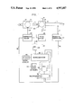
- FIG. 1 is a system block diagram of the preferred embodiment of the invention. illustrating the interactive relations among the major components.
- FIG. 2 is a block diagram of another embodiment of the gas delivery system. illustrating a variation in flow measurement.
- FIG. 3 shows typical performance characteristics of a drag compressor suitable for use in the system.
- FIG. 4 shows typical performance characteristics of a centrifugal compressor, illustrating drawbacks of this type.
- FIG. 5 is a sectional view of an enclosed, motor-driven drag compressor that can be used in the preferred embodiment.
- FIG. 6 is a front view of the rotor of the drag compressor shown in FIG. 5.
- FIG. 7 is a fragmented sectional side view of a drag compressor, showing the rotor and stator flow channels.
- FIG. 8 is a schematic diagram of the compressor speed control.
- FIG. 9 is a sectional view of a motor-driven directional valve that can be used the preferred embodiment.
- FIG. 10 is a schematic diagram of the actuation control for the directional valve shown in FIG. 9.
- FIG. 11 is an illustration of the invention adapted for ventilation of a lung, in the gas delivery condition.
- FIG. 12 is an illustration of the invention adapted for ventilation of a lung, shown in the exhaust condition.
- FIG. 13 is a schematic diagram of a closed loop oxygen control for ventilation lung.
- FIG. 15 is a schematic diagram of the invention adapted for alternate pneumatic driving of two receivers such as the ventricles of an artificial heart.
- FIG. 16 is a sectional view of a dual rotor drag compressor.
- FIG. 17 is a front view of the drag compressor shown in FIG. 16.
- the preferred gas delivery system includes a compressor 10, driven by a rotary electric motor 12, to supply pressurized gas to a pneumatic outlet -4 through an intermediate pneumatic line 15 and a directional valve 16 driven by an electrical actuator 18.
- the compressor motor is powered from a controllable electronic driver 20, through an electrical line 23, and the valve actuator is powered from a separate controllable electronic driver 22, through an electrical line 25.
- the compressor driver is controlled by a voltage from electrical line 24, obtained indirectly from a microcomputer 26 through a digital to analog converter (DAC) 28.
- Valve driver 22 is controlled by a signal obtained directly from the microcomputer through electrical line 3.
- Analog signals to the microcomputer are introduced through an analog input unit 32, which includes a multiplexer 34 and an analog to digital converter (ADC) 36.
- ADC analog to digital converter
- An analog voltage related to compressor speed is fed from compressor driver 20 to multiplexer 34 through line 38.
- a pressure transducer 40 senses pressure in pneumatic line 14 through pneumatic line 41 and supplies an analog voltage related to the line pressure to multiplexer 34 through electrical line 42.
- Functions and data are entered into the microcomputer through a keyboard 44, and data is shown on a digital display 46.
- the microcomputer can be one of several available, such as an HD63P01 single chip microcomputer, and it includes a microcomputer, a random access memory (RAM) and an erasable programmable read-only memory (EPROM).
- a typical DAC is the DAC0800LCN, and a typical multiplexed ADC is the ADC0809CCN.
- the compressor speed and the valve position are determined by the microcomputer, which controls the gas volume cyclically delivered to the line, the cyclic frequency (or rate), and the delivery time interval (or duty cycle).
- the compressor speed is also adjusted by the microcomputer to prevent the average gas pressure during a delivery interval from exceeding a pre-set limit.
- valve 10 is positioned to direct flow from line 16 to output line 14.
- valve 16 diverts the flow into pneumatic line 17.
- Line 19 is available to feed a controlled flow of a second gas through valve 16 into output line 14.
- Gas flow rate from the compressor is calibrated by the microcomputer from the pressure transducer signal and the compressor speed signal by entering these signals into the stored, calibrated compressor characteristic (speed, pressure, flow rate).
- Delivered gas volume is calculated by the microcomputer by integrating the flow rate. The calculated value is compared with the selected value of air volume and, if there is an error, the compressor speed is adjusted slowly by the microcomputer over several cycles, until the two values of air volume coincide. The compressor speed is similarly reduced if excessive gas pressure is sensed.
- the microcomputer also determines the average pressure and flow rate during the delivery interval and calculates the characteristic pneumatic line resistance from these values. The calculated pneumatic resistance is stored for setting initial conditions for intermittent use of the system.
- the pressure drop across the directional valve and associated flow passages is made very small, so that the pneumatic line pressure can be taken to be the same as the compressor outlet pressure within an acceptable error. For greatest accuracy, a correction can be made by the computer.
- the system of FIG. 1 is advantageous because of its simplicity, requiring a minimum number of active elements. It is particularly applicable with types of compressors having a wide dynamic range, and where the variation of flow rate with pressure at constant speed is reasonably uniform and not excessive. These requirements are characteristic of drag (or regenerative) compressors as well as positive displacement machines.
- Dynamic types such as centrifugal compressors, have a limited dynamic range due to surge (instability) at low flow rates, and the flow/pressure characteristic is less favorable for use in the inferential control system shown in FIG. 1.
- surge instability
- flow/pressure characteristic is less favorable for use in the inferential control system shown in FIG. 1.
- differential pressure sensor in the gas line can be objectionable, because it can reduce the pressure in the delivery line by an excessive amount, particularly where the range of delivered pressure is low.
- Linear pressure sensors with very low drops are available, but these are relatively large, and they require the use of very low pressure transducers, which are also relatively large, delicate and expensive, particularly for portable applications.
- a hot wire type of anemometer could be used to measure flow rate, such meters are undesirable for portable applications because of slow response, high energy drain and cost.
- FIG. 2 A microcomputerized gas delivery system which utilizes a pressure drop flowmeter for direct measurement of flow rate is shown in FIG. 2.
- linear flow sensor 48 is located in pneumatic line 14, and differential pressure transducer 50 senses the pressure drop across the flow sensor through pneumatic lines 52 and 54 and provides a proportional voltage through electrical line 56 to multiplexer 34.
- the flow sensor can be one of several low pressure drop linear flow sensors, such as a Hans Rudolph Model 4719 Pneumotach, and the differential pressure transducer can be one of several low pressure types, such as a Vacumed Celesco Model 603151-410.
- pressure transducer 40 senses both positive and negative gauge pressures. If the line pressure becomes lower than a preselected negative threshold, the control will cause the directional valve 16 to move to the delivery position.
- Table I lists the control functions for operation of the system of FIG. 1 adapted for applications as a volume cycled respirator for patients with impaired lung function.
- Table I lists the control functions for operation of the system of FIG. 1 adapted for applications as a volume cycled respirator for patients with impaired lung function.
- Table I A., selected values of tidal volume, respiration period, inspiration duty cycle, inspiration pressure limit and negative pressure threshold are entered into the computer memory by the keyboard. Ranges of measured values are given in Item B, equations for computed values are given in item C, and computer instructions are listed in Items D and E.
- the advantage of a regenerative drag compressor for use in the gas delivery system shown in FIG. 1 is illustrated in the performance characteristic of a suitable drag compressor, in FIG. 3.
- This is based on an endurance and calibration stability test for a drag compressor that is used in a model of a wearable respirator that has been successfully built and tested.
- the characteristic at constant speed not deviate greatly from a straight line.
- a variation in slope for a constant speed characteristic of 2 to 1 is acceptable.
- the horizontal bars on each constant speed characteristic are the maximum excursions of the values for an endurance test of over 2000 hours. The standard deviations are significantly less. This shows that the calibration is sufficiently stable for use in obtaining inferred flow rates without the need for excessively frequent calibrations.
- FIG. 4 The disadvantages of a centrifugal type of dynamic compressor for use in the gas delivery system shown in FIG. 1 are illustrated in the performance characteristic of a centrifugal compressor in FIG. 4. This is based on a design for a centrifugal compressor for the same function as the drag compressor whose performance is presented in FIG. 3. It is seen that at a high airway resistance, the characteristic at constant speed is almost horizontal. At low airway resistance it is almost vertical. The change in slope is over 40 to 1. In the horizontal region it would be very difficult to store sufficient pressure information to obtain reliable flow readings. In addition, a portion of the operating range is to the left of the surge line, where operation is unstable.
- FIG. 5 is a sectional view of a motor-driven drag compressor assembly that has been built and is being used in an engineering model of a wearable respirator. This is used because it has a reasonably steep and uniform characteristic (pressure vs. flow) which is favorable for good control performance for the system of FIG. 1; the construction is simple; and there are no contacting surfaces, providing high reliability and long life.
- FIG. 6 is a front view of rotor 58 clearly showing the vanes 62 which are oriented at an angle of 45 degrees to the axis.
- a side view of the impeller and stator showing the inlet and outlet are pictorially illustrated in FIG. 7.
- Air or gas enters through inlet port 68 and then is dragged by the impeller through the annular channel where it flows through an angle of approximately 340 degrees before it exits through the conical outlet diffuser 66.
- Inlet and the outlet are separated by a small block seal which has a very small clearance with the rotating vanes. Although this clearance is smaller than that required by centrifugal compressors, it is not as small or critical as that required for positive displacement types.
- brushless DC motor 60 has a multiplicity of phases which are delivered in sequence from the multi-phase motor drive 70. Pulses from a Hall effect commutating sensor in one of the phases are fed through line 72, capacitor 74, and line 76 to a frequency to analog converter 78. An analog voltage, proportional to motor speed, is fed through line 38 to analog input unit 32 to the microcomputer, where it is compared with the reference. A speed control voltage is fed from DAC 28 through line 24 and resistor 80 to pulse width modulator 82. The pulse width modulator enables motor drive control switch 84, to form a proportional switching period at a high frequency, typically 10 kHz. The control switch disables the motor drive, and the pulse width corresponds to the speed control voltage, thus varying the effective DC voltage applied to each motor phase an changing the speed of the motor.
- FIG. 9 is a detailed assembly drawing of a typical directional valve that can be used as valve 16 in the systems shown in FIG. 1 and FIG. 2.
- the valve assembly consists of a housing 84 containing a chamber 86 with an inlet port 88 for a first gas, typically air, another inlet port 90 for a supplementary second gas, typically oxygen an outlet port 92 for the gas mixture, and exhaust ports 94.
- a valve poppet 96 is driven by valve actuator 18, which consists of a DC gear motor 98 coupled to linear rack 100 which is fastened to poppet 96. In the position shown in FIG. 9, poppet 96 seals exhaust ports 94 through O-ring 102 and the first gas and the second gas are supplied and flow through port 92 into the outlet line 14.
- the motor drives rack 100 and poppet 06 into the opposite extreme position in which it seals port 90 through an O-ring 104.
- the inlet aperture 106 for port 90 has a relatively small diameter so as to reduce the pressure force of the second gas when aperture 106 is sealed, and to prevent that pressure force from causing poppet 96 to open and allow the second gas to leak into the outlet.
- poppet 96 uncovers ports 94 and allows the inlet gas flow to exhaust, diverting it from the outlet 92.
- the purpose of sealing aperture 106 in port 90 is to prevent loss of the second gas during the exhaust interval.
- valve when used in a respirator, it may be desired to add oxygen (second gas) to the compressed air (first gas) being applied to inflate the lung of the patient in the inspiration interval.
- first gas compressed air
- second gas compressed air
- first gas compressed air
- the poppet seals off the oxygen line as it opens the exhaust ports to prevent loss of oxygen into the exhaust.
- An exhausting type of directional valve is used to bypass output of the compressor to atmosphere, or another exhaust line, rather than to shut off the compressor supply, because for drag compressors (also positive displacement pumps) high pressures would be generated, and it would be necessary to vary the compressor speed, which would be difficult to accomplish in the time interval available, due to the inertia of the rotating parts
- FIG. 10 A schematic diagram of valve driver 22 for actuation of the directional valve 16 from the microcomputer is illustrated in FIG. 10.
- Line 30 from the microcomputer contains two conductors, Conductor 108, which applies a positive voltage to drive the valve motor in a clockwise direction to seat the poppet against the exhaust and deliver flow to output line 14, and Conductor 110, which applies a positive voltage to drive the valve motor in a counter-clockwise direction to open the exhaust and divert the flow from the compressor.
- FIG. 11 illustrates the use of such an expiration valve in the inspiration interval.
- Gas is delivered through directional valve 16 to line 14, then through a uni-directional valve 128, and through the central channel of the expiration valve 130.
- the exhaust port 132 of expiration valve 130 is shut off by pressurized diaphragm 134. Because of the unbalanced area on diaphragm 134, a relatively small pilot pressure is sufficient to actuate the diaphragm and close exhaust port 132. This pilot pressure is obtained from tap 136 in housing 84 of directional valve 16. It has been found that the normal line pressure drop between the directional and expiration valves during inspiration is sufficient to actuate the diaphragm 134 to close off exhaust port 132.
- exhaust port 132 During expiration, if uni-directional valve 126 were not inserted into the delivery line, exhaust port 132 would remain closed by the diaphragm 134, as the pressure drop with the expiration air passing through the valve exhaust ports 94 is not sufficient to lift the diaphragm, due to the unbalanced area. With the insertion of uni-directional valve 128 into the line, back flow of expired air through exhaust ports 94 in directional valve 16 is prevented, and the expiration pressure is then sufficient to lift the diaphragm and permit expired air to flow through exhaust port 132 at expiration valve 130. This condition is illustrated in FIG. 12. The second gas inlet port 90 is not shown in directional valve 16 for the sake of clarity.
- the concentration is selectable and controlled at the desired value.
- FIG. 13 is a schematic diagram of a closed-loop system for controlled delivery of oxygen.
- Oxygen is supplied from a container, such as a pressurized bottle 134, through a pressure regulator 136 and an electric motor-driven valve 140 to port 90 of directional valve 16, where it passes through aperture 106 and joins with air entering port 88 from the compressor.
- the gases flow through a mixing chamber 142 where they are thoroughly mixed by baffles 144, the mixture exiting into line 14.
- the oxygen concentration in the mixed gas is sensed by a galvanic oxygen sensor 146, an example of which is a Rexnord galvanic fuel cell type. This type of sensor generates an electrical analog signal proportional to sensed oxygen concentration.
- the oxygen signal is fed to the analog input unit 32, where it is converted to digital form and put into the microcomputer 26.
- the measured oxygen concentration is compared with the selected reference valve, and any error is converted in a dedicated DAC 148, and fed to an electronic driver 150 to actuate oxygen valve 140 until the error is nulled and the measured oxygen concentration equals the selected value.
- the purpose of mixing chamber 142 is to prevent false measurements due to concentration gradients.
- a closed loop oxygen control as shown in FIG. 13 was adapted to the new gas delivery system applied as a respirator, and it provided satisfactory performance.
- Drawbacks are in the size of the mixing chamber and the sensor, which add to the size of a miniature respirator, and to the limited shelf life of the sensor, which increases cost and maintenance, particularly if oxygen is not regularly required.
- Control valve 140 includes a position feedback device, such as a potentiometer, which provides a signal related to valve position by electrical lead 152 to the microcomputer through analog input unit 32.
- valve 140 It is not necessary to have a continuous automatic adjustment of valve 140 through the microcomputer. A normal valve could be used and adjusted manually to a calculated position. This procedure is less convenient, but it has the advantage that interconnection between the oxygen control and the computer control is not required. It should also be understood that a well-known differential pressure flow controller could be used in the oxygen line in place of pressure regulator 136 and valve 140.
- Another primary application for the new gas delivery system is as a driver for a pneumatic artificial ventricle.
- a pneumatically-driven artificial ventricle such as a Utah type, or Kantrowitz mechanical auxiliary ventricle (aortic patch), which will find use as implanted ventricular assist devices
- the system operates as shown in FIG. 1 or FIG. 2.
- the single ventricle system is schematically similar to the respirator application, the artificial ventricle replacing the lung as a compliant load, but the operating parameters, such as flow rates, pressures, cycle repetition rates, are much different.
- One different application is for driving a bi-ventricular total artificial heart.
- the compressor alternately inflates a right and then a left pneumatic ventricle.
- Another element that may be required for a pneumatic artificial ventricle that is not required by a lung is provision for some degree of suction to aid in filling the ventricle.
- FIG. 15 Application of the new gas delivery system for driving a bi-ventricular artificial heart as well as provision for applying suction are illustrated in FIG. 15.
- a compressor 154 delivers pressurized air through a pneumatic line 156 to a double-acting shuttle valve 158 which alternately directs air to the right ventricle through port 160 and to the left ventricle through port 162.
- the exhaust air passing from valve 158 through port 164 and then to atmosphere through pneumatic line 166 and suction control valve 168.
- the inlet air to compressor 154 is obtained from one or both of lines 164 and 166.
- a poppet type of valve is advantageous for use as a directional control with a total artificial heart (TAH) in which three positions are required: two positions in which one of the ventricles is pressurized and the other exhausts, and a center position in which both ventricles as well as the compressor exhaust to the outlet.
- TAH total artificial heart
- the right chamber 170 communicates with the left ventricle
- the central chamber 172 communicates either with the suction source or atmosphere.
- Double disk poppets in both the right and left chambers are connected to the driver motor 174 through a helical rack and gear combination 176.
- a position-sensing potentiometer 178 is used to control the center position of the shaft.
- disk 180 When the shaft is at an extreme left position, disk 180 seals off the left compressor port 181 and the right ventricle exhausts into central chamber 172 and out of the suction port 164. Disk 182 seals right chamber 170 from central chamber 172 and pressurized air from the compressor flows to the left ventricle.
- Disk 182 Seals right chamber 170 from central chamber 172 and pressurized air from the compressor flows to the left ventricle.
- the operation is reversed when the shaft is in its extreme right position, when disk 184 seals off the right compressor port 186 and disk 188 seals the left chamber 190 from central chamber 172.
- In the center position which is shown in the illustration, all ports are open, and they exhaust through suction port 164. No sliding seals are required, since the shaft bearings are incorporated in the same walls as the exhaust aperture, which could be kidney-shaped.
- One desirable feature of this arrangement is that the valve is approximately balanced.
- compressor pressure applies a force to the right on disk 180, and it applies a force to the left on disk 182.
- the only imbalance is due to the area of the drive shaft, and that of an O-ring, which can be made a very small fraction of the disk area.
- Transducer 192 measures the pressure or vacuum in chamber 190 and transducer 194 measures the pressure or vacuum in chamber 170.
- the transducer outputs are fed to a microcomputer based control 196, which incorporates elements 26, 28, 32, 44 and 46 shown in FIG. 1.
- Suction is applied to Port 164 by the inlet to compressor 154.
- the suction is adjusted by exhaust valve 168 which is positioned by a signal from microcomputer control 196 through exhaust valve driver 198 to maintain suction at programmed values.
- FIGS. 5 and 6 are suitable for a miniature respirator, a similar compressor to provide the higher power required by a pneumatic artificial ventricle must rotate at a much higher speed for the same rotor dimensions, which requires a special motor. It was found possible to achieve the desired power at a reduced speed by mounting two rotors on the same motor shaft, achieving a dual drag compressor in a single unit.
- vanes 200 in inner rotor 202 communicate with annular channel 204 in inner stator 206.
- Vanes 208 in outer rotor 210 communicate with annular channel 212 in outer stator 214.
- Both rotors are mounted on shaft extension 216, and they are rotated together by drive motor 218, which is sealed from the environment by housing 220 to avoid leakage.
- the inlet and outlet arrangements are illustrated in FIG. 17. Inlet 222 and outlet 224 lead to annular channel 204 in inner stator 206, and inlet 226 and outlet 228 lead to annular channel 212 in outer stator 214.
Abstract
Description
TABLE I ______________________________________ TYPICAL RESPIRATOR CONTROL FUNCTIONS ______________________________________A. Select 1.Tidal volume 200 to 1000ml 2.Respiration period 2 to 7.5 sec. 3.Inspiration duty cycle 20 to 33% (of resp.) period) 4. Inspiration pressure limit 30 to 70 cm H.sub.2 O 5. Negative pressure level for 0 to -20 cm H.sub.2 O patient-initiated inspiration 6. Nominal pneumatic airway resistance value 0.2 to 1.0 cm H.sub.2 O/1pm R.sub.a = P.sub.a /Q.sub.a)B. Measure 1. Compressor speed (N) 2,000 to 14,000rpm 2. Patient inspiration pressure (P.sub.i) -30 to +80 cm H O 3. Inspiration time interval (ΔT.sub.i) 0.3 to 3.0 sec. 4. Expiration time interval (ΔT.sub.e) 1.0 to 10.0sec. C. Compute 1. Inspiration flow rate Q.sub.ai = f(P.sub.i,N) 2. Inspiration air volume ##STR1## 3. Average inspiration pressure ##STR2## 4. Average inspiration flow rate Q.sub.ai = V.sub.ai /Δt.sub.i 5. Characteristic pneumatic airway R.sub.a = P.sub.ai /Q.sub.ai resistance 6. Respiratory cycle period Δt.sub.c = Δt.sub.i + Δt.sub.e D. During inspiration (delivery)interval 1. Read compressor speed and compressor outlet pressure (inspiration pressure). 2. Divide selected tidal volume by inspiration time to obtain reference flow rate for an inspiration interval. 3. Integrate instantaneous inspiration flow rate and divide by inspiration time to obtain average flow rate during an in- spiration interval. 4. Compare reference and measured average values of inspiration flow rate to obtain a difference for the inspiration interval. 5. Adjust the compressor speed in the next succeeding inspiration interval by an amount related to the flow rate difference and in a direction to reduce the difference. 6. Repeat Step 5 until the difference is at a minimum. 7. Compare measured pneumatic airway resistance with nominal selected pneumatic resistance and correct reference value. Store measured resistance value for future reference and display. 8. Compare measured average value of compressor outlet pressure (inspiration pressure) with selected value of pressure limit. 9. If measured pressure exceeds selected limit, reduce compressor speed in successive inspiration intervals, until measured pressure is less than selected limit, and actuate alarm. E. During expiration (exhaust) interval: 1. If measured pressure after expiration becomes more negative than selected threshold of negative pressure for patient initiated inspiration, actuate selector valve to inspiration position. 2. If actual expiration time is less than selected expiration time, reduce respiratory cycle period by increment related to difference between actual and selected expiration time intervals. ______________________________________
Claims (17)
Priority Applications (5)
| Application Number | Priority Date | Filing Date | Title |
|---|---|---|---|
| US07/192,177 US4957107A (en) | 1988-05-10 | 1988-05-10 | Gas delivery means |
| EP89907414A EP0419551B1 (en) | 1988-05-10 | 1989-05-08 | Gas delivery means |
| JP1507102A JP2809459B2 (en) | 1988-05-10 | 1989-05-08 | Gas delivery means |
| DE68918941T DE68918941T2 (en) | 1988-05-10 | 1989-05-08 | GAS SUPPLY MEANS. |
| PCT/US1989/001961 WO1989010768A1 (en) | 1988-05-10 | 1989-05-08 | Gas delivery means |
Applications Claiming Priority (1)
| Application Number | Priority Date | Filing Date | Title |
|---|---|---|---|
| US07/192,177 US4957107A (en) | 1988-05-10 | 1988-05-10 | Gas delivery means |
Publications (1)
| Publication Number | Publication Date |
|---|---|
| US4957107A true US4957107A (en) | 1990-09-18 |
Family
ID=22708579
Family Applications (1)
| Application Number | Title | Priority Date | Filing Date |
|---|---|---|---|
| US07/192,177 Expired - Fee Related US4957107A (en) | 1988-05-10 | 1988-05-10 | Gas delivery means |
Country Status (5)
| Country | Link |
|---|---|
| US (1) | US4957107A (en) |
| EP (1) | EP0419551B1 (en) |
| JP (1) | JP2809459B2 (en) |
| DE (1) | DE68918941T2 (en) |
| WO (1) | WO1989010768A1 (en) |
Cited By (175)
| Publication number | Priority date | Publication date | Assignee | Title |
|---|---|---|---|---|
| US5107830A (en) * | 1987-02-21 | 1992-04-28 | University Of Manitoba | Lung ventilator device |
| EP0483556A1 (en) * | 1990-10-31 | 1992-05-06 | Siemens-Elema AB | Ventilator |
| US5117819A (en) * | 1990-09-10 | 1992-06-02 | Healthdyne, Inc. | Nasal positive pressure device |
| FR2675050A1 (en) * | 1991-04-12 | 1992-10-16 | Draegerwerk Ag | METHOD FOR CALIBRATING A FLOW SENSOR IN A RESPIRATORY SYSTEM. |
| US5183037A (en) * | 1988-08-17 | 1993-02-02 | Neotronics Medical Limited | Resuscitator valve |
| US5231981A (en) * | 1991-03-20 | 1993-08-03 | N.A.D., Inc. | Display panel with pistol grip for use with anesthesia apparatus |
| US5271388A (en) * | 1989-06-07 | 1993-12-21 | Caduceus Limited | Medical ventilator |
| US5307795A (en) * | 1989-06-07 | 1994-05-03 | Caduceus Limited | Medical ventilators |
| US5313937A (en) * | 1989-09-22 | 1994-05-24 | Respironics Inc. | Leak compensation method and apparatus for a breathing system |
| US5353788A (en) * | 1992-09-21 | 1994-10-11 | Miles Laughton E | Cardio-respiratory control and monitoring system for determining CPAP pressure for apnea treatment |
| US5398676A (en) * | 1993-09-30 | 1995-03-21 | Press; Roman J. | Portable emergency respirator |
| US5452714A (en) * | 1990-06-07 | 1995-09-26 | Infrasonics, Inc. | Human lung ventilator system |
| US5456264A (en) * | 1994-03-31 | 1995-10-10 | Universite Laval | Accuracy of breath-by-breath analysis of flow volume loop in identifying flow-limited breathing cycles in patients |
| US5490502A (en) * | 1992-05-07 | 1996-02-13 | New York University | Method and apparatus for optimizing the continuous positive airway pressure for treating obstructive sleep apnea |
| US5509406A (en) * | 1994-07-20 | 1996-04-23 | Siemens Elema Ab | Anesthesia device |
| WO1996011717A1 (en) | 1994-10-14 | 1996-04-25 | Bird Products Corporation | Portable drag compressor powered mechanical ventilator |
| US5549139A (en) * | 1989-10-27 | 1996-08-27 | Storz Instrument Company | Pneumatic controls for ophthalmic surgical system |
| US5575283A (en) * | 1994-02-14 | 1996-11-19 | Siemens-Elema Ab | Device for determining an opening pressure in the lungs |
| US5598838A (en) * | 1995-04-07 | 1997-02-04 | Healthdyne Technologies, Inc. | Pressure support ventilatory assist system |
| WO1997010019A1 (en) * | 1995-09-15 | 1997-03-20 | Resmed Limited | Flow estimation and compensation of flow-induced pressure swings in cpap treatment and assisted respiration |
| US5632269A (en) * | 1989-09-22 | 1997-05-27 | Respironics Inc. | Breathing gas delivery method and apparatus |
| US5647351A (en) * | 1994-09-10 | 1997-07-15 | Dragerwerk Ag | Ventilating system for supplying a patient with respiratory gas and method for triggering the respiratory phases in said system |
| US5647346A (en) * | 1994-10-08 | 1997-07-15 | Dragerwerk Ag | Medical apparatus having a metering device |
| US5673689A (en) * | 1995-02-09 | 1997-10-07 | Puritan Bennett Corporation | Piston based ventilator |
| US5678539A (en) * | 1995-01-11 | 1997-10-21 | Dragerwerk Aktiengesellschaft | Respirator with an input and output unit |
| US5797393A (en) * | 1995-05-05 | 1998-08-25 | Dragerwerk Aktiengesellschaft | Method for controlling the respirating phase in a ventilating apparatus |
| US5865174A (en) * | 1996-10-29 | 1999-02-02 | The Scott Fetzer Company | Supplemental oxygen delivery apparatus and method |
| US5876359A (en) * | 1994-11-14 | 1999-03-02 | Bock; Malcolm G. | Sequential compression device controller |
| WO1999013932A1 (en) * | 1997-09-19 | 1999-03-25 | Respironics, Inc. | Medical ventilator |
| US5923106A (en) * | 1998-06-26 | 1999-07-13 | Isaak; Mark Frank | Integrated fuel cell electric motor with static fuel cell and rotating magnets |
| US6006748A (en) * | 1996-10-16 | 1999-12-28 | Resmed Limited | Vent valve apparatus |
| USD421298S (en) * | 1998-04-23 | 2000-02-29 | Resmed Limited | Flow generator |
| US6029660A (en) | 1996-12-12 | 2000-02-29 | Resmed Limited | Substance delivery apparatus |
| US6029665A (en) * | 1993-11-05 | 2000-02-29 | Resmed Limited | Determination of patency of airway |
| EP0987614A1 (en) * | 1996-08-15 | 2000-03-22 | Nellcor Puritan Bennett Incorporated | Apparatus and method for controlling output of an oxygen concentrator |
| US6041780A (en) * | 1995-06-07 | 2000-03-28 | Richard; Ron F. | Pressure control for constant minute volume |
| WO2000024447A1 (en) | 1998-10-23 | 2000-05-04 | Pulmonetic Systems, Inc. | Ventilator system |
| US6091973A (en) * | 1995-04-11 | 2000-07-18 | Resmed Limited | Monitoring the occurrence of apneic and hypopneic arousals |
| US6095138A (en) * | 1997-05-16 | 2000-08-01 | Siemens Elema Ab | Portable respiration apparatus, and system employing same |
| WO2000045883A1 (en) * | 1999-02-04 | 2000-08-10 | Versamed Medical Systems Ltd. | Computer-controlled portable ventilator |
| US6105575A (en) * | 1994-06-03 | 2000-08-22 | Respironics, Inc. | Method and apparatus for providing positive airway pressure to a patient |
| US6119723A (en) | 1997-02-14 | 2000-09-19 | Resmed Limited, | Apparatus for varying the flow area of a conduit |
| US6123082A (en) * | 1996-12-18 | 2000-09-26 | Resmed Limited | Device for preventing or reducing the passage of air through the mouth |
| US6135967A (en) | 1999-04-26 | 2000-10-24 | Fiorenza; Anthony Joseph | Respiratory ventilator with automatic flow calibration |
| US6142150A (en) * | 1998-03-24 | 2000-11-07 | Nellcor Puritan-Bennett | Compliance compensation in volume control ventilator |
| US6152129A (en) * | 1996-08-14 | 2000-11-28 | Resmed Limited | Determination of leak and respiratory airflow |
| US6155986A (en) * | 1995-06-08 | 2000-12-05 | Resmed Limited | Monitoring of oro-nasal respiration |
| US6182657B1 (en) * | 1995-09-18 | 2001-02-06 | Resmed Limited | Pressure control in CPAP treatment or assisted respiration |
| US6213119B1 (en) * | 1995-10-23 | 2001-04-10 | Resmed Limited | Inspiratory duration in CPAP or assisted respiration treatment |
| US6216691B1 (en) | 1997-11-03 | 2001-04-17 | Resmed Limited | Mounting body |
| WO2001026721A1 (en) * | 1999-10-14 | 2001-04-19 | The Trustees Of Boston University | Variable peak pressure ventilation method and system |
| US6237593B1 (en) | 1993-12-03 | 2001-05-29 | Resmed Limited | Estimation of flow and detection of breathing CPAP treatment |
| US6237592B1 (en) * | 1995-07-03 | 2001-05-29 | Resmed Limited | Auto-calibration of pressure transducer offset |
| US6240919B1 (en) | 1999-06-07 | 2001-06-05 | Macdonald John J. | Method for providing respiratory airway support pressure |
| US6240921B1 (en) | 1993-12-01 | 2001-06-05 | Resmed, Ltd. | Automated stop/start control in the administration of CPAP treatment |
| WO2000018347A3 (en) * | 1998-09-30 | 2001-06-21 | Respironics Inc | Interactive pressure support system and method |
| US6253764B1 (en) | 1996-05-08 | 2001-07-03 | Resmed, Ltd. | Control of delivery pressure in CPAP treatment or assisted respiration |
| DE19755951C2 (en) * | 1997-06-11 | 2001-07-26 | Mitsubishi Electric Corp | Fuel injection device for direct injection |
| US6321748B1 (en) * | 1998-03-10 | 2001-11-27 | Nellcor Puritan Bennett | Closed loop control in a piston ventilator |
| US6336454B1 (en) | 1997-05-16 | 2002-01-08 | Resmed Limited | Nasal ventilation as a treatment for stroke |
| EP1175239A1 (en) * | 1999-05-06 | 2002-01-30 | Resmed Limited | Control of supplied pressure in assisted ventilation |
| US6367474B1 (en) * | 1997-11-07 | 2002-04-09 | Resmed Limited | Administration of CPAP treatment pressure in presence of APNEA |
| FR2816049A1 (en) * | 2000-10-31 | 2002-05-03 | Taema | METHOD AND DEVICE FOR MEASURING THE FLOW OF A GAS UNDER PRESSURE DELIVERED BY A TURBINE |
| US6390091B1 (en) * | 1999-02-03 | 2002-05-21 | University Of Florida | Method and apparatus for controlling a medical ventilator |
| US6397841B1 (en) | 1997-06-18 | 2002-06-04 | Resmed Limited | Apparatus for supplying breathable gas |
| US6422237B1 (en) * | 1999-05-18 | 2002-07-23 | DRäGER MEDIZINTECHNIK GMBH | Respirator with a breathing circuit |
| US20020124848A1 (en) * | 1987-06-26 | 2002-09-12 | Sullivan Colin Edward | Method and apparatus useful in the diagnosis of obstructive sleep apnea of a patient |
| US6484719B1 (en) * | 1996-09-23 | 2002-11-26 | Resmed, Inc. | Method for providing ventilatory assistance in a spontaneously breathing subject |
| US20020185127A1 (en) * | 1995-08-17 | 2002-12-12 | Melker Richard J. | Hybrid microprocessor controlled ventilator unit |
| US20030005932A1 (en) * | 2001-07-04 | 2003-01-09 | Siemens Eleama Ab | Fluid flow regulation system |
| US6536432B2 (en) * | 1998-11-25 | 2003-03-25 | Respironics, Inc. | Pressure support system with a low leak alarm and method of using same |
| US6571796B2 (en) | 2001-02-08 | 2003-06-03 | University Of Florida | Tracheal pressure ventilation respiratory system |
| US20030121519A1 (en) * | 1994-06-03 | 2003-07-03 | Estes Mark C. | Method and apparatus for providing positive airway pressure to a patient |
| US20030159697A1 (en) * | 2002-02-22 | 2003-08-28 | Allan Wallace | Flow sensing apparatus |
| US6615831B1 (en) | 1999-07-02 | 2003-09-09 | Respironics, Inc. | Pressure support system and method and a pressure control valve for use in such system and method |
| US6635021B1 (en) | 1987-06-26 | 2003-10-21 | Resmed Limited | Method and apparatus useful in the diagnosis of obstructive sleep apnea of a patient |
| US6647983B2 (en) | 2000-03-17 | 2003-11-18 | The Johns Hopkins University | Low-pressure valve |
| US6651657B1 (en) * | 1999-12-18 | 2003-11-25 | DRäGER MEDIZINTECHNIK GMBH | Respirator for different forms of respiration |
| US20040003814A1 (en) * | 2000-08-17 | 2004-01-08 | Banner Michael J. | Endotracheal tube pressure monitoring system and method of controlling same |
| US20040071552A1 (en) * | 2000-06-19 | 2004-04-15 | Respironics, Inc. | Impeller and a pressure support system and method using such a method |
| US6739336B1 (en) * | 1999-09-24 | 2004-05-25 | Maquet Critical Care Ab | Arrangement and method for feedback control of a gas flow in a breathing assist apparatus |
| US20040103895A1 (en) * | 1997-10-01 | 2004-06-03 | Invacare Corporation | Oxygen conserving device utilizing a radial multi-stage compressor for high-pressure mobile storage |
| US6820618B2 (en) | 1999-02-03 | 2004-11-23 | University Of Florida Research Foundation, Incorporated | Method and apparatus for nullifying the imposed work of breathing |
| US20050005937A1 (en) * | 2003-06-20 | 2005-01-13 | Farrugia Steven Paul | Method and apparatus for improving the comfort of CPAP |
| US20050051168A1 (en) * | 2003-08-04 | 2005-03-10 | Devries Douglas F. | Portable ventilator system |
| US20050081855A1 (en) * | 1999-09-15 | 2005-04-21 | Michael Berthon-Jones | Patient-ventilator synchronization using dual phase sensors |
| US6895963B1 (en) * | 1999-06-16 | 2005-05-24 | Resmed Limited | Apparatus with automatic respiration monitoring and display |
| US20050112013A1 (en) * | 2003-08-04 | 2005-05-26 | Pulmonetic Systems, Inc. | Method and apparatus for reducing noise in a roots-type blower |
| US20060027234A1 (en) * | 2004-08-06 | 2006-02-09 | Gradon Lewis G | Autotitrating method and apparatus |
| US20060102180A1 (en) * | 1999-09-15 | 2006-05-18 | Michael Berthon-Jones | Patient-ventilator synchronization using dual phase sensors |
| US20060130835A1 (en) * | 2003-09-03 | 2006-06-22 | Ric Investments, Llc | Pressure support system and method |
| US20060225737A1 (en) * | 2005-04-12 | 2006-10-12 | Mr. Mario Iobbi | Device and method for automatically regulating supplemental oxygen flow-rate |
| US20060231097A1 (en) * | 2005-04-02 | 2006-10-19 | Dougherty Timothy R | Apparatus for CPAP therapy |
| US20060249153A1 (en) * | 2003-08-04 | 2006-11-09 | Pulmonetic Systems, Inc. | Mechanical ventilation system utilizing bias valve |
| US20070065301A1 (en) * | 2005-09-21 | 2007-03-22 | Gerold Goertzen | System and method for providing oxygen |
| US7204249B1 (en) * | 1997-10-01 | 2007-04-17 | Invcare Corporation | Oxygen conserving device utilizing a radial multi-stage compressor for high-pressure mobile storage |
| US20070221221A1 (en) * | 2006-02-23 | 2007-09-27 | Cooke Richard H | Ventilator for Rapid Response to Respiratory Disease Conditions |
| US7302950B2 (en) | 1991-12-20 | 2007-12-04 | Resmed Limited | Patient interface for respiratory apparatus |
| US7320320B2 (en) | 1993-11-05 | 2008-01-22 | Resmed Limited | Determination of patency of the airway |
| US20080196724A1 (en) * | 1999-02-12 | 2008-08-21 | Hossein Nadjafizadeh | Gas Supply Device for Sleep Apnea |
| WO2008102216A1 (en) * | 2007-02-20 | 2008-08-28 | Resmed Paris | Gas supply unit for a respiratory system |
| US20080216833A1 (en) * | 2007-03-07 | 2008-09-11 | Pujol J Raymond | Flow Sensing for Gas Delivery to a Patient |
| US20090090363A1 (en) * | 2007-10-05 | 2009-04-09 | Niland William F | Hyperthermic humidification system |
| US7527053B2 (en) | 2003-08-04 | 2009-05-05 | Cardinal Health 203, Inc. | Method and apparatus for attenuating compressor noise |
| US20090165795A1 (en) * | 2007-12-31 | 2009-07-02 | Nellcor Puritan Bennett Llc | Method and apparatus for respiratory therapy |
| US20090227887A1 (en) * | 2008-03-04 | 2009-09-10 | Howard C Peter | Metabolic analyzer transducer |
| US20090241953A1 (en) * | 2008-03-31 | 2009-10-01 | Nellcor Puritan Bennett Llc | Ventilator with piston-cylinder and buffer volume |
| US7607437B2 (en) | 2003-08-04 | 2009-10-27 | Cardinal Health 203, Inc. | Compressor control system and method for a portable ventilator |
| US20090270981A1 (en) * | 2008-04-23 | 2009-10-29 | Syncardia Systems, Inc. | Apparatus and method for pneumatically driving an implantable medical device |
| US20090301488A1 (en) * | 2005-11-23 | 2009-12-10 | Jianguo Sun | Method And Apparatus For Providing Positive Airway Pressure To A Patient |
| US20100024820A1 (en) * | 1994-09-12 | 2010-02-04 | Guy Bourdon | Pressure-Controlled Breathing Aid |
| US20100051026A1 (en) * | 2008-09-04 | 2010-03-04 | Nellcor Puritan Bennett Llc | Ventilator With Controlled Purge Function |
| US20100065054A1 (en) * | 2008-07-02 | 2010-03-18 | Bowman Bruce R | Methods for battery power management of positive airway pressure apparatus |
| US20100306992A1 (en) * | 2006-02-23 | 2010-12-09 | Richard Henry Cooke | Ventilator for Rapid Response to Respiratory Disease Conditions |
| US20110023879A1 (en) * | 2008-03-31 | 2011-02-03 | Nellcor Puritan Bennett Llc | Ventilator Based On A Fluid Equivalent Of The "Digital To Analog Voltage" Concept |
| US7997885B2 (en) | 2007-12-03 | 2011-08-16 | Carefusion 303, Inc. | Roots-type blower reduced acoustic signature method and apparatus |
| US20120001762A1 (en) * | 2007-08-06 | 2012-01-05 | Smith & Nephew Plc | Determining flow rate |
| USD653749S1 (en) | 2010-04-27 | 2012-02-07 | Nellcor Puritan Bennett Llc | Exhalation module filter body |
| USD655405S1 (en) | 2010-04-27 | 2012-03-06 | Nellcor Puritan Bennett Llc | Filter and valve body for an exhalation module |
| USD655809S1 (en) | 2010-04-27 | 2012-03-13 | Nellcor Puritan Bennett Llc | Valve body with integral flow meter for an exhalation module |
| US8156937B2 (en) | 2003-08-04 | 2012-04-17 | Carefusion 203, Inc. | Portable ventilator system |
| USRE43398E1 (en) | 1997-06-16 | 2012-05-22 | Respironics, Inc. | Methods and apparatus to generate liquid ambulatory oxygen from an oxygen concentrator |
| US8302602B2 (en) | 2008-09-30 | 2012-11-06 | Nellcor Puritan Bennett Llc | Breathing assistance system with multiple pressure sensors |
| US8434479B2 (en) | 2009-02-27 | 2013-05-07 | Covidien Lp | Flow rate compensation for transient thermal response of hot-wire anemometers |
| US8439037B2 (en) | 2009-12-01 | 2013-05-14 | Covidien Lp | Exhalation valve assembly with integrated filter and flow sensor |
| US8439036B2 (en) | 2009-12-01 | 2013-05-14 | Covidien Lp | Exhalation valve assembly with integral flow sensor |
| US8457706B2 (en) | 2008-05-16 | 2013-06-04 | Covidien Lp | Estimation of a physiological parameter using a neural network |
| US8469030B2 (en) | 2009-12-01 | 2013-06-25 | Covidien Lp | Exhalation valve assembly with selectable contagious/non-contagious latch |
| US8469031B2 (en) | 2009-12-01 | 2013-06-25 | Covidien Lp | Exhalation valve assembly with integrated filter |
| USD692556S1 (en) | 2013-03-08 | 2013-10-29 | Covidien Lp | Expiratory filter body of an exhalation module |
| USD693001S1 (en) | 2013-03-08 | 2013-11-05 | Covidien Lp | Neonate expiratory filter assembly of an exhalation module |
| US8596992B2 (en) | 2006-08-18 | 2013-12-03 | L•VAD Technology, Inc. | Air supply mechanism for ventricular assist system |
| US8631791B2 (en) | 2006-04-10 | 2014-01-21 | Somnetics Global Pte. Ltd. | Apparatus and methods for administration of positive airway pressure therapies |
| WO2014035461A1 (en) * | 2012-08-31 | 2014-03-06 | Electromed, Inc. | Air pulsator control system |
| USD701601S1 (en) | 2013-03-08 | 2014-03-25 | Covidien Lp | Condensate vial of an exhalation module |
| US8770199B2 (en) | 2012-12-04 | 2014-07-08 | Ino Therapeutics Llc | Cannula for minimizing dilution of dosing during nitric oxide delivery |
| US20140199605A1 (en) * | 2013-01-15 | 2014-07-17 | GM Global Technology Operations LLC | Transient Inlet Relative Humidity Estimation Via Adaptive Cathode Humidification Unit Model And High Frequency Resistance |
| US8800557B2 (en) | 2003-07-29 | 2014-08-12 | Covidien Lp | System and process for supplying respiratory gas under pressure or volumetrically |
| US8844537B1 (en) | 2010-10-13 | 2014-09-30 | Michael T. Abramson | System and method for alleviating sleep apnea |
| US8888711B2 (en) | 2008-04-08 | 2014-11-18 | Carefusion 203, Inc. | Flow sensor |
| USD731048S1 (en) | 2013-03-08 | 2015-06-02 | Covidien Lp | EVQ diaphragm of an exhalation module |
| USD731065S1 (en) | 2013-03-08 | 2015-06-02 | Covidien Lp | EVQ pressure sensor filter of an exhalation module |
| USD731049S1 (en) | 2013-03-05 | 2015-06-02 | Covidien Lp | EVQ housing of an exhalation module |
| USD734854S1 (en) * | 2013-09-09 | 2015-07-21 | Beaconmedaes Llc | Medical gas manifold |
| USD736905S1 (en) | 2013-03-08 | 2015-08-18 | Covidien Lp | Exhalation module EVQ housing |
| CN104874085A (en) * | 2014-02-28 | 2015-09-02 | 北京谊安医疗系统股份有限公司 | Self-test method of oxygen electromagnetic valve set for respirators and respirator |
| US9144658B2 (en) | 2012-04-30 | 2015-09-29 | Covidien Lp | Minimizing imposed expiratory resistance of mechanical ventilator by optimizing exhalation valve control |
| US20150292531A1 (en) * | 2004-04-08 | 2015-10-15 | RPM Industries, LLC | Methods and systems for performing, monitoring and analyzing multiple machine fluid processes |
| US20150328427A1 (en) * | 2012-12-26 | 2015-11-19 | Beijing Aeonmed Co., Ltd. | Pulse-width modulation method for controlling oxygen concentration in anesthetic machine or ventilator |
| USD744095S1 (en) | 2013-03-08 | 2015-11-24 | Covidien Lp | Exhalation module EVQ internal flow sensor |
| US20160138838A1 (en) * | 2014-11-14 | 2016-05-19 | Kaeser Kompressoren Se | Intercooler bypass |
| US9364624B2 (en) | 2011-12-07 | 2016-06-14 | Covidien Lp | Methods and systems for adaptive base flow |
| US9498589B2 (en) | 2011-12-31 | 2016-11-22 | Covidien Lp | Methods and systems for adaptive base flow and leak compensation |
| USD775345S1 (en) | 2015-04-10 | 2016-12-27 | Covidien Lp | Ventilator console |
| US9624918B2 (en) | 2012-02-03 | 2017-04-18 | Invacare Corporation | Pumping device |
| US9629971B2 (en) | 2011-04-29 | 2017-04-25 | Covidien Lp | Methods and systems for exhalation control and trajectory optimization |
| US9795756B2 (en) | 2012-12-04 | 2017-10-24 | Mallinckrodt Hospital Products IP Limited | Cannula for minimizing dilution of dosing during nitric oxide delivery |
| US9950135B2 (en) | 2013-03-15 | 2018-04-24 | Covidien Lp | Maintaining an exhalation valve sensor assembly |
| US10328187B2 (en) | 2007-07-02 | 2019-06-25 | Smith & Nephew Plc | Systems and methods for controlling operation of negative pressure wound therapy apparatus |
| US10398871B2 (en) | 2015-03-31 | 2019-09-03 | Vapotherm, Inc. | Systems and methods for patient-proximate vapor transfer for respiratory therapy |
| US10617801B2 (en) | 2007-08-06 | 2020-04-14 | Smith & Nephew Plc | Canister status determination |
| US10874817B1 (en) | 2018-12-05 | 2020-12-29 | Aires Medical LLC | Pulsed pressure swing adsorption system and method |
| US10918822B2 (en) | 2007-07-18 | 2021-02-16 | Vapotherm, Inc. | Humidifier for breathing gas heating and humidification system |
| US11077267B2 (en) | 2010-12-21 | 2021-08-03 | Fisher & Paykel Healthcare Limited | Pressure adjustment method for CPAP machine |
| US11103667B2 (en) | 2009-04-02 | 2021-08-31 | Breathe Technologies, Inc. | Methods, systems and devices for non-invasive ventilation with gas delivery nozzles in free space |
| US11123505B2 (en) | 2018-12-05 | 2021-09-21 | Aires Medical LLC | Breathing apparatus with breath detection software |
| US11135392B2 (en) | 2018-12-05 | 2021-10-05 | Aires Medical LLC | Mechanical ventilator |
| US11154672B2 (en) | 2009-09-03 | 2021-10-26 | Breathe Technologies, Inc. | Methods, systems and devices for non-invasive ventilation including a non-sealing ventilation interface with an entrainment port and/or pressure feature |
| US11229763B2 (en) | 2018-12-05 | 2022-01-25 | Aires Medical LLC | Mechanical ventilator with oxygen concentrator |
| US11351330B2 (en) | 2016-10-14 | 2022-06-07 | Vapotherm, Inc. | Systems and methods for high velocity nasal insufflation |
| US11359733B2 (en) * | 2018-12-05 | 2022-06-14 | Beech Health, Inc. | Check valve |
| US11400250B2 (en) | 2018-12-05 | 2022-08-02 | Aires Medical LLC | Mechanical ventilator with non-invasive option |
| US11497870B2 (en) | 2015-02-24 | 2022-11-15 | Somnetics International, Inc. | Systems and methods for estimating flow in positive airway pressure therapy |
| DE102022002797A1 (en) | 2022-08-02 | 2024-02-08 | Rajan Govinda | Dosing device for adding at least one pharmaceutically active substance to a breathing gas provided extracorporeally, device for providing a breathing gas with such a dosing device and method |
| US11896767B2 (en) | 2020-03-20 | 2024-02-13 | Covidien Lp | Model-driven system integration in medical ventilators |
Families Citing this family (32)
| Publication number | Priority date | Publication date | Assignee | Title |
|---|---|---|---|---|
| US5134995A (en) * | 1989-05-19 | 1992-08-04 | Puritan-Bennett Corporation | Inspiratory airway pressure system with admittance determining apparatus and method |
| US5259373A (en) * | 1989-05-19 | 1993-11-09 | Puritan-Bennett Corporation | Inspiratory airway pressure system controlled by the detection and analysis of patient airway sounds |
| FR2674133B1 (en) * | 1991-03-21 | 1993-06-11 | Taema | RESPIRATORY GAS PRESSURE SUPPLY SYSTEM AND METHOD FOR CONTROLLING SUCH A SYSTEM. |
| US5203343A (en) * | 1991-06-14 | 1993-04-20 | Board Of Regents, The University Of Texas System | Method and apparatus for controlling sleep disorder breathing |
| US6085747A (en) * | 1991-06-14 | 2000-07-11 | Respironics, Inc. | Method and apparatus for controlling sleep disorder breathing |
| US5458137A (en) * | 1991-06-14 | 1995-10-17 | Respironics, Inc. | Method and apparatus for controlling sleep disorder breathing |
| US5271389A (en) * | 1992-02-12 | 1993-12-21 | Puritan-Bennett Corporation | Ventilator control system that generates, measures, compares, and corrects flow rates |
| US5803066A (en) * | 1992-05-07 | 1998-09-08 | New York University | Method and apparatus for optimizing the continuous positive airway pressure for treating obstructive sleep apnea |
| US5645054A (en) * | 1992-06-01 | 1997-07-08 | Sleepnet Corp. | Device and method for the treatment of sleep apnea syndrome |
| FR2692152B1 (en) * | 1992-06-15 | 1997-06-27 | Pierre Medical Sa | BREATHING AID, PARTICULARLY FOR TREATING SLEEP APNEA. |
| FR2694697B1 (en) * | 1992-08-12 | 1994-10-14 | Sefam | Respiratory assistance device. |
| FR2695320B1 (en) * | 1992-09-04 | 1994-12-09 | Sefam | Method for regulating the pressure of an air flow and respiratory assistance device implementing said method. |
| CA2109017A1 (en) * | 1992-12-16 | 1994-06-17 | Donald M. Smith | Method and apparatus for the intermittent delivery of oxygen therapy to a person |
| FR2714837B1 (en) * | 1994-01-12 | 1996-09-06 | Saime | Device for assisting the ventilation of a patient, comprising in particular a volumetric inspiratory assistance mode. |
| ATE178498T1 (en) * | 1994-01-12 | 1999-04-15 | Saime Sarl | VENTILATORY USING A LOW PRESSURE RESPIRATORY SUPPORT METHOD |
| DE69533874T2 (en) * | 1994-08-01 | 2005-12-29 | Safety Equipment Sweden Ab | VENTILATOR |
| FR2724322A1 (en) * | 1994-09-12 | 1996-03-15 | Pierre Medical Sa | PRESSURE CONTROLLED BREATHING AID |
| IL114964A (en) * | 1995-08-16 | 2000-10-31 | Versamed Medical Systems Ltd | Computer controlled portable ventilator |
| DE19626924C2 (en) * | 1996-07-04 | 1999-08-19 | Epazon B V | Breathing gas supply device |
| US5701883A (en) * | 1996-09-03 | 1997-12-30 | Respironics, Inc. | Oxygen mixing in a blower-based ventilator |
| US6206652B1 (en) | 1998-08-25 | 2001-03-27 | Copeland Corporation | Compressor capacity modulation |
| FR2808207B1 (en) * | 2000-04-28 | 2003-03-21 | Hemocare | DEVICE FOR CONTROLLING RESPIRATORY ASSISTANCE APPARATUS AND CONTROL SYSTEM COMPRISING SUCH A DEVICE |
| DE10237973A1 (en) * | 2002-08-20 | 2004-03-04 | Gottlieb Weinmann Geräte für Medizin und Arbeitsschutz GmbH & Co. | Method and device for detecting a flow volume |
| US7282032B2 (en) | 2003-06-03 | 2007-10-16 | Miller Thomas P | Portable respiratory diagnostic device |
| JP2007501072A (en) * | 2003-08-04 | 2007-01-25 | パルモネティック システムズ インコーポレイテッド | Compressor control system for portable ventilators |
| US7487773B2 (en) | 2004-09-24 | 2009-02-10 | Nellcor Puritan Bennett Llc | Gas flow control method in a blower based ventilation system |
| US7788963B2 (en) * | 2006-10-31 | 2010-09-07 | Ric Investments, Llc | System and method for calibrating a determination of partial pressure of one or more gaseous analytes |
| US8157538B2 (en) | 2007-07-23 | 2012-04-17 | Emerson Climate Technologies, Inc. | Capacity modulation system for compressor and method |
| MX2011007293A (en) | 2009-01-27 | 2011-09-01 | Emerson Climate Technologies | Unloader system and method for a compressor. |
| US10378533B2 (en) | 2011-12-06 | 2019-08-13 | Bitzer Us, Inc. | Control for compressor unloading system |
| DE102015000175B3 (en) | 2015-01-02 | 2016-07-07 | Drägerwerk AG & Co. KGaA | Narkosemitteldosierer |
| CN116382221B (en) * | 2023-05-30 | 2023-08-11 | 深圳市亚能电力技术有限公司 | Conveying control method, conveying control device and conveying system |
Citations (17)
| Publication number | Priority date | Publication date | Assignee | Title |
|---|---|---|---|---|
| US3741208A (en) * | 1971-02-23 | 1973-06-26 | B Jonsson | Lung ventilator |
| US3768468A (en) * | 1970-01-21 | 1973-10-30 | British Oxygen Co Ltd | Ventilators |
| US3923056A (en) * | 1974-06-19 | 1975-12-02 | Gen Electric | Compliance compensation for electronically controlled volume respirator systems |
| US3961862A (en) * | 1975-04-24 | 1976-06-08 | Gardner-Denver Company | Compressor control system |
| US3961627A (en) * | 1973-09-07 | 1976-06-08 | Hoffmann-La Roche Inc. | Automatic regulation of respirators |
| US4191511A (en) * | 1976-07-26 | 1980-03-04 | Phillips Petroleum Company | Compressor control |
| US4239039A (en) * | 1979-02-28 | 1980-12-16 | Thompson Harris A | Dual control valve for positive pressure artificial respiration apparatus |
| US4257415A (en) * | 1979-05-07 | 1981-03-24 | Howard Rubin | Portable nebulizer treatment apparatus |
| US4323064A (en) * | 1976-10-26 | 1982-04-06 | Puritan-Bennett Corporation | Volume ventilator |
| US4345612A (en) * | 1979-06-12 | 1982-08-24 | Citizen Watch Company Limited | Anesthetic gas control apparatus |
| US4456008A (en) * | 1982-09-13 | 1984-06-26 | Clawson Burrell E | Respiratory apparatus and method |
| US4584996A (en) * | 1984-03-12 | 1986-04-29 | Blum Alvin S | Apparatus for conservative supplemental oxygen therapy |
| US4617637A (en) * | 1985-07-09 | 1986-10-14 | Lifecare Services, Inc. | Servo control system for a reciprocating piston respirator |
| US4710111A (en) * | 1985-03-14 | 1987-12-01 | Kabushiki Kaisha Toshiba | Rotary compressor with oil groove between journal and journal bearing |
| US4726366A (en) * | 1986-04-18 | 1988-02-23 | Life Products, Incorporated | Apparatus and method for controlling lung ventilation |
| US4750903A (en) * | 1987-01-05 | 1988-06-14 | Cheng Kevin K | Artificial heart |
| US4795314A (en) * | 1987-08-24 | 1989-01-03 | Cobe Laboratories, Inc. | Condition responsive pump control utilizing integrated, commanded, and sensed flowrate signals |
Family Cites Families (3)
| Publication number | Priority date | Publication date | Assignee | Title |
|---|---|---|---|---|
| DE3422066A1 (en) * | 1984-06-14 | 1985-12-19 | Drägerwerk AG, 2400 Lübeck | VENTILATION SYSTEM AND CONTROLLABLE VALVE UNIT TO |
| WO1988010108A1 (en) * | 1987-06-26 | 1988-12-29 | Travenol Centre For Medical Research | Device for monitoring breathing during sleep and control of cpap treatment |
| EP0298367B1 (en) * | 1987-07-09 | 1993-10-13 | Carmeli Adahan | Portable ventilator apparatus |
-
1988
- 1988-05-10 US US07/192,177 patent/US4957107A/en not_active Expired - Fee Related
-
1989
- 1989-05-08 DE DE68918941T patent/DE68918941T2/en not_active Expired - Lifetime
- 1989-05-08 WO PCT/US1989/001961 patent/WO1989010768A1/en active IP Right Grant
- 1989-05-08 EP EP89907414A patent/EP0419551B1/en not_active Expired - Lifetime
- 1989-05-08 JP JP1507102A patent/JP2809459B2/en not_active Expired - Lifetime
Patent Citations (17)
| Publication number | Priority date | Publication date | Assignee | Title |
|---|---|---|---|---|
| US3768468A (en) * | 1970-01-21 | 1973-10-30 | British Oxygen Co Ltd | Ventilators |
| US3741208A (en) * | 1971-02-23 | 1973-06-26 | B Jonsson | Lung ventilator |
| US3961627A (en) * | 1973-09-07 | 1976-06-08 | Hoffmann-La Roche Inc. | Automatic regulation of respirators |
| US3923056A (en) * | 1974-06-19 | 1975-12-02 | Gen Electric | Compliance compensation for electronically controlled volume respirator systems |
| US3961862A (en) * | 1975-04-24 | 1976-06-08 | Gardner-Denver Company | Compressor control system |
| US4191511A (en) * | 1976-07-26 | 1980-03-04 | Phillips Petroleum Company | Compressor control |
| US4323064A (en) * | 1976-10-26 | 1982-04-06 | Puritan-Bennett Corporation | Volume ventilator |
| US4239039A (en) * | 1979-02-28 | 1980-12-16 | Thompson Harris A | Dual control valve for positive pressure artificial respiration apparatus |
| US4257415A (en) * | 1979-05-07 | 1981-03-24 | Howard Rubin | Portable nebulizer treatment apparatus |
| US4345612A (en) * | 1979-06-12 | 1982-08-24 | Citizen Watch Company Limited | Anesthetic gas control apparatus |
| US4456008A (en) * | 1982-09-13 | 1984-06-26 | Clawson Burrell E | Respiratory apparatus and method |
| US4584996A (en) * | 1984-03-12 | 1986-04-29 | Blum Alvin S | Apparatus for conservative supplemental oxygen therapy |
| US4710111A (en) * | 1985-03-14 | 1987-12-01 | Kabushiki Kaisha Toshiba | Rotary compressor with oil groove between journal and journal bearing |
| US4617637A (en) * | 1985-07-09 | 1986-10-14 | Lifecare Services, Inc. | Servo control system for a reciprocating piston respirator |
| US4726366A (en) * | 1986-04-18 | 1988-02-23 | Life Products, Incorporated | Apparatus and method for controlling lung ventilation |
| US4750903A (en) * | 1987-01-05 | 1988-06-14 | Cheng Kevin K | Artificial heart |
| US4795314A (en) * | 1987-08-24 | 1989-01-03 | Cobe Laboratories, Inc. | Condition responsive pump control utilizing integrated, commanded, and sensed flowrate signals |
Cited By (354)
| Publication number | Priority date | Publication date | Assignee | Title |
|---|---|---|---|---|
| US5107830A (en) * | 1987-02-21 | 1992-04-28 | University Of Manitoba | Lung ventilator device |
| US7141021B2 (en) | 1987-06-26 | 2006-11-28 | Resmed Limited | Method and apparatus useful in the diagnosis of obstructive sleep apnea of a patient |
| US20050283089A1 (en) * | 1987-06-26 | 2005-12-22 | Colin Sullivan | Method and apparatus useful in the diagnosis of obstructive sleep apnea of a patient |
| US7004908B2 (en) | 1987-06-26 | 2006-02-28 | Resmed Limited | Method and apparatus useful in the diagnosis of obstructive sleep apnea of a patient |
| US20020124848A1 (en) * | 1987-06-26 | 2002-09-12 | Sullivan Colin Edward | Method and apparatus useful in the diagnosis of obstructive sleep apnea of a patient |
| US6635021B1 (en) | 1987-06-26 | 2003-10-21 | Resmed Limited | Method and apparatus useful in the diagnosis of obstructive sleep apnea of a patient |
| US20070051371A1 (en) * | 1987-06-26 | 2007-03-08 | Sullivan Colin E | Method and apparatus useful in the diagnosis of obstructive sleep apnea of a patient |
| US5183037A (en) * | 1988-08-17 | 1993-02-02 | Neotronics Medical Limited | Resuscitator valve |
| US5307795A (en) * | 1989-06-07 | 1994-05-03 | Caduceus Limited | Medical ventilators |
| US5271388A (en) * | 1989-06-07 | 1993-12-21 | Caduceus Limited | Medical ventilator |
| US7100607B2 (en) | 1989-09-22 | 2006-09-05 | Ric Investments, Inc. | Breathing gas delivery method and apparatus |
| US6305374B1 (en) | 1989-09-22 | 2001-10-23 | Respironics, Inc. | Breathing gas delivery method and apparatus |
| US20070044796A1 (en) * | 1989-09-22 | 2007-03-01 | Ric Investments, Inc. | Breathing gas delivery method and apparatus |
| US5433193A (en) * | 1989-09-22 | 1995-07-18 | Respironics Inc. | Breathing gas delivery method and apparatus |
| US5803065A (en) * | 1989-09-22 | 1998-09-08 | Respironics Inc. | Breathing gas delivery method and apparatus |
| US6539940B2 (en) | 1989-09-22 | 2003-04-01 | Respironics, Inc. | Breathing gas delivery method and apparatus |
| US20050224078A1 (en) * | 1989-09-22 | 2005-10-13 | Ric Investments, Inc. | Breathing gas delivery method and apparatus |
| US6948497B2 (en) | 1989-09-22 | 2005-09-27 | Ric Investments, Inc. | Breathing gas delivery method and apparatus |
| US5632269A (en) * | 1989-09-22 | 1997-05-27 | Respironics Inc. | Breathing gas delivery method and apparatus |
| US6029664A (en) * | 1989-09-22 | 2000-02-29 | Respironics, Inc. | Breathing gas delivery method and apparatus |
| US5313937A (en) * | 1989-09-22 | 1994-05-24 | Respironics Inc. | Leak compensation method and apparatus for a breathing system |
| US5857485A (en) * | 1989-10-27 | 1999-01-12 | Perkins; James T. | Pneumatic controls for ophthalmic surgical system |
| US5549139A (en) * | 1989-10-27 | 1996-08-27 | Storz Instrument Company | Pneumatic controls for ophthalmic surgical system |
| US5979494A (en) * | 1989-10-27 | 1999-11-09 | Bausch & Lomb Surgical, Inc. | Pneumatic controls for ophthalmic surgical system |
| US5452714A (en) * | 1990-06-07 | 1995-09-26 | Infrasonics, Inc. | Human lung ventilator system |
| US5117819A (en) * | 1990-09-10 | 1992-06-02 | Healthdyne, Inc. | Nasal positive pressure device |
| EP0483556A1 (en) * | 1990-10-31 | 1992-05-06 | Siemens-Elema AB | Ventilator |
| US5400777A (en) * | 1990-10-31 | 1995-03-28 | Siemens Aktiengesellschaft | Ventilator |
| US5231981A (en) * | 1991-03-20 | 1993-08-03 | N.A.D., Inc. | Display panel with pistol grip for use with anesthesia apparatus |
| DE4111965C2 (en) * | 1991-04-12 | 2000-03-23 | Draegerwerk Ag | Method for calibrating a flow sensor in a breathing system |
| FR2675050A1 (en) * | 1991-04-12 | 1992-10-16 | Draegerwerk Ag | METHOD FOR CALIBRATING A FLOW SENSOR IN A RESPIRATORY SYSTEM. |
| US5253640A (en) * | 1991-04-12 | 1993-10-19 | Dragerwerk Aktiengesellschaft | Process for the calibration of a flow sensor in a respiratory system |
| US7931023B2 (en) | 1991-12-20 | 2011-04-26 | Resmed Limited | Patient interface assembly for CPAP respiratory apparatus |
| US7302950B2 (en) | 1991-12-20 | 2007-12-04 | Resmed Limited | Patient interface for respiratory apparatus |
| US7901361B2 (en) | 1992-05-07 | 2011-03-08 | New York University | Method and apparatus for optimizing the continuous positive airway pressure for treating obstructive sleep apnea |
| US5490502A (en) * | 1992-05-07 | 1996-02-13 | New York University | Method and apparatus for optimizing the continuous positive airway pressure for treating obstructive sleep apnea |
| US6299581B1 (en) | 1992-05-07 | 2001-10-09 | New York University | Method and apparatus for optimizing the continuous positive airway pressure for treating obstructive sleep apnea |
| US5353788A (en) * | 1992-09-21 | 1994-10-11 | Miles Laughton E | Cardio-respiratory control and monitoring system for determining CPAP pressure for apnea treatment |
| US5398676A (en) * | 1993-09-30 | 1995-03-21 | Press; Roman J. | Portable emergency respirator |
| US6138675A (en) * | 1993-11-05 | 2000-10-31 | Resmed Ltd. | Determination of the occurrence of an apnea |
| US8381722B2 (en) | 1993-11-05 | 2013-02-26 | Resmed Limited | Distinguishing between closed and open airway apneas and treating patients accordingly |
| US8360060B2 (en) | 1993-11-05 | 2013-01-29 | Resmed Limited | Distinguishing between closed and open airway apneas and treating patients accordingly |
| US7320320B2 (en) | 1993-11-05 | 2008-01-22 | Resmed Limited | Determination of patency of the airway |
| US6029665A (en) * | 1993-11-05 | 2000-02-29 | Resmed Limited | Determination of patency of airway |
| US7730886B2 (en) | 1993-11-05 | 2010-06-08 | Resmed Limited | Determination of patency of the airway |
| US8752547B2 (en) | 1993-11-05 | 2014-06-17 | Resmed Limited | Distinguishing between closed and open airway apneas and treating patients accordingly |
| US6240921B1 (en) | 1993-12-01 | 2001-06-05 | Resmed, Ltd. | Automated stop/start control in the administration of CPAP treatment |
| US6237593B1 (en) | 1993-12-03 | 2001-05-29 | Resmed Limited | Estimation of flow and detection of breathing CPAP treatment |
| US5575283A (en) * | 1994-02-14 | 1996-11-19 | Siemens-Elema Ab | Device for determining an opening pressure in the lungs |
| US5456264A (en) * | 1994-03-31 | 1995-10-10 | Universite Laval | Accuracy of breath-by-breath analysis of flow volume loop in identifying flow-limited breathing cycles in patients |
| US20080053442A1 (en) * | 1994-06-03 | 2008-03-06 | Ric Investments, Llc | Method and Apparatus for Providing Positive Airway Pressure to a Patient |
| US20080053444A1 (en) * | 1994-06-03 | 2008-03-06 | Ric Investments, Llc | Method and Apparatus for Providing Positive Airway Pressure to a Patient |
| US6932084B2 (en) | 1994-06-03 | 2005-08-23 | Ric Investments, Inc. | Method and apparatus for providing positive airway pressure to a patient |
| US6105575A (en) * | 1994-06-03 | 2000-08-22 | Respironics, Inc. | Method and apparatus for providing positive airway pressure to a patient |
| US7810496B2 (en) | 1994-06-03 | 2010-10-12 | Ric Investments, Llc | Method and apparatus for providing positive airway pressure to a patient |
| US20030121519A1 (en) * | 1994-06-03 | 2003-07-03 | Estes Mark C. | Method and apparatus for providing positive airway pressure to a patient |
| US7296573B2 (en) | 1994-06-03 | 2007-11-20 | Ric Investments, Llc | Method and apparatus for providing positive airway pressure to a patient |
| US20080053443A1 (en) * | 1994-06-03 | 2008-03-06 | Ric Investments, Llc | Method and Apparatus for Providing Positive Airway Pressure to a Patient |
| US20110036352A1 (en) * | 1994-06-03 | 2011-02-17 | Ric Investments, Llc | Method and apparatus for providing positive airway pressure to a patient |
| US5509406A (en) * | 1994-07-20 | 1996-04-23 | Siemens Elema Ab | Anesthesia device |
| US5647351A (en) * | 1994-09-10 | 1997-07-15 | Dragerwerk Ag | Ventilating system for supplying a patient with respiratory gas and method for triggering the respiratory phases in said system |
| US8573206B2 (en) | 1994-09-12 | 2013-11-05 | Covidien Lp | Pressure-controlled breathing aid |
| US20100024820A1 (en) * | 1994-09-12 | 2010-02-04 | Guy Bourdon | Pressure-Controlled Breathing Aid |
| US5647346A (en) * | 1994-10-08 | 1997-07-15 | Dragerwerk Ag | Medical apparatus having a metering device |
| US5881722A (en) | 1994-10-14 | 1999-03-16 | Bird Products Corporation | Portable drag compressor powered mechanical ventilator |
| EP1205203A2 (en) | 1994-10-14 | 2002-05-15 | Bird Products Corporation | Exhalation flow transducer |
| US6526970B2 (en) | 1994-10-14 | 2003-03-04 | Devries Douglas F. | Portable drag compressor powered mechanical ventilator |
| EP1491227A3 (en) * | 1994-10-14 | 2005-01-19 | Bird Products Corporation | Portable drag compressor powered mechnical ventilator |
| EP1205206A2 (en) | 1994-10-14 | 2002-05-15 | Bird Products Corporation | Exhalation valve |
| US5694926A (en) | 1994-10-14 | 1997-12-09 | Bird Products Corporation | Portable drag compressor powered mechanical ventilator |
| US7849854B2 (en) * | 1994-10-14 | 2010-12-14 | Bird Products Corporation | Portable drag compressor powered mechanical ventilator |
| US20050115564A1 (en) * | 1994-10-14 | 2005-06-02 | Devries Douglas F. | Portable drag compressor powered mechanical ventilator |
| EP1491227A2 (en) * | 1994-10-14 | 2004-12-29 | Bird Products Corporation | Portable drag compressor powered mechnical ventilator |
| US5868133A (en) | 1994-10-14 | 1999-02-09 | Bird Products Corporation | Portable drag compressor powered mechanical ventilator |
| WO1996011717A1 (en) | 1994-10-14 | 1996-04-25 | Bird Products Corporation | Portable drag compressor powered mechanical ventilator |
| US7222623B2 (en) * | 1994-10-14 | 2007-05-29 | Birds Products Corporation | Portable drag compressor powered mechanical ventilator |
| US5876359A (en) * | 1994-11-14 | 1999-03-02 | Bock; Malcolm G. | Sequential compression device controller |
| US5678539A (en) * | 1995-01-11 | 1997-10-21 | Dragerwerk Aktiengesellschaft | Respirator with an input and output unit |
| US5673689A (en) * | 1995-02-09 | 1997-10-07 | Puritan Bennett Corporation | Piston based ventilator |
| US5915382A (en) * | 1995-02-09 | 1999-06-29 | Puritan-Bennett Corporation | Piston based ventillator |
| US5598838A (en) * | 1995-04-07 | 1997-02-04 | Healthdyne Technologies, Inc. | Pressure support ventilatory assist system |
| US5927274A (en) * | 1995-04-07 | 1999-07-27 | Healthdyne Technologies, Inc. | Pressure support ventilatory assist system |
| US6091973A (en) * | 1995-04-11 | 2000-07-18 | Resmed Limited | Monitoring the occurrence of apneic and hypopneic arousals |
| US6363270B1 (en) | 1995-04-11 | 2002-03-26 | Resmed Limited | Monitoring the occurrence of apneic and hypopneic arousals |
| US5797393A (en) * | 1995-05-05 | 1998-08-25 | Dragerwerk Aktiengesellschaft | Method for controlling the respirating phase in a ventilating apparatus |
| US6041780A (en) * | 1995-06-07 | 2000-03-28 | Richard; Ron F. | Pressure control for constant minute volume |
| US6155986A (en) * | 1995-06-08 | 2000-12-05 | Resmed Limited | Monitoring of oro-nasal respiration |
| US6237592B1 (en) * | 1995-07-03 | 2001-05-29 | Resmed Limited | Auto-calibration of pressure transducer offset |
| US6571599B1 (en) | 1995-07-03 | 2003-06-03 | Resmed Limited | Auto-calibration of pressure transducer offset |
| US7156095B2 (en) * | 1995-08-17 | 2007-01-02 | University Of Florida Research Foundation, Inc. | Hybrid microprocessor controlled ventilator unit |
| US20020185127A1 (en) * | 1995-08-17 | 2002-12-12 | Melker Richard J. | Hybrid microprocessor controlled ventilator unit |
| WO1997010019A1 (en) * | 1995-09-15 | 1997-03-20 | Resmed Limited | Flow estimation and compensation of flow-induced pressure swings in cpap treatment and assisted respiration |
| US6332463B1 (en) * | 1995-09-15 | 2001-12-25 | Resmed Limited | Flow estimation and compensation of flow-induced pressure swings in CPAP treatment and assisted respiration |
| AU719713B2 (en) * | 1995-09-15 | 2000-05-18 | Resmed Limited | Flow estimation and compensation of flow-induced pressure swings in CPAP treatment and assisted respiration |
| US6526974B1 (en) | 1995-09-18 | 2003-03-04 | John William Ernest Brydon | Pressure control in CPAP treatment or assisted respiration |
| US6182657B1 (en) * | 1995-09-18 | 2001-02-06 | Resmed Limited | Pressure control in CPAP treatment or assisted respiration |
| US6213119B1 (en) * | 1995-10-23 | 2001-04-10 | Resmed Limited | Inspiratory duration in CPAP or assisted respiration treatment |
| US6253764B1 (en) | 1996-05-08 | 2001-07-03 | Resmed, Ltd. | Control of delivery pressure in CPAP treatment or assisted respiration |
| US6152129A (en) * | 1996-08-14 | 2000-11-28 | Resmed Limited | Determination of leak and respiratory airflow |
| US6279569B1 (en) | 1996-08-14 | 2001-08-28 | Resmed Limited | Determination of leak and respiratory airflow |
| EP0987614A1 (en) * | 1996-08-15 | 2000-03-22 | Nellcor Puritan Bennett Incorporated | Apparatus and method for controlling output of an oxygen concentrator |
| US6688307B2 (en) | 1996-09-23 | 2004-02-10 | Resmed Limited | Methods and apparatus for determining instantaneous elastic recoil and assistance pressure during ventilatory support |
| US6532957B2 (en) | 1996-09-23 | 2003-03-18 | Resmed Limited | Assisted ventilation to match patient respiratory need |
| US8051853B2 (en) | 1996-09-23 | 2011-11-08 | Resmed Limited | Method and apparatus for providing ventilatory assistance |
| US6810876B2 (en) | 1996-09-23 | 2004-11-02 | Resmed Ltd. | Assisted ventilation to match patient respiratory need |
| US9974911B2 (en) | 1996-09-23 | 2018-05-22 | Resmed Limited | Method and apparatus for providing ventilatory assistance |
| US8733351B2 (en) | 1996-09-23 | 2014-05-27 | Resmed Limited | Method and apparatus for providing ventilatory assistance |
| US7644713B2 (en) | 1996-09-23 | 2010-01-12 | Resmed Limited | Method and apparatus for determining instantaneous leak during ventilatory assistance |
| US6484719B1 (en) * | 1996-09-23 | 2002-11-26 | Resmed, Inc. | Method for providing ventilatory assistance in a spontaneously breathing subject |
| US7059325B2 (en) | 1996-10-16 | 2006-06-13 | Resmed Limited | Vent assembly |
| US9770571B2 (en) | 1996-10-16 | 2017-09-26 | Resmed Limited | Vent valve assembly |
| US6889692B2 (en) | 1996-10-16 | 2005-05-10 | Resmed Limited | Vent valve assembly |
| US8997739B2 (en) | 1996-10-16 | 2015-04-07 | Resmed Limited | Vent valve apparatus |
| US6006748A (en) * | 1996-10-16 | 1999-12-28 | Resmed Limited | Vent valve apparatus |
| US5865174A (en) * | 1996-10-29 | 1999-02-02 | The Scott Fetzer Company | Supplemental oxygen delivery apparatus and method |
| US6029660A (en) | 1996-12-12 | 2000-02-29 | Resmed Limited | Substance delivery apparatus |
| US6123082A (en) * | 1996-12-18 | 2000-09-26 | Resmed Limited | Device for preventing or reducing the passage of air through the mouth |
| US6119723A (en) | 1997-02-14 | 2000-09-19 | Resmed Limited, | Apparatus for varying the flow area of a conduit |
| US6776155B2 (en) * | 1997-05-16 | 2004-08-17 | Resmed Limited | Nasal ventilation as a treatment for stroke |
| US6336454B1 (en) | 1997-05-16 | 2002-01-08 | Resmed Limited | Nasal ventilation as a treatment for stroke |
| US6095138A (en) * | 1997-05-16 | 2000-08-01 | Siemens Elema Ab | Portable respiration apparatus, and system employing same |
| DE19755951C2 (en) * | 1997-06-11 | 2001-07-26 | Mitsubishi Electric Corp | Fuel injection device for direct injection |
| USRE43398E1 (en) | 1997-06-16 | 2012-05-22 | Respironics, Inc. | Methods and apparatus to generate liquid ambulatory oxygen from an oxygen concentrator |
| US6397841B1 (en) | 1997-06-18 | 2002-06-04 | Resmed Limited | Apparatus for supplying breathable gas |
| US6543449B1 (en) | 1997-09-19 | 2003-04-08 | Respironics, Inc. | Medical ventilator |
| WO1999013932A1 (en) * | 1997-09-19 | 1999-03-25 | Respironics, Inc. | Medical ventilator |
| US6923180B2 (en) * | 1997-10-01 | 2005-08-02 | Invacare Corporation | Oxygen conserving device utilizing a radial multi-stage compressor for high-pressure mobile storage |
| US8123497B2 (en) | 1997-10-01 | 2012-02-28 | Invacare Corporation | Apparatus for compressing and storing oxygen enriched gas |
| US20060000474A1 (en) * | 1997-10-01 | 2006-01-05 | Richey Joseph B Ii | Oxygen conserving device utilizing a radial multi-stage compressor for high-pressure mobile storage |
| US7294170B2 (en) | 1997-10-01 | 2007-11-13 | Invacare Corporation | Apparatus for compressing and storing oxygen enriched gas |
| US20080118373A1 (en) * | 1997-10-01 | 2008-05-22 | Invacare Corporation | Apparatus for compressing and storing oxygen enriched gas |
| US20040103895A1 (en) * | 1997-10-01 | 2004-06-03 | Invacare Corporation | Oxygen conserving device utilizing a radial multi-stage compressor for high-pressure mobile storage |
| US7204249B1 (en) * | 1997-10-01 | 2007-04-17 | Invcare Corporation | Oxygen conserving device utilizing a radial multi-stage compressor for high-pressure mobile storage |
| US6805122B2 (en) * | 1997-10-01 | 2004-10-19 | Invacare Corporation | Oxygen conserving device utilizing a radial multi-stage compressor for high-pressure mobile storage |
| US6216691B1 (en) | 1997-11-03 | 2001-04-17 | Resmed Limited | Mounting body |
| US8684000B2 (en) | 1997-11-07 | 2014-04-01 | Resmed Limited | Administration of CPAP treatment pressure in presence of apnea |
| US20090038617A1 (en) * | 1997-11-07 | 2009-02-12 | Michael Berthon-Jones | Administration of cpap treatment in presence of apnea |
| US6367474B1 (en) * | 1997-11-07 | 2002-04-09 | Resmed Limited | Administration of CPAP treatment pressure in presence of APNEA |
| US8220457B2 (en) | 1997-11-07 | 2012-07-17 | Resmed Limited | Administration of CPAP treatment pressure in presence of apnea |
| US8511307B2 (en) | 1997-11-07 | 2013-08-20 | ResMed Limted | Administration of CPAP treatment pressure in presence of apnea |
| US20050076910A1 (en) * | 1997-11-07 | 2005-04-14 | Michael Berthon-Jones | Administration of CPAP treatment pressure in presence of apnea |
| US6988498B2 (en) | 1997-11-07 | 2006-01-24 | Resmed Limited | Administration of CPAP treatment pressure in presence of apnea |
| US20060021618A1 (en) * | 1997-11-07 | 2006-02-02 | Michael Berthon-Jones | Administration of CPAP treatment pressure in presence of apnea |
| US9526855B2 (en) | 1997-11-07 | 2016-12-27 | Resmed Limited | Administration of CPAP treatment pressure in presence of apnea |
| US6321748B1 (en) * | 1998-03-10 | 2001-11-27 | Nellcor Puritan Bennett | Closed loop control in a piston ventilator |
| US6142150A (en) * | 1998-03-24 | 2000-11-07 | Nellcor Puritan-Bennett | Compliance compensation in volume control ventilator |
| USD421298S (en) * | 1998-04-23 | 2000-02-29 | Resmed Limited | Flow generator |
| US5923106A (en) * | 1998-06-26 | 1999-07-13 | Isaak; Mark Frank | Integrated fuel cell electric motor with static fuel cell and rotating magnets |
| US20030213489A1 (en) * | 1998-09-30 | 2003-11-20 | Mechlenburg Douglas M. | Interactive pressure support system and method |
| US7051735B2 (en) | 1998-09-30 | 2006-05-30 | Ric Investments, Llc. | Interactive pressure support system and method |
| US20060112959A1 (en) * | 1998-09-30 | 2006-06-01 | Ric Investments, Inc. | Method of providing interactive pressure support |
| US6564797B1 (en) * | 1998-09-30 | 2003-05-20 | Respironics, Inc. | Interactive pressure support system and method |
| US8042537B2 (en) | 1998-09-30 | 2011-10-25 | Ric Investments, Llc. | Method of providing interactive pressure support |
| WO2000018347A3 (en) * | 1998-09-30 | 2001-06-21 | Respironics Inc | Interactive pressure support system and method |
| WO2000024447A1 (en) | 1998-10-23 | 2000-05-04 | Pulmonetic Systems, Inc. | Ventilator system |
| EP1166815A2 (en) | 1998-10-23 | 2002-01-02 | Pulmonetic Systems, Inc. | Ventilator system |
| US6152135A (en) * | 1998-10-23 | 2000-11-28 | Pulmonetic Systems, Inc. | Ventilator system |
| US6536432B2 (en) * | 1998-11-25 | 2003-03-25 | Respironics, Inc. | Pressure support system with a low leak alarm and method of using same |
| US6820618B2 (en) | 1999-02-03 | 2004-11-23 | University Of Florida Research Foundation, Incorporated | Method and apparatus for nullifying the imposed work of breathing |
| US6390091B1 (en) * | 1999-02-03 | 2002-05-21 | University Of Florida | Method and apparatus for controlling a medical ventilator |
| WO2000045883A1 (en) * | 1999-02-04 | 2000-08-10 | Versamed Medical Systems Ltd. | Computer-controlled portable ventilator |
| US20080196724A1 (en) * | 1999-02-12 | 2008-08-21 | Hossein Nadjafizadeh | Gas Supply Device for Sleep Apnea |
| US7992557B2 (en) | 1999-02-12 | 2011-08-09 | Covidien Ag | Gas supply device for sleep apnea |
| US6135967A (en) | 1999-04-26 | 2000-10-24 | Fiorenza; Anthony Joseph | Respiratory ventilator with automatic flow calibration |
| US6840240B1 (en) * | 1999-05-06 | 2005-01-11 | Resmed Limited | Control of supplied pressure in assisted ventilation |
| US8602027B2 (en) | 1999-05-06 | 2013-12-10 | Resmed Limited | Control of supplied pressure in assisted ventilation |
| US8397722B2 (en) * | 1999-05-06 | 2013-03-19 | Resmed Limited | Control of supplied pressure in assisted ventilation |
| EP1175239A1 (en) * | 1999-05-06 | 2002-01-30 | Resmed Limited | Control of supplied pressure in assisted ventilation |
| US20050087187A1 (en) * | 1999-05-06 | 2005-04-28 | Michael Berthon-Jones | Control of supplied pressure in assisted ventilation |
| EP1175239A4 (en) * | 1999-05-06 | 2004-08-11 | Resmed Ltd | Control of supplied pressure in assisted ventilation |
| US6422237B1 (en) * | 1999-05-18 | 2002-07-23 | DRäGER MEDIZINTECHNIK GMBH | Respirator with a breathing circuit |
| US6240919B1 (en) | 1999-06-07 | 2001-06-05 | Macdonald John J. | Method for providing respiratory airway support pressure |
| US6895963B1 (en) * | 1999-06-16 | 2005-05-24 | Resmed Limited | Apparatus with automatic respiration monitoring and display |
| US20050178384A1 (en) * | 1999-06-16 | 2005-08-18 | Martin Dion C.C. | Apparatus with automatic respiration monitoring and display |
| US7337778B2 (en) | 1999-06-16 | 2008-03-04 | Resmed Limited | Apparatus with automatic respiration monitoring and display |
| US20080099019A1 (en) * | 1999-06-16 | 2008-05-01 | Martin Dion C C | Apparatus with automatic respiration monitoring and display |
| US7134434B2 (en) | 1999-07-02 | 2006-11-14 | Ric Investments, Llc | Pressure support system and method and a pressure control valve for use in such a system and method |
| US20040035422A1 (en) * | 1999-07-02 | 2004-02-26 | Respironics, Inc. | Pressure support system and method and a pressure control valve for use in such a system and method |
| US6615831B1 (en) | 1999-07-02 | 2003-09-09 | Respironics, Inc. | Pressure support system and method and a pressure control valve for use in such system and method |
| US20060102180A1 (en) * | 1999-09-15 | 2006-05-18 | Michael Berthon-Jones | Patient-ventilator synchronization using dual phase sensors |
| US20050081855A1 (en) * | 1999-09-15 | 2005-04-21 | Michael Berthon-Jones | Patient-ventilator synchronization using dual phase sensors |
| US7055522B2 (en) * | 1999-09-15 | 2006-06-06 | Resmed Ltd. | Patient-ventilator synchronization using dual phase sensors |
| US7934499B2 (en) | 1999-09-15 | 2011-05-03 | Resmed Limited | Patient-ventilator synchronization using dual phase sensors |
| AU2004229074B2 (en) * | 1999-09-15 | 2008-09-04 | Resmed Limited | Patient-Ventilator Synchronization Using Dual Phase Sensors |
| US6910480B1 (en) * | 1999-09-15 | 2005-06-28 | Resmed Ltd. | Patient-ventilator synchronization using dual phase sensors |
| US6739336B1 (en) * | 1999-09-24 | 2004-05-25 | Maquet Critical Care Ab | Arrangement and method for feedback control of a gas flow in a breathing assist apparatus |
| WO2001026721A1 (en) * | 1999-10-14 | 2001-04-19 | The Trustees Of Boston University | Variable peak pressure ventilation method and system |
| US6907881B2 (en) * | 1999-10-14 | 2005-06-21 | The Trustees Of Boston University | Variable peak pressure ventilation method and system |
| US6651657B1 (en) * | 1999-12-18 | 2003-11-25 | DRäGER MEDIZINTECHNIK GMBH | Respirator for different forms of respiration |
| US6647983B2 (en) | 2000-03-17 | 2003-11-18 | The Johns Hopkins University | Low-pressure valve |
| US20040071552A1 (en) * | 2000-06-19 | 2004-04-15 | Respironics, Inc. | Impeller and a pressure support system and method using such a method |
| US8074647B2 (en) * | 2000-06-19 | 2011-12-13 | Ric Investments Llc | Impeller and a pressure support system and method using such a method |
| US20040003814A1 (en) * | 2000-08-17 | 2004-01-08 | Banner Michael J. | Endotracheal tube pressure monitoring system and method of controlling same |
| US7051736B2 (en) * | 2000-08-17 | 2006-05-30 | University Of Florida | Endotracheal tube pressure monitoring system and method of controlling same |
| FR2816049A1 (en) * | 2000-10-31 | 2002-05-03 | Taema | METHOD AND DEVICE FOR MEASURING THE FLOW OF A GAS UNDER PRESSURE DELIVERED BY A TURBINE |
| WO2002037064A1 (en) * | 2000-10-31 | 2002-05-10 | Taema | Method and device for measuring a pressurised gas flow rate delivered by a turbine |
| US6571796B2 (en) | 2001-02-08 | 2003-06-03 | University Of Florida | Tracheal pressure ventilation respiratory system |
| US20030005932A1 (en) * | 2001-07-04 | 2003-01-09 | Siemens Eleama Ab | Fluid flow regulation system |
| US6874503B2 (en) * | 2001-07-04 | 2005-04-05 | Maquet Critical Care Ab | Fluid flow regulation system |
| US7024945B2 (en) | 2002-02-22 | 2006-04-11 | Compumedics Limited | Flow sensing apparatus |
| US20030159697A1 (en) * | 2002-02-22 | 2003-08-28 | Allan Wallace | Flow sensing apparatus |
| US20070017518A1 (en) * | 2003-06-20 | 2007-01-25 | Farrugia Steven P | Method and apparatus for improving the comfort of cpap |
| US7128069B2 (en) * | 2003-06-20 | 2006-10-31 | Resmed Limited | Method and apparatus for improving the comfort of CPAP |
| US8899232B2 (en) | 2003-06-20 | 2014-12-02 | Resmed Limited | Method and apparatus for improving the comfort of CPAP |
| US20050005937A1 (en) * | 2003-06-20 | 2005-01-13 | Farrugia Steven Paul | Method and apparatus for improving the comfort of CPAP |
| US10293127B2 (en) | 2003-06-20 | 2019-05-21 | Resmed Limited | Method and apparatus for improving the comfort of CPAP |
| US8800557B2 (en) | 2003-07-29 | 2014-08-12 | Covidien Lp | System and process for supplying respiratory gas under pressure or volumetrically |
| US7527053B2 (en) | 2003-08-04 | 2009-05-05 | Cardinal Health 203, Inc. | Method and apparatus for attenuating compressor noise |
| US8118024B2 (en) * | 2003-08-04 | 2012-02-21 | Carefusion 203, Inc. | Mechanical ventilation system utilizing bias valve |
| US9126002B2 (en) | 2003-08-04 | 2015-09-08 | Carefusion 203, Inc. | Mechanical ventilation system utilizing bias valve |
| US8522780B2 (en) | 2003-08-04 | 2013-09-03 | Carefusion 203, Inc. | Portable ventilator system |
| US20060249153A1 (en) * | 2003-08-04 | 2006-11-09 | Pulmonetic Systems, Inc. | Mechanical ventilation system utilizing bias valve |
| US8297279B2 (en) | 2003-08-04 | 2012-10-30 | Carefusion 203, Inc. | Portable ventilator system |
| US8627819B2 (en) | 2003-08-04 | 2014-01-14 | Carefusion 203, Inc. | Portable ventilator system |
| US7607437B2 (en) | 2003-08-04 | 2009-10-27 | Cardinal Health 203, Inc. | Compressor control system and method for a portable ventilator |
| US20050112013A1 (en) * | 2003-08-04 | 2005-05-26 | Pulmonetic Systems, Inc. | Method and apparatus for reducing noise in a roots-type blower |
| US8677995B2 (en) | 2003-08-04 | 2014-03-25 | Carefusion 203, Inc. | Compressor control system for a portable ventilator |
| US8683997B2 (en) | 2003-08-04 | 2014-04-01 | Carefusion 203, Inc. | Portable ventilator system |
| US7188621B2 (en) | 2003-08-04 | 2007-03-13 | Pulmonetic Systems, Inc. | Portable ventilator system |
| US10118011B2 (en) | 2003-08-04 | 2018-11-06 | Carefusion 203, Inc. | Mechanical ventilation system utilizing bias valve |
| US8156937B2 (en) | 2003-08-04 | 2012-04-17 | Carefusion 203, Inc. | Portable ventilator system |
| US20050051168A1 (en) * | 2003-08-04 | 2005-03-10 | Devries Douglas F. | Portable ventilator system |
| US8567398B2 (en) * | 2003-09-03 | 2013-10-29 | Ric Investments, Llc | Pressure support system and method |
| US20060130835A1 (en) * | 2003-09-03 | 2006-06-22 | Ric Investments, Llc | Pressure support system and method |
| US20150292531A1 (en) * | 2004-04-08 | 2015-10-15 | RPM Industries, LLC | Methods and systems for performing, monitoring and analyzing multiple machine fluid processes |
| US7882834B2 (en) | 2004-08-06 | 2011-02-08 | Fisher & Paykel Healthcare Limited | Autotitrating method and apparatus |
| US20060027234A1 (en) * | 2004-08-06 | 2006-02-09 | Gradon Lewis G | Autotitrating method and apparatus |
| US9149597B2 (en) | 2004-08-06 | 2015-10-06 | Fisher & Paykel Healthcare Limited | Autotitrating method and apparatus |
| US11129949B2 (en) | 2004-08-06 | 2021-09-28 | Fisher & Paykel Healthcare Limited | Autotitrating method and apparatus |
| US20110094512A1 (en) * | 2004-08-06 | 2011-04-28 | Fisher & Paykel Heathcare Limited | Autotitrating method and apparatus |
| US20060231097A1 (en) * | 2005-04-02 | 2006-10-19 | Dougherty Timothy R | Apparatus for CPAP therapy |
| US20090050152A1 (en) * | 2005-04-12 | 2009-02-26 | Mario Iobbi | Device and Method for Automatically Regulating Supplemental Oxygen Flow-Rate |
| US20060225737A1 (en) * | 2005-04-12 | 2006-10-12 | Mr. Mario Iobbi | Device and method for automatically regulating supplemental oxygen flow-rate |
| US20070065301A1 (en) * | 2005-09-21 | 2007-03-22 | Gerold Goertzen | System and method for providing oxygen |
| US8062003B2 (en) | 2005-09-21 | 2011-11-22 | Invacare Corporation | System and method for providing oxygen |
| US8256417B2 (en) * | 2005-11-23 | 2012-09-04 | Curative (Beijing) Medical Technology Co., Ltd. | Method and apparatus for providing positive airway pressure to a patient |
| US20090301488A1 (en) * | 2005-11-23 | 2009-12-10 | Jianguo Sun | Method And Apparatus For Providing Positive Airway Pressure To A Patient |
| US8684001B2 (en) | 2005-11-23 | 2014-04-01 | Curative (Beijing) Medical Technology Co. Ltd. | Apparatus for providing positive airway pressure to a patient |
| US8960194B2 (en) | 2006-02-23 | 2015-02-24 | Spacelabs Healthcare Llc | Ventilator for rapid response to respiratory disease conditions |
| US20100306992A1 (en) * | 2006-02-23 | 2010-12-09 | Richard Henry Cooke | Ventilator for Rapid Response to Respiratory Disease Conditions |
| US20070221221A1 (en) * | 2006-02-23 | 2007-09-27 | Cooke Richard H | Ventilator for Rapid Response to Respiratory Disease Conditions |
| US8631791B2 (en) | 2006-04-10 | 2014-01-21 | Somnetics Global Pte. Ltd. | Apparatus and methods for administration of positive airway pressure therapies |
| US9694153B2 (en) | 2006-04-10 | 2017-07-04 | Somnetics Global Pte. Ltd. | Apparatus and methods for administration of positive airway pressure therapies |
| US8596992B2 (en) | 2006-08-18 | 2013-12-03 | L•VAD Technology, Inc. | Air supply mechanism for ventricular assist system |
| US20080168990A1 (en) * | 2006-10-13 | 2008-07-17 | Richard Henry Cooke | Ventilator for Rapid Response to Respiratory Disease Conditions |
| US8714156B2 (en) | 2006-10-13 | 2014-05-06 | Spacelabs Healthcare, Llc | Ventilator for rapid response to respiratory disease conditions |
| WO2008102216A1 (en) * | 2007-02-20 | 2008-08-28 | Resmed Paris | Gas supply unit for a respiratory system |
| US20100139657A1 (en) * | 2007-02-20 | 2010-06-10 | Gas Supply Unit For A Respiratory System | Gas supply unit for a respiratory system |
| US8915247B2 (en) | 2007-02-20 | 2014-12-23 | Resmed Paris | Gas supply unit for a respiratory system |
| US20080216833A1 (en) * | 2007-03-07 | 2008-09-11 | Pujol J Raymond | Flow Sensing for Gas Delivery to a Patient |
| US10328187B2 (en) | 2007-07-02 | 2019-06-25 | Smith & Nephew Plc | Systems and methods for controlling operation of negative pressure wound therapy apparatus |
| US11103670B2 (en) | 2007-07-18 | 2021-08-31 | Vapotherm, Inc. | Humidifier for breathing gas heating and humidification system |
| US10918822B2 (en) | 2007-07-18 | 2021-02-16 | Vapotherm, Inc. | Humidifier for breathing gas heating and humidification system |
| US10974016B1 (en) | 2007-07-18 | 2021-04-13 | Vapotherm, Inc. | Humidifier for breathing gas heating and humidification system |
| US10994060B2 (en) | 2007-08-06 | 2021-05-04 | Smith & Nephew Plc | Canister status determination |
| US11559620B2 (en) | 2007-08-06 | 2023-01-24 | Smith & Nephew Plc | Canister status determination |
| US10617801B2 (en) | 2007-08-06 | 2020-04-14 | Smith & Nephew Plc | Canister status determination |
| US20120001762A1 (en) * | 2007-08-06 | 2012-01-05 | Smith & Nephew Plc | Determining flow rate |
| US11648368B2 (en) | 2007-10-05 | 2023-05-16 | Vapotherm, Inc. | Hyperthermic humidification system |
| US20090090363A1 (en) * | 2007-10-05 | 2009-04-09 | Niland William F | Hyperthermic humidification system |
| US10974014B2 (en) | 2007-10-05 | 2021-04-13 | Vapotherm, Inc. | Hyperthermic humidification system |
| US10894141B2 (en) | 2007-10-05 | 2021-01-19 | Vapotherm, Inc. | Hyperthermic humidification system |
| US10974013B2 (en) | 2007-10-05 | 2021-04-13 | Vapotherm, Inc. | Hyperthermic humidification system |
| US8905023B2 (en) * | 2007-10-05 | 2014-12-09 | Vapotherm, Inc. | Hyperthermic humidification system |
| US10933212B2 (en) | 2007-10-05 | 2021-03-02 | Vapotherm, Inc. | Hyperthermic humidification system |
| US10092722B2 (en) | 2007-10-05 | 2018-10-09 | Vapotherm, Inc. | Hyperthermic humidification system |
| US7997885B2 (en) | 2007-12-03 | 2011-08-16 | Carefusion 303, Inc. | Roots-type blower reduced acoustic signature method and apparatus |
| US20090165795A1 (en) * | 2007-12-31 | 2009-07-02 | Nellcor Puritan Bennett Llc | Method and apparatus for respiratory therapy |
| US20090227887A1 (en) * | 2008-03-04 | 2009-09-10 | Howard C Peter | Metabolic analyzer transducer |
| US8197417B2 (en) * | 2008-03-04 | 2012-06-12 | Medical Graphics Corporation | Metabolic analyzer transducer |
| US20090241953A1 (en) * | 2008-03-31 | 2009-10-01 | Nellcor Puritan Bennett Llc | Ventilator with piston-cylinder and buffer volume |
| US20110023879A1 (en) * | 2008-03-31 | 2011-02-03 | Nellcor Puritan Bennett Llc | Ventilator Based On A Fluid Equivalent Of The "Digital To Analog Voltage" Concept |
| US9375166B2 (en) | 2008-04-08 | 2016-06-28 | Carefusion 203, Inc. | Flow sensor |
| US8888711B2 (en) | 2008-04-08 | 2014-11-18 | Carefusion 203, Inc. | Flow sensor |
| US9713438B2 (en) | 2008-04-08 | 2017-07-25 | Carefusion 203, Inc. | Flow sensor |
| US20090270981A1 (en) * | 2008-04-23 | 2009-10-29 | Syncardia Systems, Inc. | Apparatus and method for pneumatically driving an implantable medical device |
| US7811318B2 (en) | 2008-04-23 | 2010-10-12 | Syncardia Systems, Inc. | Apparatus and method for pneumatically driving an implantable medical device |
| US8457706B2 (en) | 2008-05-16 | 2013-06-04 | Covidien Lp | Estimation of a physiological parameter using a neural network |
| US20100065054A1 (en) * | 2008-07-02 | 2010-03-18 | Bowman Bruce R | Methods for battery power management of positive airway pressure apparatus |
| US8567397B2 (en) | 2008-07-02 | 2013-10-29 | Somnetics Global Pte. Ltd. | Methods for battery power management of positive airway pressure apparatus |
| US9016276B2 (en) | 2008-07-02 | 2015-04-28 | Somnetics Global Pte. Ltd. | Methods for battery power management of positive airway pressure apparatus |
| US20100051026A1 (en) * | 2008-09-04 | 2010-03-04 | Nellcor Puritan Bennett Llc | Ventilator With Controlled Purge Function |
| US8302602B2 (en) | 2008-09-30 | 2012-11-06 | Nellcor Puritan Bennett Llc | Breathing assistance system with multiple pressure sensors |
| US9649458B2 (en) | 2008-09-30 | 2017-05-16 | Covidien Lp | Breathing assistance system with multiple pressure sensors |
| US8434479B2 (en) | 2009-02-27 | 2013-05-07 | Covidien Lp | Flow rate compensation for transient thermal response of hot-wire anemometers |
| US8905024B2 (en) | 2009-02-27 | 2014-12-09 | Covidien Lp | Flow rate compensation for transient thermal response of hot-wire anemometers |
| US11103667B2 (en) | 2009-04-02 | 2021-08-31 | Breathe Technologies, Inc. | Methods, systems and devices for non-invasive ventilation with gas delivery nozzles in free space |
| US11896766B2 (en) | 2009-04-02 | 2024-02-13 | Breathe Technologies, Inc. | Methods, systems and devices for non-invasive ventilation with gas delivery nozzles in free space |
| US11707591B2 (en) | 2009-04-02 | 2023-07-25 | Breathe Technologies, Inc. | Methods, systems and devices for non-invasive open ventilation with gas delivery nozzles with an outer tube |
| US11154672B2 (en) | 2009-09-03 | 2021-10-26 | Breathe Technologies, Inc. | Methods, systems and devices for non-invasive ventilation including a non-sealing ventilation interface with an entrainment port and/or pressure feature |
| US8439037B2 (en) | 2009-12-01 | 2013-05-14 | Covidien Lp | Exhalation valve assembly with integrated filter and flow sensor |
| US9987457B2 (en) | 2009-12-01 | 2018-06-05 | Covidien Lp | Exhalation valve assembly with integral flow sensor |
| US8469031B2 (en) | 2009-12-01 | 2013-06-25 | Covidien Lp | Exhalation valve assembly with integrated filter |
| US8469030B2 (en) | 2009-12-01 | 2013-06-25 | Covidien Lp | Exhalation valve assembly with selectable contagious/non-contagious latch |
| US8439036B2 (en) | 2009-12-01 | 2013-05-14 | Covidien Lp | Exhalation valve assembly with integral flow sensor |
| US9205221B2 (en) | 2009-12-01 | 2015-12-08 | Covidien Lp | Exhalation valve assembly with integral flow sensor |
| USD653749S1 (en) | 2010-04-27 | 2012-02-07 | Nellcor Puritan Bennett Llc | Exhalation module filter body |
| USD655809S1 (en) | 2010-04-27 | 2012-03-13 | Nellcor Puritan Bennett Llc | Valve body with integral flow meter for an exhalation module |
| USD655405S1 (en) | 2010-04-27 | 2012-03-06 | Nellcor Puritan Bennett Llc | Filter and valve body for an exhalation module |
| US9763767B2 (en) | 2010-10-13 | 2017-09-19 | Michael T. Abramson | System and method for alleviating sleep apnea |
| US8844537B1 (en) | 2010-10-13 | 2014-09-30 | Michael T. Abramson | System and method for alleviating sleep apnea |
| US11077267B2 (en) | 2010-12-21 | 2021-08-03 | Fisher & Paykel Healthcare Limited | Pressure adjustment method for CPAP machine |
| US11744968B2 (en) | 2010-12-21 | 2023-09-05 | Fisher & Paykel Healthcare Limited | Pressure adjustment method for CPAP machine |
| US9629971B2 (en) | 2011-04-29 | 2017-04-25 | Covidien Lp | Methods and systems for exhalation control and trajectory optimization |
| US10850056B2 (en) | 2011-04-29 | 2020-12-01 | Covidien Lp | Methods and systems for exhalation control and trajectory optimization |
| US11638796B2 (en) | 2011-04-29 | 2023-05-02 | Covidien Lp | Methods and systems for exhalation control and trajectory optimization |
| US9289350B2 (en) | 2011-09-02 | 2016-03-22 | Electromed, Inc. | Air pulsator control system |
| US9364624B2 (en) | 2011-12-07 | 2016-06-14 | Covidien Lp | Methods and systems for adaptive base flow |
| US11497869B2 (en) | 2011-12-07 | 2022-11-15 | Covidien Lp | Methods and systems for adaptive base flow |
| US10543327B2 (en) | 2011-12-07 | 2020-01-28 | Covidien Lp | Methods and systems for adaptive base flow |
| US11833297B2 (en) | 2011-12-31 | 2023-12-05 | Covidien Lp | Methods and systems for adaptive base flow and leak compensation |
| US10709854B2 (en) | 2011-12-31 | 2020-07-14 | Covidien Lp | Methods and systems for adaptive base flow and leak compensation |
| US9498589B2 (en) | 2011-12-31 | 2016-11-22 | Covidien Lp | Methods and systems for adaptive base flow and leak compensation |
| US9624918B2 (en) | 2012-02-03 | 2017-04-18 | Invacare Corporation | Pumping device |
| US9144658B2 (en) | 2012-04-30 | 2015-09-29 | Covidien Lp | Minimizing imposed expiratory resistance of mechanical ventilator by optimizing exhalation valve control |
| WO2014035461A1 (en) * | 2012-08-31 | 2014-03-06 | Electromed, Inc. | Air pulsator control system |
| US10556082B2 (en) | 2012-12-04 | 2020-02-11 | Mallinckrodt Hospital Products IP Limited | Cannula for minimizing dilution of dosing during nitric oxide delivery |
| US9550039B2 (en) | 2012-12-04 | 2017-01-24 | Mallinckrodt Hospital Products IP Limited | Cannula for minimizing dilution of dosing during nitric oxide delivery |
| US9795756B2 (en) | 2012-12-04 | 2017-10-24 | Mallinckrodt Hospital Products IP Limited | Cannula for minimizing dilution of dosing during nitric oxide delivery |
| US10130783B2 (en) | 2012-12-04 | 2018-11-20 | Mallinckrodt Hospital Products IP Limited | Cannula for minimizing dilution of dosing during nitric oxide delivery |
| US8770199B2 (en) | 2012-12-04 | 2014-07-08 | Ino Therapeutics Llc | Cannula for minimizing dilution of dosing during nitric oxide delivery |
| US9032959B2 (en) | 2012-12-04 | 2015-05-19 | Ino Therapeutics Llc | Cannula for minimizing dilution of dosing during nitric oxide delivery |
| US10918819B2 (en) | 2012-12-04 | 2021-02-16 | Mallinckrodt Hospital Products IP Limited | Cannula for minimizing dilution of dosing during nitric oxide delivery |
| US20150328427A1 (en) * | 2012-12-26 | 2015-11-19 | Beijing Aeonmed Co., Ltd. | Pulse-width modulation method for controlling oxygen concentration in anesthetic machine or ventilator |
| DE102014100186B4 (en) | 2013-01-15 | 2021-11-18 | GM Global Technology Operations LLC (n. d. Gesetzen des Staates Delaware) | PROCEDURE FOR CONTROLLING THE RELATIVE HUMIDITY DURING OPERATING TRANSIENTS OF A FUEL CELL SYSTEM AND A CORRESPONDINGLY TRAINED FUEL CELL SYSTEM |
| US20140199605A1 (en) * | 2013-01-15 | 2014-07-17 | GM Global Technology Operations LLC | Transient Inlet Relative Humidity Estimation Via Adaptive Cathode Humidification Unit Model And High Frequency Resistance |
| US9172103B2 (en) * | 2013-01-15 | 2015-10-27 | GM Global Technology Operations LLC | Transient inlet relative humidity estimation via adaptive cathode humidification unit model and high frequency resistance |
| USD731049S1 (en) | 2013-03-05 | 2015-06-02 | Covidien Lp | EVQ housing of an exhalation module |
| USD731048S1 (en) | 2013-03-08 | 2015-06-02 | Covidien Lp | EVQ diaphragm of an exhalation module |
| USD701601S1 (en) | 2013-03-08 | 2014-03-25 | Covidien Lp | Condensate vial of an exhalation module |
| USD744095S1 (en) | 2013-03-08 | 2015-11-24 | Covidien Lp | Exhalation module EVQ internal flow sensor |
| USD731065S1 (en) | 2013-03-08 | 2015-06-02 | Covidien Lp | EVQ pressure sensor filter of an exhalation module |
| USD693001S1 (en) | 2013-03-08 | 2013-11-05 | Covidien Lp | Neonate expiratory filter assembly of an exhalation module |
| USD692556S1 (en) | 2013-03-08 | 2013-10-29 | Covidien Lp | Expiratory filter body of an exhalation module |
| USD736905S1 (en) | 2013-03-08 | 2015-08-18 | Covidien Lp | Exhalation module EVQ housing |
| US9950135B2 (en) | 2013-03-15 | 2018-04-24 | Covidien Lp | Maintaining an exhalation valve sensor assembly |
| USD734854S1 (en) * | 2013-09-09 | 2015-07-21 | Beaconmedaes Llc | Medical gas manifold |
| CN104874085A (en) * | 2014-02-28 | 2015-09-02 | 北京谊安医疗系统股份有限公司 | Self-test method of oxygen electromagnetic valve set for respirators and respirator |
| US20160138838A1 (en) * | 2014-11-14 | 2016-05-19 | Kaeser Kompressoren Se | Intercooler bypass |
| US10174972B2 (en) * | 2014-11-14 | 2019-01-08 | Kaeser Kompressoren Se | Intercooler bypass |
| US11497870B2 (en) | 2015-02-24 | 2022-11-15 | Somnetics International, Inc. | Systems and methods for estimating flow in positive airway pressure therapy |
| US11497880B2 (en) | 2015-03-31 | 2022-11-15 | Vapotherm, Inc. | Systems and methods for patient-proximate vapor transfer for respiratory therapy |
| US10398871B2 (en) | 2015-03-31 | 2019-09-03 | Vapotherm, Inc. | Systems and methods for patient-proximate vapor transfer for respiratory therapy |
| USD775345S1 (en) | 2015-04-10 | 2016-12-27 | Covidien Lp | Ventilator console |
| US11351330B2 (en) | 2016-10-14 | 2022-06-07 | Vapotherm, Inc. | Systems and methods for high velocity nasal insufflation |
| US11400250B2 (en) | 2018-12-05 | 2022-08-02 | Aires Medical LLC | Mechanical ventilator with non-invasive option |
| US11135392B2 (en) | 2018-12-05 | 2021-10-05 | Aires Medical LLC | Mechanical ventilator |
| US10946161B2 (en) | 2018-12-05 | 2021-03-16 | Aires Medical LLC | Pulsed pressure swing adsorption system and method |
| US11359733B2 (en) * | 2018-12-05 | 2022-06-14 | Beech Health, Inc. | Check valve |
| US11123505B2 (en) | 2018-12-05 | 2021-09-21 | Aires Medical LLC | Breathing apparatus with breath detection software |
| US10874817B1 (en) | 2018-12-05 | 2020-12-29 | Aires Medical LLC | Pulsed pressure swing adsorption system and method |
| US11229763B2 (en) | 2018-12-05 | 2022-01-25 | Aires Medical LLC | Mechanical ventilator with oxygen concentrator |
| US11896767B2 (en) | 2020-03-20 | 2024-02-13 | Covidien Lp | Model-driven system integration in medical ventilators |
| DE102022002797A1 (en) | 2022-08-02 | 2024-02-08 | Rajan Govinda | Dosing device for adding at least one pharmaceutically active substance to a breathing gas provided extracorporeally, device for providing a breathing gas with such a dosing device and method |
Also Published As
| Publication number | Publication date |
|---|---|
| DE68918941T2 (en) | 1995-05-11 |
| JPH03505170A (en) | 1991-11-14 |
| EP0419551B1 (en) | 1994-10-19 |
| EP0419551A1 (en) | 1991-04-03 |
| WO1989010768A1 (en) | 1989-11-16 |
| EP0419551A4 (en) | 1991-08-28 |
| DE68918941D1 (en) | 1994-11-24 |
| JP2809459B2 (en) | 1998-10-08 |
Similar Documents
| Publication | Publication Date | Title |
|---|---|---|
| US4957107A (en) | Gas delivery means | |
| US6722359B2 (en) | Apparatus for assistance for venting a patient | |
| US4239039A (en) | Dual control valve for positive pressure artificial respiration apparatus | |
| US5494028A (en) | Medical ventilator | |
| EP1326671B1 (en) | Ventilator with dual gas supply | |
| CA2792164C (en) | Volume flow controller | |
| US5474062A (en) | Medical ventilator | |
| US4932402A (en) | Inspiration oxygen saver | |
| FI92286B (en) | Apparatus for adjusting the volume of gas delivered to a patient during a respiratory cycle | |
| EP0560490B1 (en) | System for controlling a periodically actuated ventilation flow system | |
| US4706664A (en) | Inspiration oxygen saver | |
| US5632270A (en) | Method and apparatus for control of lung ventilator exhalation circuit | |
| US5759148A (en) | Controlled pneumatic driving system | |
| US5237987A (en) | Human lung ventilator system | |
| EP1061967B1 (en) | Pressure control system for cardiac assist device | |
| US6321748B1 (en) | Closed loop control in a piston ventilator | |
| US5931159A (en) | Lung ventilator | |
| CN107041987B (en) | Respiratory gas supply and sharing system and method thereof | |
| US20030230307A1 (en) | Portable drag compressor powered mechanical ventilator | |
| JPH0244552B2 (en) | ||
| AU2005279293A1 (en) | Gas flow control in a ventilator | |
| CA2230622A1 (en) | Respiratory support apparatus equipped with a device for creating an underpressure in the expiration circuit | |
| WO2020132254A2 (en) | Implantable blood pump assembly including pressure sensor and methods of assembling same | |
| US6761166B2 (en) | Device for reducing dead space in a ventilator system | |
| RU2732639C1 (en) | Device for lung ventilation with fluid |
Legal Events
| Date | Code | Title | Description |
|---|---|---|---|
| FEPP | Fee payment procedure |
Free format text: PAYOR NUMBER ASSIGNED (ORIGINAL EVENT CODE: ASPN); ENTITY STATUS OF PATENT OWNER: SMALL ENTITY |
|
| FPAY | Fee payment |
Year of fee payment: 4 |
|
| FPAY | Fee payment |
Year of fee payment: 8 |
|
| AS | Assignment |
Owner name: DRIBMED, LTD., CALIFORNIA Free format text: ASSIGNMENT OF ASSIGNORS INTEREST;ASSIGNOR:SIPIN, ANATOLE J.;REEL/FRAME:010281/0446 Effective date: 19991004 |
|
| REMI | Maintenance fee reminder mailed | ||
| LAPS | Lapse for failure to pay maintenance fees | ||
| LAPS | Lapse for failure to pay maintenance fees |
Free format text: PATENT EXPIRED FOR FAILURE TO PAY MAINTENANCE FEES (ORIGINAL EVENT CODE: EXP.); ENTITY STATUS OF PATENT OWNER: SMALL ENTITY |
|
| STCH | Information on status: patent discontinuation |
Free format text: PATENT EXPIRED DUE TO NONPAYMENT OF MAINTENANCE FEES UNDER 37 CFR 1.362 |
|
| FP | Lapsed due to failure to pay maintenance fee |
Effective date: 20020918 |