EP2108918B1 - Laserinterferometer, Messverfahren und Messprogramm - Google Patents
Laserinterferometer, Messverfahren und Messprogramm Download PDFInfo
- Publication number
- EP2108918B1 EP2108918B1 EP09157375.8A EP09157375A EP2108918B1 EP 2108918 B1 EP2108918 B1 EP 2108918B1 EP 09157375 A EP09157375 A EP 09157375A EP 2108918 B1 EP2108918 B1 EP 2108918B1
- Authority
- EP
- European Patent Office
- Prior art keywords
- frequency
- laser light
- signal
- laser
- modulation
- Prior art date
- Legal status (The legal status is an assumption and is not a legal conclusion. Google has not performed a legal analysis and makes no representation as to the accuracy of the status listed.)
- Not-in-force
Links
- 238000000691 measurement method Methods 0.000 title claims description 8
- 238000005070 sampling Methods 0.000 claims description 70
- 238000005259 measurement Methods 0.000 claims description 40
- 238000000034 method Methods 0.000 claims description 15
- 229910052740 iodine Inorganic materials 0.000 claims description 14
- 239000011630 iodine Substances 0.000 claims description 14
- 238000010521 absorption reaction Methods 0.000 claims description 11
- 108091008695 photoreceptors Proteins 0.000 claims description 11
- ZCYVEMRRCGMTRW-UHFFFAOYSA-N 7553-56-2 Chemical compound [I] ZCYVEMRRCGMTRW-UHFFFAOYSA-N 0.000 claims description 10
- 229920006395 saturated elastomer Polymers 0.000 claims description 10
- 238000006073 displacement reaction Methods 0.000 description 38
- 230000003287 optical effect Effects 0.000 description 17
- 239000013078 crystal Substances 0.000 description 14
- 238000010586 diagram Methods 0.000 description 10
- 230000010355 oscillation Effects 0.000 description 8
- 230000008569 process Effects 0.000 description 8
- 238000005086 pumping Methods 0.000 description 6
- 238000004088 simulation Methods 0.000 description 6
- 229910017502 Nd:YVO4 Inorganic materials 0.000 description 4
- PNDPGZBMCMUPRI-UHFFFAOYSA-N iodine Chemical compound II PNDPGZBMCMUPRI-UHFFFAOYSA-N 0.000 description 4
- 229910009372 YVO4 Inorganic materials 0.000 description 3
- BJQHLKABXJIVAM-UHFFFAOYSA-N bis(2-ethylhexyl) phthalate Chemical compound CCCCC(CC)COC(=O)C1=CC=CC=C1C(=O)OCC(CC)CCCC BJQHLKABXJIVAM-UHFFFAOYSA-N 0.000 description 3
- 238000001514 detection method Methods 0.000 description 3
- 230000000694 effects Effects 0.000 description 3
- 238000004519 manufacturing process Methods 0.000 description 3
- 239000007787 solid Substances 0.000 description 3
- 238000004458 analytical method Methods 0.000 description 2
- 239000011248 coating agent Substances 0.000 description 2
- 238000000576 coating method Methods 0.000 description 2
- 230000005855 radiation Effects 0.000 description 2
- 238000007792 addition Methods 0.000 description 1
- 230000008859 change Effects 0.000 description 1
- 230000007423 decrease Effects 0.000 description 1
- 230000001419 dependent effect Effects 0.000 description 1
- 238000005305 interferometry Methods 0.000 description 1
- 230000031700 light absorption Effects 0.000 description 1
- 238000012986 modification Methods 0.000 description 1
- 230000004048 modification Effects 0.000 description 1
- 230000000737 periodic effect Effects 0.000 description 1
- 230000009467 reduction Effects 0.000 description 1
- 230000004044 response Effects 0.000 description 1
- 239000004065 semiconductor Substances 0.000 description 1
- 238000004611 spectroscopical analysis Methods 0.000 description 1
- 230000006641 stabilisation Effects 0.000 description 1
- 238000011105 stabilization Methods 0.000 description 1
Images




Classifications
-
- G—PHYSICS
- G01—MEASURING; TESTING
- G01B—MEASURING LENGTH, THICKNESS OR SIMILAR LINEAR DIMENSIONS; MEASURING ANGLES; MEASURING AREAS; MEASURING IRREGULARITIES OF SURFACES OR CONTOURS
- G01B9/00—Measuring instruments characterised by the use of optical techniques
- G01B9/02—Interferometers
- G01B9/02055—Reduction or prevention of errors; Testing; Calibration
- G01B9/02075—Reduction or prevention of errors; Testing; Calibration of particular errors
- G01B9/02078—Caused by ambiguity
- G01B9/02079—Quadrature detection, i.e. detecting relatively phase-shifted signals
- G01B9/02081—Quadrature detection, i.e. detecting relatively phase-shifted signals simultaneous quadrature detection, e.g. by spatial phase shifting
-
- G—PHYSICS
- G01—MEASURING; TESTING
- G01B—MEASURING LENGTH, THICKNESS OR SIMILAR LINEAR DIMENSIONS; MEASURING ANGLES; MEASURING AREAS; MEASURING IRREGULARITIES OF SURFACES OR CONTOURS
- G01B9/00—Measuring instruments characterised by the use of optical techniques
- G01B9/02—Interferometers
- G01B9/02055—Reduction or prevention of errors; Testing; Calibration
- G01B9/02062—Active error reduction, i.e. varying with time
- G01B9/02067—Active error reduction, i.e. varying with time by electronic control systems, i.e. using feedback acting on optics or light
- G01B9/02069—Synchronization of light source or manipulator and detector
-
- G—PHYSICS
- G01—MEASURING; TESTING
- G01B—MEASURING LENGTH, THICKNESS OR SIMILAR LINEAR DIMENSIONS; MEASURING ANGLES; MEASURING AREAS; MEASURING IRREGULARITIES OF SURFACES OR CONTOURS
- G01B2290/00—Aspects of interferometers not specifically covered by any group under G01B9/02
- G01B2290/70—Using polarization in the interferometer
Definitions
- the present invention relates to a laser interferometer, measurement method and measurement program for measuring a length based on laser light interference.
- a continuous-wave oscillation, 532-nm range solid laser uses a Nd:YAG crystal or the like as a gain medium, which is pumped with a semiconductor laser.
- the wavelength of such the solid laser is utilized as the standard for lengths.
- An actual length measurement using a wavelength of the laser light requires the laser light to oscillate at a single frequency, that is, in a single longitudinal mode.
- the use of the laser light wavelength for length measurement requires higher frequency stability of the laser light in order to reduce uncertainty of the length measurement.
- the oscillation frequency can be controlled at the center of a saturated absorption signal to produce a laser light with high frequency stability (see, for example, Patent Document 1: JP 2001-274495A ).
- Such the iodine-stabilized laser includes two types: a modulated light source that provides a modulated outgoing light; and a non-modulated light source that provides a non-modulated outgoing light.
- the use of the modulated light source in laser interference length measurement causes a modulation signal to be superimposed on an interfered signal to increase the uncertainty of the length measurement as a problem.
- the non-modulated light source requires an external modulation system with an optical element such as an AOM (Acousto-Optic Modulator) and an EOM (Electro-Optic Modulator) and accordingly results in a complicated device and an increased production cost.
- AOM Acoustic-Optic Modulator
- EOM Electro-Optic Modulator
- the present invention has an object to provide a laser interferometer, measurement method and measurement program capable of suppressing the production cost of the laser light source and eliminating the influence by the modulation in laser interference length measurement.
- US-A-6396069 discloses a laser topographer using interferometry in which the data digitizer can be driven with a clock derived from a reference channel.
- the clock is a multiple of the reference channel oscillation, e.g. eight times the reference signal frequency.
- US-A-4886363 discloses a frequency modulated absolute distance measurement interferometer in which a digitizing sampling period is fast enough to satisfy the Nyquist criterion for the highest operational frequency of the interferometer.
- the present invention provides a laser interferometer for measuring a length based on laser light interference, comprising:
- the present invention also provides a measurement method for measuring a length based on laser light interference, comprising:
- the present invention further provides a measurement program for measuring a length based on laser light interference, comprising the computer-executable steps of:
- Fig. 1 is a brief block diagram of the laser interferometer according to the embodiment of the present invention.
- the laser interferometer according to the present embodiment takes the so-called Michelson type configuration.
- the laser interferometer according to the present embodiment comprises a laser source 10, an interferometer unit 20, amovable mirror (measurement target) 30, and a sampling unit 40.
- the laser source 10 has a function of producing a laser light L1 modulated with a modulation signal of a modulation frequency (first frequency) fm.
- the interferometer unit 20 applies the laser light L1 from the laser source 10 to the movable mirror (measurement target) 30 to produce a laser light L4 (measured light) containing length measurement information.
- the interferometer unit 20 receives the measured light L4 at a photoreceptor 20b to create a first and a second electric signal ⁇ A, ⁇ B containing length measurement information.
- the movable mirror 30 reflects a laser light L3 incoming from the interferometer unit 20.
- the sampling unit 40 samples the first and second electric signals ⁇ A, ⁇ B in sync with a timing signal of a sampling frequency produced on the basis of the modulation signal of the modulation frequency fm.
- Fig. 2 is a brief diagram of the laser source 10.
- the laser source 10 includes a pumping laser light generator 11, a laser resonant cavity 12, a spectrometric detector 13, and a laser frequency controller 14.
- the pumping laser light generator 11 releases an 808-nm wavelength pumping light L11 on receipt of a certain current.
- the laser resonant cavity 12 contains a Nd:YVO4 crystal 121, a KTP crystal 122, an etalon 123, a reflecting mirror 124, and an actuator 125 sequentially arranged on the optical path of the pumping light L11.
- the Nd: YVO4 crystal 121 is a crystal for diode-laser-pumped solid laser.
- TheNd:YVO4 crystal 121 emits a 1064-nm wavelength light by stimulated radiation on application of the pumping light L11 to excite Nd atoms.
- the Nd:YVO4 crystal 121 has a coating on the side of the pumping laser light generator 11 to reflect the 1064-nm wavelength light.
- the KTP crystal 122 is a non-linear optical crystal. The KTP crystal 122 converts part of the 1064-nm wavelength light by stimulated radiation into a secondary harmonic, or a 532-nm light.
- the etalon 123 includes high-reflection filters arranged face to face.
- the etalon 123 serves as a frequency filter.
- the reflecting mirror 124 has a coating that reflects the 1064-nm wavelength light therefrom and transmits the 532-nm wavelength light therethrough.
- the Nd: YVO4 crystal 121 and the reflecting mirror 124 configure a resonant cavity only for the 1064-nm wavelength light.
- the actuator 125 includes a piezoelectric element.
- the actuator 125 deforms (expands and contracts) in response to the voltage applied thereto.
- the actuator 125 shifts the reflecting mirror 124 relative to the Nd:YVO4 crystal 121 to change the resonant cavity length.
- the laser resonant cavity 12 releases a 532-nm laser light L12.
- the spectrometric detector 13 includes a laser light splitter 131, and a laser light detector 132.
- the laser light splitter 131 splits the laser light L12 to produce the laser light L1 and a laser light L13.
- the laser light splitter 131 leads the laser light L1 to the interferometer unit 20 and the laser light L13 to the laser light detector 132.
- the laser light L1 is available in length measurement use and the laser light L13 in reference use for frequency stabilization.
- the laser light detector 132 contains an iodine cell 132a.
- the laser light detector 132 is configured to transmit the laser light L13 through the iodine cell 132a.
- the laser light L13 transmits through the iodine cell 132a, lights of oscillation frequencies within a certain range are absorbed in iodine.
- the absorption of light by iodine decreases due to saturation. Therefore, the laser light L13 transmits through the iodine cell 132a (laser light detector 132) and turns to a detection light L14 for controlling the laser frequency.
- the laser frequency controller 14 includes a light signal detector 141, a lock-in amp 142, an actuator controller 143, a modulation wave generator 144, a filter 145, and a control voltage producer 146.
- the light signal detector 141 detects the detection light L14 from the laser light detector 132.
- the light signal detector 141 produces a light output signal Sg1 based on the detection light L14.
- the light signal detector 141 provides the light output signal Sg1 to the lock-in amp 142.
- the lock-in amp 142 demodulates the input of the light output signal Sg1 with a modulation signal Sg3 of a modulation frequency 3fm to produce a third order differential signal Sg5.
- the lock-in amp 142 provides the produced third order differential signal Sg5 to the actuator controller 143.
- the actuator controller 143 may comprise a personal computer.
- the actuator controller 143 contains a storage unit that stores various programs, and a control unit that reads the program for execution.
- the actuator controller 143 controls the oscillation frequency of the laser light L1 in accordance with the various programs stored.
- the actuator controller 143 produces an actuator control signal Sg6 based on the input of the third order differential signal Sg5.
- the actuator control signal Sg6 is fed to the control voltage producer 146.
- Fig. 3 shows the light output signal Sg1 and the third order differential signal Sg5.
- the third order differential signal Sg5 within a certain frequency region, plural saturated absorption lines Q1-Qn (n is a natural number) each having a peak and a valley are observed.
- the modulation wave generator 144 provides a square-wave modulation signal Sg2 of the modulation frequency fm to the filter 145 and the sampling unit 40.
- the modulation wave generator 144 provides a square-wave modulation signal Sg3 of the modulation frequency 3fm to the lock-in amp 142.
- the filter 145 produces a sine-wave modulation signal Sg4 of the modulation frequency fm based on the given square-wave modulation signal Sg2.
- the filter 145 provides the sine-wave modulation signal Sg4 to the control voltage producer 146.
- the control voltage producer 146 produces a certain control voltage based on the actuator control signal Sg6.
- the control voltage producer 146 modulates the produced control voltage with the modulation signal Sg4 to produce a modulated control signal Sg7.
- the control voltage producer 146 applies the modulated control signal Sg7 to the actuator 125.
- the actuator 125 can adjust the resonant cavity length between the Nd:YVO4 crystal 121 and the reflecting mirror 124 in the laser resonant cavity 12 to a certain length, thereby setting the laser light L1 at a certain frequency.
- the interferometer unit 20 includes a light splitter/synthesizer 20a, and a photoreceptor 20b.
- the light splitter/synthesizer 20a splits the laser light L1 incoming from the laser source 10 into a laser light L3 (measurement light) applied to the movable mirror (measurement target) 30 and a laser light (reference light) L2 applied to the fixedmirror (reference surface) 24, and synthesizes the laser light L2 reflected at the fixedmirror 24 and the laser light L3 reflected at the movable mirror (measurement target) 30 into a laser light L4.
- the photoreceptor 20b receives the laser light L4 and produces the first and second electric signals ⁇ A, ⁇ B based on the laser light L4.
- the light splitter/synthesizer 20a contains a polarizing plate (P) 21, a polarizing beam splitter (PBS) 22, a first and a second ⁇ /4 plate (QWP) 23a, 23b, a fixed mirror 24, and a ⁇ /2 plate 25.
- P polarizing plate
- PBS polarizing beam splitter
- QWP ⁇ /4 plate
- the photoreceptor 20b contains a beam splitter (BS) 26, a third ⁇ /4 plate (QWP) 23c, and a first and a second photodetector (PD) 27a, 27b.
- BS beam splitter
- QWP third ⁇ /4 plate
- PD photodetector
- the laser light L1 from the laser source 10 is first applied via the polarizing plate 21 to the polarizing beam splitter 22.
- the laser light L1 is then split at the polarizing beam splitter 22 into the laser light L2 and the laser light L3.
- the laser light L2 travels through the first ⁇ /4 plate 23a and reaches the fixed mirror 24. After reflected therefrom, it passes through the first ⁇ /4 plate 23a again and irradiates the polarizing beam splitter 22.
- the laser light L3 travels through the second ⁇ /4 plate 23b and reaches the movable mirror 30. After reflected therefrom, it passes through the second ⁇ /4 plate 23b again and irradiates the polarizing beam splitter 22.
- the polarizing beam splitter 22 synthesizes the laser light L2 reflected at the fixed mirror 24 and the laser light L3 reflected at the movable mirror 30 into the laser light L4.
- the laser light L4 then passes through the ⁇ /2 plate 25 and irradiates the beam splitter 26.
- the laser light L4 is split at the beam splitter 26 into a laser light L5 and a laser light L6.
- the laser light L5 is detected at the first photodetector 27a.
- the first photodetector 27a provides the first electric signal ⁇ A based on the laser light L5 to the sampling unit 40.
- the laser light L6 travels through the third ⁇ /4 plate 23c and turns to a laser light L7 that is 90-degree phase-shifted from the laser light L5.
- the laser light L7 is detected at the second photodetector 27b.
- the second photodetector 27b provides the second electric signal ⁇ B based on the laser light L7 to the sampling unit 40.
- the movable mirror 30 is configured to reflect the laser light L3 as shown in Fig. 1 .
- the movable mirror 30 is also configured movable apart from or close to the polarizing beam splitter 22.
- the sampling unit 40 includes a timing signal producer 41, and a first and a second A/D converter 42a, 42b.
- the timing signal producer 41 provides the timing signal Sg8 to the first and second A/D converters 42a, 42b.
- the timing signal producer 41 sets the sampling frequency fs at 1/n the modulation frequency fm (n: a positive integer) . As an example which is not claimed, the timing signal producer 41 sets the sampling frequency fs at double the modulation frequency fm. In this example, the timing signal producer 41 sets the phase of the timing signal Sg8 (sampling frequency fs) to minimize the frequency component of the modulation frequency fm contained in the length measurement result.
- the timing signal producer 41 may comprise a personal computer.
- the timing signal producer 41 contains a storage unit that stores various programs, and a control unit that reads the program for execution.
- the timing signal producer 41 executes the above-described operation in accordance with the various programs stored.
- the first and second A/D converters 42a, 42b sample the first and second electric signals ⁇ A, ⁇ B in sync with the timing signal Sg8 of the sampling frequency fs.
- the displacement ⁇ D2 means the distance traveled by the movable mirror 30 in a certain time.
- the displacement ⁇ D2 means the difference in the optical path length from the polarizing beam splitter 22 to the movable mirror 30 while it varies from the initial position "D2o" to the current position "D2n".
- the laser light L4 repeats light and darkness at a period (period: 266 nm) of 1/2 the wavelength of the laser light L1 over the optical path difference (D2 - D1) resulted from subtraction of a first optical path length D1 from a second optical path length D2.
- the optical path length from the polarizing beam splitter 22 to the fixed mirror 24 is herein referred to as the first optical path length D1 and the optical path length from the polarizing beam splitter 22 to the movable mirror 30 as the second optical path length D2.
- the first electric signal ⁇ A is the signal based on the laser light L5 and the second electric signal ⁇ B is the signal based on the laser light L7 that is 90-degree phase-shifted from the laser light L5 as described above. Therefore, the first and second electric signals ⁇ A, ⁇ B can be represented by the following (Equation 1) and (Equation 2) over the optical path difference (D2 - D1) .
- the laser interferometer derives the phase ⁇ from the third and fourth signals ⁇ A' ⁇ B' and counts the times N of periodic variations in accordance with the length ⁇ i.
- the laser interferometer calculates the displacement of the optical path difference (D2 - D1) using (Equation 5) and (Equation 6) shown below.
- the displacement ⁇ D2 of the movable mirror 30 from the initial position D2o to the current position D2n can be represented as in (Equation 7) shown below.
- “D1o” represents the initial position of the fixed mirror 24
- “D1n” represents the current position of the fixed mirror 24.
- the displacement ⁇ D2 of the movable mirror 30 can be derived by calculating the values of (Equation 5) and (Equation 6) successively.
- FIG. 4 is a flowchart showing the process of sampling in the laser interferometer according to the present embodiment.
- the actuator controller 143 produces the actuator control signal Sg6 that controls the oscillation frequency of the laser light L13 to meet a certain saturated absorption line Qk (step S101).
- control voltage producer 146 produces the modulation control signal Sg7 modulated with the modulation frequency fm of the modulation signal Sg2 based on the actuator control signal Sg6 (step S102).
- the actuator 125 is used to control the resonant cavity length of the resonant cavity 12.
- the laser source 10 produces the laser light L1 modulated with the modulation signal Sg4 of the modulation frequency fm.
- the interferometer unit 20 applies the laser light L1 to the movable mirror 30 to produce the laser light (measurement light) L4 containing length measurement information and receives the laser Light L4 at the photoreceptor 20b to produce the first and second electric signals ⁇ A, ⁇ B containing length measurement information (step S104).
- the timing signal producer 41 produces the timing signal Sg8 having the sampling frequency fs that is 1/n (n; a positive integer) or double the modulation frequency fm of the modulation signal Sg2 (step S104) .
- the timing signal producer 41 sets the phase of the timing signal Sg8 (sampling frequency fs) to minimize the component of the modulation frequency fm contained in the length measurement result.
- the first A/Dconverter 42a samples the first electric signal ⁇ A in sync with the timing signal Sg8 of the sampling frequency fs.
- the second A/D converter 42b samples the second electric signal ⁇ B in sync with the timing signal Sg8 of the sampling frequency fs (step S105).
- the process of sampling in the laser interferometer comes to an end.
- the sampling unit 40 samples the first and second electric signals ⁇ A, ⁇ B in sync with the timing signal Sg8 of the sampling frequency fs produced on the basis of the modulation signal Sg2 of the modulation frequency fm.
- the modulation frequency fm of the modulation signal Sg2 was set at 1 kHz and the modulation width was set as corresponding to 1 % of the period of the laser interferometer.
- a white noise having the intensity corresponding to 5 % of ⁇ i was added as a noise component.
- Fig. 5 shows a waveform diagram of a third and a fourth electric signal ⁇ A', ⁇ B' based on the first and second electric signals ⁇ A, ⁇ B obtained through the simulation under the above conditions.
- the first and second electric signals ⁇ A, ⁇ B can be used to calculate the displacement of the movable mirror 30.
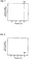
- Fig. 7 shows a result from a Fast Fourier Transform (FFT) analysis over the displacement P of the movable mirror 30.
- FFT Fast Fourier Transform
- FIG. 8 shows an FFT-analyzed result over the displacement output from the laser interferometer when the sampling frequency fs is changed to one time the modulation frequency fm from the above condition.
- the axis of abscissa is represented logarithmic. As shown in Fig. 9 , it can be found that the frequency component of the modulation frequency fm contained in the displacement P becomes extremely small (almost 0) if the sampling frequency fs is set at 2 times or below the modulation frequency fm. In contrast, if the sampling frequency fs exceeds 2 times, the frequency component of the modulation signal increases up to the modulation width of 1 %.
- the timing signal Sg8 and the frequency component of the modulation frequency fm contained in the displacement P are set to have a phase difference of "0°" therebetween (Symbol: El)
- sampling is executed at the timing when the frequency component of the modulation frequency fm contained in the displacement P becomes "0". Therefore, the frequency component of the modulation frequency fm can not be detected.
- timing signal Sg8 and the frequency component of the modulation frequency fm contained in the displacement P are set to have a phase difference of "90°" therebetween (Symbol: E2), sampling is executed at the timing whenever the modulation signal Sg4 reaches the maximum. Therefore, the frequency component of the modulation frequency fm can not be detected.
- Sampling is executed when the sampling frequency fs is set at 1/n the modulation frequency fm (n: a positive integer) . In this case, even if the timing signal Sg8 and the frequency component of the modulation frequency fm contained in the displacement P have a phase difference therebetween, sampling can be executed at the same phase. Therefore, the frequency component of the modulation frequency fm can not be detected.
- the timing signal producer 41 sets the sampling frequency fs at 1/n the modulation frequency fm (n: a positive integer) to produce the timing signal Sg8. Therefore, the laser interferometer according to the present embodiment can eliminate the frequency component of the modulation frequency fm (the influence by the modulation) contained in the length measurement result.
- the timing signal Sg8 and the frequency component of the modulation frequency fm contained in the displacement P are set to have a phase difference of "0°" therebetween (Symbol: F1), sampling is executed at the timing when the intensity of the modulation signal Sg4 becomes "0". Therefore, the frequency component of the modulation frequency fm can not be detected.
- phase difference is set at "90°"
- sampling is executed at the points where the frequency component of the modulation frequency fm contained in the displacement P reaches the maximum and the minimum. Therefore, the frequency component of the modulation frequency fm can be detected with the maximum amplitude.
- Fig. 12 shows a variation in frequency component of the modulation frequency fm contained in the displacement P associated with a variation in phase difference between the frequency component of the modulation frequency fm contained in the displacement P and the timing signal Sg8 (sampling frequency fs).
- the phase difference between the frequency component of the modulation frequency fm contained in the displacement P and the timing signal Sg8 periodically changes the frequency component of the modulation frequency fm such that the frequency component of the modulation frequency fm contained in the displacement P becomes "0" when the phase difference is 0° and 180°, as can be found.
- the timing signal producer 41 sets the sampling frequency fs at double or 1/n the modulation frequency fm (n: a positive integer) to produce the timing signal Sg8.
- the phase of the timing signal Sg8 is set so as to minimize the frequency component of the modulation frequency fm contained in the displacement P.
- a method for setting the phase of the timing signal Sg8 may comprise measuring the displacement ⁇ D2 of the movable mirror 30 first in accordance with the above procedure while keeping the movable mirror 30 in the fixed state.
- the displacement ⁇ D2 is herein observed to contain the frequency component of the modulation frequency fm as shown in Fig. 11 .
- the timing signal producer 41 sets the phase of the timing signal Sg8 so as to minimize the above frequency component of the modulation frequency fm contained in the displacement P.
- the frequency component of the modulation frequency fm (the influence by the modulation) contained in the length measurement result can be eliminated by setting the phase difference of the timing signal Sg8 appropriately.
- the sampling unit 40 executes sampling at a certain period to eliminate the frequency component of the modulation frequency fm (the influence by the modulation) as described above. Therefore, in the present embodiment, an expensive optical element such as an AOM and an EOM is not used and accordingly the production cost of the laser light source can be suppressed. Additionally, in the present embodiment, an optical element such as an AOM and an EOM is not used and accordingly the laser light source can not be complicated.
- control of the oscillation frequency of the laser light L1 is not limited to one that uses the saturated absorption lines of iodine.
Landscapes
- Physics & Mathematics (AREA)
- General Physics & Mathematics (AREA)
- Engineering & Computer Science (AREA)
- Automation & Control Theory (AREA)
- Optics & Photonics (AREA)
- Instruments For Measurement Of Length By Optical Means (AREA)
Claims (12)
- Ein Laserinterferometer zum Messen einer Länge basierend auf Laserlichtinterferenz, das Folgendes umfasst:
eine Laserquelle (10), die eingesetzt werden kann, um ein Laserlicht zu erzeugen, das mit einem Modulationssignal einer ersten Frequenz moduliert ist, wobei das Modulationssignal eine Sinuswelle ist; undeine Interferometereinheit (20), die eingesetzt werden kann, um das genannte Laserlicht von der genannten Laserquelle (10) auf ein Messziel (30) anzuwenden, um ein gemessenes Licht zu erzeugen, das Längenmessinformation enthält, und eingesetzt werden kann, um das genannte gemessene Licht an einem Fotorezeptor zu empfangen, um ein elektrisches Signal zu erzeugen, das Längenmessinformationen enthält,wobei das Laserinterferometer eine Abtasteinheit (40) umfasst, die eingesetzt werden kann, um das elektrische Signal synchron mit einem Zeitsignal einer zweiten Frequenz abzutasten, das auf der Basis des Modulationssignals der genannten ersten Frequenz erzeugt wird,dadurch gekennzeichnet, dass die genannte zweite Frequenz 1 / n der genannten ersten Frequenz ist, wobei n eine positive ganze Zahl ist. - Das Laserinterferometer entsprechend Anspruch 1, das zudem einen Filter umfasst, der eingesetzt werden kann, um das Modulationssignal zu erzeugen, das auf dem Zeitsignal basiert.
- Das Laserinterferometer entsprechend Anspruch 1 oder 2, wobei die genannte Laserquelle (10) eingesetzt werden kann, um die Zentralwellenlänge des genannten Laserlichts anzupassen, um auf eine bestimmte gesättigte Absorptionslinie von Jod aufzutreffen.
- Das Laserinterferometer entsprechend Anspruch 3, wobei die genannte Laserquelle (10) eingesetzt werden kann, um die genannte gesättigte Absorptionslinie entsprechend eines Differentialsignals dritter Ordnung eines elektrischen Signals basierend auf dem durch das Jod übertragenen Laserlichts zu spezifizieren.
- Ein Messverfahren zum Messen einer Länge basierend auf Laserlichtinterferenz, das Folgendes umfasst:
Erzeugen eines Laserlichts, das mit einem Modulationssignal einer ersten Frequenz (S101, S102) moduliert ist, wobei das Modulationssignal eine Sinuswelle ist; undAnwenden des genannten erzeugten Laserlichts auf ein Messziel, um ein gemessenes Licht zu erzeugen, das Längenmessinformation enthält, und Empfangen des genannten gemessenen Lichts an einem Fotorezeptor, um ein elektrisches Signal zu erzeugen, das Längenmessinformationen (S103) enthält,wobei das Verfahren das Abtasten des genannten elektrischen Signals synchron mit einem Zeitsignal einer zweiten Frequenz umfasst, das auf der Basis des genannten Modulationssignals der genannten ersten Frequenz (S104, S105) erzeugt wird,dadurch gekennzeichnet, dass die genannte zweite Frequenz 1 / n der genannten ersten Frequenz ist, wobei n eine positive ganze Zahl ist. - Das Messverfahren entsprechend Anspruch 5, das zudem das Erzeugen des Modulationssignals basierend auf dem Zeitsignal unter Verwenden eines Filters umfasst.
- Das Messverfahren entsprechend Anspruch 5 oder Anspruch 6, das zudem die Anpassung der Zentralwellenlänge des genannten Laserlichts umfasst, um auf eine bestimmte gesättigte Absorptionslinie von Jod aufzutreffen.
- Das Messverfahren entsprechend Anspruch 7, das zudem das Spezifizieren der genannten gesättigten Absorptionslinie entsprechend eines Differentialsignals dritter Ordnung eines elektrischen Signals basierend auf dem durch das Jod übertragenen Laserlichts umfasst.
- Ein Messprogramm zum Messen einer Länge basierend auf Laserlichtinterferenz, das die folgenden, auf einem Computer ausführbaren Schritte umfasst:
Erzeugen eines Laserlichts, das mit einem Modulationssignal einer ersten Frequenz (S101, S102) moduliert ist, wobei das Modulationssignal eine Sinuswelle ist; undAnwenden des genannten erzeugten Laserlichts auf ein Messziel, um ein gemessenes Licht zu erzeugen, das Längenmessinformation enthält, und Empfangen des genannten gemessenen Lichts an einem Fotorezeptor, um ein elektrisches Signal zu erzeugen, das Längenmessinformationen (S103) enthält,wobei das Programm den von einem Computer ausführbaren Schritt des Abtastens des genannten elektrischen Signals synchron mit einem Zeitsignal einer zweiten Frequenz umfasst, das auf der Basis des genannten Modulationssignals der genannten ersten Frequenz (S104, S105) erzeugt wird,dadurch gekennzeichnet, dass die genannte zweite Frequenz 1 / n der genannten ersten Frequenz ist, wobei n eine positive ganze Zahl ist. - Das Messprogramm entsprechend Anspruch 9, das zudem den von einem Computer ausführbaren Schritt des Erzeugens des Modulationssignals basierend auf dem Zeitsignal unter Verwenden eines Filters umfasst.
- Das Messprogramm entsprechend Anspruch 9 oder Anspruch 10, das zudem den von einem Computer ausführbaren Schritt der Anpassung der Zentralwellenlänge des genannten Laserlichts umfasst, um auf eine bestimmte gesättigte Absorptionslinie von Jod aufzutreffen.
- Das Messprogramm entsprechend Anspruch 11, das zudem den von einem Computer ausführbaren Schritt des Spezifizierens der genannten gesättigten Absorptionslinie entsprechend eines Differentialsignals dritter Ordnung eines elektrischen Signals basierend auf dem durch das Jod übertragenen Laserlichts umfasst..
Applications Claiming Priority (1)
| Application Number | Priority Date | Filing Date | Title |
|---|---|---|---|
| JP2008099095A JP5433846B2 (ja) | 2008-04-07 | 2008-04-07 | レーザ干渉測長装置及びレーザ干渉測長方法 |
Publications (2)
| Publication Number | Publication Date |
|---|---|
| EP2108918A1 EP2108918A1 (de) | 2009-10-14 |
| EP2108918B1 true EP2108918B1 (de) | 2018-12-12 |
Family
ID=40791528
Family Applications (1)
| Application Number | Title | Priority Date | Filing Date |
|---|---|---|---|
| EP09157375.8A Not-in-force EP2108918B1 (de) | 2008-04-07 | 2009-04-06 | Laserinterferometer, Messverfahren und Messprogramm |
Country Status (2)
| Country | Link |
|---|---|
| EP (1) | EP2108918B1 (de) |
| JP (1) | JP5433846B2 (de) |
Families Citing this family (21)
| Publication number | Priority date | Publication date | Assignee | Title |
|---|---|---|---|---|
| JP5541901B2 (ja) | 2009-10-30 | 2014-07-09 | 矢崎総業株式会社 | 止水処理方法および絶縁被覆電線 |
| JP5570905B2 (ja) * | 2010-08-05 | 2014-08-13 | 株式会社ミツトヨ | 周波数安定化レーザー光源、および、波長校正方法 |
| CN101968658B (zh) * | 2010-09-27 | 2012-07-11 | 中国计量学院 | 基于外差式激光干涉仪的纳米静态锁定定位方法 |
| JP5695426B2 (ja) * | 2011-01-07 | 2015-04-08 | 株式会社ミツトヨ | レーザ干渉測長装置の絶対距離測定方法、及びレーザ干渉測長装置 |
| CN105043245B (zh) * | 2015-05-29 | 2018-04-13 | 北方民族大学 | 一种对比式抗干扰平面反射镜激光干涉仪及标定方法和测量方法 |
| CN105004263B (zh) * | 2015-05-29 | 2017-12-05 | 北方民族大学 | 一种对比式抗干扰微动平面反射镜激光干涉仪及标定方法和测量方法 |
| CN104880147B (zh) * | 2015-06-29 | 2017-07-21 | 成都信息工程大学 | 一种磁性微位移平台式角反射镜激光干涉仪的标定方法和测量方法 |
| CN104964641B (zh) * | 2015-06-29 | 2017-10-10 | 成都信息工程大学 | 一种磁性微位移平台式级联阶梯角反射镜激光干涉仪及标定方法和测量方法 |
| CN104897049B (zh) * | 2015-06-29 | 2017-07-28 | 北方民族大学 | 一种磁性微位移平台式平面反射镜激光干涉仪的标定方法和测量方法 |
| CN104930968B (zh) * | 2015-06-29 | 2017-09-29 | 成都信息工程大学 | 一种磁性微位移平台式阶梯平面反射镜激光干涉仪及标定方法和测量方法 |
| CN104964642B (zh) * | 2015-06-29 | 2017-07-21 | 成都信息工程大学 | 一种磁性微位移平台式阶梯角反射镜激光干涉仪的标定方法和测量方法 |
| CN105352435B (zh) * | 2015-11-27 | 2018-03-27 | 成都信息工程大学 | 采用激光波长修正式角反射镜激光干涉仪的测量方法 |
| CN105333817B (zh) * | 2015-11-27 | 2018-06-01 | 成都信息工程大学 | 采用激光波长修正式平面反射镜激光干涉仪的测量方法 |
| CN105509636B (zh) * | 2015-11-27 | 2018-02-06 | 成都信息工程大学 | 一种采用波长修正式多光束角阶梯反射镜激光干涉仪的测量方法 |
| CN105371755B (zh) * | 2015-11-27 | 2018-02-06 | 成都信息工程大学 | 一种采用波长修正式多光束阶梯平面反射镜激光干涉仪的激光波长修正方法 |
| CN105277118B (zh) * | 2015-11-27 | 2018-03-27 | 成都信息工程大学 | 一种采用激光波长修正式角反射镜激光干涉仪的激光波长修正方法 |
| CN105509637B (zh) * | 2015-11-27 | 2018-02-06 | 成都信息工程大学 | 一种采用激光波长修正式平面反射镜激光干涉仪的激光波长修正方法 |
| CN105300275B (zh) * | 2015-11-27 | 2018-02-06 | 成都信息工程大学 | 一种采用波长修正式多光束阶梯平面反射镜激光干涉仪的测量方法 |
| CN105371753B (zh) * | 2015-11-27 | 2018-03-27 | 成都信息工程大学 | 一种采用波长修正式多光束角阶梯反射镜激光干涉仪的激光波长修正方法 |
| KR20210013577A (ko) | 2018-05-18 | 2021-02-04 | 더 리젠츠 오브 더 유니버시티 오브 미시건 | 주파수 변조 간섭계를 위한 경로 변동 모니터링 |
| JP7658221B2 (ja) * | 2021-08-31 | 2025-04-08 | セイコーエプソン株式会社 | レーザー干渉計 |
Family Cites Families (13)
| Publication number | Priority date | Publication date | Assignee | Title |
|---|---|---|---|---|
| JPH0749922B2 (ja) * | 1987-08-05 | 1995-05-31 | 松下電器産業株式会社 | 光計測装置 |
| US4886363A (en) * | 1988-09-06 | 1989-12-12 | Eastman Kodak Company | Quadratic frequency modulated absolute distance measuring interferometry |
| JP2940559B2 (ja) * | 1990-07-31 | 1999-08-25 | オークマ株式会社 | 変位検出装置 |
| JPH06167304A (ja) * | 1992-11-30 | 1994-06-14 | Hide Hosoe | 変位計 |
| JPH09113217A (ja) * | 1995-10-13 | 1997-05-02 | Hoya Corp | 光ヘテロダイン式変位量検出装置 |
| JP3552386B2 (ja) * | 1996-02-20 | 2004-08-11 | 株式会社日本自動車部品総合研究所 | レーザ干渉変位計 |
| US6396069B1 (en) * | 1999-06-25 | 2002-05-28 | Macpherson David C. | Topographer for real time ablation feedback having synthetic wavelength generators |
| JP3245135B2 (ja) * | 1999-08-26 | 2002-01-07 | 科学技術振興事業団 | 光計測装置 |
| JP2001274495A (ja) * | 2000-03-27 | 2001-10-05 | Neoark Corp | レーザ光発振周波数のオートロック方法 |
| JP3628615B2 (ja) * | 2001-01-16 | 2005-03-16 | 独立行政法人科学技術振興機構 | ヘテロダインビート画像同期測定装置 |
| JP4409334B2 (ja) * | 2004-03-31 | 2010-02-03 | 株式会社トプコン | 光画像計測装置 |
| JP4633423B2 (ja) * | 2004-09-15 | 2011-02-16 | 株式会社トプコン | 光画像計測装置 |
| JP4501000B2 (ja) * | 2004-10-01 | 2010-07-14 | 国立大学法人 新潟大学 | レーザ干渉変位測定方法およびレーザ干渉変位測定装置 |
-
2008
- 2008-04-07 JP JP2008099095A patent/JP5433846B2/ja not_active Expired - Fee Related
-
2009
- 2009-04-06 EP EP09157375.8A patent/EP2108918B1/de not_active Not-in-force
Also Published As
| Publication number | Publication date |
|---|---|
| EP2108918A1 (de) | 2009-10-14 |
| JP5433846B2 (ja) | 2014-03-05 |
| JP2009250786A (ja) | 2009-10-29 |
Similar Documents
| Publication | Publication Date | Title |
|---|---|---|
| EP2108918B1 (de) | Laserinterferometer, Messverfahren und Messprogramm | |
| US8913636B2 (en) | Precise broadband frequency modulated laser | |
| CN113661382B (zh) | 色散测量装置、脉冲光源、色散测量方法和色散补偿方法 | |
| US11721948B2 (en) | Swept light source and drive data generation method and optical deflector for swept light source | |
| US9115971B2 (en) | Measuring apparatus | |
| US8923349B2 (en) | Fourier domain mode locking: method and apparatus for control and improved performance | |
| US8078060B2 (en) | Optical synchronization system for femtosecond X-ray sources | |
| US20130229662A1 (en) | Chromatic dispersion measurement device and chromatic dispersion measurement method using the same | |
| US20130146769A1 (en) | Optical pulse generating apparatus, terahertz spectroscopy apparatus, and tomography apparatus | |
| JP2010505095A (ja) | 合成波長を生成する方法および装置 | |
| JP6074764B2 (ja) | 光周波数コム安定化光源および方法 | |
| US20210349213A1 (en) | Arbitrary optical waveform generation utilizing frequency discriminators | |
| KR20130015893A (ko) | 펄스 레이저 반복률 주사 기반 고속 고정밀 표면형상 측정 간섭계 | |
| US20130088722A1 (en) | Measurement apparatus | |
| US20240085538A1 (en) | Arbitrary Optical Waveform Generation Utilizing Frequency Discriminators | |
| WO2018159445A1 (ja) | 光コムの制御方法及び光コムの制御装置 | |
| JP2010002244A (ja) | レーザ干渉測長装置及びレーザ干渉測長方法 | |
| WO2006018897A1 (ja) | レーザ位相差検出装置およびレーザ位相制御装置 | |
| JP7731097B2 (ja) | シングルコム分光装置 | |
| US7876449B2 (en) | Laser interferometer | |
| JP2012132711A (ja) | パルス間位相ズレ測定装置、オフセット周波数制御装置、パルス間位相ズレ測定方法、オフセット周波数制御方法 | |
| JP2011249400A (ja) | レーザ光源の調整システム、及びレーザ光源の調整方法 | |
| JP2014209517A (ja) | 光周波数コム発生装置および光周波数コムの周波数安定化方法 | |
| JP2023016496A (ja) | ラムゼー分光装置、光格子時計およびラムゼー分光方法 | |
| US20060263007A1 (en) | Method for sequentially writing fiber bragg grating by using real-time side-diffraction optical fiber position monitoring |
Legal Events
| Date | Code | Title | Description |
|---|---|---|---|
| PUAI | Public reference made under article 153(3) epc to a published international application that has entered the european phase |
Free format text: ORIGINAL CODE: 0009012 |
|
| AK | Designated contracting states |
Kind code of ref document: A1 Designated state(s): AT BE BG CH CY CZ DE DK EE ES FI FR GB GR HR HU IE IS IT LI LT LU LV MC MK MT NL NO PL PT RO SE SI SK TR |
|
| 17P | Request for examination filed |
Effective date: 20100413 |
|
| 17Q | First examination report despatched |
Effective date: 20161017 |
|
| STAA | Information on the status of an ep patent application or granted ep patent |
Free format text: STATUS: EXAMINATION IS IN PROGRESS |
|
| GRAP | Despatch of communication of intention to grant a patent |
Free format text: ORIGINAL CODE: EPIDOSNIGR1 |
|
| STAA | Information on the status of an ep patent application or granted ep patent |
Free format text: STATUS: GRANT OF PATENT IS INTENDED |
|
| INTG | Intention to grant announced |
Effective date: 20180702 |
|
| GRAS | Grant fee paid |
Free format text: ORIGINAL CODE: EPIDOSNIGR3 |
|
| GRAA | (expected) grant |
Free format text: ORIGINAL CODE: 0009210 |
|
| STAA | Information on the status of an ep patent application or granted ep patent |
Free format text: STATUS: THE PATENT HAS BEEN GRANTED |
|
| AK | Designated contracting states |
Kind code of ref document: B1 Designated state(s): AT BE BG CH CY CZ DE DK EE ES FI FR GB GR HR HU IE IS IT LI LT LU LV MC MK MT NL NO PL PT RO SE SI SK TR |
|
| REG | Reference to a national code |
Ref country code: GB Ref legal event code: FG4D |
|
| REG | Reference to a national code |
Ref country code: CH Ref legal event code: EP |
|
| REG | Reference to a national code |
Ref country code: AT Ref legal event code: REF Ref document number: 1076603 Country of ref document: AT Kind code of ref document: T Effective date: 20181215 |
|
| REG | Reference to a national code |
Ref country code: DE Ref legal event code: R096 Ref document number: 602009056140 Country of ref document: DE |
|
| REG | Reference to a national code |
Ref country code: IE Ref legal event code: FG4D |
|
| REG | Reference to a national code |
Ref country code: NL Ref legal event code: MP Effective date: 20181212 |
|
| REG | Reference to a national code |
Ref country code: LT Ref legal event code: MG4D |
|
| PG25 | Lapsed in a contracting state [announced via postgrant information from national office to epo] |
Ref country code: LV Free format text: LAPSE BECAUSE OF FAILURE TO SUBMIT A TRANSLATION OF THE DESCRIPTION OR TO PAY THE FEE WITHIN THE PRESCRIBED TIME-LIMIT Effective date: 20181212 Ref country code: ES Free format text: LAPSE BECAUSE OF FAILURE TO SUBMIT A TRANSLATION OF THE DESCRIPTION OR TO PAY THE FEE WITHIN THE PRESCRIBED TIME-LIMIT Effective date: 20181212 Ref country code: LT Free format text: LAPSE BECAUSE OF FAILURE TO SUBMIT A TRANSLATION OF THE DESCRIPTION OR TO PAY THE FEE WITHIN THE PRESCRIBED TIME-LIMIT Effective date: 20181212 Ref country code: NO Free format text: LAPSE BECAUSE OF FAILURE TO SUBMIT A TRANSLATION OF THE DESCRIPTION OR TO PAY THE FEE WITHIN THE PRESCRIBED TIME-LIMIT Effective date: 20190312 Ref country code: FI Free format text: LAPSE BECAUSE OF FAILURE TO SUBMIT A TRANSLATION OF THE DESCRIPTION OR TO PAY THE FEE WITHIN THE PRESCRIBED TIME-LIMIT Effective date: 20181212 Ref country code: BG Free format text: LAPSE BECAUSE OF FAILURE TO SUBMIT A TRANSLATION OF THE DESCRIPTION OR TO PAY THE FEE WITHIN THE PRESCRIBED TIME-LIMIT Effective date: 20190312 Ref country code: HR Free format text: LAPSE BECAUSE OF FAILURE TO SUBMIT A TRANSLATION OF THE DESCRIPTION OR TO PAY THE FEE WITHIN THE PRESCRIBED TIME-LIMIT Effective date: 20181212 |
|
| REG | Reference to a national code |
Ref country code: AT Ref legal event code: MK05 Ref document number: 1076603 Country of ref document: AT Kind code of ref document: T Effective date: 20181212 |
|
| PG25 | Lapsed in a contracting state [announced via postgrant information from national office to epo] |
Ref country code: GR Free format text: LAPSE BECAUSE OF FAILURE TO SUBMIT A TRANSLATION OF THE DESCRIPTION OR TO PAY THE FEE WITHIN THE PRESCRIBED TIME-LIMIT Effective date: 20190313 Ref country code: SE Free format text: LAPSE BECAUSE OF FAILURE TO SUBMIT A TRANSLATION OF THE DESCRIPTION OR TO PAY THE FEE WITHIN THE PRESCRIBED TIME-LIMIT Effective date: 20181212 |
|
| PG25 | Lapsed in a contracting state [announced via postgrant information from national office to epo] |
Ref country code: NL Free format text: LAPSE BECAUSE OF FAILURE TO SUBMIT A TRANSLATION OF THE DESCRIPTION OR TO PAY THE FEE WITHIN THE PRESCRIBED TIME-LIMIT Effective date: 20181212 |
|
| PG25 | Lapsed in a contracting state [announced via postgrant information from national office to epo] |
Ref country code: PL Free format text: LAPSE BECAUSE OF FAILURE TO SUBMIT A TRANSLATION OF THE DESCRIPTION OR TO PAY THE FEE WITHIN THE PRESCRIBED TIME-LIMIT Effective date: 20181212 Ref country code: IT Free format text: LAPSE BECAUSE OF FAILURE TO SUBMIT A TRANSLATION OF THE DESCRIPTION OR TO PAY THE FEE WITHIN THE PRESCRIBED TIME-LIMIT Effective date: 20181212 Ref country code: CZ Free format text: LAPSE BECAUSE OF FAILURE TO SUBMIT A TRANSLATION OF THE DESCRIPTION OR TO PAY THE FEE WITHIN THE PRESCRIBED TIME-LIMIT Effective date: 20181212 Ref country code: PT Free format text: LAPSE BECAUSE OF FAILURE TO SUBMIT A TRANSLATION OF THE DESCRIPTION OR TO PAY THE FEE WITHIN THE PRESCRIBED TIME-LIMIT Effective date: 20190412 |
|
| PG25 | Lapsed in a contracting state [announced via postgrant information from national office to epo] |
Ref country code: RO Free format text: LAPSE BECAUSE OF FAILURE TO SUBMIT A TRANSLATION OF THE DESCRIPTION OR TO PAY THE FEE WITHIN THE PRESCRIBED TIME-LIMIT Effective date: 20181212 Ref country code: IS Free format text: LAPSE BECAUSE OF FAILURE TO SUBMIT A TRANSLATION OF THE DESCRIPTION OR TO PAY THE FEE WITHIN THE PRESCRIBED TIME-LIMIT Effective date: 20190412 Ref country code: EE Free format text: LAPSE BECAUSE OF FAILURE TO SUBMIT A TRANSLATION OF THE DESCRIPTION OR TO PAY THE FEE WITHIN THE PRESCRIBED TIME-LIMIT Effective date: 20181212 Ref country code: SK Free format text: LAPSE BECAUSE OF FAILURE TO SUBMIT A TRANSLATION OF THE DESCRIPTION OR TO PAY THE FEE WITHIN THE PRESCRIBED TIME-LIMIT Effective date: 20181212 |
|
| REG | Reference to a national code |
Ref country code: DE Ref legal event code: R097 Ref document number: 602009056140 Country of ref document: DE |
|
| PLBE | No opposition filed within time limit |
Free format text: ORIGINAL CODE: 0009261 |
|
| STAA | Information on the status of an ep patent application or granted ep patent |
Free format text: STATUS: NO OPPOSITION FILED WITHIN TIME LIMIT |
|
| PG25 | Lapsed in a contracting state [announced via postgrant information from national office to epo] |
Ref country code: DK Free format text: LAPSE BECAUSE OF FAILURE TO SUBMIT A TRANSLATION OF THE DESCRIPTION OR TO PAY THE FEE WITHIN THE PRESCRIBED TIME-LIMIT Effective date: 20181212 Ref country code: AT Free format text: LAPSE BECAUSE OF FAILURE TO SUBMIT A TRANSLATION OF THE DESCRIPTION OR TO PAY THE FEE WITHIN THE PRESCRIBED TIME-LIMIT Effective date: 20181212 Ref country code: SI Free format text: LAPSE BECAUSE OF FAILURE TO SUBMIT A TRANSLATION OF THE DESCRIPTION OR TO PAY THE FEE WITHIN THE PRESCRIBED TIME-LIMIT Effective date: 20181212 |
|
| 26N | No opposition filed |
Effective date: 20190913 |
|
| REG | Reference to a national code |
Ref country code: CH Ref legal event code: PL |
|
| REG | Reference to a national code |
Ref country code: BE Ref legal event code: MM Effective date: 20190430 |
|
| PG25 | Lapsed in a contracting state [announced via postgrant information from national office to epo] |
Ref country code: LU Free format text: LAPSE BECAUSE OF NON-PAYMENT OF DUE FEES Effective date: 20190406 Ref country code: MC Free format text: LAPSE BECAUSE OF FAILURE TO SUBMIT A TRANSLATION OF THE DESCRIPTION OR TO PAY THE FEE WITHIN THE PRESCRIBED TIME-LIMIT Effective date: 20181212 |
|
| PG25 | Lapsed in a contracting state [announced via postgrant information from national office to epo] |
Ref country code: LI Free format text: LAPSE BECAUSE OF NON-PAYMENT OF DUE FEES Effective date: 20190430 Ref country code: CH Free format text: LAPSE BECAUSE OF NON-PAYMENT OF DUE FEES Effective date: 20190430 |
|
| PG25 | Lapsed in a contracting state [announced via postgrant information from national office to epo] |
Ref country code: FR Free format text: LAPSE BECAUSE OF NON-PAYMENT OF DUE FEES Effective date: 20190430 Ref country code: BE Free format text: LAPSE BECAUSE OF NON-PAYMENT OF DUE FEES Effective date: 20190430 |
|
| PG25 | Lapsed in a contracting state [announced via postgrant information from national office to epo] |
Ref country code: TR Free format text: LAPSE BECAUSE OF FAILURE TO SUBMIT A TRANSLATION OF THE DESCRIPTION OR TO PAY THE FEE WITHIN THE PRESCRIBED TIME-LIMIT Effective date: 20181212 |
|
| PG25 | Lapsed in a contracting state [announced via postgrant information from national office to epo] |
Ref country code: IE Free format text: LAPSE BECAUSE OF NON-PAYMENT OF DUE FEES Effective date: 20190406 |
|
| PG25 | Lapsed in a contracting state [announced via postgrant information from national office to epo] |
Ref country code: CY Free format text: LAPSE BECAUSE OF FAILURE TO SUBMIT A TRANSLATION OF THE DESCRIPTION OR TO PAY THE FEE WITHIN THE PRESCRIBED TIME-LIMIT Effective date: 20181212 |
|
| PG25 | Lapsed in a contracting state [announced via postgrant information from national office to epo] |
Ref country code: HU Free format text: LAPSE BECAUSE OF FAILURE TO SUBMIT A TRANSLATION OF THE DESCRIPTION OR TO PAY THE FEE WITHIN THE PRESCRIBED TIME-LIMIT; INVALID AB INITIO Effective date: 20090406 Ref country code: MT Free format text: LAPSE BECAUSE OF FAILURE TO SUBMIT A TRANSLATION OF THE DESCRIPTION OR TO PAY THE FEE WITHIN THE PRESCRIBED TIME-LIMIT Effective date: 20181212 |
|
| PGFP | Annual fee paid to national office [announced via postgrant information from national office to epo] |
Ref country code: DE Payment date: 20210420 Year of fee payment: 13 |
|
| PGFP | Annual fee paid to national office [announced via postgrant information from national office to epo] |
Ref country code: GB Payment date: 20210421 Year of fee payment: 13 |
|
| PG25 | Lapsed in a contracting state [announced via postgrant information from national office to epo] |
Ref country code: MK Free format text: LAPSE BECAUSE OF FAILURE TO SUBMIT A TRANSLATION OF THE DESCRIPTION OR TO PAY THE FEE WITHIN THE PRESCRIBED TIME-LIMIT Effective date: 20181212 |
|
| REG | Reference to a national code |
Ref country code: DE Ref legal event code: R119 Ref document number: 602009056140 Country of ref document: DE |
|
| GBPC | Gb: european patent ceased through non-payment of renewal fee |
Effective date: 20220406 |
|
| PG25 | Lapsed in a contracting state [announced via postgrant information from national office to epo] |
Ref country code: GB Free format text: LAPSE BECAUSE OF NON-PAYMENT OF DUE FEES Effective date: 20220406 Ref country code: DE Free format text: LAPSE BECAUSE OF NON-PAYMENT OF DUE FEES Effective date: 20221103 |