EP2108180B1 - Monture de dispositif ayant un axe de basculement pouvant etre selectivement positionne - Google Patents
Monture de dispositif ayant un axe de basculement pouvant etre selectivement positionne Download PDFInfo
- Publication number
- EP2108180B1 EP2108180B1 EP08705455.7A EP08705455A EP2108180B1 EP 2108180 B1 EP2108180 B1 EP 2108180B1 EP 08705455 A EP08705455 A EP 08705455A EP 2108180 B1 EP2108180 B1 EP 2108180B1
- Authority
- EP
- European Patent Office
- Prior art keywords
- tilt axis
- display
- guide
- guide structure
- guide member
- Prior art date
- Legal status (The legal status is an assumption and is not a legal conclusion. Google has not performed a legal analysis and makes no representation as to the accuracy of the status listed.)
- Active
Links
- 230000000694 effects Effects 0.000 claims description 3
- 230000005484 gravity Effects 0.000 description 10
- 230000000712 assembly Effects 0.000 description 2
- 238000000429 assembly Methods 0.000 description 2
- 210000005069 ears Anatomy 0.000 description 2
- 238000004519 manufacturing process Methods 0.000 description 2
- 238000000034 method Methods 0.000 description 2
- 101100136092 Drosophila melanogaster peng gene Proteins 0.000 description 1
- 230000003247 decreasing effect Effects 0.000 description 1
- 230000008030 elimination Effects 0.000 description 1
- 238000003379 elimination reaction Methods 0.000 description 1
- 238000009434 installation Methods 0.000 description 1
- 230000000717 retained effect Effects 0.000 description 1
Images


Classifications
-
- F—MECHANICAL ENGINEERING; LIGHTING; HEATING; WEAPONS; BLASTING
- F16—ENGINEERING ELEMENTS AND UNITS; GENERAL MEASURES FOR PRODUCING AND MAINTAINING EFFECTIVE FUNCTIONING OF MACHINES OR INSTALLATIONS; THERMAL INSULATION IN GENERAL
- F16M—FRAMES, CASINGS OR BEDS OF ENGINES, MACHINES OR APPARATUS, NOT SPECIFIC TO ENGINES, MACHINES OR APPARATUS PROVIDED FOR ELSEWHERE; STANDS; SUPPORTS
- F16M13/00—Other supports for positioning apparatus or articles; Means for steadying hand-held apparatus or articles
- F16M13/02—Other supports for positioning apparatus or articles; Means for steadying hand-held apparatus or articles for supporting on, or attaching to, an object, e.g. tree, gate, window-frame, cycle
-
- F—MECHANICAL ENGINEERING; LIGHTING; HEATING; WEAPONS; BLASTING
- F16—ENGINEERING ELEMENTS AND UNITS; GENERAL MEASURES FOR PRODUCING AND MAINTAINING EFFECTIVE FUNCTIONING OF MACHINES OR INSTALLATIONS; THERMAL INSULATION IN GENERAL
- F16M—FRAMES, CASINGS OR BEDS OF ENGINES, MACHINES OR APPARATUS, NOT SPECIFIC TO ENGINES, MACHINES OR APPARATUS PROVIDED FOR ELSEWHERE; STANDS; SUPPORTS
- F16M11/00—Stands or trestles as supports for apparatus or articles placed thereon Stands for scientific apparatus such as gravitational force meters
- F16M11/02—Heads
- F16M11/04—Means for attachment of apparatus; Means allowing adjustment of the apparatus relatively to the stand
- F16M11/06—Means for attachment of apparatus; Means allowing adjustment of the apparatus relatively to the stand allowing pivoting
- F16M11/10—Means for attachment of apparatus; Means allowing adjustment of the apparatus relatively to the stand allowing pivoting around a horizontal axis
-
- F—MECHANICAL ENGINEERING; LIGHTING; HEATING; WEAPONS; BLASTING
- F16—ENGINEERING ELEMENTS AND UNITS; GENERAL MEASURES FOR PRODUCING AND MAINTAINING EFFECTIVE FUNCTIONING OF MACHINES OR INSTALLATIONS; THERMAL INSULATION IN GENERAL
- F16M—FRAMES, CASINGS OR BEDS OF ENGINES, MACHINES OR APPARATUS, NOT SPECIFIC TO ENGINES, MACHINES OR APPARATUS PROVIDED FOR ELSEWHERE; STANDS; SUPPORTS
- F16M11/00—Stands or trestles as supports for apparatus or articles placed thereon Stands for scientific apparatus such as gravitational force meters
- F16M11/20—Undercarriages with or without wheels
- F16M11/2092—Undercarriages with or without wheels comprising means allowing depth adjustment, i.e. forward-backward translation of the head relatively to the undercarriage
-
- F—MECHANICAL ENGINEERING; LIGHTING; HEATING; WEAPONS; BLASTING
- F16—ENGINEERING ELEMENTS AND UNITS; GENERAL MEASURES FOR PRODUCING AND MAINTAINING EFFECTIVE FUNCTIONING OF MACHINES OR INSTALLATIONS; THERMAL INSULATION IN GENERAL
- F16M—FRAMES, CASINGS OR BEDS OF ENGINES, MACHINES OR APPARATUS, NOT SPECIFIC TO ENGINES, MACHINES OR APPARATUS PROVIDED FOR ELSEWHERE; STANDS; SUPPORTS
- F16M11/00—Stands or trestles as supports for apparatus or articles placed thereon Stands for scientific apparatus such as gravitational force meters
- F16M11/20—Undercarriages with or without wheels
- F16M11/24—Undercarriages with or without wheels changeable in height or length of legs, also for transport only, e.g. by means of tubes screwed into each other
Definitions
- the present invention relates to electronic displays and devices and more particularly to mounting devices for electronic displays and devices.
- Flat panel electronic display devices such as LCD and plasma displays offer many advantages over conventional CRT and rear projection displays, such as improved picture resolution, elimination of screen flicker, and greatly decreased physical dimensions. Consequently, flat panel displays are becoming commonplace in business and residential settings.
- Some prior adjustably positionable mounts include various arrangements of brackets and arms to enable tilting of the display screen. Examples of such tilt mounts are disclosed in U.S Patent No. 6752363 to Boele and U.S. Published Patent Application No. US20020033436A1 by Peng, et. al.
- a drawback of such simple tilt devices wherein the tilt axis passes through the mount behind the display is that the display tends to tip forward or backward about the tilt axis unless it is held in the desired position with friction or other mechanical locking devices.
- large flat panel display devices, particularly plasma displays can be quite heavy and unwieldy, it can be difficult for an individual to simultaneously lift the display in the desired position and manipulate the mechanical locking device to fix the display in position.
- a mounting system for an electronic display device includes a support structure adapted to attach to a fixed structure and a display interface operably coupled with the support structure.
- the display interface includes an interface member presenting a display mounting surface for receiving the electronic display thereon, and a tilt head assembly defining a substantially horizontal tilt axis oriented generally parallel with, and spaced apart from, the display mounting surface. When the electronic display device is received on the display mounting surface, the tilt axis extends through the electronic display device.
- the tilt head assembly includes a control mechanism for selectively shifting the tilt axis between a first location spaced apart a first distance from the display mounting surface and a second location spaced apart a second distance from the display mounting surface, wherein the second distance is greater than the first distance.
- the tilt head assembly of the system includes a first carrier having at least one follower and a first guide member defining a first guide structure positioned along an arc centered on the tilt axis.
- the at least one follower and the first guide structure are engaged and together define a range of tilt motion about the tilt axis.
- the control mechanism is operably coupled with the first guide member to selectively shift an orientation of the first guide structure to thereby effect selective shifting of the tilt axis between the first and second locations.
- the guide structure may be curved, generally straight, angular or any other shape.
- the guide structure may be a slot, groove, channel, ridge, cam edge, or any other structure.
- the system may include a second guide member defining a second guide structure positioned along the arc centered on the tilt axis.
- the first carrier includes at least a pair of followers. One of the pair of followers is engaged with the first guide structure and the other of the pair of followers is engaged with the second guide structure.
- the first and second guide members may be operably coupled such that when the orientation of first guide structure is shifted with the control mechanism, an orientation of the second guide member is also shifted.
- a mounting system for an electronic display device includes a support structure adapted to attach to a fixed structure and a display interface operably coupled with the support structure.
- the display interface generally includes an interface member presenting a display mounting surface for receiving the electronic display thereon and a tilt head assembly defining a substantially horizontal tilt axis forward of the display mounting surface.
- the tilt head assembly includes means for selectively shifting the tilt axis between a first location spaced apart a first distance from the display mounting surface and a second location spaced apart a second distance from the display mounting surface, wherein the second distance is greater than the first distance.
- An embodiment of the invention may also include an electronic display system.
- the system includes an electronic display device with a front side presenting a display screen and an opposing rear side and a mount for attaching the electronic display device to a fixed structure.
- the mount includes a support structure adapted to attach to a fixed structure and a display interface operably coupled with the support structure.
- the display interface has an interface member presenting a display mounting surface confronting the rear side of the electronic display device and a tilt head assembly defining a substantially horizontal tilt axis oriented generally parallel with and spaced apart from the display mounting surface such that the tilt axis extends through the electronic display device.
- the tilt head assembly includes a control mechanism for selectively shifting the tilt axis between a first location spaced apart a first distance from the display mounting surface and a second location spaced apart a second distance from the display mounting surface, wherein the second distance is greater than the first distance.
- An embodiment which is not part of the invention may also include a method for mounting an electronic display on a fixed structure with a mount defining a virtual tilt axis forward of the mount.
- the method may include adjusting the mount to shift the location of the virtual tilt axis so as to coincide with the center of gravity of the electronic display.
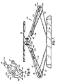
- Mount 30 generally includes structure interface 32, cantilever support 34 and device interface 36.
- Structure interface 32 generally includes mounting bars 38, 39, which attach to fixed structure 40 such as planar wall surface 42, and upright columns 44 extending between mounting bars 38, 39.
- Cantilever support 34 generally includes articulating arm assemblies 46, 48, and height adjustment mechanism 50.
- Each articulating arm assembly 46, 48 generally includes lower arm 52 and upper arm 54 connected at pivot 56.
- Each lower arm 52 includes sleeve 58 received on one of upright columns 44 and vertically slidable thereon.
- Height adjustment mechanism 50 generally includes base portion 62 on mounting bar 39 and upper portion 64 operably coupled with sleeves 58. Threaded coupler 66 extends between base portion 62 and upper portion 64 and receives jacking nut 68, which bears on the underside of upper portion 64.
- articulating arm assemblies may be translated together vertically by rotating jacking nut 68 up or down on threaded coupler 66, thereby sliding upper portion 64 and sleeves 58 up or down on upright columns 44.
- Further details of embodiments of structure interface 32 and cantilever support 34 are disclosed in U.S. Patent Application No. 11/447,226 , hereby fully incorporated herein by reference.
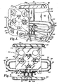
- Device interface 36 in an embodiment depicted in Figs. 8-18 , generally includes carrier 70, upper guide member 72, lower guide member 74, follower member 76, and interface plate 78.
- Carrier 70 generally includes back plane 79 with spaced-apart lateral flanges 80, 82, and spaced apart horizontal flanges 84, 86, projecting therefrom.
- Upper aperture 88 and lower aperture 90 are defined in lateral flange 80 in registry with corresponding upper and lower apertures 88, 90, defined in lateral flange 82.
- Each lateral flange 80, 82 defines a pair of facing shoulders 91a, 91 b.
- Horizontal flange 84 defines round aperture 92 and oblong aperture 94, while horizontal flange 86 defines round aperture 96 in registry with aperture 92.
- attachment channels 60, 61 generally include back wall 98 with projecting upper and lower flanges 100, 102, respectively.
- Apertures 104 are defined in each of upper and lower flanges 100, 102 proximate outer end 106, each for receiving a fastener 108 to fix each attachment channel 60, 61, to one of upper arms 54.
- Proximate inner end 110, upper flange 100 defines aperture 112 in registry with aperture 114 defined in lower flange 102.
- attachment channels 60, 61 are positioned so as to overlap, with apertures 112 and 114 in registry.
- Bushing 116 is received through apertures 112 and bushing 118 is received through apertures 114.
- Bushings 116, 118 together define bore 120, which is disposed in registry with apertures 92, 96, in horizontal flanges 84, 86 of carrier 70.
- Bolt 122 is received through apertures 92, 96, and bore 120, and is secured in place with nut 124.
- Attachment channel 60 is received between facing shoulders 91a, 91b, of lateral flange 80 with upper flange 100 confronting shoulder 91a and lower flange 102 confronting shoulder 91 b.
- carrier 70, and each of attachment channels 60, 61, and the upper arms 54 attached thereto are pivotable about bolt 122. Accordingly, a user may push or pull on device interface 36, which causes arms 52, 54, to pivot at sleeves 58, pivot 56 and at bolt 122.
- the articulating arrangement of arms 52, 54, and the pivotal connections of sleeves 58 with upright columns 44 of attachment channels 60, 61, with carrier 70 at bolt 122, enable the device interface and a display attached thereto to be selectively positioned laterally and inward and outward relative to the fixed structure 40.
- upper guide member 72 generally includes a pair of lateral walls 126, 128, connected by upper wall 130.
- Lateral wall 126 defines apertures 132, 134, in registry with apertures 136, 138, respectively, defined in lateral wall 128.
- Each lateral wall 126, 128, also defines a guide structure in the form of a slot 140, 142. Further, positioning tabs 144, 146, are defined at the bottom tips 148, 150, of each of lateral walls 126, 128 respectively.
- Pivot pin 152 extends through upper apertures 88 of carrier 70 and apertures 134, 138, of upper guide member 72 to pivotally couple upper guide member 72 to carrier 70 about pivot pin 152.
- Adjustment carrier pin 154 has an axial bore 156 with interior threads extending inward from each end 158, 160. Threaded fasteners 162 extend inward through apertures 132, 136, and thread into axial bore 156 to rotatably couple adjustment carrier pin 154 between lateral walls 126, 128.
- Adjustment carrier pin 154 further defines transverse bore 164 with interior threading receiving adjustment screw 166 therethrough. Adjustment screw 166 extends downward through oblong aperture 94 in carrier 70.
- Nut 168 is fixed on adjustment screw 166 to prevent adjustment screw 166 from being withdrawn from oblong aperture 94.
- Lower guide member 74 generally includes a pair of lateral walls 174, 176, connected by lower wall 178.
- Lateral wall 174 defines aperture 180 in registry with aperture 182 defined in lateral wall 176.
- Each lateral wall 174, 176 also defines a guide structure in the form of a slot 184, 186. Further, positioning notches 188, 190, are defined at the upper tips 192, 194, of each of lateral walls 174, 176, respectively.
- Pivot pin 196 extends through lower apertures 90 of carrier 70 and apertures 180, 182, of lower guide member 74 to pivotally couple lower guide member 74 to carrier 70 about pivot pin 196.
- Positioning tabs 144, 146, of upper guide member 72 engage in positioning notches 188, 190, respectively, so that as upper guide member 72 pivots, lower guide member 74 pivots a corresponding distance in the opposite pivotal direction.
- FIG. 19 The engagement of positioning tab 146 in positioning notch 190 in a exemplary embodiment is depicted in Fig. 19 .
- Front edge 198 of positioning tab 146 is angled at angle ⁇ with respect to the longitudinal axis A-A of lateral wall 128, while rear edge 200 may be angled at angle ⁇ , so that positioning tab 146 has a lower portion 202 presenting a first width W 1 , and an upper neck portion 204 presenting a second width W 2 smaller than first width W 1 .
- First width W 1 may be only slightly smaller than the width W 3 of positioning notch 190 so that front edge 198 and rear edge 200 of positioning tab 146 smoothly engage inner periphery 206 of positioning notch 190 as upper guide structure 72 and lower guide structure 74 rotate with respect to each other.
- Second width W 2 is selected so as to enable a desired range of rotation of positioning tab 146 within positioning notch 190.
- angles ⁇ and ⁇ may be different from each other where more rotational range is desired in one rotational direction.
- angle ⁇ may be in a range from about 1 to about 10 degrees, while angle ⁇ is in a range from about 5 to about 20 degrees. In another embodiment angle ⁇ may be about 5 degrees while angle ⁇ is about 10 degrees.
- Follower member 76 generally includes web 208 and a pair of spaced apart lateral walls 210, 212, defining a channel 214.
- Web 208 defines apertures 216 for receiving fasteners 218 to attach interface plate 78 on outer face 220 of web 208.
- Lateral wall 210 defines upper aperture 222 and lower aperture 224 in registry with upper aperture 226 and lower aperture 228, respectively, defined in lateral wall 212.
- Upper follower pin 230 extends through upper apertures 222, 226, and slots 140, 142, while lower follower pin 232 extends through lower apertures 224, 228, and slots 184, 186.
- upper 230 and lower 232 follower pins are retained in position with retainers 234 on opposing ends of the pins, facing the outer surfaces 236, 238, of lateral walls 210, 212.
- Upper and lower follower pins 230, 232 are slidable or rollable in slots 140, 142, and 184, 186, thereby enabling follower member 76, interface plate 78 and an attached electronic display 240 or other device to tilt relative to carrier 70 and ultimately fixed structure 40 as depicted in Fig. 9 .
- slots 140, 184, and 142, 186 are positioned along arcs 242 of a circle centered on a generally horizontal tilt axis annotated B-B in the Figures.
- Tilt axis B-B extends through electronic display 240 at a distance D in front of interface plate 78, as depicted in Fig. 9 .
- Display 240 may be tilted about tilt axis B-B, for example by pushing or pulling the top or bottom edge of the display 240.
- Upper and lower follower pins 230, 232 will slide or roll in slots 140, 142, and 184, 186, and follower member 76, interface plate 78 and the attached electronic display 240 will rotate about tilt axis B-B.
- Figs. 10-12 it will be understood that according to embodiments of the invention, the position of tilt axis B-B, and in particular the magnitude of distance D, may be selectively adjusted with adjustment screw 166.
- upper guide member 72 and lower guide member 74 are positioned intermediate the travel limits of the mechanism.
- Slots 140, 184, and 142, 186, are positioned along arcs 242 of a circle having radius R 1 and centered on tilt axis B-B.
- Tilt axis B-B is positioned at distance D 1 from interface plate 78.
- tilt axis B-B may be selectively positioned to coincide with or pass proximate the center of gravity C.G. of an electronic display 240 so that display 240 or other device mounted to interface plate 78 may be tilted in either rotational direction about tilt axis B-B with approximately equal effort.
- the ability to shift the location of tilt axis B-B relative to interface plate 78 according to embodiments of the invention is particularly advantageous in that displays 240 of a variety of thicknesses and with a variety of center of gravity locations can be accommodated with the same device interface 36.
- the location of tilt axis B-B may be adjusted to coincide with the center of gravity C.G.
- a relatively thicker display device or one in which the center of gravity C.G. is a different distance from interface plate 78 may also be accommodated on the same mount and balanced for lower tilt effort by adjusting the location of tilt axis B-B to coincide with the center of gravity C.G. of the device 240 with adjustment screw 166.
- multiple guide structures are provided in the form of slots 140, 184, and 142, 186. It will be appreciated by those of skill in the art, however, that the present invention is not limited to any particular guide structure form, and that other guide structures, such as channels, grooves, ridges, or cam edges, coupled with compatible follower structures may also be used. Moreover, although the guide structures are desirably curved to provide smooth operation for the mechanism, the guide structures may also be straight as depicted for example in Fig. 9a , angular as depicted for example in Fig. 9b , or any other shape capable of defining a generally arcuate path either alone or in combination with other guide structures.
- one or more of the guide structures may be fixed in position so long as at least one guide structure is selectively shiftable to effect shifting of the tilt axis.
- lower guide structure 74 is fixed to carrier 70 with rivets 244, while upper guide structure 72 is selectively pivotable about pivot pin 152 as before.
- arcs 242 of varying radii for example R 1 , R 2 or R 3
- guide structures 140, 184, and 142, 186 are defined by guide structures 140, 184, and 142, 186.
- the orientation of guide structures 184, 186 remains fixed causing a general tendancy of the resultant tilt axis to shift vertically as well as horizontally as depicted.
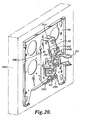
- device interface 36 generally includes inner carrier 246, upper guide structure 248, a pair of lower guide structures 250, outer carrier 252, and adjustment assembly 254.
- Inner carrier 246 as depicted in Fig. 24 generally includes back plane 256 with spaced-apart lateral flanges 258, 260, and spaced apart horizontal flanges 262, 264, projecting therefrom.
- Upper follower aperture 266 and lower follower aperture 268 are defined in lateral flange 258 in registry with corresponding upper and lower follower apertures 270, 272, defined in lateral flange 260.
- Each lateral flange 258, 260 defines a pair of facing shoulders 274, 276.
- Horizontal flange 262 defines aperture 278 while horizontal flange 264 defines aperture 280 in registry with aperture 278.
- attachment channels 60, 61 are positioned so as to overlap, with apertures 112 and 114 in registry.
- Bushing 116 is received through apertures 112 and bushing 118 is received through apertures 114.
- Bushings 116, 118 together define bore 120, which is disposed in registry with apertures 278, 280, in horizontal flanges 262, 264, of inner carrier 246.
- bolt 122 is received through apertures 278, 280, and bore 120, and is secured in place with a nut (not depicted).
- Attachment channel 60 is received between facing shoulders 274, 276, of lateral flanges 258, 260, with upper flange 100 confronting shoulder 274 and lower flange 102 confronting shoulder 276.
- inner carrier 246, and each of attachment channels 60, 61, and the upper arms 54 attached thereto are pivotable about bolt 122. Accordingly, a user may push or pull on device interface 36, which causes arms 52, 54, to pivot at sleeves 58, pivot 56 and at bolt 122.
- the articulating arrangement of arms 52, 54, and the pivotal connections of sleeves 58 with upright columns 44 of attachment channels 60, 61, with carrier 70 at bolt 122, enable the device interface and a display attached thereto to be selectively positioned laterally and inward and outward relative to the fixed structure 40.
- upper guide member 248 generally includes a pair of lateral walls 282, 284, connected by upper wall 286.
- Lateral wall 282 defines apertures 288, 290, in registry with apertures 292, 294, respectively, defined in lateral wall 284.
- Each lateral wall 282, 284, also defines a guide structure in the form of a slot 296, 298.
- Positioning tabs 300, 302 are defined at the bottom tips 304, 306, of each of lateral walls 282, 284, respectively.
- Lower guide member 250 as depicted in Fig. 26 , defines aperture 308, a guide structure in the form of slot 310 and a friction adjustment slot 312. Positioning notch 314 is defined at upper tip 316.
- Outer carrier 252 as depicted in Fig. 23 generally includes back portions 318, 320, with spaced-apart lateral flanges 322, 324, projecting therefrom.
- Upper pivot aperture 326 and lower pivot aperture 328 are defined in lateral flange 322 in registry with corresponding upper and lower pivot apertures 330, 332, defined in lateral flange 324.
- Back portions 318, 320 define apertures 334 for receiving fasteners (not depicted) to attach interface plate 78 on outer faces 336 of back portions 318, 320.
- Apertures 337 are defined at the upper tip 339 of each lateral flange 322, 324.
- Upper guide member 248 is pivotally coupled to outer carrier 252 between lateral flanges 322, 324, at pivots 338 which extend inward from the outer surface of lateral flanges 322 and 324, through upper pivot aperture 326 and aperture 290 and upper pivot aperture 330 and aperture 294, respectively.
- a lower guide member 250 is pivotally coupled on the inside face 340 of each lateral flange 322, 324, at pivots 342, which extend inward from the outer surface of lateral flanges 322 and 324, through lower pivot apertures 328 and into aperture 308.
- each lower guide member 250 is engaged with one of positioning tabs 300, 302, of upper guide member 248 as before so that as upper guide member 248 pivots, lower guide members 250 pivot in unison a corresponding distance in the opposite pivotal direction.
- Follower pins 344, 346 are received through apertures 266, 270, and 268, 272, of inner carrier 246, respectively.
- Inner carrier 246 is received between lateral flanges 282, 284 of upper guide member 248 and between lower guide members 250.
- Follower pin 344 presents opposing ends 348, 350, which are slidably or rollably engaged in guide structures 296, 298, of upper guide member 248 respectively.
- follower pin 346 presents opposing ends 352, 354, which are slidably or rollably engaged in guide structures 310 of the separate lower guide members 250.
- Adjustment assembly 254 generally includes carrier 356, adjustment screw 358, and pivot block 360.
- Carrier 356 generally includes an L-shaped body portion 362 with a pair of opposing lateral ears 364. Body portion 362 is pivotally coupled between lateral flanges 322, 324, of outer carrier 252 with pivots 366 extending through apertures 337 into ears 364. Adjustment screw 358 has threaded shaft portion 367 extending through front wall 368 of body portion 362. Retainer 369 and knob 370 on either side of front wall 368 retain and prevent translation of adjustment screw 358 relative to body portion 362.
- Pivot block 360 is pivotally coupled between lateral flanges 282, 284, of upper guide member 248 with pivots 372 extending through apertures 288 and 292 and into pivot block 360. Pivot block 360 further defines transverse threaded aperture 374 which receives threaded shaft portion 367 of adjustment screw 358.
- pivot block 360 In use, as adjustment screw 358 is tightened, pivot block 360 is drawn toward front wall 368, causing upper guide member 248 to pivot about pivots 338 in a clockwise direction when viewed from the vantage point of Figs. 27 and 28 . Due to the engagement of positioning tabs 300, 302, in positioning notches 312, lower guide members 250 are simultaneously pivoted counterclockwise about pivots 342 when viewed from the vantage point of Figs. 27 and 28 . As a result of the pivoting motion of upper guide member 248 and lower guide members 250, the orientation of slots 296, 298, and 310 is altered so as to define new arcs 242 having a relatively larger radius R. Tilt Axis B-B is moved away from interface plate 78, so that distance D is relatively larger.
- pivot block 360 is urged away from front wall 368, causing upper guide member 248 to pivot about pivots 338 in a counterclockwise direction when viewed from the vantage point of Figs. 27 and 28 .
- the orientation of slots 296, 298, and 310 is altered so as to define new arcs 242 having a relatively smaller radius R.
- Tilt Axis B-B is toward from interface plate 78, so that distance D is relatively smaller.
- a display 240 or other device coupled to interface plate 78 may be tilted about tilt axis B-B, for example by pushing or pulling the top or bottom edge of the display 240.
- Follower pins 344, 346, will slide or roll in slots 296, 298 and 310, and outer carrier 252, upper guide member 248, lower guide members 250, interface plate 78 and the attached electronic display 240 will rotate about tilt axis B-B.
Claims (14)
- Système de montage pour un dispositif d'affichage électronique (240), le système comprenant :une structure de support (32) conçue pour être attachée à une structure fixe (40) ; etune interface d'affichage (36) couplée de façon opérationnelle à la structure de support (32), l'interface d'affichage (36) comprenant :un organe d'interface présentant une surface de montage d'affichage (78) destinée à recevoir l'affichage électronique (240) ; etun ensemble formant tête basculante (70, 72, 74, 76) définissant un axe de basculement sensiblement horizontal (B-B) orienté généralement parallèlement à la surface de montage d'affichage (78) et espacé par rapport à celle-ci de telle manière que lorsque le dispositif d'affichage électronique (240) est reçu sur la surface de montage d'affichage (78), l'axe de basculement (B-B) s'étend à travers le dispositif d'affichage électronique (240), caractérisé en ce que l'ensemble formant tête basculante comprend un mécanisme de commande (166) pour décaler sélectivement l'axe de basculement (B-B) entre un premier emplacement espacé d'une première distance (D2) de la surface de montage d'affichage (78) et un second emplacement espacé d'une seconde distance (D3) de la surface de montage d'affichage (78), la seconde distance (D3) étant supérieure à la première distance (D2).
- Système selon la revendication 1, dans lequel l'ensemble formant tête basculante comprend :un premier support (70, 76) comprenant au moins un suiveur (230); etun premier organe de guidage (72) définissant une première structure de guidage (142, 148) positionnée le long d'un arc centré sur l'axe de basculement (B-B), dans lequel l'au moins un suiveur (230) et la première structure de guidage (142, 148) sont en prise et définissent ensemble une plage de mouvement de basculement autour de l'axe de basculement (B-B), et dans lequel le mécanisme de commande (166) est couplé de façon opérationnelle au premier organe de guidage (72) pour décaler sélectivement une orientation de la première structure de guidage (142, 148) afin d'effectuer le décalage sélectif de l'axe de basculement (B-B) entre les premier et second emplacements.
- Système selon la revendication 2, dans lequel la première structure de guidage (142, 148) est incurvée.
- Système selon la revendication 2, dans lequel la première structure de guidage (142, 148) est généralement rectiligne.
- Système selon la revendication 2, dans lequel la première structure de guidage (142, 148) est angulaire.
- Système selon la revendication 2, dans lequel la première structure de guidage (142, 148) est une fente.
- Système selon la revendication 2, comprenant en outre un second organe de guidage (74) définissant une seconde structure de guidage (184, 186) positionnée le long d'un arc centré sur l'axe de basculement (B-B), dans lequel le premier support (70, 76) comprend au moins une paire de suiveurs (230, 234), et dans lequel l'un de la paire de suiveurs (230, 234) est en prise avec la première structure de guidage (184, 186) et l'autre de la paire de suiveurs (234, 230) est en prise avec la seconde structure de guidage (184, 186).
- Système selon la revendication 7, dans lequel les premier et seconde organes de guidage (70, 74) sont couplés de façon opérationnelle de telle sorte que lorsque l'orientation de la première structure de guidage (76) est décalée avec le mécanisme de commande (166), une orientation du second organe de guidage (74) est également décalée.
- Système selon la revendication 7, dans lequel les premier et seconde organes de guidage (70, 74) sont couplés de façon opérationnelle de telle sorte que lorsque l'orientation de la première structure de guidage (76) est décalée avec le mécanisme de commande (166), une orientation du second organe de guidage (74) reste fixe.
- Système selon la revendication 2, dans lequel le suiveur est un axe.
- Système selon la revendication 1, comprenant en outre un dispositif d'affichage électronique (240).
- Système selon la revendication 1, dans lequel la structure de support (32) comprend au moins un bras (46, 48).
- Système selon la revendication 12, dans lequel l'au moins un bras (46, 48) est articulé.
- Système selon la revendication 1, dans lequel la structure de support (32) comprend un mécanisme d'ajustement de la hauteur (50) pour ajuster la hauteur de l'interface d'affichage (36).
Applications Claiming Priority (2)
| Application Number | Priority Date | Filing Date | Title |
|---|---|---|---|
| US88330307P | 2007-01-03 | 2007-01-03 | |
| PCT/US2008/000044 WO2008083396A1 (fr) | 2007-01-03 | 2008-01-03 | Monture de dispositif ayant un axe de basculement pouvant être sélectivement positionné |
Publications (3)
| Publication Number | Publication Date |
|---|---|
| EP2108180A1 EP2108180A1 (fr) | 2009-10-14 |
| EP2108180A4 EP2108180A4 (fr) | 2011-05-04 |
| EP2108180B1 true EP2108180B1 (fr) | 2013-07-17 |
Family
ID=39589014
Family Applications (1)
| Application Number | Title | Priority Date | Filing Date |
|---|---|---|---|
| EP08705455.7A Active EP2108180B1 (fr) | 2007-01-03 | 2008-01-03 | Monture de dispositif ayant un axe de basculement pouvant etre selectivement positionne |
Country Status (5)
| Country | Link |
|---|---|
| US (1) | US8072739B2 (fr) |
| EP (1) | EP2108180B1 (fr) |
| CN (1) | CN101720482B (fr) |
| CA (1) | CA2674471C (fr) |
| WO (1) | WO2008083396A1 (fr) |
Families Citing this family (40)
| Publication number | Priority date | Publication date | Assignee | Title |
|---|---|---|---|---|
| CN101543063B (zh) | 2007-01-05 | 2012-06-20 | Csav股份有限公司 | 用于对平板电子显示器进行倾斜定位的避墙式自平衡安装座 |
| PL384694A1 (pl) * | 2008-03-14 | 2009-09-28 | Furniture In Motion, Inc. | Głowica ekranu wyświetlającego, zwłaszcza płaskiego ekranu telewizyjnego |
| US8675354B2 (en) * | 2007-06-27 | 2014-03-18 | Voxx International Corporation | Multi-media memo board |
| TW201030266A (en) * | 2009-01-05 | 2010-08-16 | Peerless Ind Inc | Multiple arm articulating mounting system |
| TW201030265A (en) | 2009-01-05 | 2010-08-16 | Peerless Ind Inc | Low profile articulating mounting system |
| TW201028585A (en) | 2009-01-05 | 2010-08-01 | Peerless Ind Inc | Moveable mounting system |
| WO2010080925A1 (fr) | 2009-01-07 | 2010-07-15 | Milestone Av Technologies Llc | Socle d'afficheur avec axe d'inclinaison à position réglable |
| US9441784B2 (en) * | 2010-02-22 | 2016-09-13 | 3D Space Arms Pty Ltd | Support mechanism |
| US10281080B1 (en) | 2010-06-04 | 2019-05-07 | Kurt William Massey | Adjustable mounting systems for televisions |
| US8724037B1 (en) | 2010-06-04 | 2014-05-13 | Kurt William Massey | Mounting system |
| US9625091B1 (en) | 2014-12-06 | 2017-04-18 | Kurt William Massey | Adjustable mounting systems for televisions |
| US8864092B2 (en) * | 2010-08-04 | 2014-10-21 | Brian Newville | Television mount assembly |
| US20130314890A1 (en) | 2010-11-30 | 2013-11-28 | Milestone Av Technologies Llc | Electronic display mount with extreme tilt feature |
| AU2015224380B2 (en) * | 2011-02-22 | 2017-02-02 | 3D Space Arms Pty Ltd | A Support Mechanism |
| US9062816B2 (en) | 2012-01-06 | 2015-06-23 | Wirepath Home Systems, Llc | Tilt head assemblies and methods of using the same |
| US9475525B2 (en) * | 2012-04-09 | 2016-10-25 | Illinois Tool Works Inc. | Arcuate clip assembly |
| US9052057B2 (en) | 2012-10-02 | 2015-06-09 | Mw Products Llc | Flexible mount apparatus and system |
| CN102887382B (zh) * | 2012-10-19 | 2016-01-20 | 江苏高博智融科技有限公司 | 一种推料板 |
| CN104885447B (zh) * | 2012-11-05 | 2018-07-31 | 里程碑影音技术有限责任公司 | 具有微调结构的短焦投影机支架 |
| US9383060B2 (en) * | 2012-12-06 | 2016-07-05 | Synergy Global Supply, Inc. | Security wall rack and television mount combination |
| EP3406958B1 (fr) | 2013-01-07 | 2019-12-04 | Samsung Electronics Co., Ltd. | Dispositif de charnière et appareil d'affichage avec un dispositif de charnière à l'aide d'une position de coulissement |
| US9765923B2 (en) * | 2013-10-09 | 2017-09-19 | Milestone Av Technologies Llc | Cleat mount with visual and audible indicator |
| USD743969S1 (en) | 2013-10-16 | 2015-11-24 | Wirepath Home Systems, Llc | Single arm articulating mount for an electronic display |
| USD747724S1 (en) | 2013-12-20 | 2016-01-19 | Wirepath Home Systems, Llc | Dual arm articulating mount for an electronic display |
| US9699924B2 (en) * | 2014-08-26 | 2017-07-04 | Milestone Av Technologies Llc | Display mount leveler |
| AU2016297775B2 (en) | 2015-07-24 | 2021-04-08 | Zipwall Llc | Partition mount system including head coupler with adjustable head length and head position |
| AU2016381274B2 (en) | 2015-12-28 | 2022-09-08 | Zipwall, Llc | Self-closing entryway partition |
| US10154729B2 (en) | 2016-05-10 | 2018-12-18 | Knape & Vogt Manufacturing Company | Articulating ergonomic support arm |
| US10738941B2 (en) | 2017-09-04 | 2020-08-11 | Manehu Product Alliance, Llc | Display mount assembly |
| CN112165886B (zh) | 2018-03-02 | 2022-08-23 | 爱格升公司 | 高度可调整平台和相关联机构 |
| WO2019169346A1 (fr) | 2018-03-02 | 2019-09-06 | Ergotron, Inc. | Plates-formes réglables en hauteur et mécanismes associés |
| US10859201B2 (en) | 2018-04-10 | 2020-12-08 | Manehu Product Alliance, Llc | Display mount assembly |
| CN110388548B (zh) * | 2018-04-19 | 2022-04-22 | 鸿富锦精密电子(重庆)有限公司 | 显示装置 |
| USD1002351S1 (en) | 2019-04-25 | 2023-10-24 | Legrand Av Inc. | Tapered articulating arm assembly for wall-mounted display mount |
| US11215313B1 (en) * | 2019-05-24 | 2022-01-04 | Snap One, Llc | Display mounts and related systems and methods |
| CA3146417A1 (fr) | 2019-07-10 | 2021-01-14 | Ergotron, Inc. | Systeme et procede de montage de dispositif d'affichage |
| US11033107B2 (en) | 2019-07-16 | 2021-06-15 | Francis Douglas Warren | Tilting mounting apparatus |
| WO2021127552A1 (fr) | 2019-12-19 | 2021-06-24 | Manehu Product Alliance, Llc, D/B/A | Système de montage réglable pour dispositif d'affichage |
| CN115398139A (zh) | 2020-02-10 | 2022-11-25 | 显示器产品联盟Dba曼特尔蒙特有限责任公司 | 多方向显示器安装件 |
| CN117337367A (zh) | 2021-05-12 | 2024-01-02 | 科尔布鲁克博松及桑德斯(产品)有限公司 | 用于高负载显示器支撑系统的倾斜头部 |
Family Cites Families (204)
| Publication number | Priority date | Publication date | Assignee | Title |
|---|---|---|---|---|
| US2734708A (en) | 1956-02-14 | Mounting of antenna masts | ||
| US1320775A (en) | 1919-11-04 | Lamp-stjppobt | ||
| US153943A (en) | 1874-08-11 | Improvement in brackets for dentists chairs | ||
| US212618A (en) | 1879-02-25 | Improvement in doors for stoves | ||
| US257050A (en) | 1882-04-25 | La mp-bracket | ||
| US1282489A (en) | 1916-02-08 | 1918-10-22 | Frank A Strodel | Drawing-board holder. |
| US1358159A (en) | 1920-03-09 | 1920-11-09 | Kern John | Reflector-mounting |
| US1574277A (en) | 1924-10-14 | 1926-02-23 | Henry M Groue | Rim and tire construction for vehicle wheels |
| US1646379A (en) | 1924-12-22 | 1927-10-18 | Kales Stamping Company | Mirror support |
| US1628218A (en) | 1926-02-09 | 1927-05-10 | Dora F Beauchamp | Adjustable reflector |
| US1977153A (en) | 1928-05-23 | 1934-10-16 | Remac Patents Corp | Mount for moving picture cameras |
| US2030889A (en) | 1933-04-01 | 1936-02-18 | Sidney H Negrotto | Mount for machine guns |
| US2233882A (en) | 1938-01-24 | 1941-03-04 | Bobek William | Self-locking concealed hinge |
| US2466219A (en) | 1944-03-31 | 1949-04-05 | Sydney T Farrell | Gun mount |
| US2525534A (en) * | 1947-11-05 | 1950-10-10 | Eastman Kodak Co | Elevating mechanism |
| US2967035A (en) | 1957-09-23 | 1961-01-03 | Elizabeth W Simons | Hinge mounting for mirrors and the like |
| US3182946A (en) | 1963-01-23 | 1965-05-11 | Dudko Nicholas | Swing-away can opener |
| US3206153A (en) | 1963-02-25 | 1965-09-14 | Bjorgensen Designs Ltd | Tilt swivel mechanism for chairs |
| US3574340A (en) | 1969-02-27 | 1971-04-13 | Kenneth A Busche | Television receiver adjustable tilt suspension |
| GB1280913A (en) | 1970-07-06 | 1972-07-12 | Rank Organisation Ltd | Motion picture camera mounts |
| US4068961A (en) | 1976-08-23 | 1978-01-17 | Milgo Electronic Corporation | Swivel joint |
| US4238802A (en) | 1978-12-18 | 1980-12-09 | General Dynamics Corporation, Pomona Division | Differential drive rolling arc gimbal |
| IT1128801B (it) | 1980-06-05 | 1986-06-04 | Olivetti & Co Spa | Dispositivo per orientare un apparecchiatura video rispetto ad una struttura fissa |
| GB2096234B (en) | 1981-04-03 | 1985-02-20 | Mouldmaking Design Centre Ltd | Swivel mounting |
| GB2115479B (en) | 1982-02-26 | 1985-10-02 | Plessey Co Plc | Supporting assembly |
| DE3215379A1 (de) | 1982-04-24 | 1983-10-27 | Plaubel, Feinmechanik & Optik GmbH, 6000 Frankfurt | Fotografische mattscheibenkamera |
| US4483803A (en) | 1982-09-30 | 1984-11-20 | The Halcon Sd Group, Inc. | Preparation of carboxylic acid anhydrides |
| US4687305A (en) | 1984-05-29 | 1987-08-18 | Spy-Mirrors, Inc. | Mirror mounting apparatus |
| US4562988A (en) * | 1984-06-27 | 1986-01-07 | Northern Telecom Limited | Video display mounting mechanism providing pivoting and tilting of the display |
| US4880191A (en) | 1984-07-05 | 1989-11-14 | Unisys Corporation | Mounting arrangement for display terminal |
| US4652890A (en) | 1984-07-24 | 1987-03-24 | Crean Robert F | High rigidity, low center of gravity polar mount for dish type antenna |
| US4621782A (en) | 1984-07-26 | 1986-11-11 | At&T Bell Laboratories | Arrangement for mounting apparatus |
| US4645153A (en) | 1985-05-23 | 1987-02-24 | Ncr Corporation | Tilt and swivel support |
| DE8530047U1 (de) | 1985-10-23 | 1986-05-15 | Ncr Corp., Dayton, Ohio | Ausziehbarer, höhenverstellbarer Schwenkarm für Bildschirmgeräte od. dgl. |
| US4762378A (en) | 1986-03-17 | 1988-08-09 | Sanyo Electric Co., Ltd. | Display apparatus |
| US4718317A (en) | 1986-08-21 | 1988-01-12 | Roy F. Hensler | Hose coupling wrench |
| US4768744A (en) | 1986-08-27 | 1988-09-06 | Richard Leeds | Apparatus for supporting a load in a dynamically balanced condition |
| US4844387A (en) | 1986-12-31 | 1989-07-04 | Hunt Holdings, Inc. | Monitor arm apparatus |
| US4836486A (en) | 1987-04-16 | 1989-06-06 | Anthro Corporation | Adjustable support |
| US4814759A (en) | 1987-07-08 | 1989-03-21 | Clinicom Incorporated | Flat panel display monitor apparatus |
| US4836478A (en) | 1987-10-15 | 1989-06-06 | Ergotron, Inc. | Suspension system for personal computers and monitors |
| US4934645A (en) | 1989-03-20 | 1990-06-19 | Rtc Industries, Inc. | Shelving assembly |
| US4989813A (en) | 1989-11-29 | 1991-02-05 | Samsung Electron Devices Co., Ltd. | Supporting base for controlling height, swivel and inclination of display means |
| KR930000305Y1 (ko) | 1989-11-30 | 1993-01-25 | 현대전자산업 주식회사 | 모니터의 회전 및 경사 각도 조절장치 |
| US5037050A (en) | 1990-03-28 | 1991-08-06 | Digital Equipment Corporation | Interlocking assembly for adjustable mounting of a display unit |
| US5040759A (en) | 1990-07-05 | 1991-08-20 | Wainwright Andrew G | Camera mount for taking panoramic pictures |
| JP2500239Y2 (ja) | 1990-10-02 | 1996-06-05 | 矢崎総業株式会社 | コネクタの固定構造 |
| JP2708638B2 (ja) | 1991-02-18 | 1998-02-04 | 三菱電機株式会社 | 回転架台 |
| US5102081A (en) | 1991-03-15 | 1992-04-07 | Barchus David D | Telescopable pivotal mounting assembly |
| GB2253992A (en) | 1991-03-23 | 1992-09-30 | Ibm | A mounting bracket |
| US5139223A (en) | 1991-04-09 | 1992-08-18 | Marty Sedighzadeh | Wall/ceiling support for television monitor |
| US5305114A (en) | 1991-07-12 | 1994-04-19 | Matsushita Electric Industrial Co., Ltd. | Electronic blackboard apparatus |
| US5165644A (en) | 1991-07-25 | 1992-11-24 | Thomas Allen | Mounting apparatus for a video display |
| EP0619892A4 (en) | 1992-01-03 | 1996-10-02 | Kenneth A Haines | Methods of hologram constructions using computer-processed objects. |
| US5582375A (en) | 1992-04-20 | 1996-12-10 | Martin; Michael | Adjustable ergonomic support for computer keyboards |
| GB2271273B (en) | 1992-10-10 | 1997-03-05 | Haropa Prod Ltd | Support apparatus |
| US5277392A (en) | 1992-10-19 | 1994-01-11 | Curtis Manufacturing Company, Inc. | Adjustable computer monitor arm and method |
| AU119523S (en) | 1993-03-17 | 1994-03-01 | Toshiba Kk | An electronic computer |
| US5520361A (en) | 1993-04-20 | 1996-05-28 | Inkel Corporation | Monitor tilting device |
| DK45493D0 (da) | 1993-04-21 | 1993-04-21 | Vm Acoustics Aps | Indstilleligt ophaengningsbeslag til vaegmontering f.eks. for hoejttalere |
| JP2654750B2 (ja) | 1993-10-28 | 1997-09-17 | 日本コントロール工業株式会社 | 揺動機台 |
| USD361068S (en) | 1994-04-25 | 1995-08-08 | Pacific Monolithics, Inc. | Adjustable-angle antenna-mounting bracket assembly |
| US5465557A (en) | 1994-06-09 | 1995-11-14 | Koch Supplies, Inc. | Hinge assembly for vacuum packaging machine |
| US5632463A (en) | 1994-06-13 | 1997-05-27 | Samsung Electronics Co., Ltd. | Monitor stand assembly |
| KR960014142B1 (ko) | 1994-08-06 | 1996-10-14 | 엘지전자 주식회사 | 영상표시기의 각도조절장치 |
| US5553820A (en) | 1994-10-17 | 1996-09-10 | Rubbermaid Office Products Inc. | Adjustable monitor arm |
| KR0124727Y1 (ko) | 1995-01-16 | 1998-09-15 | 구자홍 | 모니터에 사용되는 스피커 일체형 받침대 구조 |
| US5876008A (en) | 1995-01-17 | 1999-03-02 | Ergotron, Inc. | Suspension system for video monitor or other equipment |
| NL9500300A (nl) | 1995-02-17 | 1996-10-01 | Vogel S Holding Bv | Samenstel geschikt voor het ondersteunen van een elektronisch apparaat alsmede koppelstuk. |
| GB9503728D0 (en) | 1995-02-24 | 1995-04-12 | Commercial Brians Limited | Improvements in and relating to support brackets |
| US5713549A (en) | 1995-05-22 | 1998-02-03 | Shieh; En-Ru | Monitor support device |
| US5603478A (en) | 1995-08-14 | 1997-02-18 | Wang; Daniel | Keyboard support |
| US5634622A (en) | 1995-09-18 | 1997-06-03 | Pye; Craig D. | Remote controllable television viewing stand |
| US5584735A (en) | 1996-01-24 | 1996-12-17 | Mcmath; John W. | Warm water supply system |
| US5730408A (en) | 1996-02-28 | 1998-03-24 | Knoll, Inc. | Independently adjustable mouse pad and keyboard support apparatus |
| US5743503A (en) | 1996-03-08 | 1998-04-28 | Ergotron, Inc. | Computer suspension system |
| USD415768S (en) | 1996-04-10 | 1999-10-26 | Howell Richard J | Holder for flat screen monitors |
| US5687939A (en) | 1996-04-26 | 1997-11-18 | Moscovitch; Jerry | Dual display system |
| US5751548A (en) | 1996-05-13 | 1998-05-12 | International Business Machines Corporation | Docking station for a portable computer providing rotational movement of the computer's viewable screen in three different planes |
| ES1034279U (es) | 1996-05-30 | 1996-12-16 | Telefonica Nacional Espana Co | Soporte poliposicionable para monitores de television. |
| US5842672A (en) | 1996-06-07 | 1998-12-01 | Ergotron, Inc. | Mounting system for flat panel display, keyboard and stand |
| US5923852A (en) | 1996-09-04 | 1999-07-13 | Advanced Micro Devices, Inc. | Method and system for fast data transmissions in a processing system utilizing interrupts |
| US6048013A (en) | 1996-10-07 | 2000-04-11 | Phd, Inc. | Modular stamped parts transfer gripper |
| TW327460U (en) | 1996-11-16 | 1998-02-21 | Adi Corp | Liquid crystal display capable of leaning forward and backward |
| DE29710833U1 (de) | 1996-11-16 | 1997-08-28 | Adi Corp Tai Ping Shiang | LCD-Tragekonstruktion |
| US6068227A (en) | 1997-03-11 | 2000-05-30 | Pixelvision Technology, Inc. | Flat panel display housing |
| USD395892S (en) | 1997-05-01 | 1998-07-07 | Allen Solomon | Universal speaker mounting device |
| TW321414U (en) | 1997-05-07 | 1997-11-21 | Amtran Technology Co Ltd | Pivot-rotation device of flat-display panel |
| KR100255765B1 (ko) | 1997-07-09 | 2000-05-01 | 구자홍 | 영상표시기기의 전후 조절 받침대 구조 |
| JP3043710B2 (ja) | 1997-08-04 | 2000-05-22 | キヤノン株式会社 | パネルを支持する支持構造、およびパネルと該パネルを支持する支持構造を有するパネル装置、および該パネル装置を用いた画像形成装置 |
| TW378830U (en) | 1997-08-09 | 2000-01-01 | Mitac Int Corp | Sliding and revolving structure for LCD screens |
| US6042068A (en) | 1997-09-04 | 2000-03-28 | Peerless Indsutries, Inc. | Low profile LCD projector mount |
| US5768648A (en) | 1997-09-05 | 1998-06-16 | Roy Isaia | Camera mount for controlled and steady rolling movement |
| US6113047A (en) | 1997-12-15 | 2000-09-05 | Intermec Technologies Corporation | Dual point vehicle mount for computer terminal |
| IL123261A (en) | 1998-02-11 | 2000-12-06 | Barkan Lior | Support tray tilt mechanism |
| US6012693A (en) | 1998-02-19 | 2000-01-11 | Ergotron, Inc. | Multi-function display mounting system |
| JPH11274966A (ja) | 1998-03-19 | 1999-10-08 | Toshiba Corp | 携帯無線端末装置 |
| US6036337A (en) | 1998-05-22 | 2000-03-14 | Belfer; Bruce D. | Virtual axis lighting fixture |
| DE29809300U1 (de) | 1998-05-22 | 1998-08-06 | Seisler & Co | Anordnung eines Spiegels |
| US6213821B1 (en) | 1998-09-30 | 2001-04-10 | Johnson Outdoors Inc | Trolling motor assembly |
| WO2000003373A1 (fr) | 1998-07-09 | 2000-01-20 | Mitsubishi Denki Kabushiki Kaisha | Visuel plat et pieces de fixation pour dispositif de visualisation |
| US6045103A (en) | 1998-07-17 | 2000-04-04 | Lucent Technologies, Inc. | Multiple axis bracket with keyed mount |
| US6264152B1 (en) | 1998-07-17 | 2001-07-24 | Lucent Technologies Inc. | Multiple access mounting bracket |
| US6125030A (en) | 1998-08-07 | 2000-09-26 | Lear Donnelly Overhead Systems L.L.C. | Vehicle overhead console with flip down navigation unit |
| US6565055B1 (en) | 1998-10-14 | 2003-05-20 | Work-Rite Ergonomic Accessories, Inc. | Tilt adjustable keyboard support |
| US6409127B1 (en) | 1998-10-27 | 2002-06-25 | Knape & Vogt Manufacturing Co. | Adjustable keyboard support mechanism |
| US6663064B1 (en) | 1999-12-01 | 2003-12-16 | Garmin Corporation | Multi-position articulating mounting apparatus for an electronic device |
| US6126128A (en) | 1998-11-20 | 2000-10-03 | Lucent Technologies Inc. | Adjustable mounting bracket |
| JP3538046B2 (ja) | 1998-12-11 | 2004-06-14 | Nec液晶テクノロジー株式会社 | 携帯用端末装置 |
| JP3632949B2 (ja) * | 1999-01-25 | 2005-03-30 | 東芝テック株式会社 | 表示装置のチルト機構 |
| JP2000252643A (ja) | 1999-02-26 | 2000-09-14 | Kato Electrical Mach Co Ltd | チルトヒンジ |
| USD440863S1 (en) | 1999-03-13 | 2001-04-24 | Avf Group Limited | Bracket, principally for supporting a television set |
| CN1183310C (zh) | 1999-04-14 | 2005-01-05 | 索斯科公司 | 月牙形铰链 |
| US6102348A (en) | 1999-04-19 | 2000-08-15 | Lucasey Manufacturing Company | Appliance mounting device |
| US6244552B1 (en) | 1999-04-21 | 2001-06-12 | Force 10 Marine Ltd. | Mounting bracket for maintaining an article level |
| US6138970A (en) | 1999-05-07 | 2000-10-31 | Sohrt; Thomas M. | Universally adjustable mounting system |
| US6409134B1 (en) | 1999-06-07 | 2002-06-25 | Innovative Office Products, Inc. | Arm apparatus for mounting electronic devices with cable management system |
| DK199900212U3 (da) | 1999-05-26 | 1999-10-22 | Soeren Rasmussen | Motoriseret rotations- og justerings anordning for f.eks. monitorer |
| US6505988B1 (en) | 1999-06-02 | 2003-01-14 | Innovative Office Products, Inc. | Tilter for positioning electronic devices |
| US6189842B1 (en) | 1999-06-21 | 2001-02-20 | Palo Alto Design Group | Tilt and swivel adjustment of flat panel display having detents for landscape and portrait positions and kickout for preventing contact between flat panel display and base |
| JP4460085B2 (ja) | 1999-07-06 | 2010-05-12 | 出光興産株式会社 | 二酸化炭素冷媒用冷凍機油組成物 |
| US6273383B1 (en) | 1999-09-27 | 2001-08-14 | Innovative Office Products, Inc. | Arm apparatus for mounting electronic devices, and method of making and using the same |
| US6273382B1 (en) | 1999-09-30 | 2001-08-14 | Gregory L. Pemberton | Adjustable tilt-down keyboard support device |
| US6354549B2 (en) | 1999-11-02 | 2002-03-12 | Ergotron, Inc. | Ratcheted pivot |
| JP2001142408A (ja) * | 1999-11-17 | 2001-05-25 | Hitachi Ltd | 画像表示装置 |
| WO2001035796A1 (fr) | 1999-11-18 | 2001-05-25 | Claiteal Pty Ltd | Bras support pour terminal a ecran de visualisation |
| US6213438B1 (en) | 1999-12-16 | 2001-04-10 | Ostby Leroy M. | Computer support for vehicle use having multiple position adjustments |
| JP2001175188A (ja) | 1999-12-20 | 2001-06-29 | Fujitsu General Ltd | 表示装置の据付装置 |
| US6510049B2 (en) | 2000-01-06 | 2003-01-21 | Rosen Products Llc | Adjustable display monitor unit |
| US6654235B2 (en) | 2000-01-25 | 2003-11-25 | Bruce Imsand | Portable workstation computer |
| GB2360894B (en) | 2000-03-30 | 2004-11-10 | Peter Thomas Bosson | Display device support system |
| US6530546B1 (en) | 2000-04-25 | 2003-03-11 | Omnimount Systems, Inc. | Cable mount |
| US6347776B1 (en) | 2000-06-30 | 2002-02-19 | Po-An Chuang | Multi-directional mounting bracket |
| US6361012B1 (en) | 2000-07-06 | 2002-03-26 | Punch Video Inc. | Television stand for a vehicle |
| US6367756B1 (en) | 2000-07-07 | 2002-04-09 | James Wang | Adjustable device support and anchor means arrangement |
| US6585203B1 (en) | 2000-07-17 | 2003-07-01 | Agilent Technologies, Inc. | Flat panel display exterior rack mount |
| US6340146B1 (en) | 2000-07-28 | 2002-01-22 | Proton Electronic Industrial Co., Ltd. | Ceiling LCD mounting structure |
| US6418010B1 (en) | 2000-08-11 | 2002-07-09 | Gateway, Inc. | Convertible flat panel display hanging support |
| TW478700U (en) | 2000-09-20 | 2002-03-01 | Benq Corp | Wall-hanging type stand for plasma TV |
| US6378830B1 (en) | 2000-10-05 | 2002-04-30 | Lu Sheng-Nan | Adjustable support for an LCD monitor |
| DE20018361U1 (de) | 2000-10-26 | 2001-04-05 | Hung Ray | Haltevorrichtung für ein Flüssig-Kristallbildschirm |
| EP1343997A1 (fr) | 2000-11-21 | 2003-09-17 | Eyegonomic Aps | Support pour unite d'interface, telle qu'un ecran ou un clavier d'ordinateur, et bras pour ladite unite |
| TW487277U (en) | 2000-12-01 | 2002-05-11 | Acer Inc | Flat-panel display device and mounting device thereof |
| USD460078S1 (en) | 2000-12-18 | 2002-07-09 | Chin-Chu Li | Supporting frame |
| JP3078557U (ja) | 2000-12-25 | 2001-07-10 | 株式会社寺岡精工 | タッチパネルの支持構造 |
| US6484987B2 (en) | 2000-12-29 | 2002-11-26 | Bellsouth Intellectual Property Corporation | Mounting bracket |
| US6487274B2 (en) | 2001-01-29 | 2002-11-26 | Siemens Medical Solutions Usa, Inc. | X-ray target assembly and radiation therapy systems and methods |
| KR100703160B1 (ko) | 2001-02-19 | 2007-04-05 | 삼성전자주식회사 | 디스플레이장치 |
| US6416027B1 (en) | 2001-02-28 | 2002-07-09 | James K. Hart | Apparatus for retracting a television to a stored position and extending the television to a viewing position |
| FR2821902B1 (fr) | 2001-03-12 | 2003-06-27 | Id Ind & Design | Dispositif de support pour un ecran plat a cristaux liquide |
| US6560094B2 (en) | 2001-03-21 | 2003-05-06 | Acme Portable Machines Gmbh | Mounting device for a monitor, a flat monitor with such a mounting device, and an assembly of a flat monitor, a drawer and a computer |
| US6402109B1 (en) | 2001-05-16 | 2002-06-11 | Chief Manufacturing, Inc. | Self-balancing mounting system for a flat panel display |
| US6671928B2 (en) | 2001-05-23 | 2004-01-06 | Kuo-Cheng Huang | Hinge assembly for monitor |
| KR100406487B1 (ko) | 2001-06-05 | 2003-11-17 | 엘지전자 주식회사 | 벽걸이용 디스플레이 장치의 고정 및 각도 조절장치 |
| KR100377629B1 (ko) | 2001-06-05 | 2003-03-26 | 엘지전자 주식회사 | 벽걸이용 디스플레이 장치의 각도 조절장치 |
| US20020190180A1 (en) | 2001-06-15 | 2002-12-19 | Cotterill Michael John | Linkage mechanism |
| TW512902U (en) | 2001-08-28 | 2002-12-01 | Chin-Chih Lin | Axial urging mechanism |
| TW564984U (en) | 2001-08-30 | 2003-12-01 | Hannstar Display Corp | Liquid crystal display with a ball-and-socket joint |
| US6478275B1 (en) | 2001-08-31 | 2002-11-12 | Min Hwa Huang | Support device for monitor, displayer or other object |
| US20030075653A1 (en) | 2001-10-19 | 2003-04-24 | Chin-Chu Li | Liquid crystal display support |
| US6454234B1 (en) | 2001-11-14 | 2002-09-24 | Charles Westbrook | Apparatus for supporting and restraining electronic viewing monitors without penetrating fasteners |
| CN1217304C (zh) | 2001-12-13 | 2005-08-31 | 株式会社村上开明堂 | 用于调整显示器高度的装置 |
| AU2002222629A1 (en) | 2001-12-13 | 2003-06-23 | Murakami Corporation | Direction regulator of display |
| TW540981U (en) | 2001-12-20 | 2003-07-01 | Mitac Int Corp | Display disposition device |
| NL1019821C2 (nl) | 2002-01-23 | 2003-07-30 | Vogel S Holding Bv | Inrichting voor het kantelbaar bevestigen van een beeldscherm aan een wand. |
| US6851226B2 (en) | 2002-02-15 | 2005-02-08 | Steelcase Development Corporation | Partition panel with modular appliance mounting arrangement |
| US6575419B1 (en) | 2002-03-12 | 2003-06-10 | Sun Microsystems, Inc. | Universal support system for displays |
| USD477606S1 (en) | 2002-04-24 | 2003-07-22 | Ergotron, Inc. | Support for flat panel monitor display unit |
| WO2003092341A2 (fr) | 2002-04-24 | 2003-11-06 | Innovative Office Products, Inc. | Support de reorientation de dispositifs electroniques multiples |
| US6923413B2 (en) | 2002-04-26 | 2005-08-02 | Premier Mounts | Mounting device for a flat screen display panel |
| AUPS285202A0 (en) | 2002-06-07 | 2002-06-27 | Claiteal Pty Ltd | Stand for flat panel display |
| KR100461185B1 (ko) | 2002-06-07 | 2004-12-13 | 삼성전자주식회사 | 모니터장치 |
| US6604722B1 (en) | 2002-06-10 | 2003-08-12 | Seng-Ling Tan | Display support |
| US6905101B1 (en) | 2002-06-11 | 2005-06-14 | Chief Manufacturing Inc. | Adjustable, self-balancing flat panel display mounting system |
| US6695270B1 (en) | 2002-08-15 | 2004-02-24 | Ole Falk Smed | Flat panel display system |
| US6592090B1 (en) | 2002-08-23 | 2003-07-15 | Chin-Chu Li | Object supporting structure |
| US6672553B1 (en) | 2002-08-26 | 2004-01-06 | Chin-Chih Lin | Suspension arm |
| US7152836B2 (en) | 2003-01-09 | 2006-12-26 | Csav, Inc. | Adjustable tilt mount |
| DK1590595T3 (da) | 2003-02-03 | 2007-05-07 | Bang & Olufsen As | Hældningsmekanisme |
| JP4167506B2 (ja) | 2003-02-03 | 2008-10-15 | 株式会社村上開明堂 | ディスプレイの方向調整装置 |
| US20040211870A1 (en) | 2003-04-11 | 2004-10-28 | Jeff Bremmon | Universal mount bracket |
| US20040232298A1 (en) | 2003-04-11 | 2004-11-25 | Jeff Bremmon | Flat panel display mounting system |
| US20040232301A1 (en) | 2003-04-11 | 2004-11-25 | Jeff Bremmon | Adaptable mounting system for flat panel display |
| US7028961B1 (en) | 2003-05-30 | 2006-04-18 | Csav, Inc. | Self-balancing adjustable flat panel mounting system |
| US7380760B2 (en) | 2003-05-30 | 2008-06-03 | Csav, Inc. | Self-balancing adjustable mounting system with friction adjustment |
| US7317611B2 (en) | 2003-07-23 | 2008-01-08 | Chief Manufacturing Inc. | Under-cabinet mount for flat-panel displays |
| USD495713S1 (en) | 2004-01-02 | 2004-09-07 | Decade Industries, Inc. | Display mount |
| USD494596S1 (en) | 2004-01-02 | 2004-08-17 | Decade Industries, Inc. | Display mount |
| USD493800S1 (en) | 2004-01-02 | 2004-08-03 | Decade Industries, Inc. | Display mount |
| USD494978S1 (en) | 2004-01-02 | 2004-08-24 | Decade Industries, Inc. | Display mount |
| JP2005208080A (ja) * | 2004-01-19 | 2005-08-04 | Ohsuzu:Kk | ディスプレイ支持装置 |
| US7438296B2 (en) | 2004-01-23 | 2008-10-21 | Stevens James C | Apparatus and method for shifting the center of gravity in a vehicle |
| US20060065800A1 (en) * | 2004-09-29 | 2006-03-30 | Jeff Bremmon | Universal mount for flat panel displays |
| KR100643914B1 (ko) | 2004-10-18 | 2006-11-10 | (주)세아메카닉스 | 디스플레이 기기의 거치 구조 |
| WO2006044969A1 (fr) | 2004-10-19 | 2006-04-27 | Ergotron, Inc. | Procede et systeme de montage pour dispositif d'affichage |
| NL1027626C2 (nl) * | 2004-11-30 | 2006-05-31 | Vogel S Holding Bv | Inrichting geschikt voor het ondersteunen van een component. |
| KR100609876B1 (ko) | 2005-03-08 | 2006-08-08 | 삼성전자주식회사 | 디스플레이 장치용 월 마운트 |
| US20080315049A1 (en) * | 2005-03-11 | 2008-12-25 | Omb S.R.L. | Mounting System for a Household Appliance |
| JP2006308006A (ja) | 2005-04-28 | 2006-11-09 | Sony Corp | 固定機構およびモニタ固定装置 |
| US7793903B2 (en) | 2005-06-06 | 2010-09-14 | Milestone Av Technologies Llc | Articulating arm for flat panel display |
| US7641163B2 (en) | 2005-10-21 | 2010-01-05 | Peerless Industries, Inc. | Tilt mounting system |
| US8028964B2 (en) | 2006-01-13 | 2011-10-04 | Peerless Industries, Inc. | Incremental angular position and locking system for mounting devices |
| US7722002B2 (en) | 2006-04-11 | 2010-05-25 | Peerless Industries, Inc. | Movable extension assembly for a mounting system |
| CN101543063B (zh) | 2007-01-05 | 2012-06-20 | Csav股份有限公司 | 用于对平板电子显示器进行倾斜定位的避墙式自平衡安装座 |
-
2008
- 2008-01-03 EP EP08705455.7A patent/EP2108180B1/fr active Active
- 2008-01-03 WO PCT/US2008/000044 patent/WO2008083396A1/fr active Application Filing
- 2008-01-03 CA CA2674471A patent/CA2674471C/fr active Active
- 2008-01-03 CN CN200880006670.7A patent/CN101720482B/zh active Active
- 2008-01-03 US US12/522,142 patent/US8072739B2/en active Active
Also Published As
| Publication number | Publication date |
|---|---|
| CN101720482A (zh) | 2010-06-02 |
| EP2108180A4 (fr) | 2011-05-04 |
| US20100091438A1 (en) | 2010-04-15 |
| EP2108180A1 (fr) | 2009-10-14 |
| CA2674471A1 (fr) | 2008-07-10 |
| CA2674471C (fr) | 2014-07-29 |
| US8072739B2 (en) | 2011-12-06 |
| CN101720482B (zh) | 2014-02-26 |
| WO2008083396A1 (fr) | 2008-07-10 |
Similar Documents
| Publication | Publication Date | Title |
|---|---|---|
| EP2108180B1 (fr) | Monture de dispositif ayant un axe de basculement pouvant etre selectivement positionne | |
| EP2380346B1 (fr) | Socle d'afficheur avec axe d'inclinaison à position réglable | |
| US8094438B2 (en) | Wall-avoiding self-balancing mount for tilt positioning of a flat panel electronic display | |
| US8693172B2 (en) | Flat panel display mount | |
| US7866618B2 (en) | Automated tilt head for electronic display mount | |
| KR100991782B1 (ko) | 디스플레이 장치용 벽걸이 거치 장치 | |
| EP3005687B1 (fr) | Système de montage mural | |
| US20070023599A1 (en) | Adjustable display mount apparatus and system | |
| WO2011085085A2 (fr) | Support pour écran | |
| US20210393032A1 (en) | Adjustable support rack | |
| KR100478578B1 (ko) | 영상 표시 기기의 거치 장치 | |
| KR100838565B1 (ko) | 디스플레이 장치 회전용 스탠드 | |
| JP4371419B2 (ja) | 壁掛け取り付け台 | |
| US20230066309A1 (en) | Supporting apparatus and display device | |
| KR100714225B1 (ko) | 패널디스플레이 틸팅 월마운트 | |
| JP2011043858A (ja) | アームスタンド |
Legal Events
| Date | Code | Title | Description |
|---|---|---|---|
| PUAI | Public reference made under article 153(3) epc to a published international application that has entered the european phase |
Free format text: ORIGINAL CODE: 0009012 |
|
| 17P | Request for examination filed |
Effective date: 20090729 |
|
| AK | Designated contracting states |
Kind code of ref document: A1 Designated state(s): AT BE BG CH CY CZ DE DK EE ES FI FR GB GR HR HU IE IS IT LI LT LU LV MC MT NL NO PL PT RO SE SI SK TR |
|
| DAX | Request for extension of the european patent (deleted) | ||
| A4 | Supplementary search report drawn up and despatched |
Effective date: 20110401 |
|
| GRAP | Despatch of communication of intention to grant a patent |
Free format text: ORIGINAL CODE: EPIDOSNIGR1 |
|
| RIN1 | Information on inventor provided before grant (corrected) |
Inventor name: DITTMER, JAY |
|
| GRAS | Grant fee paid |
Free format text: ORIGINAL CODE: EPIDOSNIGR3 |
|
| GRAP | Despatch of communication of intention to grant a patent |
Free format text: ORIGINAL CODE: EPIDOSNIGR1 |
|
| INTG | Intention to grant announced |
Effective date: 20130506 |
|
| GRAA | (expected) grant |
Free format text: ORIGINAL CODE: 0009210 |
|
| RAP1 | Party data changed (applicant data changed or rights of an application transferred) |
Owner name: MILESTONE AV TECHNOLOGIES LLC |
|
| RIN1 | Information on inventor provided before grant (corrected) |
Inventor name: DITTMER, JAY |
|
| AK | Designated contracting states |
Kind code of ref document: B1 Designated state(s): AT BE BG CH CY CZ DE DK EE ES FI FR GB GR HR HU IE IS IT LI LT LU LV MC MT NL NO PL PT RO SE SI SK TR |
|
| REG | Reference to a national code |
Ref country code: GB Ref legal event code: FG4D |
|
| RIN2 | Information on inventor provided after grant (corrected) |
Inventor name: DITTMER, JAY |
|
| REG | Reference to a national code |
Ref country code: CH Ref legal event code: EP |
|
| REG | Reference to a national code |
Ref country code: IE Ref legal event code: FG4D |
|
| REG | Reference to a national code |
Ref country code: AT Ref legal event code: REF Ref document number: 622632 Country of ref document: AT Kind code of ref document: T Effective date: 20130815 |
|
| REG | Reference to a national code |
Ref country code: DE Ref legal event code: R096 Ref document number: 602008026046 Country of ref document: DE Effective date: 20130912 |
|
| REG | Reference to a national code |
Ref country code: NL Ref legal event code: T3 |
|
| REG | Reference to a national code |
Ref country code: AT Ref legal event code: MK05 Ref document number: 622632 Country of ref document: AT Kind code of ref document: T Effective date: 20130717 |
|
| REG | Reference to a national code |
Ref country code: LT Ref legal event code: MG4D |
|
| PG25 | Lapsed in a contracting state [announced via postgrant information from national office to epo] |
Ref country code: LT Free format text: LAPSE BECAUSE OF FAILURE TO SUBMIT A TRANSLATION OF THE DESCRIPTION OR TO PAY THE FEE WITHIN THE PRESCRIBED TIME-LIMIT Effective date: 20130717 Ref country code: AT Free format text: LAPSE BECAUSE OF FAILURE TO SUBMIT A TRANSLATION OF THE DESCRIPTION OR TO PAY THE FEE WITHIN THE PRESCRIBED TIME-LIMIT Effective date: 20130717 Ref country code: CY Free format text: LAPSE BECAUSE OF FAILURE TO SUBMIT A TRANSLATION OF THE DESCRIPTION OR TO PAY THE FEE WITHIN THE PRESCRIBED TIME-LIMIT Effective date: 20130807 Ref country code: SE Free format text: LAPSE BECAUSE OF FAILURE TO SUBMIT A TRANSLATION OF THE DESCRIPTION OR TO PAY THE FEE WITHIN THE PRESCRIBED TIME-LIMIT Effective date: 20130717 Ref country code: IS Free format text: LAPSE BECAUSE OF FAILURE TO SUBMIT A TRANSLATION OF THE DESCRIPTION OR TO PAY THE FEE WITHIN THE PRESCRIBED TIME-LIMIT Effective date: 20131117 Ref country code: NO Free format text: LAPSE BECAUSE OF FAILURE TO SUBMIT A TRANSLATION OF THE DESCRIPTION OR TO PAY THE FEE WITHIN THE PRESCRIBED TIME-LIMIT Effective date: 20131017 Ref country code: HR Free format text: LAPSE BECAUSE OF FAILURE TO SUBMIT A TRANSLATION OF THE DESCRIPTION OR TO PAY THE FEE WITHIN THE PRESCRIBED TIME-LIMIT Effective date: 20130717 Ref country code: BE Free format text: LAPSE BECAUSE OF FAILURE TO SUBMIT A TRANSLATION OF THE DESCRIPTION OR TO PAY THE FEE WITHIN THE PRESCRIBED TIME-LIMIT Effective date: 20130717 Ref country code: PT Free format text: LAPSE BECAUSE OF FAILURE TO SUBMIT A TRANSLATION OF THE DESCRIPTION OR TO PAY THE FEE WITHIN THE PRESCRIBED TIME-LIMIT Effective date: 20131118 |
|
| PG25 | Lapsed in a contracting state [announced via postgrant information from national office to epo] |
Ref country code: PL Free format text: LAPSE BECAUSE OF FAILURE TO SUBMIT A TRANSLATION OF THE DESCRIPTION OR TO PAY THE FEE WITHIN THE PRESCRIBED TIME-LIMIT Effective date: 20130717 Ref country code: ES Free format text: LAPSE BECAUSE OF FAILURE TO SUBMIT A TRANSLATION OF THE DESCRIPTION OR TO PAY THE FEE WITHIN THE PRESCRIBED TIME-LIMIT Effective date: 20131028 Ref country code: GR Free format text: LAPSE BECAUSE OF FAILURE TO SUBMIT A TRANSLATION OF THE DESCRIPTION OR TO PAY THE FEE WITHIN THE PRESCRIBED TIME-LIMIT Effective date: 20131018 Ref country code: SI Free format text: LAPSE BECAUSE OF FAILURE TO SUBMIT A TRANSLATION OF THE DESCRIPTION OR TO PAY THE FEE WITHIN THE PRESCRIBED TIME-LIMIT Effective date: 20130717 Ref country code: FI Free format text: LAPSE BECAUSE OF FAILURE TO SUBMIT A TRANSLATION OF THE DESCRIPTION OR TO PAY THE FEE WITHIN THE PRESCRIBED TIME-LIMIT Effective date: 20130717 Ref country code: LV Free format text: LAPSE BECAUSE OF FAILURE TO SUBMIT A TRANSLATION OF THE DESCRIPTION OR TO PAY THE FEE WITHIN THE PRESCRIBED TIME-LIMIT Effective date: 20130717 |
|
| PG25 | Lapsed in a contracting state [announced via postgrant information from national office to epo] |
Ref country code: CY Free format text: LAPSE BECAUSE OF FAILURE TO SUBMIT A TRANSLATION OF THE DESCRIPTION OR TO PAY THE FEE WITHIN THE PRESCRIBED TIME-LIMIT Effective date: 20130717 |
|
| PG25 | Lapsed in a contracting state [announced via postgrant information from national office to epo] |
Ref country code: RO Free format text: LAPSE BECAUSE OF FAILURE TO SUBMIT A TRANSLATION OF THE DESCRIPTION OR TO PAY THE FEE WITHIN THE PRESCRIBED TIME-LIMIT Effective date: 20130717 Ref country code: DK Free format text: LAPSE BECAUSE OF FAILURE TO SUBMIT A TRANSLATION OF THE DESCRIPTION OR TO PAY THE FEE WITHIN THE PRESCRIBED TIME-LIMIT Effective date: 20130717 Ref country code: EE Free format text: LAPSE BECAUSE OF FAILURE TO SUBMIT A TRANSLATION OF THE DESCRIPTION OR TO PAY THE FEE WITHIN THE PRESCRIBED TIME-LIMIT Effective date: 20130717 Ref country code: SK Free format text: LAPSE BECAUSE OF FAILURE TO SUBMIT A TRANSLATION OF THE DESCRIPTION OR TO PAY THE FEE WITHIN THE PRESCRIBED TIME-LIMIT Effective date: 20130717 Ref country code: CZ Free format text: LAPSE BECAUSE OF FAILURE TO SUBMIT A TRANSLATION OF THE DESCRIPTION OR TO PAY THE FEE WITHIN THE PRESCRIBED TIME-LIMIT Effective date: 20130717 |
|
| PLBE | No opposition filed within time limit |
Free format text: ORIGINAL CODE: 0009261 |
|
| STAA | Information on the status of an ep patent application or granted ep patent |
Free format text: STATUS: NO OPPOSITION FILED WITHIN TIME LIMIT |
|
| PG25 | Lapsed in a contracting state [announced via postgrant information from national office to epo] |
Ref country code: IT Free format text: LAPSE BECAUSE OF FAILURE TO SUBMIT A TRANSLATION OF THE DESCRIPTION OR TO PAY THE FEE WITHIN THE PRESCRIBED TIME-LIMIT Effective date: 20130717 |
|
| 26N | No opposition filed |
Effective date: 20140422 |
|
| REG | Reference to a national code |
Ref country code: DE Ref legal event code: R097 Ref document number: 602008026046 Country of ref document: DE Effective date: 20140422 |
|
| PG25 | Lapsed in a contracting state [announced via postgrant information from national office to epo] |
Ref country code: LU Free format text: LAPSE BECAUSE OF FAILURE TO SUBMIT A TRANSLATION OF THE DESCRIPTION OR TO PAY THE FEE WITHIN THE PRESCRIBED TIME-LIMIT Effective date: 20140103 Ref country code: MC Free format text: LAPSE BECAUSE OF FAILURE TO SUBMIT A TRANSLATION OF THE DESCRIPTION OR TO PAY THE FEE WITHIN THE PRESCRIBED TIME-LIMIT Effective date: 20130717 |
|
| REG | Reference to a national code |
Ref country code: CH Ref legal event code: PL |
|
| PG25 | Lapsed in a contracting state [announced via postgrant information from national office to epo] |
Ref country code: LI Free format text: LAPSE BECAUSE OF NON-PAYMENT OF DUE FEES Effective date: 20140131 Ref country code: CH Free format text: LAPSE BECAUSE OF NON-PAYMENT OF DUE FEES Effective date: 20140131 |
|
| REG | Reference to a national code |
Ref country code: FR Ref legal event code: ST Effective date: 20140930 |
|
| REG | Reference to a national code |
Ref country code: IE Ref legal event code: MM4A |
|
| PG25 | Lapsed in a contracting state [announced via postgrant information from national office to epo] |
Ref country code: FR Free format text: LAPSE BECAUSE OF NON-PAYMENT OF DUE FEES Effective date: 20140131 |
|
| PG25 | Lapsed in a contracting state [announced via postgrant information from national office to epo] |
Ref country code: IE Free format text: LAPSE BECAUSE OF NON-PAYMENT OF DUE FEES Effective date: 20140103 |
|
| PG25 | Lapsed in a contracting state [announced via postgrant information from national office to epo] |
Ref country code: MT Free format text: LAPSE BECAUSE OF FAILURE TO SUBMIT A TRANSLATION OF THE DESCRIPTION OR TO PAY THE FEE WITHIN THE PRESCRIBED TIME-LIMIT Effective date: 20130717 |
|
| PG25 | Lapsed in a contracting state [announced via postgrant information from national office to epo] |
Ref country code: BG Free format text: LAPSE BECAUSE OF FAILURE TO SUBMIT A TRANSLATION OF THE DESCRIPTION OR TO PAY THE FEE WITHIN THE PRESCRIBED TIME-LIMIT Effective date: 20130717 |
|
| PG25 | Lapsed in a contracting state [announced via postgrant information from national office to epo] |
Ref country code: TR Free format text: LAPSE BECAUSE OF FAILURE TO SUBMIT A TRANSLATION OF THE DESCRIPTION OR TO PAY THE FEE WITHIN THE PRESCRIBED TIME-LIMIT Effective date: 20130717 Ref country code: HU Free format text: LAPSE BECAUSE OF FAILURE TO SUBMIT A TRANSLATION OF THE DESCRIPTION OR TO PAY THE FEE WITHIN THE PRESCRIBED TIME-LIMIT; INVALID AB INITIO Effective date: 20080103 |
|
| PGFP | Annual fee paid to national office [announced via postgrant information from national office to epo] |
Ref country code: GB Payment date: 20230119 Year of fee payment: 16 Ref country code: DE Payment date: 20230123 Year of fee payment: 16 |
|
| PGFP | Annual fee paid to national office [announced via postgrant information from national office to epo] |
Ref country code: NL Payment date: 20230119 Year of fee payment: 16 |
|
| PGFP | Annual fee paid to national office [announced via postgrant information from national office to epo] |
Ref country code: NL Payment date: 20240119 Year of fee payment: 17 |