EP2107607A2 - Hochfrequenz-Halbleiterschaltvorrichtung - Google Patents
Hochfrequenz-Halbleiterschaltvorrichtung Download PDFInfo
- Publication number
- EP2107607A2 EP2107607A2 EP09250959A EP09250959A EP2107607A2 EP 2107607 A2 EP2107607 A2 EP 2107607A2 EP 09250959 A EP09250959 A EP 09250959A EP 09250959 A EP09250959 A EP 09250959A EP 2107607 A2 EP2107607 A2 EP 2107607A2
- Authority
- EP
- European Patent Office
- Prior art keywords
- microstrip line
- circuit device
- semiconductor circuit
- thickness
- region
- Prior art date
- Legal status (The legal status is an assumption and is not a legal conclusion. Google has not performed a legal analysis and makes no representation as to the accuracy of the status listed.)
- Withdrawn
Links
Images


Classifications
-
- H—ELECTRICITY
- H10—SEMICONDUCTOR DEVICES; ELECTRIC SOLID-STATE DEVICES NOT OTHERWISE PROVIDED FOR
- H10W—GENERIC PACKAGES, INTERCONNECTIONS, CONNECTORS OR OTHER CONSTRUCTIONAL DETAILS OF DEVICES COVERED BY CLASS H10
- H10W44/00—Electrical arrangements for controlling or matching impedance
- H10W44/20—Electrical arrangements for controlling or matching impedance at high-frequency [HF] or radio frequency [RF]
-
- H—ELECTRICITY
- H10—SEMICONDUCTOR DEVICES; ELECTRIC SOLID-STATE DEVICES NOT OTHERWISE PROVIDED FOR
- H10D—INORGANIC ELECTRIC SEMICONDUCTOR DEVICES
- H10D62/00—Semiconductor bodies, or regions thereof, of devices having potential barriers
- H10D62/10—Shapes, relative sizes or dispositions of the regions of the semiconductor bodies; Shapes of the semiconductor bodies
- H10D62/117—Shapes of semiconductor bodies
-
- H—ELECTRICITY
- H10—SEMICONDUCTOR DEVICES; ELECTRIC SOLID-STATE DEVICES NOT OTHERWISE PROVIDED FOR
- H10D—INORGANIC ELECTRIC SEMICONDUCTOR DEVICES
- H10D84/00—Integrated devices formed in or on semiconductor substrates that comprise only semiconducting layers, e.g. on Si wafers or on GaAs-on-Si wafers
- H10D84/01—Manufacture or treatment
-
- H—ELECTRICITY
- H10—SEMICONDUCTOR DEVICES; ELECTRIC SOLID-STATE DEVICES NOT OTHERWISE PROVIDED FOR
- H10D—INORGANIC ELECTRIC SEMICONDUCTOR DEVICES
- H10D84/00—Integrated devices formed in or on semiconductor substrates that comprise only semiconducting layers, e.g. on Si wafers or on GaAs-on-Si wafers
- H10D84/01—Manufacture or treatment
- H10D84/0123—Integrating together multiple components covered by H10D12/00 or H10D30/00, e.g. integrating multiple IGBTs
-
- H—ELECTRICITY
- H10—SEMICONDUCTOR DEVICES; ELECTRIC SOLID-STATE DEVICES NOT OTHERWISE PROVIDED FOR
- H10D—INORGANIC ELECTRIC SEMICONDUCTOR DEVICES
- H10D84/00—Integrated devices formed in or on semiconductor substrates that comprise only semiconducting layers, e.g. on Si wafers or on GaAs-on-Si wafers
- H10D84/01—Manufacture or treatment
- H10D84/02—Manufacture or treatment characterised by using material-based technologies
- H10D84/05—Manufacture or treatment characterised by using material-based technologies using Group III-V technology
-
- H—ELECTRICITY
- H10—SEMICONDUCTOR DEVICES; ELECTRIC SOLID-STATE DEVICES NOT OTHERWISE PROVIDED FOR
- H10W—GENERIC PACKAGES, INTERCONNECTIONS, CONNECTORS OR OTHER CONSTRUCTIONAL DETAILS OF DEVICES COVERED BY CLASS H10
- H10W44/00—Electrical arrangements for controlling or matching impedance
- H10W44/20—Electrical arrangements for controlling or matching impedance at high-frequency [HF] or radio frequency [RF]
- H10W44/203—Electrical connections
- H10W44/216—Waveguides, e.g. strip lines
Definitions
- the present invention relates to a semiconductor circuit device formed microstrip lines on a substrate and operating in a high frequency band.
- a microstrip line which is a fine metal line, has been used as a transmission line for connecting active devices to transmit a microwave in a microwave circuit formed on a dielectric substrate. Referring to FIGS. 7A and 7B , such a semiconductor circuit device will be described below.
- FIG. 7A is a top view illustrating the conventional semiconductor circuit device.
- FIG. 7B is a sectional view taken along the broken line A-A' in FIG. 7A .
- the conventional semiconductor circuit device includes at least two field effect transistors 103, 104 (hereinafter referred to as "FET(s)”) formed, as shown in FIG. 7A , on a GaAs substrate 102 having a conductor 101 over the entire rear face thereof.
- the conductor 101 has a fixed thickness as shown in FIG. 7B .
- a drain electrode 1031 of, for example, one FET 103 of the two FETs and a gate electrode 1041 of the other FET 104 are interconnected through a microstrip line 105.
- the microstrip line 105 is formed to be curved due to a restriction of device arrangement in a circuit pattern and a restriction of impedance matching with two FETs 103, 104.
- the characteristic impedance of the microstrip line 105 is determined by a length and a width of the microstrip line 104 and a thickness of the GaAs substrate 102.
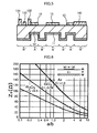
- FIG. 6 illustrates a relationship between the line width a, the substrate thickness b and the characteristic impedance Z 0 at a fixed line length.
- FIG. 6 shows that, as the line width a is narrower and the thickness b of the GaAs substrate 102 is thicker, the characteristic impedance Z 0 of the microstrip line 105 becomes higher. Further, although not illustrated in FIG. 6 , it has been known that, as the line length is longer, the characteristic impedance Z 0 becomes higher.
- the characteristic impedance Z 0 of the microstrip line 105 has been defined by mainly adjusting the line width a.
- attainment of the microstrip line 104 especially having a low impedance characteristic requires resolution of the following problems:
- the line width a has to be wide as shown in FIG. 6 .
- the length of the microstrip line 104 cannot be shortened due to the restrictions such as the device arrangement described above. Accordingly, the area occupied by the microstrip line 105 on a surface of the GaAs substrate 102 on which the microwave circuit is formed has become larger. Increasing the line width a of the microstrip line 105 in this way causes the problem that the size of the microwave circuit becomes larger. Further, when the line width a of the microstrip line 105 is increased, there is also a problem that the electric power of a microwave emitted from the microstrip line 105 to the open air increases.
- the part of the line where the line width is wide is only the vicinity of the junction with an active device and therefore enlargement of the microwave circuit resulting from increasing the line width can be restrained.
- attachment of a plurality of adjusting lines on the substrate is required, which disadvantageously results in that manufacture of the microwave circuit is difficult.
- the line width is wide even locally and therefore further miniaturization of the microwave circuit is difficult.
- a semiconductor circuit device including: a dielectric substrate; a plurality of active devices formed on the dielectric substrate; and a microstrip line formed on the dielectric substrate and electrically connecting the active devices, wherein a thickness of a first region of the dielectric substrate on which the microstrip line is formed is different from a thickness of a second region of the dielectric substrate on which the active devices are formed.
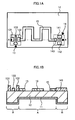
- FIG. 1A is a top view schematically illustrating a high frequency semiconductor circuit device with a microwave circuit according to a first embodiment of the present invention.
- FIG. 1B is a sectional view taken along a broken line A-A' in FIG. 1A .
- the microwave circuit in the semiconductor circuit device according to the first embodiment is formed on a GaAs substrate 12 having a conductor 11 on a rear face thereof.
- the microwave circuit includes, for example, two FETs 13, 14 functioning as active devices, and a microstrip line 15 connecting FET 13 to FET 14 each other.
- the FET 13 has a source electrode 131, a drain electrode 132 and a gate electrode 133.
- the FET 14 has a source electrode 141, a drain electrode 142 and a gate electrode 143.
- the microstrip line 15 connects, for example, the drain electrode 132 of the FET 13 to the gate electrode 143 of the FET 14 each other.
- Such a microstrip line 14 is made of, for example, Au.
- the thickness of a region A of the GaAs substrate 12 on which the microstrip line 15 is formed is thinner than the thickness of a region B of the GaAs substrate 12 on which FETs 13, 14 are formed.
- the characteristic impedance of the microstrip line 15 can be reduced without changing the length of the microstrip line 15. Accordingly, the line width of the microstrip line 14 can be narrower than a line with of a conventional microstrip line. Accordingly, when the line width of the microstrip line 14 is narrow in this way, the characteristic impedance of the microstrip line 14 sufficient to match an impedance of the FET 13 with an impedance of the FET 14 can be maintained.
- the microwave circuit can be miniaturized.
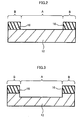
- a photosensitive resist is formed on the entire rear face of the GaAs substrate 12 and a resist mask 16 as shown in FIG. 2 is formed by patterning.
- the resist mask 16 has an opening in a region A in which the microstrip line 15 is formed on the GaAs substrate 11.
- a part of the GaAs substrate 11 is selectively removed by reactive ion etching (RIE) through the resist mask 16.
- RIE reactive ion etching
- the GaAs substrate 12 with partially different thickness as described in the present embodiment can be formed.
- FIG. 4A and FIG. 4B a second embodiment of the present invention will be described below.
- FIG. 4A is a top view schematically illustrating a high frequency semiconductor circuit device with a microwave circuit according to the second embodiment of the present invention.
- FIG. 4B is a sectional view taken along a broken line A-A' in FIG. 4A .
- the thickness of the region A of the GaAs substrate 12 on which the microstrip line 15 is formed is thicker than the thickness of the region B of the GaAs substrate 12 on which FETs 13, 14 are formed.
- a characteristic impedance of the microstrip line 15 can be increased without changing the width of the microstrip line 15. Accordingly, when a length of the microstrip line 15 is shortened, a characteristic impedance of the microstrip line 15 sufficient to match the impedance of the FET 13 with the impedance of the FET 14 can be maintained. In this case, since the line length can be shortened, the area occupied by the microstrip line 15 can be smaller than the area occupied by the conventional microstrip line. Accordingly, the microwave circuit can be miniaturized.
- the design for forming the microstrip line 15 is not limited by impedance matching, but limited by only device arrangement. Therefore, the flexibility in designing a circuit pattern can also be enhanced.
- the semiconductor circuit device according to the second embodiment is also excellent in the effect of radiating the heat generated at FETs 13, 14 because the thickness of the region B of the GaAs substrate 12 on which FETs 13, 14 are formed is thin.
- a manufacturing method for a GaAs substrate 11 in the semiconductor circuit device according to the second embodiment is essentially the same as that in the semiconductor circuit device according to the first embodiment and therefore detailed description thereof will not be repeated, but simple description will be made below.
- a resist mask having an opening in the region B of the GaAs substrate 11 and etching is performed using the resist to form the substrate 11.
- the thickness of the entire region A of the GaAs substrate 12 on which the microstrip line 15 is formed is different from the thickness of the region B of the GaAs substrate 12 on which FETs 13,14 are formed.
- the thickness of the region A of the GaAs substrate 12 may be adjusted along the shape of the microstrip line 14. Specifically, as shown in FIG. 5 which is a sectional view taken along the broken line A-A', the thickness of only a region A' with a microstrip line 15 formed on a surface of the GaAs substrate 12 is thinner than that of any other region B' with FETs 13, 14 formed on a surface of the GaAs substrate 12. In this case, the flexibility in designing the microstrip line 15 formed on the GaAs substrate 12 is enhanced.
- the GaAs substrate 12 is used as a dielectric substrate.
- any dielectric substrate which has conductivity and includes a dielectric with a dielectric constant of approximately 1 to 10, is applicable.
- Si or Al 2 O 3 is also applicable as the dielectric.
- microstrip line 15 made of Au may use any metal.
- an element to be connected is not limited to a FET.
- the present invention is applicable to a case where any of an active device, a passive device and a circuit including the active device and the passive device is required to be connected through a microstrip line for matching.
Landscapes
- Waveguides (AREA)
- Junction Field-Effect Transistors (AREA)
- Semiconductor Integrated Circuits (AREA)
Applications Claiming Priority (1)
| Application Number | Priority Date | Filing Date | Title |
|---|---|---|---|
| JP2008091226A JP2009246157A (ja) | 2008-03-31 | 2008-03-31 | 高周波帯半導体装置 |
Publications (2)
| Publication Number | Publication Date |
|---|---|
| EP2107607A2 true EP2107607A2 (de) | 2009-10-07 |
| EP2107607A3 EP2107607A3 (de) | 2010-11-24 |
Family
ID=40758860
Family Applications (1)
| Application Number | Title | Priority Date | Filing Date |
|---|---|---|---|
| EP09250959A Withdrawn EP2107607A3 (de) | 2008-03-31 | 2009-03-30 | Hochfrequenz-Halbleiterschaltvorrichtung |
Country Status (3)
| Country | Link |
|---|---|
| US (1) | US20090242988A1 (de) |
| EP (1) | EP2107607A3 (de) |
| JP (1) | JP2009246157A (de) |
Families Citing this family (1)
| Publication number | Priority date | Publication date | Assignee | Title |
|---|---|---|---|---|
| US9318450B1 (en) * | 2014-11-24 | 2016-04-19 | Raytheon Company | Patterned conductive epoxy heat-sink attachment in a monolithic microwave integrated circuit (MMIC) |
Citations (2)
| Publication number | Priority date | Publication date | Assignee | Title |
|---|---|---|---|---|
| JPH05235194A (ja) | 1991-11-29 | 1993-09-10 | Nec Corp | マイクロ波モノリシック集積回路 |
| JPH06196950A (ja) | 1992-12-25 | 1994-07-15 | Japan Energy Corp | マイクロ波回路 |
Family Cites Families (12)
| Publication number | Priority date | Publication date | Assignee | Title |
|---|---|---|---|---|
| US4069418A (en) * | 1976-03-02 | 1978-01-17 | The University Of Illinois Foundation | Detachable high-speed optoelectronic sampling head |
| US4030943A (en) * | 1976-05-21 | 1977-06-21 | Hughes Aircraft Company | Planar process for making high frequency ion implanted passivated semiconductor devices and microwave integrated circuits |
| JPS63222442A (ja) * | 1987-03-11 | 1988-09-16 | Sharp Corp | 高周波集積回路 |
| FR2631488B1 (fr) * | 1988-05-10 | 1990-07-27 | Thomson Hybrides Microondes | Circuit integre hyperfrequence de type planar, comportant au moins un composant mesa, et son procede de fabrication |
| JPH04270502A (ja) * | 1991-02-25 | 1992-09-25 | Mitsubishi Electric Corp | 半導体装置 |
| JPH06310547A (ja) * | 1993-02-25 | 1994-11-04 | Mitsubishi Electric Corp | 半導体装置及びその製造方法 |
| JP3189691B2 (ja) * | 1996-07-10 | 2001-07-16 | 株式会社村田製作所 | 高周波半導体デバイス |
| WO1998012751A1 (en) * | 1996-09-20 | 1998-03-26 | Hitachi, Ltd. | High-frequency integrated circuit device and its manufacture |
| JP2000022457A (ja) * | 1998-07-06 | 2000-01-21 | Fujitsu Ltd | 半導体装置 |
| JP2001267465A (ja) * | 2000-03-21 | 2001-09-28 | Toshiba Corp | 半導体装置 |
| US7453143B2 (en) * | 2003-03-05 | 2008-11-18 | Banpil Photonics, Inc. | High speed electronics interconnect and method of manufacture |
| JP2006173595A (ja) * | 2004-11-22 | 2006-06-29 | Matsushita Electric Ind Co Ltd | 半導体集積回路装置及びそれを用いた車載レーダシステム |
-
2008
- 2008-03-31 JP JP2008091226A patent/JP2009246157A/ja not_active Abandoned
-
2009
- 2009-03-30 EP EP09250959A patent/EP2107607A3/de not_active Withdrawn
- 2009-03-30 US US12/414,116 patent/US20090242988A1/en not_active Abandoned
Patent Citations (2)
| Publication number | Priority date | Publication date | Assignee | Title |
|---|---|---|---|---|
| JPH05235194A (ja) | 1991-11-29 | 1993-09-10 | Nec Corp | マイクロ波モノリシック集積回路 |
| JPH06196950A (ja) | 1992-12-25 | 1994-07-15 | Japan Energy Corp | マイクロ波回路 |
Also Published As
| Publication number | Publication date |
|---|---|
| EP2107607A3 (de) | 2010-11-24 |
| US20090242988A1 (en) | 2009-10-01 |
| JP2009246157A (ja) | 2009-10-22 |
Similar Documents
| Publication | Publication Date | Title |
|---|---|---|
| US6900482B2 (en) | Semiconductor device having divided active regions with comb-teeth electrodes thereon | |
| JP2012023212A (ja) | 半導体装置 | |
| JP2005159157A (ja) | 半導体装置 | |
| KR100300235B1 (ko) | 반도체의입출력접속구조 | |
| KR102549667B1 (ko) | 집적된 고조파 종단 특징부를 갖는 반도체 패키지 | |
| US8466368B2 (en) | High-frequency device | |
| US9035469B2 (en) | Semiconductor device that controls a negative resistive oscillation and obtains a high amplification output | |
| JP2012182306A (ja) | Mmic用パッケージ | |
| US20090242988A1 (en) | High frequency semiconductor circuit device | |
| US8125009B2 (en) | Mounting circuit substrate | |
| US9472497B2 (en) | Semiconductor device | |
| JPH11224911A (ja) | 高周波集積回路装置 | |
| US5898200A (en) | Microwave integrated circuit | |
| US9755313B2 (en) | Chip antenna for near field communication and method of manufacturing the same | |
| CN116169135A (zh) | 具有奇模振荡稳定电路的晶体管 | |
| KR102752888B1 (ko) | 선택 가능한 입출력 포트를 구비한 복수개의 전력 결합 증폭기를 포함하는 반도체 소자 | |
| JPH11346105A (ja) | マイクロ波平面回路 | |
| JP3839414B2 (ja) | 共振素子及び集積回路装置 | |
| JPH10200312A (ja) | マイクロ波集積回路 | |
| US20220293537A1 (en) | Semiconductor device and power amplifier | |
| JP5181424B2 (ja) | 高出力増幅器 | |
| JP4464104B2 (ja) | マイクロ波集積回路 | |
| JP2868939B2 (ja) | マイクロ波増幅器 | |
| JP4496176B2 (ja) | 半導体の入出力接続構造 | |
| JP2025039260A (ja) | 半導体装置 |
Legal Events
| Date | Code | Title | Description |
|---|---|---|---|
| PUAI | Public reference made under article 153(3) epc to a published international application that has entered the european phase |
Free format text: ORIGINAL CODE: 0009012 |
|
| 17P | Request for examination filed |
Effective date: 20090406 |
|
| AK | Designated contracting states |
Kind code of ref document: A2 Designated state(s): AT BE BG CH CY CZ DE DK EE ES FI FR GB GR HR HU IE IS IT LI LT LU LV MC MK MT NL NO PL PT RO SE SI SK TR |
|
| AX | Request for extension of the european patent |
Extension state: AL BA RS |
|
| PUAL | Search report despatched |
Free format text: ORIGINAL CODE: 0009013 |
|
| AK | Designated contracting states |
Kind code of ref document: A3 Designated state(s): AT BE BG CH CY CZ DE DK EE ES FI FR GB GR HR HU IE IS IT LI LT LU LV MC MK MT NL NO PL PT RO SE SI SK TR |
|
| AX | Request for extension of the european patent |
Extension state: AL BA RS |
|
| STAA | Information on the status of an ep patent application or granted ep patent |
Free format text: STATUS: THE APPLICATION HAS BEEN WITHDRAWN |
|
| 18W | Application withdrawn |
Effective date: 20110516 |
|
| AKX | Designation fees paid |
Designated state(s): DE FR GB |