EP2106972B1 - Zustiegshilfe mit verbessertem Spindelantrieb - Google Patents
Zustiegshilfe mit verbessertem Spindelantrieb Download PDFInfo
- Publication number
- EP2106972B1 EP2106972B1 EP09156978A EP09156978A EP2106972B1 EP 2106972 B1 EP2106972 B1 EP 2106972B1 EP 09156978 A EP09156978 A EP 09156978A EP 09156978 A EP09156978 A EP 09156978A EP 2106972 B1 EP2106972 B1 EP 2106972B1
- Authority
- EP
- European Patent Office
- Prior art keywords
- spindle
- coupling
- boarding aid
- previous
- set forth
- Prior art date
- Legal status (The legal status is an assumption and is not a legal conclusion. Google has not performed a legal analysis and makes no representation as to the accuracy of the status listed.)
- Active
Links
- 230000009194 climbing Effects 0.000 title abstract 2
- 230000007246 mechanism Effects 0.000 claims abstract description 45
- 230000008878 coupling Effects 0.000 claims abstract description 27
- 238000010168 coupling process Methods 0.000 claims abstract description 27
- 238000005859 coupling reaction Methods 0.000 claims abstract description 27
- 238000000034 method Methods 0.000 description 4
- 238000009434 installation Methods 0.000 description 3
- 230000000903 blocking effect Effects 0.000 description 2
- 238000006073 displacement reaction Methods 0.000 description 2
- 239000000314 lubricant Substances 0.000 description 2
- 238000006243 chemical reaction Methods 0.000 description 1
- 150000001875 compounds Chemical class 0.000 description 1
- 230000001419 dependent effect Effects 0.000 description 1
- 239000004519 grease Substances 0.000 description 1
- 238000011144 upstream manufacturing Methods 0.000 description 1
Images
Classifications
-
- B—PERFORMING OPERATIONS; TRANSPORTING
- B60—VEHICLES IN GENERAL
- B60R—VEHICLES, VEHICLE FITTINGS, OR VEHICLE PARTS, NOT OTHERWISE PROVIDED FOR
- B60R3/00—Arrangements of steps or ladders facilitating access to or on the vehicle, e.g. running-boards
- B60R3/02—Retractable steps or ladders, e.g. movable under shock
-
- B—PERFORMING OPERATIONS; TRANSPORTING
- B61—RAILWAYS
- B61D—BODY DETAILS OR KINDS OF RAILWAY VEHICLES
- B61D23/00—Construction of steps for railway vehicles
- B61D23/02—Folding steps for railway vehicles, e.g. hand or mechanically actuated
- B61D23/025—Folding steps for railway vehicles, e.g. hand or mechanically actuated electrically or fluid actuated
Definitions
- the present invention relates to a boarding aid for a passenger transport vehicle having a drive device for moving a step plate of the boarding aid by means of a rotary drive, wherein the drive device has at least one spindle mechanism.
- the passenger transport vehicle is a rail-bound vehicle or a motor vehicle.
- Boarding aids for passenger transport systems are known. For example, this is a ramp or a sliding step with associated Verstellantriebsvorraumplatz for a door entry of a passenger transport vehicle, wherein the respective tread plate between a retracted position and an extended position is movable to facilitate the approach of the occupants.
- Such approach aids are used in vehicles for passenger transport, such as buses or rail vehicles of public transport. They are known in various designs and generally facilitate entry and exit in that in the area of stops on the vehicles, the displaceable and / or pivotally mounted footboard is extended. They serve to bridge gaps (for example at platforms) or are also used for height compensation. Finally, they facilitate or allow wheelchair users access to the vehicles.
- a boarding aid has one or more spindle mechanisms.
- a spindle mechanism comprises a spindle and a spindle nut running on its thread. Such spindle mechanisms are provided to convert a rotational movement in the sliding movement of the tread plate and to these on and extend.
- a spindle is driven in rotation, on the thread of a spindle nut runs, which is connected to the tread plate.
- the spindle mechanism is usually adjusted to the required travel before installation. This is one Clamping connection between the spindle and the driving drive shaft or a toothed belt pulley, if the drive takes place via toothed belt provided.
- An adjustment of the spindle mechanism not only during installation but possibly as a readjustment during operation may be necessary in particular when the shift is made by two synchronously rotating spindles, as is the case for example in known ramps or sliding steps, at the flanks of each one Spindle mechanism is located.
- the adjustment path of the two spindle nuts must be precisely matched to prevent tilting of the sliding step or the ramp. Otherwise, it can lead to increased wear or even blocking occur.
- a symmetrical design of the two spindle drives for example, it depends on an exact arrangement of the two spindle nut in each case the same point of the spindle in order to avoid the aforementioned problems.
- the invention is therefore based on the object to provide a boarding aid with at least one spindle mechanism in the associated drive device, wherein the spindle mechanism is easier to adjust and is more reliable.
- This object is achieved by the entry-level system according to claim 1.
- Advantageous embodiments are the subject of the dependent claims.
- the invention relates to a boarding aid for a passenger transport vehicle with a drive device for moving a footboard of the boarding aid by means of a rotary drive.
- a rotary drive for example, it is an electric motor rotary drive.
- tread plate is to be interpreted broadly. For example, it is a sliding door or a ramp to facilitate the entry and exit for people or in particular wheelchair users in or out of the passenger transport vehicle. This is the tread plate in general moved between a retracted position and an extended position to facilitate the entry and exit in the extended position by the extended tread plate.
- Tread plates are used for bridging gaps (for example, on platforms) or for height compensation. Finally, they facilitate or enable, for example, wheelchair users access to the vehicles. After completion of the training and entry phase and possibly after closing the vehicle doors, the tread plate is returned to its retracted position by motor.
- the drive device comprises at least one spindle mechanism.
- This spindle mechanism is used for the exact yet rapid conversion of the rotational movement of the rotary drive in a substantially translational movement of the treadle.
- the spindle mechanism includes a threaded spindle and associated spindle nut, i. a running on the thread nut.
- the drive mechanism according to the invention is characterized in that the drive mechanism further comprises a lockable coupling which is releasable in an adjustment position for adjusting the tread plate.
- the coupling between tread plate and spindle mechanism is arranged. Adjustment of the tread plate means that by loosening the clutch, the position of the tread plate and thus its displacement with respect to the spindle mechanism and thus the vehicle can be changed. By attaching this coupling between tread plate and spindle mechanism, i. So in the immediate vicinity of the treadle, this coupling is easily accessible for adjusting the sliding movement of the tread plate.
- this coupling is easily accessible for adjusting the sliding movement of the tread plate.
- the spindle mechanism i.
- the coupling between treadle and spindle nut or between treadle and spindle can be provided depending on which component of spindle or spindle nut of the spindle mechanism is rotated by the rotary drive. Due to the footboard-near arrangement, it is exposed to far fewer lubricants, as it usually exits in the vicinity of the rotary drive.
- the rotationally fixed locking of the coupling can be done in various ways known in the art.
- the rotationally fixed locking by a non-positive clamping or a positive connection causes.
- the locking can be realized comparatively easily and safely.
- the drive mechanism comprises two spindle mechanisms for moving the tread plate, wherein at least one clutch is provided.
- an adjustment of the adjustment of the associated spindle mechanism can be made to the adjustment of the second spindle mechanism.
- the position of the tread plate can be adjusted in a simple manner such that their lateral flanks, which are mostly guided by the spindle mechanisms, run parallel to the spindles. Tilting with increased wear and the risk of blocking can be avoided.
- a symmetrical design of the two spindle drives so exactly symmetrical arrangement of the two spindle nuts can be achieved on the respective spindle to avoid the above problems.
- the spindle nut of the spindle mechanism by means of the clutch relative to the foot plate can be fixed.
- the spindle nut of the spindle mechanism is connected to the running board by the coupling, while the adjustment of the running board is effected by the rotation of the spindle.
- the attachment of the spindle nut has proven to be very reliable on the running board.
- the spindle nut or the spindle (depending on the configuration of the spindle mechanism) with respect to the tread plate at least in a predetermined range of rotation for adjustment rotatable.
- At least a part of the coupling relative to the spindle nut or the spindle can be fixed in defined positions.
- the assembly and in particular the adjustment can be accelerated.
- the coarse adjustment by a positive connection, such as teeth, between the part of the coupling and the spindle nut or spindle. The actual adjustment takes place after coarse adjustment in the adjustment position of the clutch.
- the invention further relates to a passenger transport vehicle with a boarding aid in one of the previously described embodiments.
- the invention further relates to a method for assembling and adjusting a step plate of a boarding aid for a passenger transport vehicle, wherein the boarding aid comprises a drive device for moving a step plate of the boarding aid by means of a rotary drive, and the drive device comprises at least one spindle mechanism comprising a spindle and a spindle nut, the drive mechanism further comprising a lockable clutch releasable to adjust the tread plate in an adjustment position disposed between the tread plate and the spindle mechanism, the method comprising: a step of mounting the spindle mechanism to a subsequent adjustment step wherein; Adjustment position of the clutch, the position of the tread plate is adjusted and a subsequent locking step in which the coupling is locked.
- a coarse adjustment step upstream of the adjustment step is provided in which a part of the coupling with the spindle mechanism is fixed in predetermined positions.
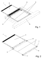
- Fig. 1 1 shows an approach and extendable tread plate 2 (shown here without cover plate and bottom cover).
- the tread plate 2 is attached to a frame 5 of the vehicle, not shown.
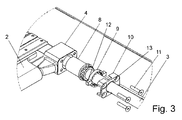
- the sliding movement is achieved by two mirror-symmetrically constructed and symmetrically arranged spindle mechanisms, each having two driven spindles 3 and housed in a housing 4 and therefore in FIGS. 1 and 2 not to be seen spindle nuts 8 (see FIG. 3 ). If the rotary drive of the drive device not shown in detail set in motion, are on the in FIG. 2 shown toothed belt 6 and the associated toothed belt pulleys 7, the two spindles 4 synchronously rotated.
- spindle nuts 8 move along the spindles 3 and cause so depending on the direction of rotation of the spindles 3 a method of the tread plate 2 in the off or retraction. It is absolutely necessary that the spindle nuts 8 move to exactly "same height" so that it does not lead to tilting of the tread plate 2. This leads to increased wear of the spindle nuts 8 and / or the spindles 3, or in the worst case to block the movement of the treadboard second
- the coupling 9, 10 is provided between the tread plate 2 and the housing 4 and the spindle mechanism 3, 8, here the spindle nut 8.
- the coupling 9, 10 serves to fix the spindle nut 8 with respect to the tread plate 2 or the housing 4 and has a locking position explained below.
- it comprises an adjustment position, in which the spindle nut 8 is not connected to the tread plate 2 or the housing 4 in a rotationally fixed manner and is rotatable relative to the footboard 2 or the housing 4 for its adjustment.
- an adjustment ring 9 is provided, which can be placed in the assembly on the coarse aligned spindle nut 8 due to a mutual toothing in defined positions and rotatably cooperates with this.
- the adjusting ring 9 is overlapped by a hood 10 in the further assembly.
- the hood 10 is connected to the housing 4 by means of screws 11. When the screws 11 are loosened, the coupling 9, 10 is in the adjustment position. It can via the extensions 12, which are accessible via the recesses 13 of the hood 10, the rotation of the adjusting ring 9 and thus the spindle nut 8 with respect to the housing 4 and thus an adjustment of the position or the orientation of the tread plate 2 can be achieved.
- the adjustment range is limited to the game of the extensions 12 in the recesses 13. With tightening the screws 11, the locking position of the clutch 9, 10 is reached, and it is provided for a non-positive and rotationally fixed clamping of the adjusting ring 9 between the hood 10 and the housing 4, which ensures a determination of the spindle nut 8 relative to the footboard 2.
- a positive connection between the adjusting ring 9 and the hood 10 and the housing 4 may be provided to lock the coupling 9, 10.
Landscapes
- Engineering & Computer Science (AREA)
- Mechanical Engineering (AREA)
- Transmission Devices (AREA)
- Automatic Tape Cassette Changers (AREA)
- Lubricants (AREA)
- Invalid Beds And Related Equipment (AREA)
- Transition And Organic Metals Composition Catalysts For Addition Polymerization (AREA)
- Vehicle Step Arrangements And Article Storage (AREA)
- Body Structure For Vehicles (AREA)
- Devices For Checking Fares Or Tickets At Control Points (AREA)
- Accommodation For Nursing Or Treatment Tables (AREA)
- Vehicle Body Suspensions (AREA)
- Portable Nailing Machines And Staplers (AREA)
Description
- Die vorliegende Erfindung betrifft eine Zustiegshilfe für ein Personenbeförderungsfahrzeug mit einer Antriebsvorrichtung zur Bewegung einer Trittplatte der Zustiegshilfe mittels eines Drehantriebs, wobei die Antriebsvorrichtung wenigstens einen Spindelmechanismus aufweist. Beispielsweise handelt sich bei dem Fahrzeug zur Personenbeförderung um ein schienengebundenes Fahrzeug oder ein Kraftfahrzeug.
- Zustiegshilfen für Personenbeförderungssysteme sind bekannt. Beispielsweise handelt es sich dabei um eine Rampe oder einen Schiebetritt mit zugehöriger Verstellantriebsvorrichtung für einen Türeinstieg eines Personenbeförderungsfahrzeuges, wobei die jeweilige Trittplatte zwischen einer eingefahrenen Stellung und einer ausgefahrenen Stellung bewegbar ist, um den Zustieg der Insassen zu erleichtern. Derartige Zustiegshilfen werden bei Fahrzeugen zur Personenbeförderung, beispielsweise bei Bussen oder Schienenfahrzeugen des öffentlichen Nahverkehrs, eingesetzt. Sie sind in vielfältigen Bauformen bekannt und erleichtern allgemein den Ein- und Ausstieg dadurch, dass im Bereich von Haltestellen an den Fahrzeugen die verschiebbar und/oder verschwenkbar gelagerte Trittplatte ausgefahren wird. Sie dienen dabei der Überbrückung von Spalten (beispielsweise bei Bahnsteigen) oder werden auch zum Höhenausgleich eingesetzt. Schließlich erleichtern oder ermöglichen sie Rollstuhlfahrern den Zugang in die Fahrzeuge. Nach Beendigung der Aus- und Einstiegsphase und eventuell nach dem Schließen der Fahrzeugtüren wird die Trittplatte wieder in ihre Ruhestellung zurückgebracht. Motorisch betriebene Schiebetritte sind beispielsweise in den Druckschriften
US 6 848 735 ,DE 20 2007 000 912 U1 ,DE 20 2005 012 584 U1 undDE 20 2006 017 716 U1 beschrieben. - Es ist ferner bekannt, dass eine Zustiegshilfe einen oder mehrere Spindelmechanismen aufweist. Ein Spindelmechanismus umfasst eine Spindel und eine auf deren Gewinde ablaufende Spindelmutter. Derartige Spindelmechanismen sind vorgesehen, um eine Drehbewegung in die Verschiebebewegung der Trittplatte umzuwandeln und um diese ein- und auszufahren. Bei den bekannten Systemen wird eine Spindel rotierend angetrieben, auf deren Gewinde eine Spindelmutter abläuft, die mit der Trittplatte verbunden ist. Der Spindelmechanismus wird in der Regel auf den erforderlichen Stellweg vor dem Einbau justiert. Dazu ist eine Klemmverbindung zwischen Spindel und der sie antreibenden Antriebswelle oder einer Zahnriemenscheibe, falls der Antrieb über Zahnriemen erfolgt, vorgesehen. Da die Zugänglichkeit dieser Verbindung in der jeweiligen Einbauumgebung sehr eingeschränkt ist, kann eine nachträgliche Justierung, wenn überhaupt, nur schwer vorgenommen werden. Zudem stellt sich das Problem, dass die Klemmverbindung, da sie sich in der Nähe der Antriebvorrichtung befindet, schnell Schmiermitteln, wie Öl oder Fett, ausgesetzt ist und somit verstärkt die Gefahr besteht, dass dies zu einem Lösen der Verbindung führt.
- Eine Justage des Spindelmechanismus nicht nur beim Einbau sondern möglicherweise als Nachjustage im laufenden Betrieb kann insbesondere dann erforderlich sein, wenn die Verschiebung durch zwei synchron rotierende Spindeln vorgenommen wird, wie es beispielsweise bei bekannten Rampen oder Schiebetritten der Fall ist, an deren Flanken sich jeweils ein Spindelmechanismus befindet. Um für ein gleichmäßiges Verschieben der Rampe oder des Schiebetritts zu sorgen, ist der Verstellweg der beiden Spindelmuttern genau aufeinander abzustimmen, damit ein Verkanten des Schiebetritts oder der Rampe verhindert wird. Andernfalls kann es zu erhöhtem Verschleiß kommen oder gar ein Blockieren auftreten. Bei einer symmetrischen Auslegung der beiden Spindelantriebe kommt es beispielsweise auf eine genaue Anordnung der beiden Spindelmutter an jeweils gleicher Stelle der Spindel an, um die zuvor genannten Probleme zu vermeiden.
- Der Erfindung liegt daher die Aufgabe zugrunde, eine Zustiegshilfe mit wenigstens einem Spindelmechanismus in der zugehörigen Antriebsvorrichtung bereitzustellen, wobei der Spindelmechanismus leichter zu justieren ist und zuverlässiger ist. Diese Aufgabe wird durch das Einstiegssystem gemäß Anspruch 1 gelöst. Vorteilhafte Ausgestaltungen sind Gegenstand der abhängigen Ansprüche.
- Die Erfindung betrifft eine Zustiegshilfe für ein Personenbeförderungsfahrzeug mit einer Antriebsvorrichtung zur Bewegung einer Trittplatte der Zustiegshilfe mittels eines Drehantriebs. Beispielsweise handelt es sich um einen elektromotorischen Drehantrieb. Der Begriff Trittplatte ist weit auszulegen. Beispielsweise handelt es sich um eine Schiebtritt oder eine Rampe, um den Ein- und Ausstieg für Personen oder insbesondere Rollstuhlfahrer in beziehungsweise aus dem Personenbeförderungsfahrzeug zu erleichtern. Dazu wird die Trittplatte im Allgemeinen zwischen einer eingefahrenen Stellung und einer ausgefahrenen Stellung bewegt, um in der ausgefahrenen Stellung den Ein- und Ausstieg durch die ausgefahrene Trittplatte zu erleichtern. Trittplatten werden dabei zur Überbrückung von Spalten (beispielsweise bei Bahnsteigen) oder auch zum Höhenausgleich eingesetzt. Schließlich erleichtern oder ermöglichen sie beispielsweise Rollstuhlfahrern den Zugang in die Fahrzeuge. Nach Beendigung der Aus- und Einstiegsphase und eventuell nach dem Schließen der Fahrzeugtüren wird die Trittplatte wieder in ihre eingefahrene Stellung motorisch zurückgebracht.
- Die erfindungsgemäße Antriebsvorrichtung umfasst wenigstens einen Spindelmechanismus. Dieser Spindelmechanismus dient der exakten und doch schnellen Umwandlung der Drehbewegung des Drehantriebs in eine im Wesentlichen translatorische Bewegung der Trittplatte. Der Spindelmechanismus umfasst eine Spindel mit Gewindegang und eine zugehörige Spindelmutter, d.h. eine auf dem Gewinde ablaufende Mutter.
- Der erfindungsgemäße Antriebsmechanismus zeichnet sich dadurch aus, dass der Antriebsmechanismus ferner eine arretierbare Kupplung umfasst, die in einer Justierstellung zur Justierung der Trittplatte lösbar ist. Erfindungsgemäß ist die Kupplung zwischen Trittplatte und Spindelmechanismus angeordnet. Justierung der Trittplatte meint, dass durch Lösen der Kupplung die Lage der Trittplatte und damit ihres Verschiebewegs bezüglich des Spindelmechanismus und damit des Fahrzeugs geändert werden kann. Durch Anbringen dieser Kupplung zwischen Trittplatte und Spindelmechanismus, d.h. also in unmittelbarer Nähe der Trittplatte, ist diese Kupplung für die Justierung der Verschiebebewegung der Trittplatte leicht zugänglich. Je nach Ausgestaltung des Spindelmechanismus, d.h. je nach dem welche Komponente aus Spindel oder Spindelmutter des Spindelmechanismus vom Drehantrieb in Drehung versetzt wird, kann die Kupplung zwischen Trittplatte und Spindelmutter oder zwischen Trittplatte und Spindel vorgesehen sein. Durch die Trittbrett-nahe Anordnung ist sie weit weniger Schmiermitteln ausgesetzt, wie es in der Regel in der Nähe des Drehantriebs austritt. Die drehfeste Arretierung der Kupplung kann auf diverse dem Fachmann bekannte Arten erfolgen.
- Bevorzugt wird die drehfeste Arretierung durch eine kraftschlüssige Klemmung oder eine formschlüssige Verbindung, beispielsweise wechselseitige Verzahnung, bewirkt. Dadurch kann vergleichsweise einfach und sicher die Arretierung realisiert werden.
- Bevorzugt umfasst der Antriebsmechanismus zwei Spindelmechanismen zur Bewegung der Trittplatte, wobei wenigstens eine Kupplung vorgesehen ist. Mittels der Kupplung kann eine Justierung des Verstellweges des zugehörigen Spindelmechanismus auf den Verstellweg des zweiten Spindelmechanismus vorgenommen werden. Dadurch kann auf einfache Weise die Lage der Trittplatte so justiert werden, dass ihre seitlichen Flanken, die zumeist durch die Spindelmechanismen geführt sind, parallel zu den Spindeln verlaufen. Ein Verkanten mit erhöhtem Verschleiß und der Gefahr des Blockierens kann so vermieden werden. Bei einer symmetrischen Auslegung der beiden Spindelantriebe kann so eine genau symmetrische Anordnung der beiden Spindelmuttern auf der jeweiligen Spindel erreicht werden, um oben genannten Probleme zu vermeiden.
- Bevorzugt ist die Spindelmutter des Spindelmechanismus mittels der Kupplung gegenüber der Trittplatte festlegbar. Anders ausgedrückt, die Spindelmutter des Spindelmechanismus ist durch die Kupplung mit dem Trittbrett verbunden, während die Verstellung des Trittbretts durch die Drehung der Spindel bewirkt wird. In der Praxis hat sich die Befestigung der Spindelmutter am Trittbrett als sehr zuverlässig erwiesen.
- In einer bevorzugten Ausführungsform ist in der Justierstellung der Kupplung die Spindelmutter oder die Spindel (je nach Ausgestaltung des Spindelmechanismus) gegenüber der Trittplatte wenigstens in einem vorgegebenen Drehbereich zur Justage verdrehbar. Durch das Verdrehen kann die Verstellung schnell, präzise und ohne Zuhilfenahme spezieller Werkzeuge erfolgen.
- In einer bevorzugten Ausführungsform ist zur Bereitstellung einer Grobeinstellung wenigstens ein Teil der Kupplung gegenüber der Spindelmutter oder der Spindel in definierten Stellungen festlegbar. Dadurch kann die Montage und insbesondere die Justierung beschleunigt werden. Bevorzugt erfolgt in einer Ausgestaltung die Grobeinstellung durch eine formschlüssige Verbindung, beispielsweise Verzahnung, zwischen dem Teil der Kupplung und der Spindelmutter oder Spindel. Die eigentliche Justierung erfolgt nach erfolgter Grobeinstellung in der Justierstellung der Kupplung.
- Die Erfindung betrifft ferner ein Personenbeförderungsfahrzeug mit einer Zustiegshilfe in einer der zuvor beschriebenen Ausgestaltungen.
- Die Erfindung betrifft ferner ein Verfahren zur Montage und Justage einer Trittplatte einer Zustiegshilfe für ein Personenbeförderungsfahrzeug, wobei die Zustiegshilfe eine Antriebsvorrichtung zur Bewegung einer Trittplatte der Zustiegshilfe mittels eines Drehantriebs umfasst, und die Antriebsvorrichtung wenigstens einen Spindelmechanismus aufweist, der eine Spindel und eine Spindelmutter umfasst, wobei der Antriebsmechanismus ferner eine arretierbare und zur Justage der Trittplatte in einer Justierstellung lösbare Kupplung umfasst, die zwischen Trittplatte und Spindelmechanismus angeordnet ist, wobei das Verfahren Folgendes umfasst: einen Montegschritt, bei dem der Spindelmechanismus montiert wird, einen nachfolgenden Justierschritt, bei dem in der Justierstellung der Kupplung die Lage der Trittplatte justiert wird und einen nachfolgenden Arretierschritt, bei die Kupplung arretiert wird. In einer weiteren Ausgestaltung des erfindungsgemäßen Verfahrens ist ein dem Justierschritt vorgeschalteter Grobeinstellschritt vorgesehen, bei dem ein Teil der Kupplung mit dem Spindelmechanismus in vorgegebenen Stellungen festgelegt wird.
- Im Folgenden wird anhand der beigefügten Zeichnungen ein Ausführungsbeispiel der erfindungsgemäßen Zustiegshilfe näher erläutert, ohne die Erfindung auf die gezeigten Beispiele einzuschränken.
- In den Zeichnungen zeigen:
-
Fig. 1 in perspektivischer Darstellung eine Zustiegshilfe für ein Personenbeförderungsfahrzeug mit dem zugehörigen Halterahmen zur Befestigung am Fahrzeug; -
Fig. 2 in perspektivischer Darstellung die Trittplatte mit Teilen der Antriebsvorrichtung; -
Fig. 3 in Explosionsansicht den zugehörigen Spindelmechanismus mit Kupplung. -
Fig. 1 zeigt eine Ausgestaltung der erfindungsgemäßen Zustiegshilfe 1. Die Zustiegshilfe 1 umfasst eine ein- und ausfahrbare Trittplatte 2 (hier ohne Deckplatte und Bodenabdeckung dargestellt). Die Trittplatte 2 wird an einem Rahmen 5 des nicht näher dargestellten Fahrzeugs befestigt. Die Verschiebebewegung wird durch zwei spiegelbildlich aufgebaute und symmetrisch angeordnete Spindelmechanismen erreicht, die jeweils zwei angetriebene Spindeln 3 und in einem Gehäuse 4 aufgenommene und daher inFigur 1 und 2 nicht zu sehende Spindelmuttern 8 (sieheFigur 3 ) umfassen. Wird der nicht näher gezeigte Drehantrieb der Antriebsvorrichtung in Gang gesetzt, werden über den inFigur 2 gezeigten Zahnriemen 6 und die zugehörigen Zahnriemenscheiben 7 die beiden Spindeln 4 synchron in Drehung versetzt. Dabei bewegen sich die später im Einzelnen erläuterten Spindelmuttern 8 entlang der Spindeln 3 und bewirken so je nach Drehrichtung der Spindeln 3 ein Verfahren der Trittplatte 2 in Aus- beziehungsweise Einfahrrichtung. Dabei ist es unbedingt erforderlich, dass die Spindelmuttern 8 auf exakt "gleicher Höhe" verfahren, damit es nicht zu einem Verkanten der Trittplatte 2 kommt. Dies führt zu erhöhtem Verschleiß der Spindelmuttern 8 und/oder der Spindeln 3, bzw. im schlimmsten Fall zum Blockieren der Bewegung der Trittplatte 2. - Zur Justierung ist wenigstens eine der beiden Spindelmechanismen 3, 8 mit einer Kupplung 9, 10 versehen, die im Detail in
Figur 3 zu erkennen ist. Die Kupplung 9, 10 ist zwischen der Trittplatte 2 beziehungsweise dem Gehäuse 4 und dem Spindelmechanismus 3, 8, hier der Spindelmutter 8, vorgesehen. Sie dient einerseits der Festlegung der Spindelmutter 8 gegenüber der Trittplatte 2 beziehungsweise dem Gehäuse 4 und weist dazu eine nachfolgend erläuterte Arretierstellung auf. Sie umfasst andererseits eine Justierstellung, bei der die Spindelmutter 8 nicht mit der Trittplatte 2 beziehungsweise dem Gehäuse 4 drehfest verbunden ist und gegenüber dem Trittbrett 2 beziehungsweise dem Gehäuse 4 zu dessen Justierung verdrehbar ist. Zur Grobeinstellung der Spindelmutter 8 ist ein Einstellring 9 vorgesehen, der bei der Montage auf die grob ausgerichtete Spindelmutter 8 aufgrund einer wechselseitigen Verzahnung in definierten Stellungen aufgesetzt werden kann und mit dieser drehbar zusammenwirkt. Der Einstellring 9 wird bei der weiteren Montage von einer Haube 10 übergriffen. Die Haube 10 wird mit dem Gehäuse 4 mittels Schrauben 11 verbunden. Bei gelösten Schrauben 11 befindet sich die Kupplung 9, 10 in der Justierstellung. Dabei kann über die Fortsätze 12, die über die Ausnehmungen 13 der Haube 10 zugänglich sind, die Verdrehung des Einstellrings 9 und damit der Spindelmutter 8 bezüglich des Gehäuses 4 und damit einer Justierung der Lage bzw. der Ausrichtung der Trittplatte 2 erreicht werden. Der Justierbereich ist dabei auf das Spiel der Fortsätze 12 in den Ausnehmungen 13 beschränkt. Mit Anziehen der Schrauben 11 wird die Arretierstellung der Kupplung 9, 10 erreicht, und es wird für eine kraftschlüssige und drehfeste Klemmung des Einstellrings 9 zwischen der Haube 10 und dem Gehäuse 4 gesorgt, was für eine Festlegung der Spindelmutter 8 gegenüber dem Trittbrett 2 sorgt. Neben einer reinen kraftschlüssigen Verbindung, wie beschrieben, kann auch eine formschlüssige Verbindung zwischen dem Einstellring 9 und der Haube 10 beziehungsweise dem Gehäuse 4 vorgesehen sein, um die Kupplung 9, 10 zu arretieren.
Claims (8)
- Zustiegshilfe (1) für ein Personenbeförderungsfahrzeug mit einer Antriebsvorrichtung zur Bewegung einer Trittplatte (2) der Zustiegshilfe (1) mittels eines Drehantriebs, wobei die Antriebsvorrichtung wenigstens einen Spindelmechanismus (3, 8) aufweist, umfassend eine Spindel (3) und eine Spindelmutter (8), dadurch gekennzeichnet, dass der Antriebsmechanismus ferner eine arretierbare und zur Justage der Trittplatte in einer Justierstellung lösbare Kupplung (9, 10) umfasst, die zwischen Trittplatte (2) und Spindelmechanismus (3, 8) angeordnet ist.
- Zustiegshilfe (1) gemäß dem vorhergehenden Anspruch, dadurch gekennzeichnet, dass der Antriebsmechanismus zwei Spindelmechanismen (3, 8) zur Bewegung der Trittplatte (2) umfasst und wenigstens eine Kupplung (9, 10) vorgesehen ist.
- Zustiegshilfe (1) nach einem der vorhergehenden Ansprüche, dadurch gekennzeichnet, dass die Spindelmutter (8) des Spindelmechanismus (3, 8) mittels der Kupplung (9, 10) gegenüber der Trittplatte (2) arretierbar ist.
- Zustiegshilfe (1) nach einem der vorhergehenden Ansprüche, dadurch gekennzeichnet, dass in der Justierstellung der Kupplung (9, 10) die Spindelmutter (8) oder die Spindel (3) gegenüber der Trittplatte (2) wenigstens in einem vorgegebenen Drehbereich (13) zur Justage verdrehbar ist.
- Zustiegshilfe (1) nach einem der vorhergehenden Ansprüche, dadurch gekennzeichnet, dass zur Grobeinstellung wenigstens ein Teil der Kupplung (9) gegenüber der Spindelmutter (8) oder der Spindel (3) in definierten Stellungen festlegbar ist.
- Zustiegshilfe (1) nach dem vorhergehenden Anspruch, dadurch gekennzeichnet, dass zur Grobeinstellung eine formschlüssige Verbindung, beispielsweise Verzahnung, zwischen dem Teil der Kupplung (9) und der Spindelmutter (8) oder der Spindel (3) vorgesehen ist.
- Zustiegshilfe (1) nach einem der vorhergehenden Ansprüche, dadurch gekennzeichnet, dass die Arretierung der Kupplung durch eine kraftschlüssige Klemmung (4, 11, 13) oder eine formschlüssige Verbindung bewirkt wird.
- Personenbeförderungsfahrzeug, gekennzeichnet durch eine Zustiegshilfe (1) nach einem der vorhergehenden Ansprüche.
Priority Applications (1)
| Application Number | Priority Date | Filing Date | Title |
|---|---|---|---|
| PL09156978T PL2106972T3 (pl) | 2008-04-01 | 2009-03-31 | Urządzenie wspomagające wsiadanie z udoskonalonym napędem wrzecionowym |
Applications Claiming Priority (1)
| Application Number | Priority Date | Filing Date | Title |
|---|---|---|---|
| DE202008004517U DE202008004517U1 (de) | 2008-04-01 | 2008-04-01 | Zustiegshilfe mit verbessertem Spindelantrieb |
Publications (2)
| Publication Number | Publication Date |
|---|---|
| EP2106972A1 EP2106972A1 (de) | 2009-10-07 |
| EP2106972B1 true EP2106972B1 (de) | 2010-09-15 |
Family
ID=40823007
Family Applications (1)
| Application Number | Title | Priority Date | Filing Date |
|---|---|---|---|
| EP09156978A Active EP2106972B1 (de) | 2008-04-01 | 2009-03-31 | Zustiegshilfe mit verbessertem Spindelantrieb |
Country Status (5)
| Country | Link |
|---|---|
| EP (1) | EP2106972B1 (de) |
| AT (1) | ATE481272T1 (de) |
| DE (2) | DE202008004517U1 (de) |
| ES (1) | ES2351252T3 (de) |
| PL (1) | PL2106972T3 (de) |
Families Citing this family (2)
| Publication number | Priority date | Publication date | Assignee | Title |
|---|---|---|---|---|
| AT513813B1 (de) * | 2013-01-14 | 2014-10-15 | Knorr Bremse Ges Mit Beschränkter Haftung | Schiebetritt für ein Schienenfahrzeug oder ein Kraftfahrzeug |
| JP7444182B2 (ja) * | 2022-01-28 | 2024-03-06 | トヨタ自動車株式会社 | 車両用スロープ展開装置 |
Family Cites Families (9)
| Publication number | Priority date | Publication date | Assignee | Title |
|---|---|---|---|---|
| GB745918A (en) * | 1953-02-27 | 1956-03-07 | Harold Edgar Chadwick | An adjustable and retractable step |
| AT254099B (de) * | 1965-07-16 | 1967-05-10 | Braunschweigische Maschb Ansta | Pendelnd aufgehängte Zentrifuge, insbesondere Zuckerzentrifuge |
| DE4112425A1 (de) * | 1991-04-16 | 1992-10-22 | Siemens Ag | Mit einem elektrischen drehantrieb in antriebsverbindung bringbare schwenkstufe |
| DE4441929C2 (de) * | 1994-11-24 | 2001-09-20 | Geze Gmbh | Zustiegsvorrichtung für Fahrzeuge, insbesondere Schienenfahrzeuge oder Kraftfahrzeuge, insbesondere für Niederfluromnibusse |
| US5775232A (en) * | 1997-02-14 | 1998-07-07 | Vapor Corporation | Bridge plate for a mass transit vehicle |
| US6848735B1 (en) * | 2003-06-19 | 2005-02-01 | Monaco Coach Corporation | Stepwell cover apparatus |
| DE202005012584U1 (de) | 2005-07-29 | 2005-12-01 | Hübner Transportation GmbH | Rampe für einen Türeinstieg eines Personenbeförderungsfahrzeugs |
| DE202006017716U1 (de) | 2005-11-17 | 2007-03-01 | Kircher, Werner | Zustiegs- und/oder Zufahrtshilfe mit einer beweglichen Trittplatte zur Erfassung von vertikalen und/oder horizontalen, auf die Trittplatte einwirkenden Störkräften an Fahrzeugen zur Personenbeförderung |
| DE202007000912U1 (de) | 2007-01-18 | 2007-04-05 | Kircher, Werner | Zustiegs- und/oder Zufahrtshilfe für Fahrzeuge mit Personenbeförderung |
-
2008
- 2008-04-01 DE DE202008004517U patent/DE202008004517U1/de not_active Expired - Lifetime
-
2009
- 2009-03-31 DE DE502009000090T patent/DE502009000090D1/de active Active
- 2009-03-31 ES ES09156978T patent/ES2351252T3/es active Active
- 2009-03-31 PL PL09156978T patent/PL2106972T3/pl unknown
- 2009-03-31 AT AT09156978T patent/ATE481272T1/de active
- 2009-03-31 EP EP09156978A patent/EP2106972B1/de active Active
Also Published As
| Publication number | Publication date |
|---|---|
| PL2106972T3 (pl) | 2011-03-31 |
| ATE481272T1 (de) | 2010-10-15 |
| ES2351252T3 (es) | 2011-02-02 |
| EP2106972A1 (de) | 2009-10-07 |
| DE502009000090D1 (de) | 2010-10-28 |
| DE202008004517U1 (de) | 2009-08-13 |
Similar Documents
| Publication | Publication Date | Title |
|---|---|---|
| EP3237254B1 (de) | Schiebetritt mit hub- und rampenfunktion | |
| EP1791717B1 (de) | Verstellvorrichtung, insbesondere für den sitz eines fahrzeugs | |
| DE69300030T2 (de) | Einstellbare Lenksäuleneinheit für ein Kraftfahrzeug. | |
| EP1587701B1 (de) | Schwenkschiebetür für fahrzeuge | |
| AT405155B (de) | Schwenkschiebetür für fahrzeuge | |
| DE69319423T2 (de) | Schwenkeinrichtung | |
| EP1031301A1 (de) | Verstellvorrichtung für einen Sitz oder eine Liege, insbesondere für ein Bett | |
| DE102023117792A1 (de) | Klapptischanordnung für ein Fahrzeug | |
| WO2016058581A1 (de) | Kopfstütze für einen fahrzeugsitz | |
| EP2591192A1 (de) | Vorrichtung zum einstellen und arretieren der lage einer führungsschiene für eine verstellbare fensterscheibe in einer fahrzeugtür | |
| EP2106972B1 (de) | Zustiegshilfe mit verbessertem Spindelantrieb | |
| DE102009012776B3 (de) | Fahrzeugsitz | |
| DE3882164T2 (de) | Einstellvorrichtung für das Schultergurthalteelement eines Sicherheitsgurtes. | |
| EP3665349A1 (de) | Türverschluss | |
| DE19702889C2 (de) | Antriebseinrichtung für einen Schließmechanismus und/oder eine Einspritzeinheit einer Spritzgießmaschine | |
| EP3623267B9 (de) | Vorrichtung zum verstellen eines ersten bauteils und eines zweiten bauteils eines personen- und/oder gütertransportmittels relativ zueinander, sowie personen- und/oder gütertransportmittel mit einer derartigen vorrichtung | |
| DE4334403A1 (de) | Schwenkschiebetür | |
| DE202005007984U1 (de) | Schiebetür oder Schwenkschiebetür für Fahrzeuge des öffentlichen Personennah- und -fernverkehrs | |
| EP0923904B1 (de) | Vorrichtung zum Bewegen eines Röntgentischs oder dgl. | |
| EP3327237B1 (de) | Elektrischer zahnriemenantrieb für linearschiebetüren | |
| DE2028723A1 (de) | Vorrichtung zum Verstellen der Neigung einer Ruckenlehne | |
| AT401082B (de) | Ein- oder zweiflügelige schiebe-, schwenkschiebe- oder taschentür | |
| EP4367351B1 (de) | Schwenkschiebetür, fahrzeug mit einer schwenkschiebetür und verfahren zum betrieb der schwenkschiebetür | |
| EP1226372A1 (de) | Möbelantrieb | |
| EP3850175B1 (de) | Einrichtung zur justierung eines türantriebs |
Legal Events
| Date | Code | Title | Description |
|---|---|---|---|
| PUAI | Public reference made under article 153(3) epc to a published international application that has entered the european phase |
Free format text: ORIGINAL CODE: 0009012 |
|
| AK | Designated contracting states |
Kind code of ref document: A1 Designated state(s): AT BE BG CH CY CZ DE DK EE ES FI FR GB GR HR HU IE IS IT LI LT LU LV MC MK MT NL NO PL PT RO SE SI SK TR |
|
| AX | Request for extension of the european patent |
Extension state: AL BA RS |
|
| 17P | Request for examination filed |
Effective date: 20091215 |
|
| GRAP | Despatch of communication of intention to grant a patent |
Free format text: ORIGINAL CODE: EPIDOSNIGR1 |
|
| AKX | Designation fees paid |
Designated state(s): AT BE BG CH CY CZ DE DK EE ES FI FR GB GR HR HU IE IS IT LI LT LU LV MC MK MT NL NO PL PT RO SE SI SK TR |
|
| GRAS | Grant fee paid |
Free format text: ORIGINAL CODE: EPIDOSNIGR3 |
|
| GRAA | (expected) grant |
Free format text: ORIGINAL CODE: 0009210 |
|
| AK | Designated contracting states |
Kind code of ref document: B1 Designated state(s): AT BE BG CH CY CZ DE DK EE ES FI FR GB GR HR HU IE IS IT LI LT LU LV MC MK MT NL NO PL PT RO SE SI SK TR |
|
| REG | Reference to a national code |
Ref country code: GB Ref legal event code: FG4D Free format text: NOT ENGLISH Ref country code: CH Ref legal event code: EP |
|
| REG | Reference to a national code |
Ref country code: IE Ref legal event code: FG4D Free format text: LANGUAGE OF EP DOCUMENT: GERMAN |
|
| REF | Corresponds to: |
Ref document number: 502009000090 Country of ref document: DE Date of ref document: 20101028 Kind code of ref document: P |
|
| REG | Reference to a national code |
Ref country code: NL Ref legal event code: T3 |
|
| PG25 | Lapsed in a contracting state [announced via postgrant information from national office to epo] |
Ref country code: LT Free format text: LAPSE BECAUSE OF FAILURE TO SUBMIT A TRANSLATION OF THE DESCRIPTION OR TO PAY THE FEE WITHIN THE PRESCRIBED TIME-LIMIT Effective date: 20100915 Ref country code: NO Free format text: LAPSE BECAUSE OF FAILURE TO SUBMIT A TRANSLATION OF THE DESCRIPTION OR TO PAY THE FEE WITHIN THE PRESCRIBED TIME-LIMIT Effective date: 20101215 Ref country code: FI Free format text: LAPSE BECAUSE OF FAILURE TO SUBMIT A TRANSLATION OF THE DESCRIPTION OR TO PAY THE FEE WITHIN THE PRESCRIBED TIME-LIMIT Effective date: 20100915 |
|
| REG | Reference to a national code |
Ref country code: ES Ref legal event code: FG2A Effective date: 20110121 |
|
| LTIE | Lt: invalidation of european patent or patent extension |
Effective date: 20100915 |
|
| PG25 | Lapsed in a contracting state [announced via postgrant information from national office to epo] |
Ref country code: CY Free format text: LAPSE BECAUSE OF FAILURE TO SUBMIT A TRANSLATION OF THE DESCRIPTION OR TO PAY THE FEE WITHIN THE PRESCRIBED TIME-LIMIT Effective date: 20100915 Ref country code: SI Free format text: LAPSE BECAUSE OF FAILURE TO SUBMIT A TRANSLATION OF THE DESCRIPTION OR TO PAY THE FEE WITHIN THE PRESCRIBED TIME-LIMIT Effective date: 20100915 Ref country code: HR Free format text: LAPSE BECAUSE OF FAILURE TO SUBMIT A TRANSLATION OF THE DESCRIPTION OR TO PAY THE FEE WITHIN THE PRESCRIBED TIME-LIMIT Effective date: 20100915 |
|
| PG25 | Lapsed in a contracting state [announced via postgrant information from national office to epo] |
Ref country code: SE Free format text: LAPSE BECAUSE OF FAILURE TO SUBMIT A TRANSLATION OF THE DESCRIPTION OR TO PAY THE FEE WITHIN THE PRESCRIBED TIME-LIMIT Effective date: 20100915 Ref country code: LV Free format text: LAPSE BECAUSE OF FAILURE TO SUBMIT A TRANSLATION OF THE DESCRIPTION OR TO PAY THE FEE WITHIN THE PRESCRIBED TIME-LIMIT Effective date: 20100915 Ref country code: GR Free format text: LAPSE BECAUSE OF FAILURE TO SUBMIT A TRANSLATION OF THE DESCRIPTION OR TO PAY THE FEE WITHIN THE PRESCRIBED TIME-LIMIT Effective date: 20101216 |
|
| REG | Reference to a national code |
Ref country code: PL Ref legal event code: T3 |
|
| REG | Reference to a national code |
Ref country code: IE Ref legal event code: FD4D |
|
| PG25 | Lapsed in a contracting state [announced via postgrant information from national office to epo] |
Ref country code: IE Free format text: LAPSE BECAUSE OF FAILURE TO SUBMIT A TRANSLATION OF THE DESCRIPTION OR TO PAY THE FEE WITHIN THE PRESCRIBED TIME-LIMIT Effective date: 20100915 |
|
| PG25 | Lapsed in a contracting state [announced via postgrant information from national office to epo] |
Ref country code: SK Free format text: LAPSE BECAUSE OF FAILURE TO SUBMIT A TRANSLATION OF THE DESCRIPTION OR TO PAY THE FEE WITHIN THE PRESCRIBED TIME-LIMIT Effective date: 20100915 Ref country code: RO Free format text: LAPSE BECAUSE OF FAILURE TO SUBMIT A TRANSLATION OF THE DESCRIPTION OR TO PAY THE FEE WITHIN THE PRESCRIBED TIME-LIMIT Effective date: 20100915 Ref country code: IS Free format text: LAPSE BECAUSE OF FAILURE TO SUBMIT A TRANSLATION OF THE DESCRIPTION OR TO PAY THE FEE WITHIN THE PRESCRIBED TIME-LIMIT Effective date: 20110115 Ref country code: PT Free format text: LAPSE BECAUSE OF FAILURE TO SUBMIT A TRANSLATION OF THE DESCRIPTION OR TO PAY THE FEE WITHIN THE PRESCRIBED TIME-LIMIT Effective date: 20110117 Ref country code: EE Free format text: LAPSE BECAUSE OF FAILURE TO SUBMIT A TRANSLATION OF THE DESCRIPTION OR TO PAY THE FEE WITHIN THE PRESCRIBED TIME-LIMIT Effective date: 20100915 |
|
| PLBE | No opposition filed within time limit |
Free format text: ORIGINAL CODE: 0009261 |
|
| STAA | Information on the status of an ep patent application or granted ep patent |
Free format text: STATUS: NO OPPOSITION FILED WITHIN TIME LIMIT |
|
| 26N | No opposition filed |
Effective date: 20110616 |
|
| PG25 | Lapsed in a contracting state [announced via postgrant information from national office to epo] |
Ref country code: DK Free format text: LAPSE BECAUSE OF FAILURE TO SUBMIT A TRANSLATION OF THE DESCRIPTION OR TO PAY THE FEE WITHIN THE PRESCRIBED TIME-LIMIT Effective date: 20100915 |
|
| REG | Reference to a national code |
Ref country code: DE Ref legal event code: R097 Ref document number: 502009000090 Country of ref document: DE Effective date: 20110616 |
|
| PG25 | Lapsed in a contracting state [announced via postgrant information from national office to epo] |
Ref country code: MC Free format text: LAPSE BECAUSE OF NON-PAYMENT OF DUE FEES Effective date: 20110331 |
|
| PG25 | Lapsed in a contracting state [announced via postgrant information from national office to epo] |
Ref country code: MT Free format text: LAPSE BECAUSE OF FAILURE TO SUBMIT A TRANSLATION OF THE DESCRIPTION OR TO PAY THE FEE WITHIN THE PRESCRIBED TIME-LIMIT Effective date: 20100915 |
|
| PG25 | Lapsed in a contracting state [announced via postgrant information from national office to epo] |
Ref country code: MK Free format text: LAPSE BECAUSE OF FAILURE TO SUBMIT A TRANSLATION OF THE DESCRIPTION OR TO PAY THE FEE WITHIN THE PRESCRIBED TIME-LIMIT Effective date: 20100915 |
|
| PG25 | Lapsed in a contracting state [announced via postgrant information from national office to epo] |
Ref country code: LU Free format text: LAPSE BECAUSE OF NON-PAYMENT OF DUE FEES Effective date: 20110331 |
|
| PG25 | Lapsed in a contracting state [announced via postgrant information from national office to epo] |
Ref country code: BG Free format text: LAPSE BECAUSE OF FAILURE TO SUBMIT A TRANSLATION OF THE DESCRIPTION OR TO PAY THE FEE WITHIN THE PRESCRIBED TIME-LIMIT Effective date: 20101215 |
|
| PG25 | Lapsed in a contracting state [announced via postgrant information from national office to epo] |
Ref country code: HU Free format text: LAPSE BECAUSE OF FAILURE TO SUBMIT A TRANSLATION OF THE DESCRIPTION OR TO PAY THE FEE WITHIN THE PRESCRIBED TIME-LIMIT Effective date: 20100915 |
|
| REG | Reference to a national code |
Ref country code: CH Ref legal event code: PL |
|
| PG25 | Lapsed in a contracting state [announced via postgrant information from national office to epo] |
Ref country code: LI Free format text: LAPSE BECAUSE OF NON-PAYMENT OF DUE FEES Effective date: 20130331 Ref country code: CH Free format text: LAPSE BECAUSE OF NON-PAYMENT OF DUE FEES Effective date: 20130331 |
|
| PGFP | Annual fee paid to national office [announced via postgrant information from national office to epo] |
Ref country code: CZ Payment date: 20150323 Year of fee payment: 7 Ref country code: IT Payment date: 20150323 Year of fee payment: 7 |
|
| REG | Reference to a national code |
Ref country code: AT Ref legal event code: MM01 Ref document number: 481272 Country of ref document: AT Kind code of ref document: T Effective date: 20140331 |
|
| PG25 | Lapsed in a contracting state [announced via postgrant information from national office to epo] |
Ref country code: AT Free format text: LAPSE BECAUSE OF NON-PAYMENT OF DUE FEES Effective date: 20140331 |
|
| PGFP | Annual fee paid to national office [announced via postgrant information from national office to epo] |
Ref country code: BE Payment date: 20150318 Year of fee payment: 7 |
|
| REG | Reference to a national code |
Ref country code: FR Ref legal event code: PLFP Year of fee payment: 8 |
|
| PG25 | Lapsed in a contracting state [announced via postgrant information from national office to epo] |
Ref country code: BE Free format text: LAPSE BECAUSE OF NON-PAYMENT OF DUE FEES Effective date: 20160331 |
|
| PG25 | Lapsed in a contracting state [announced via postgrant information from national office to epo] |
Ref country code: CZ Free format text: LAPSE BECAUSE OF NON-PAYMENT OF DUE FEES Effective date: 20160331 |
|
| PG25 | Lapsed in a contracting state [announced via postgrant information from national office to epo] |
Ref country code: IT Free format text: LAPSE BECAUSE OF NON-PAYMENT OF DUE FEES Effective date: 20160331 |
|
| REG | Reference to a national code |
Ref country code: FR Ref legal event code: PLFP Year of fee payment: 9 |
|
| REG | Reference to a national code |
Ref country code: FR Ref legal event code: PLFP Year of fee payment: 10 |
|
| PGFP | Annual fee paid to national office [announced via postgrant information from national office to epo] |
Ref country code: FR Payment date: 20210322 Year of fee payment: 13 Ref country code: NL Payment date: 20210319 Year of fee payment: 13 |
|
| PGFP | Annual fee paid to national office [announced via postgrant information from national office to epo] |
Ref country code: DE Payment date: 20210323 Year of fee payment: 13 Ref country code: GB Payment date: 20210324 Year of fee payment: 13 Ref country code: TR Payment date: 20210323 Year of fee payment: 13 Ref country code: PL Payment date: 20210323 Year of fee payment: 13 |
|
| PGFP | Annual fee paid to national office [announced via postgrant information from national office to epo] |
Ref country code: ES Payment date: 20210421 Year of fee payment: 13 |
|
| REG | Reference to a national code |
Ref country code: DE Ref legal event code: R119 Ref document number: 502009000090 Country of ref document: DE |
|
| REG | Reference to a national code |
Ref country code: NL Ref legal event code: MM Effective date: 20220401 |
|
| GBPC | Gb: european patent ceased through non-payment of renewal fee |
Effective date: 20220331 |
|
| PG25 | Lapsed in a contracting state [announced via postgrant information from national office to epo] |
Ref country code: NL Free format text: LAPSE BECAUSE OF NON-PAYMENT OF DUE FEES Effective date: 20220401 Ref country code: GB Free format text: LAPSE BECAUSE OF NON-PAYMENT OF DUE FEES Effective date: 20220331 Ref country code: FR Free format text: LAPSE BECAUSE OF NON-PAYMENT OF DUE FEES Effective date: 20220331 Ref country code: DE Free format text: LAPSE BECAUSE OF NON-PAYMENT OF DUE FEES Effective date: 20221001 |
|
| REG | Reference to a national code |
Ref country code: ES Ref legal event code: FD2A Effective date: 20230509 |
|
| PG25 | Lapsed in a contracting state [announced via postgrant information from national office to epo] |
Ref country code: ES Free format text: LAPSE BECAUSE OF NON-PAYMENT OF DUE FEES Effective date: 20220401 |
|
| PG25 | Lapsed in a contracting state [announced via postgrant information from national office to epo] |
Ref country code: PL Free format text: LAPSE BECAUSE OF NON-PAYMENT OF DUE FEES Effective date: 20220331 |