EP2106368B1 - Improved reclosable container - Google Patents
Improved reclosable container Download PDFInfo
- Publication number
- EP2106368B1 EP2106368B1 EP08728343A EP08728343A EP2106368B1 EP 2106368 B1 EP2106368 B1 EP 2106368B1 EP 08728343 A EP08728343 A EP 08728343A EP 08728343 A EP08728343 A EP 08728343A EP 2106368 B1 EP2106368 B1 EP 2106368B1
- Authority
- EP
- European Patent Office
- Prior art keywords
- slider
- bag
- cradle
- fastener
- groove
- Prior art date
- Legal status (The legal status is an assumption and is not a legal conclusion. Google has not performed a legal analysis and makes no representation as to the accuracy of the status listed.)
- Not-in-force
Links
- 238000007789 sealing Methods 0.000 claims description 49
- 230000000295 complement effect Effects 0.000 claims description 12
- 230000000717 retained effect Effects 0.000 claims description 11
- 230000014759 maintenance of location Effects 0.000 claims description 5
- 238000000926 separation method Methods 0.000 claims description 4
- 238000004519 manufacturing process Methods 0.000 description 4
- -1 polypropylene Polymers 0.000 description 4
- 239000004743 Polypropylene Substances 0.000 description 3
- 238000002347 injection Methods 0.000 description 3
- 239000007924 injection Substances 0.000 description 3
- 239000000463 material Substances 0.000 description 3
- 238000000034 method Methods 0.000 description 3
- 229920001155 polypropylene Polymers 0.000 description 3
- CXKFJEODEIKGCV-UHFFFAOYSA-N C=CC1=CC=CC=C1.C(=O)(C=C)C(=CC=C)[N+](=O)[O-] Chemical compound C=CC1=CC=CC=C1.C(=O)(C=C)C(=CC=C)[N+](=O)[O-] CXKFJEODEIKGCV-UHFFFAOYSA-N 0.000 description 2
- 239000004698 Polyethylene Substances 0.000 description 2
- 239000004793 Polystyrene Substances 0.000 description 2
- 238000003780 insertion Methods 0.000 description 2
- 230000037431 insertion Effects 0.000 description 2
- 229920001684 low density polyethylene Polymers 0.000 description 2
- 239000004702 low-density polyethylene Substances 0.000 description 2
- 239000002991 molded plastic Substances 0.000 description 2
- 229920000515 polycarbonate Polymers 0.000 description 2
- 239000004417 polycarbonate Substances 0.000 description 2
- 229920000573 polyethylene Polymers 0.000 description 2
- 229920000139 polyethylene terephthalate Polymers 0.000 description 2
- 229920002223 polystyrene Polymers 0.000 description 2
- 229920010126 Linear Low Density Polyethylene (LLDPE) Polymers 0.000 description 1
- 239000004677 Nylon Substances 0.000 description 1
- 239000000654 additive Substances 0.000 description 1
- 230000000996 additive effect Effects 0.000 description 1
- 238000001125 extrusion Methods 0.000 description 1
- 238000005461 lubrication Methods 0.000 description 1
- 238000012986 modification Methods 0.000 description 1
- 230000004048 modification Effects 0.000 description 1
- 229920001778 nylon Polymers 0.000 description 1
- 229920003023 plastic Polymers 0.000 description 1
- 239000004033 plastic Substances 0.000 description 1
- 239000011435 rock Substances 0.000 description 1
- 238000006467 substitution reaction Methods 0.000 description 1
- 229920001169 thermoplastic Polymers 0.000 description 1
- 239000004416 thermosoftening plastic Substances 0.000 description 1
- 210000003462 vein Anatomy 0.000 description 1
Images


Classifications
-
- B—PERFORMING OPERATIONS; TRANSPORTING
- B65—CONVEYING; PACKING; STORING; HANDLING THIN OR FILAMENTARY MATERIAL
- B65B—MACHINES, APPARATUS OR DEVICES FOR, OR METHODS OF, PACKAGING ARTICLES OR MATERIALS; UNPACKING
- B65B9/00—Enclosing successive articles, or quantities of material, e.g. liquids or semiliquids, in flat, folded, or tubular webs of flexible sheet material; Subdividing filled flexible tubes to form packages
- B65B9/10—Enclosing successive articles, or quantities of material, in preformed tubular webs, or in webs formed into tubes around filling nozzles, e.g. extruded tubular webs
- B65B9/20—Enclosing successive articles, or quantities of material, in preformed tubular webs, or in webs formed into tubes around filling nozzles, e.g. extruded tubular webs the webs being formed into tubes in situ around the filling nozzles
-
- B—PERFORMING OPERATIONS; TRANSPORTING
- B65—CONVEYING; PACKING; STORING; HANDLING THIN OR FILAMENTARY MATERIAL
- B65B—MACHINES, APPARATUS OR DEVICES FOR, OR METHODS OF, PACKAGING ARTICLES OR MATERIALS; UNPACKING
- B65B61/00—Auxiliary devices, not otherwise provided for, for operating on sheets, blanks, webs, binding material, containers or packages
- B65B61/18—Auxiliary devices, not otherwise provided for, for operating on sheets, blanks, webs, binding material, containers or packages for making package-opening or unpacking elements
- B65B61/188—Auxiliary devices, not otherwise provided for, for operating on sheets, blanks, webs, binding material, containers or packages for making package-opening or unpacking elements by applying or incorporating profile-strips, e.g. for reclosable bags
-
- B—PERFORMING OPERATIONS; TRANSPORTING
- B65—CONVEYING; PACKING; STORING; HANDLING THIN OR FILAMENTARY MATERIAL
- B65D—CONTAINERS FOR STORAGE OR TRANSPORT OF ARTICLES OR MATERIALS, e.g. BAGS, BARRELS, BOTTLES, BOXES, CANS, CARTONS, CRATES, DRUMS, JARS, TANKS, HOPPERS, FORWARDING CONTAINERS; ACCESSORIES, CLOSURES, OR FITTINGS THEREFOR; PACKAGING ELEMENTS; PACKAGES
- B65D33/00—Details of, or accessories for, sacks or bags
- B65D33/16—End- or aperture-closing arrangements or devices
- B65D33/25—Riveting; Dovetailing; Screwing; using press buttons or slide fasteners
- B65D33/2508—Riveting; Dovetailing; Screwing; using press buttons or slide fasteners using slide fasteners with interlocking members having a substantially uniform section throughout the length of the fastener; Sliders therefor
-
- A—HUMAN NECESSITIES
- A44—HABERDASHERY; JEWELLERY
- A44B—BUTTONS, PINS, BUCKLES, SLIDE FASTENERS, OR THE LIKE
- A44B19/00—Slide fasteners
- A44B19/10—Slide fasteners with a one-piece interlocking member on each stringer tape
- A44B19/16—Interlocking member having uniform section throughout the length of the stringer
-
- A—HUMAN NECESSITIES
- A44—HABERDASHERY; JEWELLERY
- A44B—BUTTONS, PINS, BUCKLES, SLIDE FASTENERS, OR THE LIKE
- A44B19/00—Slide fasteners
- A44B19/24—Details
- A44B19/26—Sliders
- A44B19/267—Sliders for slide fasteners with edges of stringers having uniform section throughout the length thereof
-
- B—PERFORMING OPERATIONS; TRANSPORTING
- B31—MAKING ARTICLES OF PAPER, CARDBOARD OR MATERIAL WORKED IN A MANNER ANALOGOUS TO PAPER; WORKING PAPER, CARDBOARD OR MATERIAL WORKED IN A MANNER ANALOGOUS TO PAPER
- B31B—MAKING CONTAINERS OF PAPER, CARDBOARD OR MATERIAL WORKED IN A MANNER ANALOGOUS TO PAPER
- B31B70/00—Making flexible containers, e.g. envelopes or bags
- B31B70/74—Auxiliary operations
- B31B70/81—Forming or attaching accessories, e.g. opening devices, closures or tear strings
- B31B70/813—Applying closures
- B31B70/8131—Making bags having interengaging closure elements
- B31B70/8132—Applying the closure elements in the machine direction
-
- Y—GENERAL TAGGING OF NEW TECHNOLOGICAL DEVELOPMENTS; GENERAL TAGGING OF CROSS-SECTIONAL TECHNOLOGIES SPANNING OVER SEVERAL SECTIONS OF THE IPC; TECHNICAL SUBJECTS COVERED BY FORMER USPC CROSS-REFERENCE ART COLLECTIONS [XRACs] AND DIGESTS
- Y10—TECHNICAL SUBJECTS COVERED BY FORMER USPC
- Y10T—TECHNICAL SUBJECTS COVERED BY FORMER US CLASSIFICATION
- Y10T24/00—Buckles, buttons, clasps, etc.
- Y10T24/15—Bag fasteners
-
- Y—GENERAL TAGGING OF NEW TECHNOLOGICAL DEVELOPMENTS; GENERAL TAGGING OF CROSS-SECTIONAL TECHNOLOGIES SPANNING OVER SEVERAL SECTIONS OF THE IPC; TECHNICAL SUBJECTS COVERED BY FORMER USPC CROSS-REFERENCE ART COLLECTIONS [XRACs] AND DIGESTS
- Y10—TECHNICAL SUBJECTS COVERED BY FORMER USPC
- Y10T—TECHNICAL SUBJECTS COVERED BY FORMER US CLASSIFICATION
- Y10T24/00—Buckles, buttons, clasps, etc.
- Y10T24/25—Zipper or required component thereof
- Y10T24/2532—Zipper or required component thereof having interlocking surface with continuous cross section
- Y10T24/2534—Opposed interlocking surface having dissimilar cross section
-
- Y—GENERAL TAGGING OF NEW TECHNOLOGICAL DEVELOPMENTS; GENERAL TAGGING OF CROSS-SECTIONAL TECHNOLOGIES SPANNING OVER SEVERAL SECTIONS OF THE IPC; TECHNICAL SUBJECTS COVERED BY FORMER USPC CROSS-REFERENCE ART COLLECTIONS [XRACs] AND DIGESTS
- Y10—TECHNICAL SUBJECTS COVERED BY FORMER USPC
- Y10T—TECHNICAL SUBJECTS COVERED BY FORMER US CLASSIFICATION
- Y10T24/00—Buckles, buttons, clasps, etc.
- Y10T24/25—Zipper or required component thereof
- Y10T24/2598—Zipper or required component thereof including means for obstructing movement of slider
-
- Y—GENERAL TAGGING OF NEW TECHNOLOGICAL DEVELOPMENTS; GENERAL TAGGING OF CROSS-SECTIONAL TECHNOLOGIES SPANNING OVER SEVERAL SECTIONS OF THE IPC; TECHNICAL SUBJECTS COVERED BY FORMER USPC CROSS-REFERENCE ART COLLECTIONS [XRACs] AND DIGESTS
- Y10—TECHNICAL SUBJECTS COVERED BY FORMER USPC
- Y10T—TECHNICAL SUBJECTS COVERED BY FORMER US CLASSIFICATION
- Y10T24/00—Buckles, buttons, clasps, etc.
- Y10T24/45—Separable-fastener or required component thereof [e.g., projection and cavity to complete interlock]
- Y10T24/45152—Each mating member having similarly shaped, sized, and operated interlocking or intermeshable face
- Y10T24/45157—Zipper-type [e.g., slider]
- Y10T24/45168—Zipper-type [e.g., slider] for container [e.g., bag]
Definitions
- the present invention relates generally to reclosable containers, and in particular, to fastener strips and sliders that may be incorporated into the reclosable containers.
- Reclosable bags are well known in the art.
- a conventional reclosable bag comprises flexible sidewalls having complimentary fastener strips mounted along an upper edge of the sidewalls, and a slider mounted thereon.
- the slider traverses along a longitudinal length of the fasteners strips.
- Each fasteners strip has a sealing member that has a profile that is complimentary to the sealing member of the opposing fastener strip.
- the sealing members of the opposing fastener strips are urged into an engaged, interlocking condition by closing gates disposed at one end of the slider, thereby providing a substantially leak-proof seal.
- the present invention provides a reclosable bag having first and second walls and an open top defined by first and second elongate flexible fastener strips attached to the first and second walls, respectively, adjacent the top of the walls, one of the fastener strips having a profile portion forming a groove and the other fastener strip having a profile portion forming a rib with a portion of the rib received and retained in the groove when the bag top is closed, each of the fastener strips having a base connected to the respective wall, and each of the strips having an upper edge adjacent the upper edge of the other strip, and the bag having a slider mounted on the fastener strips and movable in one direction longitudinally of the fastener strips to progressively separate the rib from the groove to open the bag, and the slider being movable in the opposite direction to progressively return the rib portion to a retained condition in the groove to close the bag, each of the walls having an outside flange turned outwardly from the wall and running parallel to the upper edges thereof, said flange being constructed and arranged to retain
- the sealing members remain interlocked and closed to provide a leaktight seal.
- the cradle has a tab extending therefrom at an angle of approximately 45° for abutment against and retention of the slider in the cradle.
- the recessed portion of the cradle is of a length greater than the length of the slider so as to allow variations in the size of the slider during manufacture while still retaining the slider within the cradle and, thus, sealing the fastener strip.
- the tab preferably extends from the cradle at an angle of approximately 45° for abutment against and retention of the slider in the cradle.
- the cradle is substantially C-shaped in its internal configuration so as to retain the slider therein.
- the tab although preferably at 45° extending from the cradle, can also extend at an angle from 15°- 30° so as to abut against the slider and retain the slider within the cradle. In one embodiment the tab can abut against the separator within the slider.
- the cradle is preferably curved on at least one end so as to retain the slider therein. It is preferably curved at both ends.
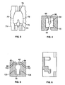
- FIG. 1 of the drawings is a vertical section of a reclosable fastener profile , partially broken away, showing male and female profiles, and guide ribs disposed on the outer walls of the reclosable bag.
- FIG. 2 of the drawings is a top view of a slider.
- FIG. 3 of the drawings is a bottom view of the slider.
- FIG. 4 of the drawings is a front cutaway view of the slider of FIGS. 2 and 3 showing a separator extending downwardly from the top surface thereof.
- FIG. 5 of the drawings is a rear cutaway view of the slider of FIGS. 2-4 .
- FIG. 6 of the drawings is a vertical section taken along FIG. 3 showing the internal configuration of the slider of FIGS. 2-5 .
- FIG. 7 of the drawings is a front perspective view of the reclosable container of FIG. 1 .
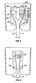
- FIG. 8 of the drawings is a vertical section of the male and female profiles of FIG. 1 extending from the bag walls, with the slider disposed on the fastener and held in place by the bottom track extending laterally from the bag walls, as well as the separator extending between the male and female profiles.
- FIG. 9 of the drawings is a vertical section of the bag and fastener strip of FIG. 10 showing in particular the male and female profiles interlocked and the slider affixed to the fastener strip by the bottom tracks.
- FIG. 10 is a perspective view of a reclosable container .
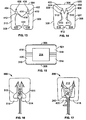
- FIG. 11 is a partial, cross-sectional view of exemplary fastener strips .
- FIG. 12 is a perspective view of an exemplary slider .
- FIG. 13 is a front elevation view of the exemplary slider of FIG. 12 .
- FIG. 14 is a rear elevation view of the exemplary slider of FIG. 12 .
- FIG. 15 is a bottom plan view of the exemplary slider of FIG. 12 .
- FIG. 16 is a partial, cross-section view of the exemplary fastener strips and the exemplary slider illustrating operation thereof.
- FIG. 17 is a partial, cross-section view of the exemplary fastener strips and the exemplary slider illustrating operation thereof in a partially open position.
- FIG. 18 is a partial, cross-section view of an alternative example of the reclosable fastener profiles of FIG. 1 showing male and female profiles and guide ribs disposed on the outer walls of the profiles.
- FIG. 19 is a vertical section of an embodiment of a container in accordance with the present invention showing in particular a cradle proximate the first end of the fastener strip which is sized, constructed and arranged to receive and retain the base of a slider when the slider is positioned at the first end of the fastener strip.
- a reclosable bag 10 having first and second walls 12 and 14 and an open top 16 is defined by first and second elongate flexible strips 18 and 20 attached to the first and second walls 12 and 14, respectively, adjacent the top 22 and 24 of the walls.
- One of the fastener strips 20 has a profile portion 26 which forms a groove 28.
- the other fastener strip 18 has a profile portion 30 forming a rib 32 with a portion of the rib 34 received and retained within the groove 28 when the bag 10 is closed.
- Each of the strips 18 and 20 has a base 38 and 48 connected to the respective walls 12 and 14 and each of the strips 18 and 20 further has an upper edge 42 and 44 adjacent the upper edge of the other strip 18 and 20, respectively.
- bag 10 has a slider 46 mounted on the strips 18 and 20 and moveable in one direction 48 longitudinally of the strips 18 to 20 to progressively separate the rib 32 from the groove 28 to open the bag 10.
- Slider 46 being moveable in the opposite direction 50, progressively returns the rib 32 portion to retain condition in the groove 28 to close the bag.
- the slider 46 further has a top 52.
- the slider 46 further has a separator 54 situated therein having a proximal portion 56 attached to the top 52 of the slider 46 and extending downwardly therefrom and having a distal portion 58 residing in a first space 70 between the top of the slider and the upper edges of the groove 28 when the rib portion 32 is retained in the groove 28 of the profile.
- the separator 54 has an arrow-shaped tip 60 constructed and arranged, i.e., positioned and sized to facilitate selective separation of the rib 32 from the groove 28.
- the separator has a length of 2.3 mm ⁇ .3 mm.
- the separator 54 is preferably integrally formed from the slider 46 and is made of one homogeneous unit of plastic, preferably injection molded POM ocetel rock or that sold by RTP Company, Winona, Minnesota, or polypropylene with additive for lubrication.
- the slider is constructed of polyethylene, polycarbonate, polystyrene, acryl nitryl butadiene styrene or other commonly formed injection molded plastic pieces.
- the outside walls 12, 14 have a pair of flanges 62 and 64 or tracks extending outwardly therefrom and running parallel to the upper edges 22, 24 of the walls.
- the flanges 62 and 64 are sized for telescopic reception in slider 46, as will be further described herein.
- slider 46 has a top portion 52. Extending downwardly from top portion 52, as is seen in FIG. 4 , is a separator 54 having a distal portion 58. The distal portion 58 of separator 54 has an arrowhead-shaped tip 60 mounted thereon. The arrowhead has an angle of 60° ⁇ 10° which is to facilitate opening of groove 28 of profile portion 26 with rib 32 profile portion 30 as contained therein.
- top portion 52 of slider 46 is approximately 1.2 mm in thickness.
- the distal portion 58 extends approximately 2.3 mm from the inside surface 66 of top 52.
- Slider 46 preferably has a height of approximately 8.6 mm, a thickness at its ends of 1.15 mm, a length of 14.8 mm, and the arrowhead-shaped tip 60 of a height of approximately 1 mm.
- slider 46 has a series of gripping ribs 68 which are vertically disposed along its lateral edges 71 and 72, respectively. These gripping ribs 68 in the preferred embodiment have a radius of approximately 1.25 mm.
- slider 46 has an interior chamber 70 having vertical walls at the front and rear ends 73 and 74, and having curved sidewalls 76 and 78 which have a radius of 9.9 mm.
- slider 46 has a centrally disposed gap 80.
- Gap 80 in the preferred embodiment is 1.15 mm in width.
- the left and right bottom surfaces 82 and 84 are approximately 2.5 mm in width having beveled surfaces 86 and 88.
- Beveled surfaces 86 and 88 are approximately 0.8 mm and are beveled at an angle of 45° relative to the left bottom surface 82 and right bottom surface 84.
- Gap 80 is designed to receive rib 32 and to retain rib 32 within chamber 70.
- chamber 70 is also designed to receive exterior flanges 62 and 64 which are retained within chamber 70 so as to retain slider 46 on fastener strips 18 and 20.
- a force of at least three pounds and preferably 5 pounds is required to remove slider 46 from fastener strips 18 and 20.
- slider 46 has a first travel and stop position 90 where the bag 10 is in the closed position and the fastener strips 18 and 20 are interlocked and a second travel and stop position 92 in which fastener strips 18 and 20 are separated from each other to allow dispensing of product from bag 10 or insertion of product therein.
- the proximal and distal ends 100 and 102 are fastener strips 18 and 20 and are ultrasonically sealed to each other and to bag walls 12 and 14, proximate the lateral edges 106 and 108 of bag 10.
- the ultrasonic seal is to prevent the fastener strips 18 and 20 from opening, and to prevent the bag 10 from being torn when the fastener strips 18 and 20 are open.
- slider 46 within slider 46 are inwardly facing channels 103 and 104, which are sized and positioned for slidable reception of flanges 62 and 64 and for retention of flanges 62 and 64 in slot or gap 80.
- On the bottom of slider 46 are a pair of inwardly facing shoulder members 110 and 112 with gap 80 therebetween. Shoulder members 110 and 112 have beveled surfaces 86 and 88 thereon for guiding fastener strips 18 and 20 into said gap 80.
- profile portion 26 has a groove 28.
- Groove 28 is formed from a pair of arms 28b and 28c of barbed members 34b and 44b extending inwardly and downwardly with a gap 28d extending therebetween sized for reception of male profile 32.
- Barbs 32b and 32c are sized, constructed, and arranged for interlocking with hooks 34b and 44b when male profile 32 is telescopically inserted into groove 28.
- Groove 28 and fastener 32 must be sufficiently flexible to allow barbs 32b and 32c, as well as fastener 32, to be inserted therein.
- arms 28b and 28c are sufficiently flexible to allow such insertion, but are sufficiently stiff to retain male fastener profile 32 within groove 28 when interlocked with barbs 32b and 32c.
- arms 28b and 28c are sufficiently flexible to allow such removal. It should be noted in this regard that barb 32 is larger in size and has a greater downward angle than barb 34b so as to make it more difficult for product within bag 10 to force fastener 16 open.
- flanges 62 and 64 are formed on the exterior walls of 12 and 14 of bag 10.
- Bag 10 of course, is formed from the thermoplastic film, which is extruded through a die.
- separator 54 has a length of 2.3 mm ⁇ .3 mm.
- Slider 46 has its proximal portion 56 of separator 54 attached to the top 52 of the interior surface of the slider 46 and has a distal portion 58 residing in a first space 70 within slider 46.
- the bag 200 comprises walls 202, 204 sealed along the lateral edges 202b, 202c of the walls 12, 14 to form an open-ended container.
- Materials commonly used in the art such as Linear Low Density Polyethylene (LLDPE), Low Density Polyethylene (LDPE), Nylon Polypropylene (PP), or Polyethylene Terepthalate (PET), may be used to form the walls 202, 204 with edges 205 and 205b.
- Complementary fastener strips 206, 208 in accordance with the present invention are mounted along upper edges of the walls 202, 204.
- the fastener strips 206, 208 are formed integrally with, and from the same material as, the walls 202, 204 through an extrusion process.
- the present invention is not limited in this regard and other techniques known to those having skill in the art may be employed to attach the fastener strips 206, 208 to their corresponding walls 202, 204.
- a slider 210 in accordance with the present invention preferably constructed of polyethylene, polycarbonate, polystyrene, acryl nitryl butadiene styrene or other materials commonly used in the fabrication of formed injection molded plastic pieces
- the slider 210 may slide in a first or opening direction 212 or, oppositely, in a second or closing direction 214 along a longitudinal length of the fastener strips 206, 208 as shown. Travel of the slider 210 along the fastener strips 206, 208 is limited at a proximal end 216 by a first stop position 218 and, at a distal end 220 by a second stop position 222.
- the stop positions 218, 222 are formed by fusing the fastener strips 206, 208 together using known techniques, such as ultrasonic sealing.
- each fastener strip 206, 208 comprises a base 230, 232 and a sealing member 234, 236 formed thereon, preferably in a continuous, integral fashion.
- each fastener strip 206, 208 is mounted on upper edge of a corresponding wall 302, 304 of the bag 200.
- the sealing members 234, 236 each comprise a plurality of complementary sealing portions 238, 240 that, when coupled together in an engaged condition (see FIG. 12 ), provide a substantially leak-proof seal for the bag 200.
- the sealing portions 238, 240 preferably have profiles that cause the sealing members 234, 236 to interlock when fully engaged with each other.
- the interdigitation of the complementary sealing portions 238, 240 when the sealing members 206, 208 are fully engaged provides multiple sealing points that substantially run along the entire longitudinal length of the fastener strips.
- profile 224 has two fastener strip 206, 208 that preferably comprise upward extending guide rails 226, 228.
- the guide rails 226, 228 serve to retain a slider on the fastener strips 206, 208.
- each guide rail 226, 228 preferably comprises a protrusion 230, 232.
- each protrusion 230, 232 comprises an outward-facing flange, although other configurations, such as an inward-facing flange, a combination of inward- and outward-facing flanges or a substantially circular profile could be equally employed.
- the present invention is not limited to a particular implementation of the guide rails 226, 228, and more conventional guide rail configurations (for example, along the opposite, outward-facing sides of the bases 230, 232) may be equally employed.
- one of the plurality of sealing portions 238 of a first sealing member 234 additionally comprises one or more finger members 242.
- the finger members 242 are illustrated as forming part of only one of the sealing portions 238 and of only the first sealing member 234, it is understood that additional finger members may be equally incorporated into other ones of the sealing portions 238 of the first sealing member 234, or additionally into one or more of the sealing portions 240 of the second sealing member 236.
- the one or more finger members 242 are incorporated into a lower-most sealing portion of the plurality of sealing portions 238.
- each finger member 242 preferably extends laterally and/or partially upwardly relative to the sealing portion in which it is formed.
- each finger member 242 preferably extends at a different angle relative to the others.
- the finger members 242 provide a sealing engagement with a complementary portion of the sealing member 236 of the second fastener strip 208 when the fastener strips 206, 208 are maintained in a partially engaged condition, i.e., at the point along the longitudinal length of the fastener strips 206, 208 where a separation 312 of the slider 300 causes the disengagement of the fastener strips 206, 208.
- the slider 300 comprises an elongated body 302 having a top wall 304 and sidewalls 306, 308 extending downwardly from the top wall 304.
- the sidewalls 306, 308 may extend substantially perpendicular to the top wall 604, they may also be angled relative to the top wall 304 and, in one embodiment of the present invention (as best illustrated in FIGS. 12-17 ), they are preferably tilted inward approximately 2 degrees from perpendicular relative to the top wall 304.
- a front wall 310 is provided and, likewise, a back wall 305 is provided at a distal end 303.
- the front and back walls 310, 305 are preferably (but not necessarily) substantially perpendicular to the top and sidewalls 304, 306, 308.
- the top wall 304 and sidewalls 306, 308 form an opening 314 ( FIG. 12 ) running along the entire length of the elongated body 302, thereby allowing passage of the fastener strips 206, 208 through the slider 300 as the slider traverses along the longitudinal length of the fastener strips 206, 208.
- the slider 300 further comprises substantially opposing, inward-facing flanges or rails 418, 420.
- the inward-facing flanges 418, 420 extend substantially perpendicularly relative to the sidewalls 306, 308, although this is not a requirement and other angles may be equally employed.
- the distal ends of the flanges 418, 420 define a gap 422 having dimensions such that the sealing members of the opposing fastener strips 206, 208, and particularly the sealing portion 238 having the at least one finger member 242 and its complementary sealing portion 240, are urged together to provide an additional degree of sealing, yet not completely interlocking, engagement, as best illustrated in FIG. 17 .
- the flanges 418, 420 may likewise be angled upwardly (relative to parallel with the top wall 304).
- the gap 422 is configured to be smaller than a combined width of the fastener strips 206, 208 when they are in a partially engaged condition.
- the inward-facing flanges 418, 420 are preferably formed within the front wall 310.
- an additional pair of inward-facing flanges 514, 516, defining therebetween another gap 512 are likewise disposed within the back wall 501.
- the additional inward-facing flanges 514, 516 are preferably affected by any angle of the sidewalls 306, 308 in a substantially identical manner as the first-mentioned inward-facing flanges 418, 420.
- the inward-facing flanges could run along the entire length of the elongated body 302 rather than being disposed solely within the end walls 310, 301 of the slider 300, although this is not presently preferred.
- each downward-facing channel 502, 504 is defined by side portions 306, 308 of separator 312 and by upper surfaces of grip rails 510, 512.
- the resulting of profiles 410, 412 of the downward facing channels 502, 504 substantially match the profiles of the corresponding guide rails 512, 510.
- the separator 312 comprises dimensions and is configured to induce separation of the sealing members 237, 239 of the corresponding fasteners strips 206, 208 without actually extending between sealing members 234, 236. As the slider 300 traverses the engaged fastener strips 206, 208, the separator block 312 causes the fastener strips 206, 208 to disengage, thereby opening the bag 200.
- the back wall 501 has formed therein additional downward-facing channels 502, 504 having profiles 506, 508 that substantially match the profiles of the guide rails 512, 510.
- additional grip rails 810, 812 are provided to engage the protrusions 520, 522 of the guide rails 510, 512 thereby retaining the slider 300 on the fastener strips 206, 208.
- the back wall 501 comprises closing gates 511, 513 configured such that the space provided between the closing gates 511, 513 forces together the sealing portions 234 of the first fastener strip 206 and the complementary sealing portions 236 of the second fastener strip 208 (see FIG. 16 ), thereby establishing an interlocking, engaged condition between the fastener strips 206, 208 and providing a substantially leak-proof seal.
- FIGS. 16 and 17 operation of the slider 300 in conjunction with the fastener strips 206, 208 is further illustrated.
- the closing gates 511, 513 cause the complementary sealing portions of the sealing members 234, 236 to engage in an interlocking fashion as shown.
- the inward facing flanges 514, 516 provide substantially no aid in retaining the slider 300 on the fastener strips 206, 208.
- the separator 312 causes the plurality of complementary sealing portions 238, 240 of the sealing members 234, 236 to disengage, thereby opening the bag. Note that, at the position of the slider 300 along the fastener strips 206, 208, particularly the position of the separator 312, the sealing members 234, 236 are maintained in a partially engaged condition that, in prior art devices, would cause leaks at that location.
- the configuration of the inward-facing flanges 418, 420 and the resulting gap 422 defined therebetween causes the one or more finger members 242 to engage a corresponding portion of the opposing sealing member, thereby providing additional leak resistance at the point of the slider 300 along the fastener strips 206, 208.
- the fastener strip and reclosable bag 600 are disclosed having first and second walls 602 and 604 and an open top 606 defined by first and second elongate flexible fastener strips 608 and 610 attached to the first and second walls 602 and 604, respectively. Adjacent the top of the walls one of the fastener strips 608 has a groove 612 formed therein and the other fastener strip 610 has a rib 614, substantially similar to the rib previously shown in FIGS. 1-5 . A portion of the rib 614 is received and retained within the groove 612 when the bag top 606 is closed.
- Each of the fastener strips 608 and 610 has a base 616 and 618, respectively, shown in FIG. 18 and similarly in FIG.
- Each of the fastener strips 608 and 610 has an upper edge 620 and 622, respectively, with a slider shown in FIG. 3 .
- the slider 300b is moveable in a first longitudinal direction 624 to progressively separate the rib 614 from the groove 608 to open the bag.
- the slider 300b is moveable in the opposite direction 626 to progressively return the rib 614 to a retained condition in the groove 612 to close the bag 600.
- a cradle 628 is provided proximate one end 630 of the fastener strip.
- the cradle 628 is sized, constructed and arranged to receive the base 632 of the slider 600 therein while the fastener strip 608 is sealingly engaged with the corresponding sealing portion 634 of the complementary sealing member, i.e., the rib 614.
- the cradle 628 has a length greater than the length of the slider so as to retain the slider 600 within the cradle 628.
- the cradle 628 has a tab 636 extending at an angle of approximately 45° therefrom for abutment against and retention of the slider 600 within the cradle 628.
- the cradle is substantially C-shaped so as to retain the slider therein.
- C-shaped it is meant that it has a recessed interior and at least one tab extending therefrom at an angle of 15-30° so as to abut against the slider and retain the slider within the cradle.
- a curved lip 638 On the opposite side from the tab 636 is a curved lip 638 for abutting against the slider 600 therein.
- the end portion of the fastener strips has a spot seal section 640 in which the fastener strips are ultrasonically or heat-sealed together so that the ends of the bag and the ends of the fastener strips will not leak.
- cradle 628 has a length of 9.78 mm and a depth of 3.35 mm.
- the base of the cradle is approximately 2.03 mm. All of these dimensions are, of course, subject to variation in manufacture of up to .25 mm.
- the cradle tip has a radius of 0.07 mm as to allow easier passage of the slider 300b thereover.
Landscapes
- Engineering & Computer Science (AREA)
- Mechanical Engineering (AREA)
- Slide Fasteners (AREA)
- Bag Frames (AREA)
Applications Claiming Priority (2)
| Application Number | Priority Date | Filing Date | Title |
|---|---|---|---|
| US11/627,148 US8714819B2 (en) | 2005-10-31 | 2007-01-25 | Reclosable fastener |
| PCT/US2008/052120 WO2008092123A2 (en) | 2007-01-25 | 2008-01-25 | Improved reclosable container |
Publications (3)
| Publication Number | Publication Date |
|---|---|
| EP2106368A2 EP2106368A2 (en) | 2009-10-07 |
| EP2106368A4 EP2106368A4 (en) | 2011-11-02 |
| EP2106368B1 true EP2106368B1 (en) | 2012-12-05 |
Family
ID=39645518
Family Applications (1)
| Application Number | Title | Priority Date | Filing Date |
|---|---|---|---|
| EP08728343A Not-in-force EP2106368B1 (en) | 2007-01-25 | 2008-01-25 | Improved reclosable container |
Country Status (10)
| Country | Link |
|---|---|
| US (1) | US8714819B2 (enExample) |
| EP (1) | EP2106368B1 (enExample) |
| JP (2) | JP5410298B2 (enExample) |
| CN (3) | CN104129555B (enExample) |
| AU (1) | AU2008207793B2 (enExample) |
| BR (1) | BRPI0806236B1 (enExample) |
| CA (1) | CA2671886C (enExample) |
| ES (1) | ES2401074T3 (enExample) |
| RU (1) | RU2470844C2 (enExample) |
| WO (1) | WO2008092123A2 (enExample) |
Families Citing this family (15)
| Publication number | Priority date | Publication date | Assignee | Title |
|---|---|---|---|---|
| US20070180668A1 (en) * | 2006-02-08 | 2007-08-09 | Ackerman Bryan L | Pouch with slider and grip members |
| US8714819B2 (en) | 2005-10-31 | 2014-05-06 | Global Packaging Solutions Limited | Reclosable fastener |
| US8096022B2 (en) * | 2005-10-31 | 2012-01-17 | Global Packaging Solutions Limited | Reclosable container and method of manufacture |
| US20100296756A1 (en) * | 2008-01-22 | 2010-11-25 | S2F Flexico | Bag including closure profiles actuated by a slider |
| US8087826B1 (en) | 2010-06-25 | 2012-01-03 | Pactiv Corporation | Slider track with improved seal strength |
| CN102894551B (zh) * | 2012-11-02 | 2015-08-05 | 宋致选 | 拉链组件及设置该拉链组件的保鲜袋 |
| WO2015109233A1 (en) | 2014-01-17 | 2015-07-23 | BlueAvocado, Co. | Washable, waterproof, sealable and reusable soft gusseted volumized storage bags |
| US9878828B2 (en) | 2014-06-20 | 2018-01-30 | S. C. Johnson & Son, Inc. | Slider bag with a detent |
| CN107074405A (zh) * | 2014-10-17 | 2017-08-18 | 斯蒂芬·G.·阿姆斯特朗 | 用于袋的具有滑动件的闭合件 |
| WO2016204812A1 (en) * | 2015-06-19 | 2016-12-22 | S.C. Johnson & Son, Inc. | Slider bag with a detent |
| US10215281B2 (en) * | 2016-05-04 | 2019-02-26 | The Boeing Company | Seal assembly for sealing relatively movable components |
| CN107865491A (zh) * | 2017-12-21 | 2018-04-03 | 开易(广东)服装配件有限公司 | 滑脱拉链及其所应用的制品 |
| CN108438491A (zh) * | 2018-03-01 | 2018-08-24 | 北京优宠时光商贸有限公司 | 一种便于使用的包装袋自封装置 |
| CN108575674A (zh) * | 2018-06-25 | 2018-09-28 | 中国农业科学院农田灌溉研究所 | 一种灌溉用滑动式连续取水软带 |
| CN109229826B (zh) * | 2018-08-22 | 2024-02-27 | 德清尚邑塑料制品有限公司 | 一种用于包装袋的骨条结构以及包装袋 |
Family Cites Families (142)
| Publication number | Priority date | Publication date | Assignee | Title |
|---|---|---|---|---|
| US2048692A (en) * | 1934-04-11 | 1936-07-28 | Hydraulic Brake Co | Parking brake for trailers |
| US2581604A (en) | 1946-04-17 | 1952-01-08 | Nat Organ Supply Company | Slide fastener |
| US3054434A (en) | 1960-05-02 | 1962-09-18 | Ausnit | Bag closure |
| US3122807A (en) | 1960-07-22 | 1964-03-03 | Edgar M Ausnit | Slider for a pouch and the like |
| US3230593A (en) | 1962-07-26 | 1966-01-25 | Flexigrip Inc | Slide fastener for profiled strips |
| US3173184A (en) | 1962-09-21 | 1965-03-16 | Ausnit Steven | Shaped head top closure |
| US3338284A (en) | 1963-07-22 | 1967-08-29 | Ausnit Steven | Sheet with fastener structure |
| US3220076A (en) | 1963-09-20 | 1965-11-30 | Flexigrip Inc | Slide fastener |
| US3259951A (en) | 1964-07-15 | 1966-07-12 | Merle A Zimmerman | Slide fastener |
| US3713923A (en) | 1968-02-26 | 1973-01-30 | Minigrip Inc | Method of assembling slider with a profiled strip separable fastener |
| US3565147A (en) * | 1968-11-27 | 1971-02-23 | Steven Ausnit | Plastic bag having reinforced closure |
| US3852386A (en) | 1970-12-21 | 1974-12-03 | Dow Chemical Co | Manufacture of film having formed fastener means therein |
| EP0004707B1 (en) | 1978-03-09 | 1981-12-02 | Bud, Hans | Sliding clasp for mating strips and method for mounting said sliding clasp on said mating strips |
| US4663915A (en) | 1983-10-31 | 1987-05-12 | Signode Corporation | Method of packaging and apparatus |
| US4620320A (en) | 1984-12-20 | 1986-10-28 | Kcl Corporation | Substantially leakproof zipper closure for bags and method |
| US4710968A (en) | 1985-09-11 | 1987-12-01 | First Brands Corporation | Trident interlocking closure profile configuration |
| US4778282A (en) | 1985-09-11 | 1988-10-18 | First Brands Corporation | Trident interlocking closure profile configuration |
| FR2589437B1 (fr) * | 1985-11-04 | 1988-06-10 | Flexico France Sarl | Dispositif de liaison entre deux feuilles de matiere plastique; sac equipe, pour sa fermeture, d'un tel dispositif |
| US4819309A (en) | 1987-08-27 | 1989-04-11 | Minnesota Mining And Manufacturing Company | Fastener with parts having projecting engaging portions |
| US4846585A (en) | 1988-01-29 | 1989-07-11 | Minigrip, Inc. | Easy open bag structure |
| US5020194A (en) | 1990-03-07 | 1991-06-04 | Mobil Oil Corporation | Leakproof zipper with slider |
| US5007143A (en) | 1990-03-07 | 1991-04-16 | Mobil Oil Corp. | Rolling action zipper profile and slipper therefor |
| US5048692A (en) | 1990-04-03 | 1991-09-17 | Colgate-Palmolive Company | Bag closure structure in which a single resealable closure acts as both the primary and secondary closures |
| US5272794A (en) | 1990-11-20 | 1993-12-28 | Yoshida Kogyo K.K. | Flexible closure device |
| US5131121A (en) | 1991-03-22 | 1992-07-21 | Mobil Oil Corporation | Protruding end stops for plastic reclosable fastener |
| US5067208A (en) | 1991-03-22 | 1991-11-26 | Mobil Oil Corporation | Plastic reclosable fastener with self-locking slider |
| US5189764A (en) * | 1991-03-22 | 1993-03-02 | Mobil Oil Corporation | Plastic reclosable fastener with structure for retaining slider in closed position |
| US5351369A (en) | 1992-06-16 | 1994-10-04 | Illinois Tool Works, Inc. | Moisture-resistant fastener |
| US5301395A (en) * | 1993-07-29 | 1994-04-12 | Mobil Oil Corporation | Plastic reclosable fastener with structure for restraining slider in closed position and for facilitating reopening fastener |
| US5405478A (en) | 1993-11-22 | 1995-04-11 | Mobil Oil Corporation | Tubular plastic end stops bonded to plastic zipper |
| US5442838A (en) | 1994-06-17 | 1995-08-22 | Mobil Oil Corporation | Rolling action zipper profile and slider |
| US5442837A (en) | 1994-06-20 | 1995-08-22 | Mobil Oil Corporation | Integrated end stops for zipper slider |
| US5647100A (en) | 1995-03-14 | 1997-07-15 | Dowbrands L.P. | Closure member for a reclosable thermoplastic bag |
| JP2938784B2 (ja) | 1995-05-30 | 1999-08-25 | 昭和高分子株式会社 | プラスチックチャック |
| GB2307295B (en) | 1995-11-17 | 1997-10-29 | Pierre Robert Graves | Transcutaneous measurement of substance in body tissues or fluid |
| US5664296A (en) | 1996-06-26 | 1997-09-09 | Reynolds Consumer Products Inc. | Closure arrangement having a reclosable seal |
| US5924173A (en) | 1996-08-16 | 1999-07-20 | Tenneco Packaging | End posts for plastic zipper |
| US5664299A (en) | 1996-09-10 | 1997-09-09 | Dowbrands L.P. | Reclosable fastener assembly |
| US5836056A (en) * | 1996-09-10 | 1998-11-17 | S. C. Johnson Home Storage Inc. | Reclosable fastener assembly |
| US5871281A (en) | 1996-11-25 | 1999-02-16 | Kcl Corporation | Zipper slider pivoting wedge |
| FR2761956B1 (fr) * | 1997-04-10 | 1999-06-25 | Flexico France Sarl | Sachet comportant des profiles de fermeture complementaires actionnes par curseur |
| US5950285A (en) | 1997-08-29 | 1999-09-14 | S. C. Johnson Home Storage Inc. | Endstop and docking means for thermoplastic bags |
| US5956815A (en) | 1997-05-19 | 1999-09-28 | Kcl Corporation | Slider zipper recloseable fastener |
| FR2770493B1 (fr) | 1997-11-06 | 2000-02-04 | Flexico France Sarl | Dispositif de fermeture a profiles pour sac de conditionnement |
| US5956924A (en) | 1997-11-07 | 1999-09-28 | Rcl Corporation | Method and apparatus for placing a product in a flexible recloseable container |
| US6216423B1 (en) * | 1997-11-07 | 2001-04-17 | Huntsman Kcl Corporation | Method and apparatus for placing a product in a flexible recloseable container |
| FR2775953B1 (fr) | 1998-03-10 | 2000-06-02 | Flexico France Sarl | Procede et machine de formation de sachets avec fermeture a profiles transversaux |
| US6820395B2 (en) | 1999-04-15 | 2004-11-23 | Illinois Tool Works Inc. | Process and apparatus for forming packaging bags with a fastener |
| US6694704B1 (en) | 1998-04-20 | 2004-02-24 | Illinois Tool Works Inc. | Process and apparatus for forming packaging bags with a fastener |
| KR100566336B1 (ko) | 1998-06-04 | 2006-03-31 | 가오가부시끼가이샤 | 폴리머 에멀젼 및 그 제조법 |
| US6178722B1 (en) | 1998-06-08 | 2001-01-30 | Illinois Tool Works, Inc. | Application system for sliders at form-fill-seal machine |
| US6609353B1 (en) | 1998-06-08 | 2003-08-26 | Illinois Tool Works Inc. | Application system for sliders at form-fill-seal machine |
| FR2780037B1 (fr) | 1998-06-17 | 2000-09-08 | Flexico France Sarl | Sachet comprenant des profiles de fermeture complementaires actionnes par curseur |
| US6195762B1 (en) * | 1998-06-24 | 2001-02-27 | Micron Techonology, Inc. | Circuit and method for masking a dormant memory cell |
| US8002467B2 (en) | 1999-10-12 | 2011-08-23 | Com-Pac International, Inc. | Reclosable fastener profile seal and method of forming a fastener profile assembly |
| FR2785259B1 (fr) | 1998-11-02 | 2001-12-07 | Flexico France Sarl | Sachet comprenant des profiles de fermeture complementaires actionnes par curseur |
| US6047450A (en) | 1999-02-09 | 2000-04-11 | Illinois Tool Works Inc. | Slide zipper assembly |
| US6287001B1 (en) | 1999-05-07 | 2001-09-11 | Reynolds Consumer Products, Inc. | Closure arrangement having interlocking closure profiles, slider device, and systems and methods for retaining slider device |
| US6292986B1 (en) | 1999-05-10 | 2001-09-25 | Alexander R. Provan | Assembly and accumulation of sliders for profiled zippers |
| US6286999B1 (en) | 1999-05-11 | 2001-09-11 | Pactiv Corporation | Tamper-evident reclosable bag |
| US6571430B1 (en) | 1999-06-10 | 2003-06-03 | The Glad Products Company | Closure device |
| US6575628B1 (en) * | 1999-06-10 | 2003-06-10 | The Glad Products | Closure device |
| US6595689B1 (en) | 1999-06-10 | 2003-07-22 | The Glad Products Company | Closure device |
| US6581249B1 (en) | 1999-06-10 | 2003-06-24 | The Glad Products Company | Closure device |
| US20060120630A9 (en) * | 1999-06-17 | 2006-06-08 | Steven Ausnit | Watertight slider-zipper assembly for reclosable packaging |
| US6217215B1 (en) | 1999-07-07 | 2001-04-17 | Reynolds Consumer Products, Inc. | Closure mechanism having a perceptible feedback system |
| US6477820B1 (en) | 1999-07-29 | 2002-11-12 | Kraft Foods Holdings, Inc. | Method of making a package with a zipper closure |
| US7041249B2 (en) | 1999-10-12 | 2006-05-09 | Com-Pac International | Vibratory molding process and product |
| JP2001130594A (ja) | 1999-11-08 | 2001-05-15 | Showa Highpolymer Co Ltd | スライダー付きプラスチックチャック及び該プラスチックチャックを備えた袋体並びにその袋体の製造方法 |
| JP2001315806A (ja) | 2000-03-01 | 2001-11-13 | Reynolds Consumer Prod Inc | シーラント層と剥離シールを有する再閉止可能ジッパー、パッケージ、および方法 |
| US7467893B2 (en) | 2000-03-14 | 2008-12-23 | Com-Pac International, Inc. | Reclosable plastic bag |
| US6576278B1 (en) | 2000-03-14 | 2003-06-10 | Com-Pac International, Inc. | Reclosable baby bottle liner and baby bottle having reclosable liner |
| US6954969B1 (en) | 2000-03-14 | 2005-10-18 | Com-Pac International, Inc. | Reclosable fastener strip |
| JP3644869B2 (ja) | 2000-04-10 | 2005-05-11 | 株式会社愛知商会 | チャック及びチャック付きプラスチック包装袋 |
| US6461042B1 (en) | 2000-05-01 | 2002-10-08 | Reynolds Consumer Products, Inc. | Resealable closure mechanism having a slider device |
| US6386760B1 (en) | 2000-06-12 | 2002-05-14 | Reynolds Consumer Products, Inc. | Slider reclosable bags with dual tamper-evident features |
| US6385818B1 (en) | 2000-07-10 | 2002-05-14 | The Glad Products Company | End stop and slider for reclosable fastener |
| GB0016894D0 (en) | 2000-07-11 | 2000-08-30 | Supreme Plastics Group Ltd | Reclosable fasteners for plastics bags and other containers |
| EP1305227B1 (en) * | 2000-07-31 | 2007-04-25 | Reynolds Consumer Products, Inc. | Slider device, package, and method of mounting |
| US6470551B1 (en) | 2000-08-10 | 2002-10-29 | Pactiv Corporation | Method of making a fasteners arrangement with notches at spaced preseals |
| US6562165B1 (en) | 2000-08-15 | 2003-05-13 | S.C. Johnson Home Storage, Inc. | Method for laminating closure member to film web |
| EP1315429B1 (de) | 2000-09-08 | 2007-07-04 | Zip Pack Ip Ag | Reissverschluss für beutel und säcke |
| US6679027B2 (en) * | 2000-11-29 | 2004-01-20 | Reynolds Consumer Products, Inc. | Resealable closure mechanism having a slider device and methods |
| JP4559615B2 (ja) | 2000-12-11 | 2010-10-13 | ハイパック株式会社 | 不正開封を防止したスライダー付きプラスチックチャック及び該チャック付き袋体 |
| US7017240B2 (en) | 2001-02-08 | 2006-03-28 | The Glad Products Company | Closure device |
| KR100945342B1 (ko) | 2001-04-30 | 2010-03-08 | 밀람 미이거 벤 | 직물의 실링장치 |
| US6390676B1 (en) | 2001-05-15 | 2002-05-21 | Honeywell International Inc. | Reclosable package using straight tear film and process for manufacture |
| US6594872B2 (en) | 2001-08-17 | 2003-07-22 | The Glad Products Company | Interlocking closure device |
| US7270479B2 (en) | 2001-08-24 | 2007-09-18 | S.C. Johnson Home Storage, Inc. | Venting reclosable bags |
| US6692147B2 (en) | 2001-08-24 | 2004-02-17 | Charles Nelson | Venting reclosable bags |
| DE60140771D1 (de) | 2001-09-04 | 2010-01-21 | Hipack Co Ltd | Kunststoffreissverschluss mit schieber und beutel mit kunststoffreissverschluss |
| US6581253B2 (en) | 2001-09-14 | 2003-06-24 | Erkenbrack Kenneth Beresford | Fluid-tight container seal |
| US6901637B2 (en) | 2001-10-03 | 2005-06-07 | Illinois Tool Works Inc. | Zipper with pre-activated peel-seal |
| US7313846B2 (en) * | 2001-10-17 | 2008-01-01 | Illinois Tool Works, Inc. | Sliders for reclosable containers |
| US6739755B2 (en) | 2001-10-24 | 2004-05-25 | Reynolds Consumer Products, Inc. | Leak proof closure mechanism for resealable bag |
| US6810641B2 (en) | 2001-11-13 | 2004-11-02 | Illinois Tool Works, Inc. | Method and apparatus for forming double zipper bags |
| US20030101552A1 (en) | 2001-11-30 | 2003-06-05 | Plourde Eric P. | Variable alignment zipper for reclosable bags |
| US7159282B2 (en) | 2002-03-01 | 2007-01-09 | Pactiv Corporation | Reclosable fasteners or zippers for use with polymeric bags |
| US6691383B2 (en) | 2002-03-07 | 2004-02-17 | Illinois Tool Works Inc. | Webless zipper |
| US20030223654A1 (en) | 2002-05-31 | 2003-12-04 | Gerrits Robert P. | Liquid tight closure mechanism |
| US6698925B2 (en) | 2002-06-13 | 2004-03-02 | Illinois Tool Works Inc. | Reclosable packaging having zipper with means for maintaining closure |
| US6932509B2 (en) | 2002-06-28 | 2005-08-23 | S. C. Johnson Home Storage, Inc. | Recloseable storage bag with secondary closure members |
| US6854886B2 (en) | 2002-06-28 | 2005-02-15 | Illinois Tool Works Inc. | Watertight closure for a reclosable package |
| US6846107B2 (en) | 2002-07-19 | 2005-01-25 | Cti Industries Corporation | Glue drop end stops for zippered bag |
| US6981936B2 (en) | 2002-08-05 | 2006-01-03 | Illinois Tool Works Inc. | Method for making slider end stops on zippers for reclosable packaging |
| US6846108B2 (en) * | 2002-08-20 | 2005-01-25 | Reynolds Consumer Products, Inc. | Resealable package having zipper closure including a slider device and retaining notch |
| US6854887B2 (en) | 2002-08-20 | 2005-02-15 | Cti Industries Corporation | Slider with arm |
| JP2004083068A (ja) | 2002-08-27 | 2004-03-18 | Showa Highpolymer Co Ltd | スライダー付きプラスチックチャックを備えた袋体 |
| US20040066984A1 (en) | 2002-10-04 | 2004-04-08 | Yi Li Jenny Jie | Built-in zipper bag and manufacturing method thereof |
| US7267856B2 (en) * | 2002-10-07 | 2007-09-11 | Pactiv Corporation | Ultrasonic end stops on zipper closure bags and methods for making same |
| US7016790B2 (en) * | 2002-10-23 | 2006-03-21 | Taiwan Semiconductor Manufacturing Co., Ltd. | In-line hot-wire sensor for slurry monitoring |
| US6817763B2 (en) | 2002-10-30 | 2004-11-16 | Reynolds Consumer Products, Inc. | Leak-proof package design including reclosable zipper having slider including a full-length plow |
| US7305742B2 (en) | 2002-11-13 | 2007-12-11 | Cti Industries Corporation | Seal for zippered bag |
| JP4234415B2 (ja) | 2002-12-17 | 2009-03-04 | 東ショウパック株式会社 | スライダー付きプラスチックチャックおよびチャック付き袋体 |
| US6862866B2 (en) | 2002-12-31 | 2005-03-08 | Protoco Engineering, Inc. | Automatic reclosable bag filler |
| US7189001B2 (en) | 2003-01-02 | 2007-03-13 | Reynolds Consumer Products, Inc. | Liquid tight locking arrangement with sealing fingers |
| US6951421B2 (en) | 2003-02-14 | 2005-10-04 | Illinois Tool Works Inc. | Reclosable packaging having slider-operated string zipper |
| US7036988B2 (en) | 2003-02-19 | 2006-05-02 | Illinois Tool Works Inc. | Zipper for vacuum storage bag |
| US7097359B2 (en) | 2003-02-20 | 2006-08-29 | Illinois Tool Works Inc. | Reclosable packaging having slider coupled to top of zipper |
| US6948848B2 (en) | 2003-03-27 | 2005-09-27 | Illinois Tool Works Inc. | Reclosable packaging having slider-operated string zipper |
| WO2004103827A2 (en) | 2003-05-19 | 2004-12-02 | S. C. Johnson Home Storage, Inc. | Closure device for a reclosable pouch |
| US7052181B2 (en) * | 2003-06-11 | 2006-05-30 | S.C. Johnson Home Storage, Inc. | Zippered bag having a pair of fastener strips |
| US7416336B2 (en) | 2003-07-10 | 2008-08-26 | Illinois Tool Works Inc. | Tamper-evident slider-actuated string-zippered bag and related method of manufacture |
| US20050008266A1 (en) | 2003-07-10 | 2005-01-13 | Crunkleton Gregory H. | Reclosable package having internal seal made of double-sided adhesive tape |
| US6964519B2 (en) | 2003-07-30 | 2005-11-15 | Erkenbrack Kenneth Beresford | Atmospheric and/or differential pressure closure for an evacuable storage container |
| US7611283B2 (en) | 2003-09-11 | 2009-11-03 | Cti Industries, Inc. | Airtight zipper |
| US7223017B2 (en) | 2003-12-19 | 2007-05-29 | Sonoco Development, Inc. | Side gusset bag with reclose feature |
| US7565977B2 (en) | 2004-02-13 | 2009-07-28 | Leonard Frenkil | Sealable bag with excess air evacuation blocking structure |
| US7583269B2 (en) * | 2004-02-17 | 2009-09-01 | Sun Microsystems, Inc. | Window system 2D graphics redirection using direct texture rendering |
| US20050207679A1 (en) | 2004-03-19 | 2005-09-22 | Armstrong Stephen G | Reclosable bag |
| JP2005289452A (ja) | 2004-03-31 | 2005-10-20 | Aichi Shokai:Kk | 液体用袋 |
| US7416338B2 (en) * | 2004-06-18 | 2008-08-26 | Illinois Tool Works Inc. | Reclosable package having zipper with hinged flap and related methods of manufacture |
| JP2006076619A (ja) | 2004-09-10 | 2006-03-23 | Showa Highpolymer Co Ltd | スライダーチャック付き包装袋 |
| EP1802213B1 (en) | 2004-10-11 | 2015-08-26 | Ashok Chaturvedi | A leak proof re-closable flexible pouch |
| US20080196321A1 (en) * | 2007-02-16 | 2008-08-21 | Aaron Kronemeyer | Drip edge system |
| US8419277B2 (en) | 2005-01-28 | 2013-04-16 | Illinois Tool Works Inc. | Easy open slider package |
| US20060171610A1 (en) * | 2005-01-31 | 2006-08-03 | Buchman James E | Internal gripping slider and method |
| US7162779B2 (en) | 2005-02-16 | 2007-01-16 | Illinois Tool Works Inc. | Water-resistant zipper with slider |
| US8096022B2 (en) | 2005-10-31 | 2012-01-17 | Global Packaging Solutions Limited | Reclosable container and method of manufacture |
| US8714819B2 (en) | 2005-10-31 | 2014-05-06 | Global Packaging Solutions Limited | Reclosable fastener |
| US8256959B2 (en) | 2006-06-14 | 2012-09-04 | Global Packaging Solutions Limited | Fastener strip, slider and reclosable container comprising same |
| US7587786B2 (en) * | 2005-11-03 | 2009-09-15 | The Scott Fetzer Company | Vacuum cleaner with removable handle |
-
2007
- 2007-01-25 US US11/627,148 patent/US8714819B2/en active Active
-
2008
- 2008-01-25 EP EP08728343A patent/EP2106368B1/en not_active Not-in-force
- 2008-01-25 AU AU2008207793A patent/AU2008207793B2/en not_active Ceased
- 2008-01-25 RU RU2009126151/12A patent/RU2470844C2/ru not_active IP Right Cessation
- 2008-01-25 WO PCT/US2008/052120 patent/WO2008092123A2/en not_active Ceased
- 2008-01-25 CA CA2671886A patent/CA2671886C/en active Active
- 2008-01-25 CN CN201410333365.6A patent/CN104129555B/zh not_active Expired - Fee Related
- 2008-01-25 CN CN201110279108.5A patent/CN102582922B/zh not_active Expired - Fee Related
- 2008-01-25 BR BRPI0806236A patent/BRPI0806236B1/pt not_active IP Right Cessation
- 2008-01-25 JP JP2009547445A patent/JP5410298B2/ja not_active Expired - Fee Related
- 2008-01-25 CN CN2008800015828A patent/CN101595040B/zh not_active Expired - Fee Related
- 2008-01-25 ES ES08728343T patent/ES2401074T3/es active Active
-
2013
- 2013-01-29 JP JP2013014842A patent/JP2013136415A/ja active Pending
Also Published As
| Publication number | Publication date |
|---|---|
| RU2009126151A (ru) | 2011-02-27 |
| HK1170460A1 (en) | 2013-03-01 |
| WO2008092123A3 (en) | 2008-12-18 |
| US8714819B2 (en) | 2014-05-06 |
| JP5410298B2 (ja) | 2014-02-05 |
| HK1202505A1 (en) | 2015-10-02 |
| JP2010516578A (ja) | 2010-05-20 |
| AU2008207793B2 (en) | 2013-10-10 |
| ES2401074T3 (es) | 2013-04-16 |
| CN104129555A (zh) | 2014-11-05 |
| WO2008092123A4 (en) | 2009-02-19 |
| CN101595040B (zh) | 2011-11-30 |
| CN102582922A (zh) | 2012-07-18 |
| BRPI0806236A2 (pt) | 2011-09-06 |
| RU2470844C2 (ru) | 2012-12-27 |
| CN101595040A (zh) | 2009-12-02 |
| EP2106368A2 (en) | 2009-10-07 |
| HK1135951A1 (en) | 2010-06-18 |
| EP2106368A4 (en) | 2011-11-02 |
| CA2671886A1 (en) | 2008-07-31 |
| CA2671886C (en) | 2016-01-19 |
| CN104129555B (zh) | 2018-12-07 |
| AU2008207793A1 (en) | 2008-07-31 |
| CN102582922B (zh) | 2014-08-06 |
| JP2013136415A (ja) | 2013-07-11 |
| US20070116387A1 (en) | 2007-05-24 |
| BRPI0806236B1 (pt) | 2018-09-11 |
| WO2008092123A2 (en) | 2008-07-31 |
Similar Documents
| Publication | Publication Date | Title |
|---|---|---|
| EP2106368B1 (en) | Improved reclosable container | |
| EP2040989B1 (en) | Fastener strip, slider and reclosable container comprising same | |
| EP2292522B1 (en) | Reclosable fasteners or zippers for use with polymeric bags | |
| US20120087602A1 (en) | Reclosable container and method of manufacture | |
| US10640262B2 (en) | Reclosable airtight container and method of manufacture | |
| HK1135951B (en) | Improved reclosable container | |
| AU2014200133A1 (en) | Improved reclosable container | |
| US20170190477A1 (en) | Reclosable container and method of manufacture | |
| HK1170460B (en) | A bag closure assembly | |
| HK1202505B (zh) | 袋子闭合组件 | |
| HK1134476B (en) | Fastener strip, slider and reclosable container comprising same | |
| HK1179590B (en) | Fastener strip, slider and reclosable container comprising same |
Legal Events
| Date | Code | Title | Description |
|---|---|---|---|
| PUAI | Public reference made under article 153(3) epc to a published international application that has entered the european phase |
Free format text: ORIGINAL CODE: 0009012 |
|
| 17P | Request for examination filed |
Effective date: 20090603 |
|
| AK | Designated contracting states |
Kind code of ref document: A2 Designated state(s): AT BE BG CH CY CZ DE DK EE ES FI FR GB GR HR HU IE IS IT LI LT LU LV MC MT NL NO PL PT RO SE SI SK TR |
|
| DAX | Request for extension of the european patent (deleted) | ||
| REG | Reference to a national code |
Ref country code: HK Ref legal event code: DE Ref document number: 1135951 Country of ref document: HK |
|
| A4 | Supplementary search report drawn up and despatched |
Effective date: 20111006 |
|
| RIC1 | Information provided on ipc code assigned before grant |
Ipc: B65D 33/16 20060101AFI20110929BHEP |
|
| GRAP | Despatch of communication of intention to grant a patent |
Free format text: ORIGINAL CODE: EPIDOSNIGR1 |
|
| GRAS | Grant fee paid |
Free format text: ORIGINAL CODE: EPIDOSNIGR3 |
|
| GRAA | (expected) grant |
Free format text: ORIGINAL CODE: 0009210 |
|
| AK | Designated contracting states |
Kind code of ref document: B1 Designated state(s): AT BE BG CH CY CZ DE DK EE ES FI FR GB GR HR HU IE IS IT LI LT LU LV MC MT NL NO PL PT RO SE SI SK TR |
|
| REG | Reference to a national code |
Ref country code: GB Ref legal event code: FG4D |
|
| REG | Reference to a national code |
Ref country code: CH Ref legal event code: EP |
|
| REG | Reference to a national code |
Ref country code: AT Ref legal event code: REF Ref document number: 587146 Country of ref document: AT Kind code of ref document: T Effective date: 20121215 |
|
| REG | Reference to a national code |
Ref country code: IE Ref legal event code: FG4D |
|
| REG | Reference to a national code |
Ref country code: DE Ref legal event code: R096 Ref document number: 602008020597 Country of ref document: DE Effective date: 20130131 |
|
| REG | Reference to a national code |
Ref country code: AT Ref legal event code: MK05 Ref document number: 587146 Country of ref document: AT Kind code of ref document: T Effective date: 20121205 |
|
| REG | Reference to a national code |
Ref country code: ES Ref legal event code: FG2A Ref document number: 2401074 Country of ref document: ES Kind code of ref document: T3 Effective date: 20130416 |
|
| PG25 | Lapsed in a contracting state [announced via postgrant information from national office to epo] |
Ref country code: NO Free format text: LAPSE BECAUSE OF FAILURE TO SUBMIT A TRANSLATION OF THE DESCRIPTION OR TO PAY THE FEE WITHIN THE PRESCRIBED TIME-LIMIT Effective date: 20130305 Ref country code: LT Free format text: LAPSE BECAUSE OF FAILURE TO SUBMIT A TRANSLATION OF THE DESCRIPTION OR TO PAY THE FEE WITHIN THE PRESCRIBED TIME-LIMIT Effective date: 20121205 Ref country code: FI Free format text: LAPSE BECAUSE OF FAILURE TO SUBMIT A TRANSLATION OF THE DESCRIPTION OR TO PAY THE FEE WITHIN THE PRESCRIBED TIME-LIMIT Effective date: 20121205 Ref country code: SE Free format text: LAPSE BECAUSE OF FAILURE TO SUBMIT A TRANSLATION OF THE DESCRIPTION OR TO PAY THE FEE WITHIN THE PRESCRIBED TIME-LIMIT Effective date: 20121205 Ref country code: HR Free format text: LAPSE BECAUSE OF FAILURE TO SUBMIT A TRANSLATION OF THE DESCRIPTION OR TO PAY THE FEE WITHIN THE PRESCRIBED TIME-LIMIT Effective date: 20121205 |
|
| REG | Reference to a national code |
Ref country code: NL Ref legal event code: VDEP Effective date: 20121205 |
|
| REG | Reference to a national code |
Ref country code: LT Ref legal event code: MG4D |
|
| PG25 | Lapsed in a contracting state [announced via postgrant information from national office to epo] |
Ref country code: LV Free format text: LAPSE BECAUSE OF FAILURE TO SUBMIT A TRANSLATION OF THE DESCRIPTION OR TO PAY THE FEE WITHIN THE PRESCRIBED TIME-LIMIT Effective date: 20121205 Ref country code: CY Free format text: LAPSE BECAUSE OF FAILURE TO SUBMIT A TRANSLATION OF THE DESCRIPTION OR TO PAY THE FEE WITHIN THE PRESCRIBED TIME-LIMIT Effective date: 20121205 Ref country code: PL Free format text: LAPSE BECAUSE OF FAILURE TO SUBMIT A TRANSLATION OF THE DESCRIPTION OR TO PAY THE FEE WITHIN THE PRESCRIBED TIME-LIMIT Effective date: 20121205 Ref country code: SI Free format text: LAPSE BECAUSE OF FAILURE TO SUBMIT A TRANSLATION OF THE DESCRIPTION OR TO PAY THE FEE WITHIN THE PRESCRIBED TIME-LIMIT Effective date: 20121205 Ref country code: GR Free format text: LAPSE BECAUSE OF FAILURE TO SUBMIT A TRANSLATION OF THE DESCRIPTION OR TO PAY THE FEE WITHIN THE PRESCRIBED TIME-LIMIT Effective date: 20130306 |
|
| PG25 | Lapsed in a contracting state [announced via postgrant information from national office to epo] |
Ref country code: AT Free format text: LAPSE BECAUSE OF FAILURE TO SUBMIT A TRANSLATION OF THE DESCRIPTION OR TO PAY THE FEE WITHIN THE PRESCRIBED TIME-LIMIT Effective date: 20121205 |
|
| PG25 | Lapsed in a contracting state [announced via postgrant information from national office to epo] |
Ref country code: BE Free format text: LAPSE BECAUSE OF FAILURE TO SUBMIT A TRANSLATION OF THE DESCRIPTION OR TO PAY THE FEE WITHIN THE PRESCRIBED TIME-LIMIT Effective date: 20121205 Ref country code: IS Free format text: LAPSE BECAUSE OF FAILURE TO SUBMIT A TRANSLATION OF THE DESCRIPTION OR TO PAY THE FEE WITHIN THE PRESCRIBED TIME-LIMIT Effective date: 20130405 Ref country code: CZ Free format text: LAPSE BECAUSE OF FAILURE TO SUBMIT A TRANSLATION OF THE DESCRIPTION OR TO PAY THE FEE WITHIN THE PRESCRIBED TIME-LIMIT Effective date: 20121205 Ref country code: SK Free format text: LAPSE BECAUSE OF FAILURE TO SUBMIT A TRANSLATION OF THE DESCRIPTION OR TO PAY THE FEE WITHIN THE PRESCRIBED TIME-LIMIT Effective date: 20121205 Ref country code: BG Free format text: LAPSE BECAUSE OF FAILURE TO SUBMIT A TRANSLATION OF THE DESCRIPTION OR TO PAY THE FEE WITHIN THE PRESCRIBED TIME-LIMIT Effective date: 20130305 Ref country code: EE Free format text: LAPSE BECAUSE OF FAILURE TO SUBMIT A TRANSLATION OF THE DESCRIPTION OR TO PAY THE FEE WITHIN THE PRESCRIBED TIME-LIMIT Effective date: 20121205 |
|
| REG | Reference to a national code |
Ref country code: HK Ref legal event code: GR Ref document number: 1135951 Country of ref document: HK |
|
| PG25 | Lapsed in a contracting state [announced via postgrant information from national office to epo] |
Ref country code: PT Free format text: LAPSE BECAUSE OF FAILURE TO SUBMIT A TRANSLATION OF THE DESCRIPTION OR TO PAY THE FEE WITHIN THE PRESCRIBED TIME-LIMIT Effective date: 20130405 Ref country code: NL Free format text: LAPSE BECAUSE OF FAILURE TO SUBMIT A TRANSLATION OF THE DESCRIPTION OR TO PAY THE FEE WITHIN THE PRESCRIBED TIME-LIMIT Effective date: 20121205 Ref country code: RO Free format text: LAPSE BECAUSE OF FAILURE TO SUBMIT A TRANSLATION OF THE DESCRIPTION OR TO PAY THE FEE WITHIN THE PRESCRIBED TIME-LIMIT Effective date: 20121205 Ref country code: MC Free format text: LAPSE BECAUSE OF NON-PAYMENT OF DUE FEES Effective date: 20130131 |
|
| REG | Reference to a national code |
Ref country code: CH Ref legal event code: PL |
|
| PLBE | No opposition filed within time limit |
Free format text: ORIGINAL CODE: 0009261 |
|
| STAA | Information on the status of an ep patent application or granted ep patent |
Free format text: STATUS: NO OPPOSITION FILED WITHIN TIME LIMIT |
|
| REG | Reference to a national code |
Ref country code: IE Ref legal event code: MM4A |
|
| PG25 | Lapsed in a contracting state [announced via postgrant information from national office to epo] |
Ref country code: CH Free format text: LAPSE BECAUSE OF NON-PAYMENT OF DUE FEES Effective date: 20130131 Ref country code: LI Free format text: LAPSE BECAUSE OF NON-PAYMENT OF DUE FEES Effective date: 20130131 Ref country code: DK Free format text: LAPSE BECAUSE OF FAILURE TO SUBMIT A TRANSLATION OF THE DESCRIPTION OR TO PAY THE FEE WITHIN THE PRESCRIBED TIME-LIMIT Effective date: 20121205 |
|
| 26N | No opposition filed |
Effective date: 20130906 |
|
| PG25 | Lapsed in a contracting state [announced via postgrant information from national office to epo] |
Ref country code: IT Free format text: LAPSE BECAUSE OF FAILURE TO SUBMIT A TRANSLATION OF THE DESCRIPTION OR TO PAY THE FEE WITHIN THE PRESCRIBED TIME-LIMIT Effective date: 20121205 |
|
| REG | Reference to a national code |
Ref country code: DE Ref legal event code: R097 Ref document number: 602008020597 Country of ref document: DE Effective date: 20130906 |
|
| PG25 | Lapsed in a contracting state [announced via postgrant information from national office to epo] |
Ref country code: IE Free format text: LAPSE BECAUSE OF NON-PAYMENT OF DUE FEES Effective date: 20130125 |
|
| PG25 | Lapsed in a contracting state [announced via postgrant information from national office to epo] |
Ref country code: MT Free format text: LAPSE BECAUSE OF FAILURE TO SUBMIT A TRANSLATION OF THE DESCRIPTION OR TO PAY THE FEE WITHIN THE PRESCRIBED TIME-LIMIT Effective date: 20121205 |
|
| PGFP | Annual fee paid to national office [announced via postgrant information from national office to epo] |
Ref country code: ES Payment date: 20150116 Year of fee payment: 8 |
|
| PG25 | Lapsed in a contracting state [announced via postgrant information from national office to epo] |
Ref country code: TR Free format text: LAPSE BECAUSE OF FAILURE TO SUBMIT A TRANSLATION OF THE DESCRIPTION OR TO PAY THE FEE WITHIN THE PRESCRIBED TIME-LIMIT Effective date: 20121205 |
|
| PG25 | Lapsed in a contracting state [announced via postgrant information from national office to epo] |
Ref country code: LU Free format text: LAPSE BECAUSE OF NON-PAYMENT OF DUE FEES Effective date: 20130125 Ref country code: HU Free format text: LAPSE BECAUSE OF FAILURE TO SUBMIT A TRANSLATION OF THE DESCRIPTION OR TO PAY THE FEE WITHIN THE PRESCRIBED TIME-LIMIT; INVALID AB INITIO Effective date: 20080125 |
|
| REG | Reference to a national code |
Ref country code: FR Ref legal event code: PLFP Year of fee payment: 9 |
|
| REG | Reference to a national code |
Ref country code: FR Ref legal event code: PLFP Year of fee payment: 10 |
|
| REG | Reference to a national code |
Ref country code: FR Ref legal event code: PLFP Year of fee payment: 11 |
|
| PG25 | Lapsed in a contracting state [announced via postgrant information from national office to epo] |
Ref country code: ES Free format text: LAPSE BECAUSE OF NON-PAYMENT OF DUE FEES Effective date: 20160126 |
|
| REG | Reference to a national code |
Ref country code: ES Ref legal event code: FD2A Effective date: 20181207 |
|
| REG | Reference to a national code |
Ref country code: DE Ref legal event code: R082 Ref document number: 602008020597 Country of ref document: DE Representative=s name: HOEGER, STELLRECHT & PARTNER PATENTANWAELTE MB, DE |
|
| PGFP | Annual fee paid to national office [announced via postgrant information from national office to epo] |
Ref country code: GB Payment date: 20230324 Year of fee payment: 16 Ref country code: DE Payment date: 20230324 Year of fee payment: 16 |
|
| PGFP | Annual fee paid to national office [announced via postgrant information from national office to epo] |
Ref country code: FR Payment date: 20230417 Year of fee payment: 16 |
|
| REG | Reference to a national code |
Ref country code: DE Ref legal event code: R119 Ref document number: 602008020597 Country of ref document: DE |
|
| GBPC | Gb: european patent ceased through non-payment of renewal fee |
Effective date: 20240125 |
|
| PG25 | Lapsed in a contracting state [announced via postgrant information from national office to epo] |
Ref country code: DE Free format text: LAPSE BECAUSE OF NON-PAYMENT OF DUE FEES Effective date: 20240801 |
|
| PG25 | Lapsed in a contracting state [announced via postgrant information from national office to epo] |
Ref country code: GB Free format text: LAPSE BECAUSE OF NON-PAYMENT OF DUE FEES Effective date: 20240125 |
|
| PG25 | Lapsed in a contracting state [announced via postgrant information from national office to epo] |
Ref country code: FR Free format text: LAPSE BECAUSE OF NON-PAYMENT OF DUE FEES Effective date: 20240131 |
|
| PG25 | Lapsed in a contracting state [announced via postgrant information from national office to epo] |
Ref country code: GB Free format text: LAPSE BECAUSE OF NON-PAYMENT OF DUE FEES Effective date: 20240125 Ref country code: FR Free format text: LAPSE BECAUSE OF NON-PAYMENT OF DUE FEES Effective date: 20240131 Ref country code: DE Free format text: LAPSE BECAUSE OF NON-PAYMENT OF DUE FEES Effective date: 20240801 |