EP2105400A2 - Machine de bobbinage de fil et procédé de bobbinage de fil - Google Patents
Machine de bobbinage de fil et procédé de bobbinage de fil Download PDFInfo
- Publication number
- EP2105400A2 EP2105400A2 EP09150423A EP09150423A EP2105400A2 EP 2105400 A2 EP2105400 A2 EP 2105400A2 EP 09150423 A EP09150423 A EP 09150423A EP 09150423 A EP09150423 A EP 09150423A EP 2105400 A2 EP2105400 A2 EP 2105400A2
- Authority
- EP
- European Patent Office
- Prior art keywords
- speed
- traverse
- free length
- during
- package
- Prior art date
- Legal status (The legal status is an assumption and is not a legal conclusion. Google has not performed a legal analysis and makes no representation as to the accuracy of the status listed.)
- Granted
Links
- 238000004804 winding Methods 0.000 title claims abstract description 196
- 238000000034 method Methods 0.000 title claims abstract description 10
- 230000008859 change Effects 0.000 claims abstract description 62
- 238000011144 upstream manufacturing Methods 0.000 claims description 3
- 239000012209 synthetic fiber Substances 0.000 abstract description 41
- 229920002994 synthetic fiber Polymers 0.000 abstract description 41
- 230000007246 mechanism Effects 0.000 abstract description 38
- 230000001965 increasing effect Effects 0.000 abstract description 32
- 230000004044 response Effects 0.000 abstract description 6
- 230000003028 elevating effect Effects 0.000 description 13
- 230000000694 effects Effects 0.000 description 9
- 238000010586 diagram Methods 0.000 description 7
- 230000002093 peripheral effect Effects 0.000 description 4
- 230000000737 periodic effect Effects 0.000 description 3
- 238000013459 approach Methods 0.000 description 2
- 229920000742 Cotton Polymers 0.000 description 1
- 230000015572 biosynthetic process Effects 0.000 description 1
- 239000012141 concentrate Substances 0.000 description 1
- 230000007423 decrease Effects 0.000 description 1
- 239000000835 fiber Substances 0.000 description 1
- 230000002401 inhibitory effect Effects 0.000 description 1
- 230000004048 modification Effects 0.000 description 1
- 238000012986 modification Methods 0.000 description 1
- 230000008569 process Effects 0.000 description 1
- 230000008719 thickening Effects 0.000 description 1
Images


Classifications
-
- B—PERFORMING OPERATIONS; TRANSPORTING
- B65—CONVEYING; PACKING; STORING; HANDLING THIN OR FILAMENTARY MATERIAL
- B65H—HANDLING THIN OR FILAMENTARY MATERIAL, e.g. SHEETS, WEBS, CABLES
- B65H54/00—Winding, coiling, or depositing filamentary material
- B65H54/02—Winding and traversing material on to reels, bobbins, tubes, or like package cores or formers
- B65H54/28—Traversing devices; Package-shaping arrangements
-
- B—PERFORMING OPERATIONS; TRANSPORTING
- B65—CONVEYING; PACKING; STORING; HANDLING THIN OR FILAMENTARY MATERIAL
- B65H—HANDLING THIN OR FILAMENTARY MATERIAL, e.g. SHEETS, WEBS, CABLES
- B65H54/00—Winding, coiling, or depositing filamentary material
- B65H54/02—Winding and traversing material on to reels, bobbins, tubes, or like package cores or formers
- B65H54/38—Arrangements for preventing ribbon winding ; Arrangements for preventing irregular edge forming, e.g. edge raising or yarn falling from the edge
- B65H54/381—Preventing ribbon winding in a precision winding apparatus, i.e. with a constant ratio between the rotational speed of the bobbin spindle and the rotational speed of the traversing device driving shaft
-
- B—PERFORMING OPERATIONS; TRANSPORTING
- B65—CONVEYING; PACKING; STORING; HANDLING THIN OR FILAMENTARY MATERIAL
- B65H—HANDLING THIN OR FILAMENTARY MATERIAL, e.g. SHEETS, WEBS, CABLES
- B65H54/00—Winding, coiling, or depositing filamentary material
-
- B—PERFORMING OPERATIONS; TRANSPORTING
- B65—CONVEYING; PACKING; STORING; HANDLING THIN OR FILAMENTARY MATERIAL
- B65H—HANDLING THIN OR FILAMENTARY MATERIAL, e.g. SHEETS, WEBS, CABLES
- B65H54/00—Winding, coiling, or depositing filamentary material
- B65H54/02—Winding and traversing material on to reels, bobbins, tubes, or like package cores or formers
- B65H54/38—Arrangements for preventing ribbon winding ; Arrangements for preventing irregular edge forming, e.g. edge raising or yarn falling from the edge
- B65H54/385—Preventing edge raising, e.g. creeping arrangements
-
- B—PERFORMING OPERATIONS; TRANSPORTING
- B65—CONVEYING; PACKING; STORING; HANDLING THIN OR FILAMENTARY MATERIAL
- B65H—HANDLING THIN OR FILAMENTARY MATERIAL, e.g. SHEETS, WEBS, CABLES
- B65H2701/00—Handled material; Storage means
- B65H2701/30—Handled filamentary material
- B65H2701/31—Textiles threads or artificial strands of filaments
Definitions
- the present invention relates to a yarn winding machine and a yarn winding method which winds a yarn, for example, a synthetic fiber yarn, around a bobbin to form a package.
- a yarn winder as a yarn winding machine includes a traverse device with a traverse guide that reciprocates in an axial direction of a bobbin.
- the yarn winder is configured so as to rotate the bobbin in contact with a touch roller or a friction roller so that while being traversed, a yarn is wound around the bobbin into a package so as to gradually thicken the package.
- yarn density may concentrate at yarn turn portions of the package, that is, the opposite ends of the package.
- saddle bag shape may be formed, that is, the opposite ends of the package may become higher than a central portion thereof, resulting in a saddle bag shaped package. The higher portions of the opposite ends thus formed may disadvantageously prevent the yarn from being appropriately unwound from the package during a postprocess.
- a mechanism (saddle bag shape collapsing mechanism) which changes a distance between the traverse device and a roller while keeping the package and the roller, which contacts with the package, in a contact state (see, for example, the Unexamined Japanese Patent Application Publication (Tokkai) No. 2005-225611 ).
- the saddle bag shape collapsing mechanism performs, during a package forming period, an operation of temporarily increasing the free length of the yarn between the traverse device and the roller, and then reducing the increased free length back to the initial free length.
- the operation enables a winding width to be temporarily reduced without changing the width over which the traverse guide reciprocates.
- the winding width is repeatedly adjusted to dissolve the saddle bag shape phenomenon.
- the bulge winding is a phenomenon in which as winding progresses to gradually thicken the package, a side surface of the package is protrusively bulged by a tightening force exerted on the wound yarn. The bulge winding may degrade the appearance of the package shape.
- a mechanism which gradually changes the angle (winding angle) at which the yarn is traversed, between a former stage and a latter stage of the package forming period.
- the bulge suppressing mechanism in the former stage of the package forming period, the winding is started with a small winding angle and the winding angle is gradually increased. In the latter stage, the increased winding angle is gradually reduced until the winding is completed.
- the bulge suppressing mechanism gradually changes a traverse speed and thus the winding angle during the package forming period so as to change the density of the package from high to low in the former stage and from low to high in the latter stage. A yarn layer is thus prevented from being excessively tightened to dissolve the possible budge winding.
- the winding angle is determined by high-order requirements such as the type of the yarn so as to be suitable for package formation. Since the winding angle is determined by a relationship between the traverse speed and a yarn winding speed, the winding angle can be changed by changing the traverse speed or the yarn winding speed. For example, a yarn winder changes the winding angle by changing the traverse speed.
- the winding angle, determined by the high-order requirements such as the yarn type, and the corresponding traverse speed may be constant throughout the package forming period. In contrast, as is the case with the above-described bulge suppressing mechanism, the winding angle and the traverse speed may be gradually changed depending on the stage of the package forming period.
- the winding angle determined by the high-order requirements such as the type of the yarn is hereinafter referred to as a " reference winding angle".
- the traverse speed corresponding to the reference winding angle is hereinafter referred to as a "reference speed”.
- the above-described conventional saddle bag shape collapsing mechanism may reduce the effect of adjusting the winding width and fail to sufficiently dissolve the saddle bag shape phenomenon.
- a large value of the reference winding angle allows the winding width to be very effectively adjusted to sufficiently dissolve the saddle bag shape phenomenon, whereas a small value of the reference winding angle reduces the effect of adjusting the winding width to dissolve the saddle bag shape phenomenon from being sufficiently dissolved.
- the large value of the reference winding angle is, for example, at least 10 degrees.
- the small value of the reference winding angle is, for example, at most 6 degrees.
- the reference winding angle may be forced to be reduced in response to the high-order requirements such as the yarn type.
- the above-described conventional saddle bag shape collapsing mechanism may reduce the effect of adjusting the winding width and fail to sufficiently dissolve the saddle bag shape phenomenon.
- the conventional saddle bag shape collapsing mechanism may include the bulge suppressing mechanism.
- the bulge suppressing mechanism may degrade the effect of adjusting the winding width.
- the bulge suppressing mechanism reduces the reference winding angle near a winding start position and a winding end position of the package. Reducing the reference winding angle near the winding start and end positions of the package prevents the saddle bag shape collapsing mechanism from effectively adjusting the winding width during the corresponding period. This dissolves the avoidance of the saddle bag shape phenomenon.
- a first object of the present invention is to provide a yarn winding machine and a yarn winding method which allow the saddle bag shape phenomenon to be very effectively dissolved even if the reference winding angle is reduced in response to the high-order requirements such as the yarn type.
- a second object of the present invention is to provide a yarn wining machine and a yarn winding method which allow the saddle bag shape phenomenon to be very effectively dissolved even if the reference winding angle is reduced near the start and end positions of package winding.
- a first invention provides a yarn winding machine forming a package, the yarn winding machine being characterized by comprising:
- the yarn winding machine in the first invention is characterized in that the traverse device is able to adjust the target speed during the traverse speed changing period.
- the yarn winding machine in the first or second invention is characterized in that the traverse device repeats the traverse speed change so as to gradually increase the reference speed in a former stage of the package forming period and gradually reduce the reference speed in a latter stage thereof, and so as to, during the package forming period, temporarily increase the traverse speed from the reference speed to the target speed and then reduce the traverse speed down to the reference speed.
- the yarn winding machine in the third invention is characterized in that the traverse device maintains the target speed during the traverse speed changing period constant, and in the former stage of the package forming period, gradually reduces amount of change in traverse speed during the traverse speed changing period and in the latter stage of the package forming period, gradually increases the amount of change in traverse speed measured during the traverse speed changing period.
- a fifth invention provides a yarn winding method for forming a package, the method being characterized by comprising:
- the present invention exerts effects described below.
- the traverse speed changing period during which the traverse speed change is performed matches or overlaps the free length changing period during which the free length change is performed.
- winding angle can be temporarily increased during the free length change. Consequently, even if a reference winding angle is reduced in response to high-order requirements such as the type of the yarn, the winding angle can be temporarily increased during the free length change. Therefore, a winding width can be sufficiently effectively adjusted to allow the saddle bag shape phenomenon to be effectively dissolved.
- the target speed during the traverse speed changing period can be adjusted.
- the target speed can be set to a value at which the winding width can be effectively adjusted, depending on the stage of the package forming period. Consequently, the saddle bag shape phenomenon can be effectively dissolved.
- the reference speed is gradually increased in the former stage of the package forming period and gradually reduced in the latter stage thereof. Consequently, a yarn layer is prevented from being excessively tightened, thus dissolving the possible bulge winding. Furthermore, when the yarn is located near a winding start or end position of the package, that is, in the stage in which the reference speed is low and the reference winding angle is small, the traverse speed is temporarily changed from the reference speed to the target speed. Thus, the winding angle can be temporarily increased to allow the winding width to be sufficiently effectively adjusted.
- the saddle bag shape phenomenon can be effectively dissolved. As a result, both the saddle bag shape phenomenon and the bulge winding can be dissolved.
- the target speed during the traverse speed changing period is maintained constant, and the amount of change in traverse speed during the traverse speed changing period is gradually changed depending on the stage of the package forming period.
- the target speed can be set to a value at which the saddle bag shape phenomenon can be dissolved.
- the saddle bag shape phenomenon and the bulge winding can be effectively dissolved.
- the traverse speed changing period during which the traverse speed change is performed matches or overlaps the free length changing period during which the free length change is performed.
- the winding angle can be temporarily increased during the free length change. Consequently, even if the reference winding angle is reduced in response to the high-order requirements such as the type of the yarn, the winding angle can be temporarily increased during the free length change. Therefore, the winding width can be sufficiently effectively adjusted to allow the saddle bag shape phenomenon to be effectively dissolved.
- a winder 11 as a yarn winding machine according to Embodiment I of the present invention will be described with reference to Figures 1 to 8 .
- the winder 11 according to Embodiment 1 winds a synthetic fibers as a yarn (synthetic fiber yarn) Y around a bobbin 17 to form a package 18.
- the yarn winder winding the synthetic fibers (synthetic fiber yarn) will be described below.
- the present invention is not limited to this aspect but may be applied to a yarn winding machine winding spun fiber yarn such as a cotton yarn.
- the winder 11 includes a body frame 12.
- the body frame 12 includes a slide box 42 that can elevate and lower with respect to the body frame 12, and a turret plate 14 that is rotatable with respect to the body frame 12.
- the turret plate 14 is pivotally movable around a rotating shaft 15 by means of a rotational driving device (not shown in the drawings).
- Two bobbin holders 16 are protrusively provided on the turret plate 14 at positions such that the two bobbin holders 16, in which bobbins 17 are installed, are symmetric with respect to the rotating shaft 15.
- Reversing the turret plate 14 by means of the rotational driving device allows the positions of the two bobbin holders 16 to be changed with each other so that one of the bobbin holders 16 is located at an upper winding position, whereas the other is located at a lower standby position.
- the two bobbin holders 16, provided on the turret plate 14, are connected to respective bobbin holder driving motors 19 and are rotatable.
- Each of the bobbin holder driving motors 19 is electrically connected to a controller 13.
- the controller 13 is configured as a well-known microcomputer and includes a CPU as an arithmetic device and storage means such as a ROM, a RAM, and an external storage device.
- the controller 13 controls driving of various driving motors based on signals generated by various sensors described below.
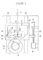
- the winder 11 also includes a traverse device 21, a contact roller 31, and a free length changing means 41 for changing a free length FL between the traverse device 21 and the contact roller 31.
- the slide box 42 provided so as to be able to elevate and lower with respect to the body frame 12, comprises a part of the free length changing means 41.
- the traverse device 21 and the contact roller 31 are provided in the slide box 42.
- the traverse device 21 is located on an upstream side of the contact roller 31 in a traveling direction of the synthetic fiber yarn Y.
- the position of the traverse device 21 is fixed with respect to the slide box 42.
- a traverse guide 22 engaged with the synthetic fiber yarn Y fed from an upper part of Figure 1 reciprocates within a traverse range to traversely move the synthetic fiber yarn Y fed to the downstream direction.
- a traverse motor 23 is provided in the traverse device 21 to drive the traverse guide 22.
- the traverse motor 23 is electrically connected to the controller 13 so that driving of the traverse motor 23 is controlled.
- the controller 13 can change a traverse speed by controlling a rotation speed of the traverse motor 23.
- the traverse device 21 has only to be able to change the traverse speed, and may be a rotary traverse device using rotating blades or any other well-known traverse device.
- the contact roller 31 rotates in conjunction with a package 18 during a package forming period P1 during which the synthetic fiber yarn Y is formed into the package 18.
- the contact roller 31 thus receives the synthetic fiber yarn Y traversed by the traverse device 21 to deliver the synthetic fiber yarn Y to an outer periphery of the package 18.
- the contact roller 31 is rotatably supported on a first end 33 side of an arm 32.
- the arm 32 is provided so as to be swingable with respect to the slide box 42.
- An air cylinder 35 is coupled to a second end 34 side of the arm 32 so as to be located between the slide box 42 and the arm 32.
- the arm 32 swings in a vertical direction to move the contact roller 31 in a direction in which the contact roller 31 approaches the bobbin 17 at the winding position or in a direction in which the contact roller 31 is separated from the bobbin 17. This enables the position of the contact roller 31 relative to the slide box 42 to be changed.
- the air cylinder 35 is a contact pressure adjusting means for allowing the contact roller 31 to contact with an outer peripheral surface of the package 18 under a predetermined contact pressure. The contact roller 31 then rotates in conjunction with the rotating package 18.
- the free length changing means 41 can change the free length FL of the synthetic fiber yarn Y between the contact roller 31 and the traverse device 21 during the package forming period P1.
- the free length changing means 41 is composed of the slide box 42, a rail 43, a ball screw mechanism 44, and the like.
- the free length FL in Embodiment I refers to the free length of the synthetic fiber yarn Y over which the synthetic fiber yarn Y engaged with the traverse device 21 travel after being released from the traverse device 21 and before coming into contact with a peripheral surface of the contact roller 31.
- the slide box 42 is guided along the rail 43, provided on the body frame 12 in the vertical direction.
- the slide box 42 is movable in the vertical direction by means of the ball screw mechanism 44, provided on the body frame 12.
- the ball screw mechanism 44 is composed of a screw rod 45, a ball nut 46, an elevating and lowering driving motor 47, and the like.
- the screw rod 45 is located so as to extend in the vertical direction and is supported so as to be rotatable with respect to the body frame 12.
- the elevating and lowering driving motor 47 rotationally drives the screw rod 45 and is connected to a lower end of the screw rod 45.
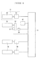
- the elevating and lowering driving motor 47 is electrically connected to the controller 13 so that driving of the elevating and lowering driving motor 47 is controlled (see Figure 4 ).
- the ball nut 46, threadably fitted around the screw rod 45, is provided on the slide box 42.
- the elevating and lowering driving motor 47 rotates the screw rod 45 forward and backward to elevate and lower the slide box 42.
- the slide box 42 elevates to leave the package 18 and lowers to approach the package 18.
- the slide box 42 includes an arm position sensor 36 that detects the tilt arm 32.
- the arm position sensor 36 is electrically connected to the controller 13.
- the arm position sensor 36 is turned on when the arm 32 is placed in a steady-state position with respect to the slide box 42, and is turned off when the arm 32 moves away from the steady-state position by at least a predetermined distance.
- the arm 32 is tilted when winding progress to thicken the package to displace the contact roller 31 upward or when the slide box 42 elevates or lowers to displace the contact roller 31 in the vertical direction. That is, when turned on, the arm position sensor 36 detects that the contact roller 31 is in the steady-state position with respect to the slide box 42. Furthermore, when turned off, the arm position sensor 36 detects that the contact roller 31 is displaced upward or downward relative to the slide box 42.
- the arm 32 includes a rotation sensor 37 that detects the rotation speed of the contact roller 31.
- the rotation sensor 37 detects the rotation speed of the contact roller 31 rotating in conjunction with the package 18 to detect an outer peripheral speed of the package 18.
- the rotation sensor 37 is electrically connected to the controller 13.
- the controller 13 controls driving of the bobbin holder driving motor 19 so that the rotation sensor 37 detects a constant rotation speed. Specifically, when a value detected by the rotation sensor 37 is smaller than a predetermined value corresponding to the winding speed, the controller 13 increases the rotation speed of the bobbin holder driving motor 19. In contrast, when the detected value is larger than the predetermined value, the controller 13 reduces the rotation speed of the bobbin holder driving motor 19.
- control will be described by which free length change is repeated during the package forming period P1 so as to temporarily increase the free length FL and then reduce the free length FL.
- the control is also performed by the conventional saddle bag shape collapsing mechanism, and as shown in Figure 5 , involves repeating two types of control: control for changing the free length and control for maintaining a steady-state free length. That is, the control for changing the free length is intermittently and periodically performed, with the control for maintaining the steady-state free length performed between the intermittent and periodic control operations.
- a program that performs the control is stored in the ROM of the controller 13 and loaded into the RAM for execution.
- a period during which the free length change is performed is defined as a free length changing period F2.
- a period during which the free length has a steady-state value is defined as a free length steady-state period F1.
- control for maintaining the steady-state free length maintains the position of the contact roller 31 relative to the slide box 42 in the steady state.
- control for elevating the slide box 42 is performed as the winding progresses to gradually thicken the package 18 during the package forming period P1.
- the control for elevating the slide box 42 as the winding progresses to gradually thicken the package 18 is performed as follows. As shown in Figure 2 , it is assumed that a certain amount of package 18 has been formed on the bobbin 17, and the radius of the package 18 in this case is defined as (r). The position of the arm 32 in this case is defined as the steady-state position with respect to the slide box 42. It is further assumed that the winding further progresses to thicken the package 18, thus increasing the radius of the package 18 by a very small amount (dr) to (r + r). Then, the contact roller 31 contacting with the package 18 elevates by a height corresponding to the increase in winding radius (dr), relative to the slide box 42. Compared to the state shown in Figure 2 , the position of the arm 32 is tilted upward from the steady-state position relative to the slide box 42.
- the arm position sensor 36 in the on state is turned off to detect that the arm 32 is tilted and then transmits a signal to the controller 13.
- the controller 13 drives the elevating and lowering driving motor 47 in the ball screw mechanism 44 to elevate the slide box 42 by the increase in winding radius (dr).
- the control is performed such that the slide box 42 is elevated to lower the contact roller 31 with respect to the slide box 42 to return the position of the contact roller 31 with respect to the slide box 42, to the original steady-state position.
- the arm position sensor 36 detects the position of the contact roller 31 relative to the slide box 42.
- the control is performed such that the slide box 42 is elevated to return the position of the contact roller 31 relative to the slide box 42, to the original position.
- the control gradually elevates the slide box 42 as the winding progresses to gradually thicken the package 18 during the package forming period P1. This also keeps constant the free length of the synthetic fiber yarn Y between the traverse guide 22 of the traverse device 21 and the peripheral surface of the contact roller 31.
- the control for maintaining the minimum free length FL keeps the minimum difference (traverse delay) between an axial position to which the synthetic fiber yarn Y is traversed and an axial position at which the synthetic fiber yarn Y is actually received by the contact roller 31.
- the package 18 can be formed so as to have a set winding width.
- the control temporarily increases and then reduces the free length FL during the package forming period P1 regardless of the thickening of the package 18 resulting from the progress of the winding.
- the free length FL is increased and then reduced to the original value.
- the controller 13 drives the elevating and lowering driving motor 47 to temporarily elevate the slide box 42. Elevating the slide box 42 causes the contact roller 31 to lower relative to the slide box 42 owing to the weight thereof while remaining in contact with the package 18.
- the traverse device 21, which is fixed to the slide box 42 elevates together with the slide box 42.
- the controller 13 drives the elevating and lowering driving motor 47 in the opposite direction to lower the slide box 42.
- the free length FL is thus reduced.
- the controller 13 thus completes the control for changing the free length FL.
- the free length steady-state period F1 and the free length changing period F2 are repeated during the package forming period P1.
- the winding during the free length steady-state period F1 slightly increases the saddle bag shape of the package 18
- the winding during the free length changing period F2 reduces the winding width to allow the synthetic fiber yarn Y to be wound the package 18 at a position closer to the axial center thereof (the amount of change in winding width W1).
- Control performed by the conventional saddle bag shape collapsing mechanism, described above, may sufficiently dissolve the saddle bag shape phenomenon.
- the control may less effectively adjust the winding width and fail to sufficiently dissolve the saddle bag shape phenomenon.
- a large value of the reference winding angle A1 allows the winding width to be very effectively adjusted to sufficiently dissolved the saddle bag shape phenomenon, whereas a small value of the reference winding angle A1 reduces the effect of adjusting the winding width to prevent the saddle bag shape phenomenon from being sufficiently dissolved.
- the large value of the reference winding angle is, for example, at least 10 degrees.
- the small value of the reference winding angle is, for example, at most 6 degrees.
- the synthetic fiber yarn Y is wound around the package 18 at the position closer to the axial center thereof by the distance corresponding to the difference in traverse delay (D2 - D1). This allows the winding width to be very effectively adjusted.
- the synthetic fiber yarn Y is wound around the package 18 so as to be traversed to an axially outward position thereof. This reduces the effect of adjusting the winding width. Therefore, the reduced value of the reference angle A1, that is, a reduced value of the traverse delay, reduces the effect of reducing the winding width of the synthetic fiber yarn Y even with the temporary increase in free length FL. The saddle bag shape phenomenon is thus prevented from being sufficiently dissolved.
- the winder 11 temporarily increases the winding angle at a timing at which the free length FL is temporarily increased from FL1 to FL2. That is, as shown in Figure 8 , the winder 11 performs control such that the traverse device 21 changes the traverse speed so as to increase the winding angle at the same time when the free length FL is temporarily increased from FL1 to FL2.
- the control involves repeating two types of control: control for changing the traverse speed and the control for maintaining a steady-state traverse speed. That is, the control for changing the traverse speed is intermittently and periodically performed, with the control for maintaining the steady-state traverse speed performed between the intermittent and periodic control operations.
- a program that performs the control is stored in the ROM of the controller 13 and loaded into the RAM for execution.
- a period during which the traverse speed change is performed is defined as a traverse speed changing period T2.
- a period during which the traverse speed has a steady-state value is defined as a traverse speed steady-state period T1.
- the traverse speed changing period T2 is matched with the free length changing period F2, described above.
- the control maintains the steady-state traverse speed and thus a steady-state winding angle.
- the winding angle in this case is the reference winding angle A1, determined by the high-order requirements such as the type of the synthetic fiber yarn Y.
- the traverse speed (reference speed V1) corresponding to the reference winding angle A1 is calculated.
- the traverse speed (reference speed V1) corresponding to the reference winding angle A1 is preset in a program for the controller 13.
- the reference speed V1 is constant, and the controller 13 controls driving of the traverse motor 23 so as to keep the traverse speed equal to the reference speed V1.
- the control repeats, during the package forming period P1, an operation of temporarily increasing the traverse speed from a reference speed V1 to a target speed V2 and then reducing the traverse speed to the reference speed V1.
- the target speed V2 is a traverse speed corresponding to a winding angle (target winding angle A2) at which a change in free length FL during the free length changing period F2 allows the winding width of the synthetic fiber yarn Y to be effectively reduced.
- the target winding angle A2 and the target speed V2 are determined based on the amount of change in free length FL (FL2 - FL1) and the reference winding angle A1.
- the target winding angle A2 and the target speed V2 are preset in a program for the controller 13.
- the controller 13 controls driving of the traverse motor 23 so as to temporarily increase the traverse speed from the reference speed V1 to the target speed V2 and then reduce the traverse speed to the reference speed V1.
- the reference speed V1 is constant, the reference speed V1 before a change in traverse speed is the same as that after the change.
- the traverse speed changing period T2, during which the traverse speed change is performed is matched with the free length changing period F2, during which the free length change is performed.
- the winding angle can be temporarily increased during the free length change. Consequently, even if the reference winding angle A1 is reduced in response to the high-order requirements such as the type of the synthetic fiber yarn Y, the winding angle can be temporarily increased during the free length change. Therefore, the winding width can be sufficiently effectively adjusted to allow the saddle bag shape phenomenon to be effectively dissolved.
- the winder 11 as a yarn winding machine according to Embodiment 2 of the present invention will be described with reference to Figures 9 and 10 .
- Embodiment 2 differs significantly from Embodiment 1 in that the winder 11 according to Embodiment 2 corresponds to the winder 11 according to Embodiment I in which a bulge suppressing mechanism is additionally provided. A detailed description of the same components as those of Embodiment 1 is omitted.
- the bulge suppressing mechanism is conventionally known. To dissolve the possible bulge winding of the package 18, the bulge suppressing mechanism gradually changes the winding angle between a former stage P2 and a latter stage P3 of the package forming period P1 as shown in Figure 9 .
- the winding angle in this case is the reference winding angle A1, determined by the high-order requirements such as the type of the synthetic fiber yarn Y.
- the bulge suppressing mechanism changes the reference winding angle A1.
- the bulge suppressing mechanism in the former stage P2 of the package forming period P1, the winding is started with a small value of the reference winding angle A1, and the reference winding angle A1 is then gradually increased.
- the reference winding angle A1 is gradually reduced to the small value, until the winding is completed.
- the bulge suppressing mechanism gradually changes the density of the package 18 from high to low in the former stage P2 and from low to high in the latter stage P3. A yarn layer is thus prevented from being excessively tightened to dissolve the possible bulge winding.
- the bulge inhibiting mechanism may disadvantageously degrade the effect of adjusting the winding width.
- the bulge inhibiting mechanism may disadvantageously degrade the effect of adjusting the winding width.
- the bulge suppressing mechanism reduces the reference winding angle A1 near a winding start position and a winding end position of package 18 as shown in Figure 9 . Reducing the reference winding angle A1 near the winding start and end positions of the package 18 prevents the saddle bag shape collapsing mechanism from effectively adjusting the winding width during the corresponding period. This dissolve the avoidance of the saddle bag shape phenomenon.
- the winder 11 according to Embodiment 2 temporarily increases the winding angle at the same time when the free length FL is temporarily increased as shown in Figure 10 . Then, the winder 11 increases the amount of change in the winding angle near the winding start and end positions of the package 18, where the reference winding angle A1 is small.
- the control of the traverse speed according to Embodiment 2 will be described in detail.
- the control involves repeating two types of control:
- the reference winding angle A1 (reference speed V1) decreases gradually.
- the traverse speed is changed slowly.
- a program that performs the control is stored in the ROM of the controller 13 and loaded into the RAM for execution.
- the traverse speed changing period T2 is matched with the free length changing period F2, described above.
- the control for maintaining the steady-state traverse speed will be described.
- the control maintains the steady-state traverse speed and thus a steady-state winding angle.
- the winding angle in this case is the reference winding angle A1, determined by the high-order requirements such as the type of the synthetic fiber yarn Y and by the bulge suppressing mechanism.
- the reference winding angle A1 changes gradually during the package forming period P1.
- the traverse speed (reference speed V1) corresponding to the reference winding angle A1 is calculated and preset in the program for the controller 13.
- the controller 13 controls driving of the traverse motor 23 so as to keep the traverse speed equal to the reference speed V1.
- the control repeats, during the package forming period P1, the operation of temporarily increasing the traverse speed from the reference speed V1 to the target speed V2 and then reducing the traverse speed to the reference speed VI.
- the target speed V2 is the traverse speed corresponding to the winding angle (target winding angle A2) at which a change in free length FL during the free length changing period F2 allows the winding width of the synthetic fiber yarn Y to be effectively reduced.
- the target winding angle A2 and the target speed V2 are determined based on the amount of change in free length FL (FL2 - FL1) and the reference winding angle A1.
- the target winding angle A2 and the target speed V2 are preset in the program for the controller 13.
- the controlled 13 controls driving of the traverse motor 23 so as to temporarily increase the traverse speed from the reference speed V1 to the target speed V2 and then reduce the traverse speed to the reference speed VI.
- the reference speed V1 since the reference speed V1 changes, the reference speed V1 before the change in traverse speed is different from that after the change.
- the reference speed V1 is gradually increased in the former stage P2 of the package forming period P1. Furthermore, in the latter stage P3, the reference speed V1 is gradually reduced. Consequently, the yarn layer is prevented from being excessively tightened, thus dissolving the bulge winding. Additionally, even when the synthetic fiber yarn Y is located near the winding start or end position of the package 18, that is, in the stage in which the reference winding angle A1 is small, the traverse speed is temporarily increased from the reference speed V1 to the target speed V2. Thus, the winding angle can be temporarily increased to allow the winding width to be sufficiently effectively adjusted. Accordingly, the possible high selvage phenomenon can be effectively dissolved. As a result, both the possible high selvage phenomenon and bulge winding can be dissolved.
- the present invention is not limited to the above-described embodiments.
- the embodiments may be changed, for example, as follows.
- the traverse speed changing period T2 during which the traverse speed change is performed is matched with the free length changing period F2, during which the free length change is performed.
- the present invention is not limited to the matching of the periods T2 and F2 with each other.
- the traverse speed changing period T2 and the free length changing period F2 have only to overlap each other. That is, the timing for the traverse speed change need not perfectly match the timing for the free length change.
- the increase in free length FL allows the winding width to be significantly effectively adjusted. This enables the saddle bag shape phenomenon to be more effectively dissolved.
- the target speed V2 for the traverse speed is constant.
- the target speed V2 may be adjustable.
- the target speed V2 can be set to a value at which the winding width can be very effectively adjusted.
- the saddle bag shape phenomenon can be effectively dissolved.
- a start time, the number of times, the amount of change, and an end time can each be appropriately adjusted.
Applications Claiming Priority (1)
| Application Number | Priority Date | Filing Date | Title |
|---|---|---|---|
| JP2008084617A JP4776650B2 (ja) | 2008-03-27 | 2008-03-27 | 糸条巻取り機及び糸条巻取り方法 |
Publications (3)
| Publication Number | Publication Date |
|---|---|
| EP2105400A2 true EP2105400A2 (fr) | 2009-09-30 |
| EP2105400A3 EP2105400A3 (fr) | 2009-12-23 |
| EP2105400B1 EP2105400B1 (fr) | 2012-08-01 |
Family
ID=40718738
Family Applications (1)
| Application Number | Title | Priority Date | Filing Date |
|---|---|---|---|
| EP09150423A Active EP2105400B1 (fr) | 2008-03-27 | 2009-01-13 | Machine de bobbinage de fil et procédé de bobbinage de fil |
Country Status (4)
| Country | Link |
|---|---|
| EP (1) | EP2105400B1 (fr) |
| JP (1) | JP4776650B2 (fr) |
| KR (1) | KR101249308B1 (fr) |
| CN (1) | CN101544321B (fr) |
Families Citing this family (5)
| Publication number | Priority date | Publication date | Assignee | Title |
|---|---|---|---|---|
| JP2012144323A (ja) * | 2011-01-11 | 2012-08-02 | Tmt Machinery Inc | 紡糸巻取装置及び紡糸巻取設備 |
| JP2020147382A (ja) * | 2019-03-11 | 2020-09-17 | 村田機械株式会社 | 糸巻取機、及び、糸巻取方法 |
| CN110902488B (zh) * | 2019-11-12 | 2021-07-20 | 安徽怡和电缆有限公司 | 一种辅助塑料绝缘控制电缆盘绕的导向架 |
| JP2022045513A (ja) | 2020-09-09 | 2022-03-22 | Tmtマシナリー株式会社 | 糸巻取機 |
| DE102022001140A1 (de) * | 2022-04-01 | 2023-10-05 | Oerlikon Textile Gmbh & Co. Kg | Verfahren zum Aufwickeln eines Spinnfadens und Aufwickelvorrichtung zum Aufwickeln eines Spinnfadens |
Citations (1)
| Publication number | Priority date | Publication date | Assignee | Title |
|---|---|---|---|---|
| JP2005225611A (ja) | 2004-02-13 | 2005-08-25 | Tmt Machinery Inc | 弾性糸の巻取方法及び弾性糸用巻取機 |
Family Cites Families (4)
| Publication number | Priority date | Publication date | Assignee | Title |
|---|---|---|---|---|
| JP2706343B2 (ja) * | 1990-01-18 | 1998-01-28 | 東レ株式会社 | ドラム状パッケージへの糸条巻上げ方法 |
| DE10021963A1 (de) * | 1999-05-14 | 2000-12-21 | Barmag Barmer Maschf | Verfahren und Vorrichtung zum Aufwickeln eines kontinuierlich zulaufenden Fadens |
| JP2005126186A (ja) * | 2003-10-23 | 2005-05-19 | Toray Ind Inc | 糸条巻取方法と糸条パッケージ |
| JP4326979B2 (ja) * | 2004-02-13 | 2009-09-09 | Tmtマシナリー株式会社 | 弾性糸用巻取システム、弾性糸用巻取機及び弾性糸の巻取方法 |
-
2008
- 2008-03-27 JP JP2008084617A patent/JP4776650B2/ja active Active
- 2008-12-23 KR KR1020080132255A patent/KR101249308B1/ko active IP Right Grant
-
2009
- 2009-01-13 EP EP09150423A patent/EP2105400B1/fr active Active
- 2009-03-10 CN CN2009101269495A patent/CN101544321B/zh active Active
Patent Citations (1)
| Publication number | Priority date | Publication date | Assignee | Title |
|---|---|---|---|---|
| JP2005225611A (ja) | 2004-02-13 | 2005-08-25 | Tmt Machinery Inc | 弾性糸の巻取方法及び弾性糸用巻取機 |
Also Published As
| Publication number | Publication date |
|---|---|
| KR20090103685A (ko) | 2009-10-01 |
| EP2105400B1 (fr) | 2012-08-01 |
| JP4776650B2 (ja) | 2011-09-21 |
| CN101544321B (zh) | 2012-10-24 |
| EP2105400A3 (fr) | 2009-12-23 |
| CN101544321A (zh) | 2009-09-30 |
| KR101249308B1 (ko) | 2013-04-01 |
| JP2009234755A (ja) | 2009-10-15 |
Similar Documents
| Publication | Publication Date | Title |
|---|---|---|
| EP2145849B1 (fr) | Bobinoir | |
| EP2664570B1 (fr) | Dispositif de bobinage de filé et installation de bobinage de filé | |
| US5029762A (en) | Yarn winding apparatus and method | |
| CN100522779C (zh) | 弹性纱线卷绕系统、弹性纱线卷绕机和弹性纱线卷绕方法 | |
| JP5884280B2 (ja) | 糸巻取装置及び糸巻取方法 | |
| EP2105400B1 (fr) | Machine de bobbinage de fil et procédé de bobbinage de fil | |
| EP2221265B1 (fr) | Machine de renvideur de fil et procédé de renvidage de fil | |
| CN101544323B (zh) | 纱线卷绕机及纱线卷绕方法 | |
| JP2013040047A (ja) | 巻取機の制御方法およびその制御方法 | |
| EP3363756B1 (fr) | Enrouleur de fils | |
| EP3950552B1 (fr) | Enrouleur de fils | |
| JP2000026021A (ja) | 綾巻きボビンを作製する繊維機械の作動方法 | |
| JP2004277949A (ja) | 紡績機 | |
| WO2020031457A1 (fr) | Bobinoir de fil | |
| JP2005225611A (ja) | 弾性糸の巻取方法及び弾性糸用巻取機 | |
| JP2008522926A (ja) | 巻取機 | |
| JP3690351B2 (ja) | 糸条巻取機及び糸条巻取方法 | |
| JP5766576B2 (ja) | 紡糸巻取装置 | |
| EP0963936A1 (fr) | Procédé de bobinage de fil pour un bobinoir et bobinoir | |
| JP2003020167A (ja) | 巻取機のスピンドル位置制御方法 | |
| TW202128546A (zh) | 繞線裝置及繞線方法 | |
| JP2652702B2 (ja) | パーンの成形方法とその装置 | |
| JPH07196254A (ja) | レボルビング型巻糸機 | |
| JPS617162A (ja) | コイル材給送装置 | |
| JPH04140273A (ja) | パーン巻取機における糸条巻取方法 |
Legal Events
| Date | Code | Title | Description |
|---|---|---|---|
| PUAI | Public reference made under article 153(3) epc to a published international application that has entered the european phase |
Free format text: ORIGINAL CODE: 0009012 |
|
| AK | Designated contracting states |
Kind code of ref document: A2 Designated state(s): AT BE BG CH CY CZ DE DK EE ES FI FR GB GR HR HU IE IS IT LI LT LU LV MC MK MT NL NO PL PT RO SE SI SK TR |
|
| AX | Request for extension of the european patent |
Extension state: AL BA RS |
|
| PUAL | Search report despatched |
Free format text: ORIGINAL CODE: 0009013 |
|
| AK | Designated contracting states |
Kind code of ref document: A3 Designated state(s): AT BE BG CH CY CZ DE DK EE ES FI FR GB GR HR HU IE IS IT LI LT LU LV MC MK MT NL NO PL PT RO SE SI SK TR |
|
| AX | Request for extension of the european patent |
Extension state: AL BA RS |
|
| 17P | Request for examination filed |
Effective date: 20100331 |
|
| AKX | Designation fees paid |
Designated state(s): DE IT |
|
| 17Q | First examination report despatched |
Effective date: 20110118 |
|
| GRAP | Despatch of communication of intention to grant a patent |
Free format text: ORIGINAL CODE: EPIDOSNIGR1 |
|
| GRAS | Grant fee paid |
Free format text: ORIGINAL CODE: EPIDOSNIGR3 |
|
| GRAA | (expected) grant |
Free format text: ORIGINAL CODE: 0009210 |
|
| AK | Designated contracting states |
Kind code of ref document: B1 Designated state(s): DE IT |
|
| REG | Reference to a national code |
Ref country code: DE Ref legal event code: R096 Ref document number: 602009008581 Country of ref document: DE Effective date: 20120927 |
|
| PLBE | No opposition filed within time limit |
Free format text: ORIGINAL CODE: 0009261 |
|
| STAA | Information on the status of an ep patent application or granted ep patent |
Free format text: STATUS: NO OPPOSITION FILED WITHIN TIME LIMIT |
|
| 26N | No opposition filed |
Effective date: 20130503 |
|
| REG | Reference to a national code |
Ref country code: DE Ref legal event code: R097 Ref document number: 602009008581 Country of ref document: DE Effective date: 20130503 |
|
| PGFP | Annual fee paid to national office [announced via postgrant information from national office to epo] |
Ref country code: IT Payment date: 20230126 Year of fee payment: 15 |
|
| P01 | Opt-out of the competence of the unified patent court (upc) registered |
Effective date: 20230426 |
|
| PGFP | Annual fee paid to national office [announced via postgrant information from national office to epo] |
Ref country code: DE Payment date: 20240112 Year of fee payment: 16 |