EP2105247B1 - Système de positionnement - Google Patents
Système de positionnement Download PDFInfo
- Publication number
- EP2105247B1 EP2105247B1 EP08153254.1A EP08153254A EP2105247B1 EP 2105247 B1 EP2105247 B1 EP 2105247B1 EP 08153254 A EP08153254 A EP 08153254A EP 2105247 B1 EP2105247 B1 EP 2105247B1
- Authority
- EP
- European Patent Office
- Prior art keywords
- positioning unit
- motor member
- moving motor
- arrangement
- positioning
- Prior art date
- Legal status (The legal status is an assumption and is not a legal conclusion. Google has not performed a legal analysis and makes no representation as to the accuracy of the status listed.)
- Active
Links
- 238000001816 cooling Methods 0.000 claims description 36
- 230000033001 locomotion Effects 0.000 claims description 30
- 230000005540 biological transmission Effects 0.000 claims description 25
- 239000000758 substrate Substances 0.000 claims description 20
- 238000004519 manufacturing process Methods 0.000 description 8
- 230000008901 benefit Effects 0.000 description 3
- 230000001627 detrimental effect Effects 0.000 description 3
- 230000000694 effects Effects 0.000 description 3
- 239000000853 adhesive Substances 0.000 description 2
- 230000001070 adhesive effect Effects 0.000 description 2
- 239000004020 conductor Substances 0.000 description 2
- 238000013021 overheating Methods 0.000 description 2
- 229910000679 solder Inorganic materials 0.000 description 2
- 238000012546 transfer Methods 0.000 description 2
- 230000009466 transformation Effects 0.000 description 2
- RYGMFSIKBFXOCR-UHFFFAOYSA-N Copper Chemical compound [Cu] RYGMFSIKBFXOCR-UHFFFAOYSA-N 0.000 description 1
- XEEYBQQBJWHFJM-UHFFFAOYSA-N Iron Chemical group [Fe] XEEYBQQBJWHFJM-UHFFFAOYSA-N 0.000 description 1
- 230000004075 alteration Effects 0.000 description 1
- XAGFODPZIPBFFR-UHFFFAOYSA-N aluminium Chemical compound [Al] XAGFODPZIPBFFR-UHFFFAOYSA-N 0.000 description 1
- 229910052782 aluminium Inorganic materials 0.000 description 1
- 238000005452 bending Methods 0.000 description 1
- 230000008859 change Effects 0.000 description 1
- 238000010276 construction Methods 0.000 description 1
- 229910052802 copper Inorganic materials 0.000 description 1
- 239000010949 copper Substances 0.000 description 1
- 230000001419 dependent effect Effects 0.000 description 1
- 238000013461 design Methods 0.000 description 1
- 230000004907 flux Effects 0.000 description 1
- 239000003292 glue Substances 0.000 description 1
- 239000011229 interlayer Substances 0.000 description 1
- 239000010410 layer Substances 0.000 description 1
- 239000000463 material Substances 0.000 description 1
- 238000000034 method Methods 0.000 description 1
- 238000012986 modification Methods 0.000 description 1
- 230000004048 modification Effects 0.000 description 1
- 230000001095 motoneuron effect Effects 0.000 description 1
- 230000008520 organization Effects 0.000 description 1
- 238000012545 processing Methods 0.000 description 1
- 230000009467 reduction Effects 0.000 description 1
- 238000007650 screen-printing Methods 0.000 description 1
- 239000000725 suspension Substances 0.000 description 1
Images


Classifications
-
- H—ELECTRICITY
- H05—ELECTRIC TECHNIQUES NOT OTHERWISE PROVIDED FOR
- H05K—PRINTED CIRCUITS; CASINGS OR CONSTRUCTIONAL DETAILS OF ELECTRIC APPARATUS; MANUFACTURE OF ASSEMBLAGES OF ELECTRICAL COMPONENTS
- H05K13/00—Apparatus or processes specially adapted for manufacturing or adjusting assemblages of electric components
- H05K13/04—Mounting of components, e.g. of leadless components
-
- B—PERFORMING OPERATIONS; TRANSPORTING
- B23—MACHINE TOOLS; METAL-WORKING NOT OTHERWISE PROVIDED FOR
- B23Q—DETAILS, COMPONENTS, OR ACCESSORIES FOR MACHINE TOOLS, e.g. ARRANGEMENTS FOR COPYING OR CONTROLLING; MACHINE TOOLS IN GENERAL CHARACTERISED BY THE CONSTRUCTION OF PARTICULAR DETAILS OR COMPONENTS; COMBINATIONS OR ASSOCIATIONS OF METAL-WORKING MACHINES, NOT DIRECTED TO A PARTICULAR RESULT
- B23Q5/00—Driving or feeding mechanisms; Control arrangements therefor
- B23Q5/22—Feeding members carrying tools or work
- B23Q5/28—Electric drives
-
- H—ELECTRICITY
- H02—GENERATION; CONVERSION OR DISTRIBUTION OF ELECTRIC POWER
- H02K—DYNAMO-ELECTRIC MACHINES
- H02K41/00—Propulsion systems in which a rigid body is moved along a path due to dynamo-electric interaction between the body and a magnetic field travelling along the path
- H02K41/02—Linear motors; Sectional motors
-
- H—ELECTRICITY
- H05—ELECTRIC TECHNIQUES NOT OTHERWISE PROVIDED FOR
- H05K—PRINTED CIRCUITS; CASINGS OR CONSTRUCTIONAL DETAILS OF ELECTRIC APPARATUS; MANUFACTURE OF ASSEMBLAGES OF ELECTRICAL COMPONENTS
- H05K13/00—Apparatus or processes specially adapted for manufacturing or adjusting assemblages of electric components
- H05K13/04—Mounting of components, e.g. of leadless components
- H05K13/0404—Pick-and-place heads or apparatus, e.g. with jaws
- H05K13/0406—Drive mechanisms for pick-and-place heads, e.g. details relating to power transmission, motors or vibration damping
-
- H—ELECTRICITY
- H05—ELECTRIC TECHNIQUES NOT OTHERWISE PROVIDED FOR
- H05K—PRINTED CIRCUITS; CASINGS OR CONSTRUCTIONAL DETAILS OF ELECTRIC APPARATUS; MANUFACTURE OF ASSEMBLAGES OF ELECTRICAL COMPONENTS
- H05K13/00—Apparatus or processes specially adapted for manufacturing or adjusting assemblages of electric components
- H05K13/04—Mounting of components, e.g. of leadless components
- H05K13/046—Surface mounting
- H05K13/0469—Surface mounting by applying a glue or viscous material
-
- Y—GENERAL TAGGING OF NEW TECHNOLOGICAL DEVELOPMENTS; GENERAL TAGGING OF CROSS-SECTIONAL TECHNOLOGIES SPANNING OVER SEVERAL SECTIONS OF THE IPC; TECHNICAL SUBJECTS COVERED BY FORMER USPC CROSS-REFERENCE ART COLLECTIONS [XRACs] AND DIGESTS
- Y10—TECHNICAL SUBJECTS COVERED BY FORMER USPC
- Y10T—TECHNICAL SUBJECTS COVERED BY FORMER US CLASSIFICATION
- Y10T29/00—Metal working
- Y10T29/53—Means to assemble or disassemble
- Y10T29/5313—Means to assemble electrical device
- Y10T29/53174—Means to fasten electrical component to wiring board, base, or substrate
Definitions
- the present invention relates to the field of circuit board manufacturing. More specifically, the invention relates to a positioning system for positioning a positioning unit along an elongated beam extending along an axis (see for example US-A-4922143 ). The invention also relates to a component mounting machine and a dispensing machine comprising the positioning system mentioned above.
- a substrate such as a printed circuit board (PCB)
- a pick-and-place or component mounting machine The electronic components are picked from component feeder magazines and positioned on the substrate, for mechanical and/or electrical connection to the substrate, by a work head, often referred to as a pick-up head or component mounting head.
- the substrate Prior to placing components on a substrate, the substrate has typically been provided with a viscous medium in the form of solder paste or glue at accurately determined locations on the substrate at which the component is to be placed and attached to the substrate.
- the application of the viscous medium is typically provided through screen printing, dispensing or jetting.
- Such dispensing or jetting is typically provided through a work head, also referred to as a dispensing or jetting head.
- Servo controlled linear motions of the work head may be provided in the x and y directions, or along the x- and y-axes, i.e. in the general, horizontal plane of the circuit board, and in the z direction, or along the z-axis, i.e. vertically and generally perpendicular to the plane of the circuit board.
- a work head used for jetting there may be no need for providing motion of the work head in the z direction, which however is vital for a dispensing and a component mounting head.
- the driving movable motor member is provided with a number of iron cores having thereon wounded copper cable, i.e. an electric conductor.
- the oppositely arranged stationary motor member is provided with a number of magnetic elements arranged in a row along an axis. Preferably, these magnetic elements are angularly adjusted or tilted, thereby providing a more precise and continuous linear motion.
- electric current flows back and forth through the electric circuit coils surrounding the cores, thereby generating heat which may result in thermal expansion of the moving motor member.
- a linear motor arrangement used in a positioning system that is intended for precise and fast linear motion generates a large amount of heat.
- the heat causes the moving motor member to expand, possibly bend, which may result in a strained connection with built-in stress to a thereto connected positioning unit, which in turn may cause deformation of said positioning unit.
- Deformations of the positioning unit may also arise from thermal deviations of the positioning unit per se, if the positioning unit is subjected to large temperature variations.
- Such a deformation may result in changes in the relative positions and orientations of elements comprised in or carried by the positioning unit, such as the nominal centre of the positioning unit, a detector for detecting the position along the positioning axis, a camera for detecting reference markings on a substrate or the like, and one or more work heads, e.g. component mounting heads and/or dispensing heads.
- a change in relative position, i.e. offset, between different elements carried by the positioning unit is undesired, since it is likely to have a detrimental effect on the accuracy in the positioning of the work heads, and thereby result in a decrease in production accuracy or, as a result of correcting for inaccuracies, production speed.
- An object of the present invention is to provide an improved positioning system for positioning a positioning unit along an axis.
- a positioning system for positioning a positioning unit along a longitudinal axis.
- the positioning system comprises a linear guide arrangement for enabling a linearly guided motion parallel to said axis, wherein the positioning unit is operatively connected to said guide arrangement.
- the positioning system comprises a motor, wherein the motor comprises a moving motor member operatively connected to said linear guide arrangement and an elongated stationary motor member extending parallel to said axis.
- the moving motor member is adapted to move along the stationary motor member for providing motion parallel to said axis.
- the positioning system further comprises a force transmission arrangement which operatively connects said moving motor member to the positioning unit.
- the force transmission arrangement is arranged to provide an engagement between said positioning unit and said moving motor.
- the engagement is rigid in a direction parallel to said axis for instantaneous transmission of a linear force, and is resilient in directions other than said direction parallel to said axis, whereby transmission to the positioning unit of forces arising from thermal expansion of the motor is reduced or eliminated.
- a component mounting machine which is arranged for mounting electronic components onto substrates, the machine having a positioning system according to the preceding paragraph.
- a jetting machine for jet dispensing of individual drops of viscous medium onto substrates, the machine having a positioning system according to said preceding paragraph.
- a dispensing machine for dispensing of viscous medium onto substrates, the machine having a positioning system according to said preceding paragraph.
- the present invention is based on the insight of using a force transmission arrangement operatively connecting a positioning unit to a motor for linear motion along a linear motion direction, wherein the force transmission arrangement provides a semi-rigid engagement between the moving motor member and the positioning unit that is rigid in the direction parallel with said axis, i.e. in a linear motion direction, and wherein the engagement is resilient in all other directions.
- the linear driving force of the moving motor member can be directly transmitted to the positioning unit during operation of the positioning system.
- any deformation of the moving motor member as a result of thermal expansion is compensated for by allowing the relative spatial distance or space between the moving motor member and the positioning unit to vary, whereby the orientation of the positioning unit and the shape thereof is unaffected by the thermal deformations of the moving motor member.
- the term “semi-rigid” as used herein is intended to refer to an element that is rigid to some degree or in some parts.
- the term “resilient” as used herein is intended to refer to an element that is capable of resuming its shape after being subjected to shape deforming forces. Consequently, the semi-rigid engagement of the force transmission arrangement is thereby partially rigid, i.e. the engagement is rigid in the linear motion direction. Furthermore, during the operation of the positioning system, the engagement is affected by thermally induced forces which need to be taken care of, and which otherwise would compromise the intended function of the force transmission arrangement.
- the semi-rigid engagement is thereby resilient in directions other than the rigid direction for springily absorbing such forces.
- said forces fade away concurrently with the cooling of the system, which thereby restores the semi-rigid engagement to its initial shape and form.
- positioning unit refers to an element which is to be put in certain position.
- the term positioning unit refers to a unit for positioning a pick-up head or placement head intended for placement of components on substrates, i.e. in a component mounting machine.
- a positioning unit may also be arranged for positioning a jet dispensing head in a jet dispensing machine, a dispensing head in a machine for conventional dispensing, or in some embodiments, a unit adapted to position, in turn, another positioning unit.
- the positioning unit may be accurately positioned and at a high speed along an axis irrespective of the thermally induced deformations of the moving motor member which is intended for driving the positioning unit along a linear guide arrangement, i.e. along an axis.
- the driving member of the motor i.e. the moving motor member
- the intermediate force transmission connection e.g. offsets the positioning unit relative to the guide arrangement.
- the heat induced offsetting forces are reduced, and in some cases even eliminated, ensuring an accurate and fast positioning of a positioning unit.
- the positioning unit is essentially fixed with respect to said axis in directions orthogonal to said axis when moving back and forth along the axis.
- the spatial motion of the positioning unit is limited to a motion along an axis, thereby ensuring an accurate positioning of the positioning unit.
- the system comprises an elongated beam extending along the axis and the linear guide arrangement is attached to said beam such that the linear guide arrangement can provide a linear motion along said axis, i.e. in a linear motion direction.
- the beam preferably made of a rigid material, provides rigidity to the positioning system, thereby enabling even further a linear motion accuracy of the positioning unit.
- the linear guide arrangement comprises at least two elongated guide portions, which are arranged in parallel with the axis.
- the positioning unit operatively connects the guide arrangement by means of at least two points of engagement.
- the forces that operatively connects the positioning unit to the guide arrangement are distributed, thereby enabling a smooth linear motion and a reduction in the stress, said stress being due to inertia arising during the back and forth motion of the positioning unit.
- Such elongated guide portions may, for example, be a pair of guide rails arranged in parallel.
- the guide portions may also be attached to the beam, and may in some embodiments include an upper and a lower elongated linear guide portion parallel to the axis.
- the linear guide arrangement may comprise a single linear guide.
- the positioning unit and moving motor member are operatively connected to the linear guide arrangement by means of at least two guide engaging carriages.
- Such carriages spatially locks the moving motor member and the positioning unit, respectively, to the guide arrangement, for example the at least two elongated guide portions, in a manner such that only a linear motion along the guide arrangement is allowed.
- the moving motor member and positioning unit are suspended by means of at least an upper and a lower guide engaging carriage from said upper and lower guide portions, respectively.
- the positioning unit and the moving motor member share at least one common guide engaging carriage.
- the positioning unit and moving motor member are both connected to a common carriage.
- the positioning unit may be moved partly independently relative to the moving motor member in the sense that the positioning unit is unaffected by a thermally induced expansion of the moving motor member.
- the positioning unit is attached to the guide engaging carriages by means of resilient positioning unit holders, whereby transmission to the positioning unit via said carriages of forces arising from thermal expansion of the motor is reduced or eliminated.
- Said resilient positioning unit holders may have various shapes to provide the resilient feature or characteristic of the holders.
- the positioning unit holders provide an essentially rigid fixation with respect to said axis in directions orthogonal to said axis when moving back and forth along the axis.
- the positioning unit holders are resilient in a direction parallel to the axis, i.e. the moving direction.
- the positioning unit holders resiliently reduces and absorbs stress related forces arising from, for example, thermally induced expansion of the moving motor member. Stress related forces in the positioning unit are thereby reduced or eliminated, ensuring the dimensional integrity of the positioning unit.
- the positioning unit and the moving motor member share at least two upper and two lower guide engaging carriages.
- the moving motor member is fixedly attached to said two upper carriages and attached to the lower carriages by means of resilient moving motor holders, or vice versa
- the positioning unit is attached to guide engaging carriages by means of resilient positioning unit holders.
- the resilient moving motor holders provide a resilient feature in directions orthogonal to said axis.
- the resilient positioning unit holders attached to the upper carriages are preferably resilient in the moving direction parallel to the axis.
- the resilient positioning unit holders attached to the lower carriages are essentially resilient in all directions.
- the positioning unit and the moving motor member have separate guide engaging carriages. Furthermore, the moving motor member is fixedly attached to at least one upper carriage and attached to at least one lower carriage by means of a resilient moving motor holder, and the positioning unit is fixedly attached to further upper and lower carriages.
- The, need for resilient holders for attaching the positioning unit to the carriages may be eliminated due to the provision of separate carriages.
- the force transmission arrangement still resiliently absorbs any undesirable thermally induced forces from the moving motor member.
- the moving motor member is arranged between the stationary motor member and the positioning unit.
- the moving motor member is centered relative to the positioning unit in the direction parallel with the axis.
- the positioning unit and the moving motor member share a common longitudinal space portion of the linear guide arrangement.
- the elongated space of beam is thus used in an space efficient manner, thereby ensuring that the entire length of the beam may be used for positioning the positioning unit.
- the system further comprises a cooling arrangement for conduction of heat away from the moving motor member for limiting heat-induced deformations or expansions of the motor, as well as preventing possible overheating.
- the cooling arrangement is mounted to the moving motor member such that the moving motor member operatively connects the linear guide arrangement via the cooling arrangement.
- the moving motor holders mentioned above connects, in this embodiment, the cooling arrangement to the guiding arrangement.
- These holders may constitute part of the cooling arrangement, or may alternatively, as above, be separate elements.
- the cooling arrangement is formed such that a heat transferring effect is achieved, preferably by the use of flange means.
- the arrangement comprises a flow generating arrangement, such as a suction arrangement, for removing heated air away from the moving motor member and cooling arrangement.
- the flow of air is preferably provided by a flow generating arrangement, such as a separate suction or blow generating arrangement. It should however be noted that use can also be made of the source of pressurized air conventionally provided in component mounting and dispensing machines.
- the provision of a cooling arrangement for conducting heat away from the moving motor member also prevents heat transformation from the moving motor member to the positioning unit. Thereby, thermally induced deformations of portions of the positioning unit due to the heat generated by of the moving motor member is prevented. Furthermore, in embodiments where the cooling arrangement is provided between the moving motor member and the positioning unit, the cooling arrangement is as a consequence also provided between the beam and the positioning unit, and, thereby, prevents the transformation of heat from the beam to the positioning unit. Thus, the provision of a cooling arrangement between the moving motor member and the positioning unit interrupts transfer of heat from the motor, as well as from the beam, whereby heat induced deformations of the positioning unit is prevented.
- the holders mentioned above may be formed in various manner, e.g. arranged separately, together or as a combination thereof.
- the holders are integrally formed, but are formed such that the individual mechanical characteristics, e.g. the rigid or resilient features, are maintained between the respective parts of the system. Integral holders that combine the moving motor holder and the positioning unit holder enable an easy manufacture thereof.
- the invention disclosed herein is also applicable to other positioning systems.
- the present invention is essentially applicable to any positioning system requiring high operational frequency, i.e. the frequency of the back and forth motion of the positioning unit, at high accuracy where elements of the positioning system are subjected to thermally induced positional and shape variations, e.g. due to heat generated by linear motors.
- the component mounting machine may be substituted for a jet dispensing or conventional dispensing machine, and the corresponding work head for a jetting head or a dispensing head.
- the positioning of a work head in the x- and y-directions in relation to a substrate could for instance be provided by moving the work head along the x- and y-axes, or by moving the work head along the x-axis and the substrate along the y-axis.
- a positioning system where the relative movement between the substrate and the work head is provided by moving the work head in both the x- and the y-direction is often labeled a gantry system, while a system where the work head is moved along the x-axis and the substrate is moved along a perpendicular axis is labeled a split-axis system.
- the present invention is not limited to any particular positioning system. On the contrary, the present invention is applicable to positioning systems of any suitable type, including the gantry and split-axis type of positioning systems.
- the present invention will now be further described in connection with the accompanying drawings. It should be noted, that even though a positioning system in a component mounting machine will be described and illustrated, the present invention is also applicable to positioning systems in other applications. Such applications include, but are not limited to, jet dispensing and conventional dispensing machines.
- the machine referred to in the following could be a component mounting machine, a jetting machine, a conventional dispensing machine, a combination thereof, or another machine with high demands for accurate positioning.
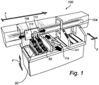
- Figure 1 schematically shows a component mounting or pick and place machine 100 for mounting electronic components on printed circuit boards 121.
- the positioning system of the component mounting machine is of a split-axis type, in which the machine comprises a first axis, indicated by the arrow "x", along which a positioning unit 106 is moved, carrying a work or mounting head 112 and a sensing device 113, and a second axis, indicated by the arrow "y", along which a wagon 116 is moved, providing a working surface or working area, and carrying circuit boards 121 or other suitable substrates onto which components are to be placed.
- the x- and y-axes are essentially orthogonal.
- the machine 100 comprises a positioning system for positioning the work head 112 at a desired location in relation to the circuit boards 121.
- the positioning system comprises linear motors (not shown) for movement of the positioning unit 106 and the wagon or board carrier 116.
- the machine 100 also comprises a control unit (not shown), e.g. a micro processor, for controlling the linear motors.
- the work head 112 is used for picking components from component feeder magazines 50 and placing them onto the circuit boards 121.
- the sensing device 113 is typically, as well as in the illustrated embodiments, in the form of a camera 113, which is connected to an image processing system, and used e.g. for calibrating the positioning system and verifying the position and orientation of the circuit boards.
- a circuit board design determines the layout of the circuits on the circuit board 121, and the desired positions for different components. These positions are entered into the pick and place machine and converted into nominal or machine coordinates. Circuit boards 121, which have been printed according to the determined layout, and which are provided with solder paste, flux, or adhesive at the respective desired positions for the electronic components, are provided on the wagon 116.
- the control system of the machine controls the positioning system such that the work head 112 picks the correct type of component from a component supply or magazine 50 of component feeders, and positions the component at the desired location on the circuit board 121 according to the determined layout.
- the exact held position of the picked component when held by the mount head 112 is determined by a separate camera (not shown), and the machine compensates for any position or orientation offset when picking the component before placing the component on the board.
- a positioning system 102 is shown, wherein the positioning unit 106 is movably suspended from a linear guide arrangement or linear guides 105, extending along an elongated beam 104.
- a linear motor 130 provide movement or motion of the positioning unit.
- the linear motor 130 constitutes a movable member or moving motor member 130a and a stationary member or stationary motor member 130b, wherein an intermediate spacing 131 (cf. Fig. 3 ) separates the movable member 130a from the stationary member 130b.
- an intermediate spacing 131 cf. Fig. 3
- other conventional linear motors may be used, other than the one described herein.
- a cooling arrangement 132 for transportation of heat generated in the movable member 130a is connected to the movable linear motor member 130a by means of a heat conducting interlayer (not shown), e.g. an adhesive.
- the cooling arrangement 132 may also be directly secured to the movable member 130a, with an intermediate layer of heat conducting material, by means of fasteners, such as screws, bolts or the like.
- the cooling arrangement 132 is provided with a number of parallel flanges 134, which are separated for allowing air to flow in between. In a centre portion of the cooling arrangement 132, the flanges 134 are left out creating a flow output 136 for discharge of heated air, i.e. the flanges 134 transfer the heat to the in between flowing air.
- the flow of air is provided by a flow generating arrangement, such as a suction or blow generating arrangement.
- a flow generating arrangement such as a suction or blow generating arrangement.
- the flow generating arrangement is exemplified by a suction generating arrangement.
- the invention is by no means restricted to any particular type of flow generating arrangement.
- the cooling arrangement 132 is basically an elongated hollow flat box provided with flanges 132 at the elongated ends and has one opening 136 for letting out a flow of air (cf. Figs. 4a ).
- the cooling arrangement is preferably made of aluminum.
- the flow output 136 is preferably provided with a suction arrangement.
- a suction device e.g. a fan
- the flow output 136 is preferably provided with a suction arrangement.
- at least one suction device(not shown) e.g. a fan
- the suction arrangement 132 is forced into the longitudinal opposite ends, thereby flowing towards each other against the output 136, and cools the cooling arrangement 132 by flowing in between the flanges, which, in turn, leads the heat to the thereby passing air flow.
- the heated air flow is forced away from the machine 100 by means of the suction arrangement, thereby preventing heat induced deformation of the position unit 106, or portions thereof, and preventing overheating of the movable linear motor member 130a.
- Another example embodiment would be to provide the cooling arrangement with two opposite flow outputs, e.g. arrange a second flow output opposite the first output 136 and, hence, arrange a second suction arrangement at the second output.
- the positioning unit 106 is movably connected to linear guides 105 by means of four engagement elements or guide engaging carriages 138a -d for movable engagement with the guides 105. More specifically, the positioning unit 106 and the moving motor member are secured to the four engaging elements 138a-d by means of four holder elements 140a-c (cf. Figs. 4a and 4b ). These holder elements are designed to compensate for heat induced deformations of the movable member 130a of the linear motor 130. In other words, heat causes the movable member 130a and the thereto connected cooling arrangement 132 to deform, such as prolongation and bending, thereby effecting the relative position of the engagement elements 138a-d. Consequently, the holder elements 140a-d, which will be explained in more detail below, are arranged to take up the heat induced stress in the suspension arrangement, thereby enabling a stress-free operation of the positioning unit 106.
- Fig. 3 is a side view of the positioning system of Fig. 2 , showing the left side of the positioning unit 106 connected to the linear guides 105, which are attached to the elongated beam 104.
- the engagement elements 138a and 138c are movably attached to the linear guides 105, such that the positioning unit which is connected to the elements 138a-d can be moved in a guided manner along the linear guides 105.
- the positioning unit 106 is connected to the engagement elements 138a-d by means of the resilient holder elements 140a-d (138b, 138d, 140b and 140d not shown).
- the cooling arrangement 132 is secured to the engagement elements 138a-d.
- the cooling arrangement 132 holds the moving member 130a of the linear motor.
- the movable member 130a is separated from the stationary member 130b by a spacing, which is sufficient to avoid frictional contact and, at the same time, enable a linear motor effect.
- the flanges 134 defines air flow conduits which leads to the flow output 136 at the centre of the arrangement 132, and, as mentioned above, the flow is forced away by means of a suction arrangement (not shown).
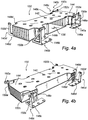
- FIG. 4a and 4b there two plan views of the cooling arrangement 132 having the holder elements 140a-d thereto connected are shown.
- the arrangement 132 is provided with a number of holes 142 in a wall 144 facing the positioning unit 106 (not shown).Thereby, an additional cooling effect may be achieved.
- the holder elements 140a-d comprises a first portion 146a-d adapted to be fixedly secured to the engagement elements 128a-d (not shown), a second portion or moving motor holder 148a-d adapted to secure the moving motor member 130a (not shown) to the guide elements 138a-d (not shown), and a third portion or positioning unit holder 150a-d adapted to secure the positioning unit 106 to the guide elements.
- the moving motor holders 148a-b rigidly connects the cooling arrangement to the guide engaging carriages 138a-b (not shown).
- the configuration of the portions 150a and 150b are different from that of the portions 150c and 150d.
- Upper portions 150a-b have a triangular mechanical structure, such that rigidity in the yz-plane (cf. Fig. 1 ) is achieved, whereas the portions 150c-d have a simpler straight mechanical structure with a rigidity in the y-direction
- all portions 150a-d are resilient in the x-direction, such that, for example, a prolongation of the movable member 130a and the thereto connected cooling arrangement 132 can be compensated for, since the prolongation, in turn, offsets the engagement elements 138a-d further out. Consequently, a force transmission arrangement is provided to transmit the x-directional or linear force from the motor member 130a of the motor 130 to the positional unit 106.
- the holders 140a and 140c are provided with a fourth portion 152a and 152c having the shape of flat pin, extending essentially in the longitudinal direction.
- This fourth portion 152a and 152c constitutes such a force transmission arrangement, which provides a rigid engagement between said positioning unit 106 and motor 130, i.e. the movable motor portion 130a, in the direction parallel with beam extending axis, i.e. along said moving direction for instantaneous transmission of a linear force.
- the force transmission arrangement according to the embodiment in Fig. 4a and 4b . constitutes the two pins 152a and 152c, which forms part of the holder elements 140a and 140c, respectively, other arrangement may be used.
- FIG. 5 is a front view of an example embodiment of a positioning system 202.
- a positioning unit 206 and a driving member 233 containing a movable member of a linear motor (not shown), and optionally a cooling arrangement (cf. Fig. 2 ), are each movably suspended with linear guides 205 which extends along an elongated beam 204.
- the linear motor (not shown) provide a linear movement of the positioning unit.
- a force transmission arrangement 250 operatively connects the positioning unit 206 to the driving member 233, i.e. linear motor, such that a rigid engagement is provided between the positioning unit and the driving member along the moving direction for instantaneous transmission of a linear force
- a positioning system 302 is shown wherein a positioning unit 306 and a driving member 333 (cf. Fig. 5 ) containing a movable member of a linear motor (not shown), preferably with a cooling arrangement attached thereto, are each movably suspended with a linear guide arrangement 305 which extends along an elongated beam 304.
- the linear motor provide a linear movement of the positioning unit.
- the force transmission arrangement constitutes, in the embodiment of Fig. 6 , a pair of elongated pins 352a and 352b which connects the driving member 333, i.e.
- pins 352a and 352b provides a rigid engagement between the positioning unit and the driving member along a direction parallel to the moving direction for instantaneous transmission of a linear force.
- the pins are also resiliently flexible in directions other than the direction parallel to the moving direction, i.e. the engagement is rigid in one direction but otherwise resilient such that forces due to, for example, thermal expansions can be received and absorbed in the pins, thereby leaving the positioning unit 306 unaffected. Consequently, the positioning unit may be accurately positioned.
- the positioning unit 306 is movably attached and suspended to the linear guide arrangement 305 by means of two upper engagement elements 338a-b and a lower element 338c engaging the upper and lower guide of the arrangement 305, respectively.
- an upper guide engaging element 438a suspends the driving member 333 to the upper guide of the linear guide arrangement 305.
- the driving member is movably attached to the arrangement 305 by means of two lower guide engaging 438b and 438c.
- This oppositely and alternatively arranged guide engaging elements 338a-c and 438a-c provides a compact construction, in the sense that the positioning unit 306 and driving member 333 shares a common linear portion of the linear guide arrangement 305.
- This space saving effect, due to the alternatively arranged engagement elements, provides for a more efficient use of the guide arrangement, such that the entire length thereof can be used.
- the engagement elements 338a-c and 438a-c may also be inversely arranged, whereby the movable member 333 is attached to the linear guide arrangement 305 by means of two upper and one lower engagement elements, whereas the positioning unit engages by means of one upper and two lower engagement elements.
- these elements in co-operation with the linear guide arrangement provides a linear motion by means of, for example, ball bearings, roller bearings and/or linear air bearings.
Landscapes
- Engineering & Computer Science (AREA)
- Manufacturing & Machinery (AREA)
- Microelectronics & Electronic Packaging (AREA)
- Mechanical Engineering (AREA)
- Physics & Mathematics (AREA)
- Chemical & Material Sciences (AREA)
- Combustion & Propulsion (AREA)
- Electromagnetism (AREA)
- Power Engineering (AREA)
- Supply And Installment Of Electrical Components (AREA)
- Linear Motors (AREA)
- Machine Tool Units (AREA)
Claims (13)
- Système de positionnement pour le positionnement d'une unité de positionnement (106) le long d'un axe longitudinal, ce système de positionnement comprenant
un dispositif de guidage linéaire (105) pour permettre un mouvement guidé parallèlement audit axe (106) qui est connecté au niveau opératoire audit système de guidage (105),
un moteur comprenant un élément de moteur mobile (130a) connecté au niveau opératoire audit système de guidage linéaire et un élément de moteur stationnaire allongé (130b) s'étendant parallèlement audit axe, l'élément de moteur mobile (130a) étant apte à se déplacer le long de l'élément de moteur stationnaire (130b) pour assurer un mouvement parallèle audit axe ; le système de positionnement étant caractérisé par le fait qu'il comprend en outre :un dispositif de transmission de force (152a-d, 250, 352a-d) connectant au niveau opératoire ledit élément de moteur mobile (130a) à l'unité de positionnement (106), ledit dispositif de transmission de force comportant un accessoire d'engagement combiné rigide et élastique qui est disposé de manière à assurer un engagement entre ladite unité de positionnement et ledit élément de moteur mobile, ledit engagement étant rigide dans un sens rigide parallèle audit axe pour la transmission instantanée d'une force et étant élastique dans des sens autres que ledit sens rigide parallèle audit axe en absorbant ainsi de manière flexible les forces induites thermiquement provenant de l'expansion thermique de l'élément de moteur mobile ;l'unité de positionnement (106) et l'élément de moteur mobile (130a) étant connectés au niveau opératoire au système de guidage linéaire (105) au moyen de deux chariots d'engagement de guide (138a-d), dont au moins un chariot d'engagement de guide est partagé entre l'unité de positionnement
(106) et l'unité de moteur mobile (130a) ; etl'unité de positionnement étant fixée aux chariots d'engagement mobiles (138a-d) au moyen de supports élastiques d'unité de positionnement (140a-d), qui assurent l'engagement précité (110a d). - Système de positionnement selon la revendication 1, dans lequel lesdits supports d'unité de positionnement (140a-d) sont disposés de manière à assurer à l'unité de positionnement une fixation sensiblement rigide par rapport au dit axe dans des sens orthogonaux au dit axe.
- Système de positionnement selon la revendication 1 ou 2, dans lequel le dispositif de guidage comprend au moins deux sections de guidage allongées parallèles audit axe.
- Système de positionnement selon l'une quelconque des revendications précédentes, dans laquelle le système de guidage linéaire comprend au moins une section de guidage allongé supérieure et une inférieure parallèle au dit axe et l'élément de moteur mobile et l'unité de positionnement sont suspendus au moyen d'au moins un chariot d'engagement de guide supérieur et d'un inférieur depuis lesdites sections de guidage supérieure et inférieure respectivement.
- Système de positionnement selon l'une quelconque des revendications précédentes, dans lequel l'unité de positionnement et l'élément de moteur mobile partagent au moins deux chariots d'engagement de guide supérieurs et deux inférieurs, et
dans lequel l'élément de moteur mobile est rattaché fixement auxdits deux chariots d'engagement de guide supérieurs et rattaché aux chariots d'engagement de guide inférieurs au moyen de supports de moteur mobile élastique ou vice-versa et l'unité de positionnement est rattachée au dit deux chariots d'engagement de guide supérieurs et deux chariots d'engagement de guide inférieurs au moyen de supports élastiques d'unité de positionnement. - Système de positionnement selon l'une quelconque des revendications précédentes, dans lequel l'élément de moteur mobile est disposé entre l'élément de moteur stationnaire et l'unité de positionnement, ce qui a pour effet que l'unité de positionnement et l'élément de moteur mobile partagent une section commune d'espace longitudinal du dispositif de guidage linéaire.
- Système de positionnement selon l'une quelconque des revendications précédentes, comprenant en outre un système de refroidissement pour la conduction de chaleur hors de l'élément de moteur mobile, le système de refroidissement étant monté sur l'élément de moteur mobile et l'élément de moteur mobile étant connecté au niveau opératoire au dispositif de guidage linéaire via le dispositif de refroidissement.
- Machine de montage de composants pour le montage de composants électroniques sur les substrats, comprenant un système de positionnement selon l'une quelconque des revendications précédentes.
- Machine de montage de composants selon la revendication 8, comprenant en outre une tête de travail destinée à être positionnée par le système de positionnement.
- Machine de distribution de fluide visqueux sur des substrats, comprenant un système de positionnement selon l'une quelconque des revendications précédentes 1 à 7.
- Machine de distribution selon la revendication 10, ladite machine de distribution étant une machine de projection pour la distribution par projection de gouttes individuelles de fluide visqueux sur des substrats.
- Machine de distribution selon la revendication 10, ladite machine de distribution étant une machine de distribution par projection.
- Machine de distribution selon la revendication 12, comprenant en outre une tête de projection à positionner par le système de positionnement.
Priority Applications (6)
| Application Number | Priority Date | Filing Date | Title |
|---|---|---|---|
| EP08153254.1A EP2105247B1 (fr) | 2008-03-25 | 2008-03-25 | Système de positionnement |
| CN2009801145791A CN102015201B (zh) | 2008-03-25 | 2009-03-25 | 定位系统 |
| US12/934,596 US8384253B2 (en) | 2008-03-25 | 2009-03-25 | Positioning system for positioning a positioning unit along a longitudinal axis |
| JP2011501148A JP5443467B2 (ja) | 2008-03-25 | 2009-03-25 | 位置決めシステム |
| PCT/EP2009/002194 WO2009118178A1 (fr) | 2008-03-25 | 2009-03-25 | Système de positionnement |
| US13/746,967 US8823220B2 (en) | 2008-03-25 | 2013-01-22 | Positioning system for positioning a positioning unit along a longitudinal axis |
Applications Claiming Priority (1)
| Application Number | Priority Date | Filing Date | Title |
|---|---|---|---|
| EP08153254.1A EP2105247B1 (fr) | 2008-03-25 | 2008-03-25 | Système de positionnement |
Publications (2)
| Publication Number | Publication Date |
|---|---|
| EP2105247A1 EP2105247A1 (fr) | 2009-09-30 |
| EP2105247B1 true EP2105247B1 (fr) | 2017-11-29 |
Family
ID=39711821
Family Applications (1)
| Application Number | Title | Priority Date | Filing Date |
|---|---|---|---|
| EP08153254.1A Active EP2105247B1 (fr) | 2008-03-25 | 2008-03-25 | Système de positionnement |
Country Status (5)
| Country | Link |
|---|---|
| US (2) | US8384253B2 (fr) |
| EP (1) | EP2105247B1 (fr) |
| JP (1) | JP5443467B2 (fr) |
| CN (1) | CN102015201B (fr) |
| WO (1) | WO2009118178A1 (fr) |
Families Citing this family (15)
| Publication number | Priority date | Publication date | Assignee | Title |
|---|---|---|---|---|
| EP2105247B1 (fr) * | 2008-03-25 | 2017-11-29 | Mycronic AB | Système de positionnement |
| JP5597050B2 (ja) * | 2010-07-15 | 2014-10-01 | 富士機械製造株式会社 | 基板停止位置制御方法および装置、ならびに基板装着位置制御方法 |
| CN102059576B (zh) * | 2010-11-25 | 2012-02-08 | 西安理工大学 | 双轴直线移动微驱动装置 |
| JP6043993B2 (ja) * | 2011-10-31 | 2016-12-14 | Jukiオートメーションシステムズ株式会社 | 部品実装装置、情報処理装置、情報処理方法及び基板の製造方法 |
| US10111369B2 (en) * | 2012-03-12 | 2018-10-23 | Micronic Mydata AB | Method and device for automatic storage of tape guides |
| JP5598563B1 (ja) * | 2013-03-27 | 2014-10-01 | 株式会社安川電機 | ダイレクトドライブモータ |
| CN103495960A (zh) * | 2013-09-27 | 2014-01-08 | 苏州凯欧机械科技有限公司 | 一种大容腔带冷却管路定位工作台 |
| JP6450923B2 (ja) * | 2013-12-20 | 2019-01-16 | パナソニックIpマネジメント株式会社 | 電子部品実装システムおよび電子部品実装方法ならびに電子部品実装装置 |
| CN103831809B (zh) * | 2014-03-10 | 2016-04-20 | 王远志 | 一种适用于加工工作台便取放五金工具箱 |
| DE102015216026A1 (de) * | 2015-08-21 | 2017-02-23 | Krones Ag | Direktdruckmaschine und Verfahren zur Bedruckung von Behältern mit einem Direktdruck |
| DE102016120464A1 (de) * | 2016-10-26 | 2018-04-26 | Wika Schweiz Ag | Manipulator-System für Montagesysteme |
| WO2019224904A1 (fr) * | 2018-05-22 | 2019-11-28 | 株式会社Fuji | Structure de montage de tête de travail |
| CN113348090A (zh) * | 2019-01-29 | 2021-09-03 | 惠普发展公司,有限责任合伙企业 | 打印机滑架布置结构 |
| CN113814918B (zh) * | 2021-10-22 | 2023-05-26 | 上海东鼎钢结构有限公司 | 一种大门翻板机构安装定位工装及方法 |
| CN114932402A (zh) * | 2022-06-29 | 2022-08-23 | 嵊州祺瑞体育用品股份有限公司 | 滑板滑轮支架螺栓自动紧固装置 |
Family Cites Families (16)
| Publication number | Priority date | Publication date | Assignee | Title |
|---|---|---|---|---|
| US3638933A (en) * | 1970-08-10 | 1972-02-01 | Yosemite Lab | Precision x-y positioning table |
| JPH081982B2 (ja) * | 1985-04-17 | 1996-01-10 | 株式会社日立製作所 | 電子部品搭載方法及び装置 |
| DE3618194A1 (de) * | 1986-05-30 | 1987-12-03 | Bosch Gmbh Robert | Lineareinheit |
| DE4032820C1 (fr) * | 1990-10-16 | 1991-11-07 | Deutsche Star Gmbh, 8720 Schweinfurt, De | |
| DE19839334A1 (de) * | 1998-08-28 | 2000-03-02 | Wurst Karl Heinz | Antriebseinheit für eine Maschine, vorzugsweise eine Bearbeitungsmaschine |
| US6754551B1 (en) * | 2000-06-29 | 2004-06-22 | Printar Ltd. | Jet print apparatus and method for printed circuit board manufacturing |
| US20020041481A1 (en) * | 2000-09-28 | 2002-04-11 | Yoshinori Kano | Linear motor and electronic component feeding apparatus |
| JP4542305B2 (ja) * | 2001-09-28 | 2010-09-15 | Thk株式会社 | 駆動案内装置 |
| DE10309879B4 (de) * | 2003-03-06 | 2006-08-31 | Siemens Ag | Vorrichtung zum Bestücken von Substraten mit elektrischen Bauelementen |
| JP4039342B2 (ja) * | 2003-08-20 | 2008-01-30 | 松下電器産業株式会社 | 電子部品実装用装置の直動機構 |
| JPWO2005122368A1 (ja) * | 2004-06-11 | 2008-04-10 | 株式会社安川電機 | ムービングマグネット形リニアスライダ |
| DE102004036992A1 (de) | 2004-07-30 | 2006-03-23 | Siemens Ag | Vorrichtung zum Anbinden eines Linearmotorläufers an eine Linearführung |
| JP4672315B2 (ja) * | 2004-09-06 | 2011-04-20 | 東芝機械株式会社 | リニアモータおよびリニア移動ステージ装置 |
| JP2007270860A (ja) * | 2006-03-30 | 2007-10-18 | Smc Corp | 電動アクチュエータ |
| JP2008067463A (ja) | 2006-09-06 | 2008-03-21 | Nsk Ltd | リニアモータ式テーブル装置 |
| EP2105247B1 (fr) * | 2008-03-25 | 2017-11-29 | Mycronic AB | Système de positionnement |
-
2008
- 2008-03-25 EP EP08153254.1A patent/EP2105247B1/fr active Active
-
2009
- 2009-03-25 CN CN2009801145791A patent/CN102015201B/zh active Active
- 2009-03-25 US US12/934,596 patent/US8384253B2/en active Active
- 2009-03-25 JP JP2011501148A patent/JP5443467B2/ja not_active Expired - Fee Related
- 2009-03-25 WO PCT/EP2009/002194 patent/WO2009118178A1/fr active Application Filing
-
2013
- 2013-01-22 US US13/746,967 patent/US8823220B2/en active Active
Non-Patent Citations (1)
| Title |
|---|
| None * |
Also Published As
| Publication number | Publication date |
|---|---|
| CN102015201A (zh) | 2011-04-13 |
| US8823220B2 (en) | 2014-09-02 |
| WO2009118178A1 (fr) | 2009-10-01 |
| EP2105247A1 (fr) | 2009-09-30 |
| JP5443467B2 (ja) | 2014-03-19 |
| JP2011519473A (ja) | 2011-07-07 |
| US20120139366A1 (en) | 2012-06-07 |
| US20130133187A1 (en) | 2013-05-30 |
| CN102015201B (zh) | 2013-03-27 |
| US8384253B2 (en) | 2013-02-26 |
Similar Documents
| Publication | Publication Date | Title |
|---|---|---|
| EP2105247B1 (fr) | Système de positionnement | |
| US7017261B2 (en) | Component suction device, component mounting apparatus and component mounting method | |
| US20140291270A1 (en) | Positioning Device | |
| KR101282165B1 (ko) | 실장기 | |
| US7259483B2 (en) | Linear driving mechanism of electronic components mounting apparatus | |
| JP7223695B2 (ja) | 部品装着機 | |
| JP5901743B2 (ja) | リニアモータ装置 | |
| EP2804458B1 (fr) | Dispositif de montage de composants | |
| JP4360869B2 (ja) | 部品実装機 | |
| JP6816282B2 (ja) | 部品装着機 | |
| JP4096837B2 (ja) | 電子部品実装用装置の直動機構 | |
| JP2005252073A (ja) | 電子部品実装装置 | |
| JP2007073691A (ja) | 表面実装機 | |
| CN221019149U (zh) | 焊接设备 | |
| JP4516663B2 (ja) | 直動装置、xy移動装置及び電子部品装着装置 | |
| JP3992359B2 (ja) | 装着ヘッド | |
| US20190111525A1 (en) | Actuator, mount head unit, mounting apparatus, and driving method of actuator | |
| JP2005311104A (ja) | 電子部品実装装置 | |
| EP3826446A1 (fr) | Dispositif d'alimentation en composants | |
| JP2005064417A (ja) | 電子部品実装用装置の直動機構 | |
| JP4080315B2 (ja) | 作業ヘッドの移動方法 | |
| JP2011124404A (ja) | 直動装置及び部品実装機 |
Legal Events
| Date | Code | Title | Description |
|---|---|---|---|
| PUAI | Public reference made under article 153(3) epc to a published international application that has entered the european phase |
Free format text: ORIGINAL CODE: 0009012 |
|
| AK | Designated contracting states |
Kind code of ref document: A1 Designated state(s): AT BE BG CH CY CZ DE DK EE ES FI FR GB GR HR HU IE IS IT LI LT LU LV MC MT NL NO PL PT RO SE SI SK TR |
|
| AX | Request for extension of the european patent |
Extension state: AL BA MK RS |
|
| 17P | Request for examination filed |
Effective date: 20100311 |
|
| AKX | Designation fees paid |
Designated state(s): DE FR |
|
| 17Q | First examination report despatched |
Effective date: 20120911 |
|
| GRAP | Despatch of communication of intention to grant a patent |
Free format text: ORIGINAL CODE: EPIDOSNIGR1 |
|
| STAA | Information on the status of an ep patent application or granted ep patent |
Free format text: STATUS: GRANT OF PATENT IS INTENDED |
|
| INTG | Intention to grant announced |
Effective date: 20170530 |
|
| GRAS | Grant fee paid |
Free format text: ORIGINAL CODE: EPIDOSNIGR3 |
|
| GRAA | (expected) grant |
Free format text: ORIGINAL CODE: 0009210 |
|
| STAA | Information on the status of an ep patent application or granted ep patent |
Free format text: STATUS: THE PATENT HAS BEEN GRANTED |
|
| RAP1 | Party data changed (applicant data changed or rights of an application transferred) |
Owner name: MYCRONIC AB |
|
| AK | Designated contracting states |
Kind code of ref document: B1 Designated state(s): DE FR |
|
| REG | Reference to a national code |
Ref country code: DE Ref legal event code: R096 Ref document number: 602008053143 Country of ref document: DE |
|
| REG | Reference to a national code |
Ref country code: FR Ref legal event code: PLFP Year of fee payment: 11 |
|
| REG | Reference to a national code |
Ref country code: DE Ref legal event code: R097 Ref document number: 602008053143 Country of ref document: DE |
|
| PLBE | No opposition filed within time limit |
Free format text: ORIGINAL CODE: 0009261 |
|
| STAA | Information on the status of an ep patent application or granted ep patent |
Free format text: STATUS: NO OPPOSITION FILED WITHIN TIME LIMIT |
|
| 26N | No opposition filed |
Effective date: 20180830 |
|
| PGFP | Annual fee paid to national office [announced via postgrant information from national office to epo] |
Ref country code: FR Payment date: 20220218 Year of fee payment: 15 |
|
| P01 | Opt-out of the competence of the unified patent court (upc) registered |
Effective date: 20230526 |
|
| PG25 | Lapsed in a contracting state [announced via postgrant information from national office to epo] |
Ref country code: FR Free format text: LAPSE BECAUSE OF NON-PAYMENT OF DUE FEES Effective date: 20230331 |
|
| PGFP | Annual fee paid to national office [announced via postgrant information from national office to epo] |
Ref country code: DE Payment date: 20240220 Year of fee payment: 17 |